EP4007149A1 - Convertisseur - Google Patents
Convertisseur Download PDFInfo
- Publication number
- EP4007149A1 EP4007149A1 EP22152934.0A EP22152934A EP4007149A1 EP 4007149 A1 EP4007149 A1 EP 4007149A1 EP 22152934 A EP22152934 A EP 22152934A EP 4007149 A1 EP4007149 A1 EP 4007149A1
- Authority
- EP
- European Patent Office
- Prior art keywords
- box
- heat radiator
- disposed
- magnetic element
- electronic device
- Prior art date
- Legal status (The legal status is an assumption and is not a legal conclusion. Google has not performed a legal analysis and makes no representation as to the accuracy of the status listed.)
- Granted
Links
Images
Classifications
-
- H—ELECTRICITY
- H05—ELECTRIC TECHNIQUES NOT OTHERWISE PROVIDED FOR
- H05K—PRINTED CIRCUITS; CASINGS OR CONSTRUCTIONAL DETAILS OF ELECTRIC APPARATUS; MANUFACTURE OF ASSEMBLAGES OF ELECTRICAL COMPONENTS
- H05K7/00—Constructional details common to different types of electric apparatus
- H05K7/20—Modifications to facilitate cooling, ventilating, or heating
- H05K7/2089—Modifications to facilitate cooling, ventilating, or heating for power electronics, e.g. for inverters for controlling motor
- H05K7/20909—Forced ventilation, e.g. on heat dissipaters coupled to components
-
- H—ELECTRICITY
- H02—GENERATION; CONVERSION OR DISTRIBUTION OF ELECTRIC POWER
- H02M—APPARATUS FOR CONVERSION BETWEEN AC AND AC, BETWEEN AC AND DC, OR BETWEEN DC AND DC, AND FOR USE WITH MAINS OR SIMILAR POWER SUPPLY SYSTEMS; CONVERSION OF DC OR AC INPUT POWER INTO SURGE OUTPUT POWER; CONTROL OR REGULATION THEREOF
- H02M7/00—Conversion of AC power input into DC power output; Conversion of DC power input into AC power output
- H02M7/003—Constructional details, e.g. physical layout, assembly, wiring or busbar connections
Definitions
- the disclosure relates to the technical field of power electronic technology, and in particular to an inverter.
- An inverter in the conventional technology mainly includes an electronic device, a magnetic element, a heat radiator and a box. There are two common arrangements for the inverter as follows.
- the electronic device and the magnetic element are disposed in a box, and the heat radiator is disposed outside the box.
- the heat radiator is disposed outside the box.
- the electronic device is disposed inside a box, the magnetic element and the heat radiator are disposed in parallel.
- a fan is provided to blow the magnetic element and the heat radiator for heat radiation, the cold air blast firstly flows through the heat radiator and then passes the magnetic element.
- the magnetic element may block the cold air blast flowed through the heat radiator, therefore the radiation effect of the heat radiator is reduced.
- an inverter is provided according to the disclosure, to solve the problem of poor radiation effect in the conventional technology.
- An inverter which includes: an electronic device, a magnetic element, a heat radiator, a cooling fan, a first box and a second box connected with each other via a mounting plate, where
- the first box and the second box may share one mounting plate, and may be located on two parallel mounting surfaces of the mounting plate respectively.
- the heat radiator may be disposed on the mounting plate inside the second box; and the electronic device may be disposed on the mounting plate inside the first box.
- the magnetic element may be disposed on a top plate of the second box.
- the cooling fan may be disposed on a side plate of the second box inside the second box, the side plate may be perpendicular to gaps between fins of the heat radiator.
- one or more vents may be disposed in another side plate of the second box, the another side plate may be perpendicular to the gaps between the fins of the heat radiator.
- the number of the vents may be more than one, and the vents may be uniformly disposed at positions corresponding to the gaps between the fins of the heat radiator.
- the number of the cooling fans may be four.
- the electronic device is disposed inside the first box; the heat radiator and the cooling fan are disposed inside the second box; and the magnetic element is disposed outside the first box and the second box.
- the cooling effect on the electronic device inside the first box and the heat radiator inside the second box may be less affected by the heat generated by the magnetic element.
- the magnetic element being disposed outside the first box and the second box is also beneficial to heat radiation of the magnetic element.
- the cooling fan only blows the heat radiator for heat radiation, there is not a case that the magnetic element blocks the cold air blast flowed through the heat radiator as in the conventional technology, therefore a more unobstructed air duct is formed, and the radiation effect is improved.
- An inverter is provided according to the disclosure, to solve the problem of the poor radiation effect in the conventional technology.
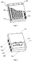
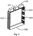
- the inverter includes: an electronic device 101, a magnetic element 102, a heat radiator 103, a cooling fan 104, a first box 201 and a second box 202 connected with each other via a mounting plate 211, where
- the magnetic element 102 being disposed outside the first box 201 and the second box 202 may lead to a result that the cooling effect on the electronic device 101 inside the first box 201 and the heat radiator 103 inside the second box 202 is less affected by the heat generated by the magnetic element 102.
- the magnetic element 102 is disposed outside the first box 201 and the second box 202, and is directly contacted with outside air, the heat generated by the magnetic element 102 is easy to be exchanged with the air, hence the temperature of the magnetic element 102 is reduced, and it is beneficial to heat radiation of the magnetic element 102, the operation efficiency of the magnetic element 102 is improved.
- the cooling fan 104 only blows the heat radiator 103 for heat radiation, there is not a case that the magnetic element blocks the cold air blast flowed through the heat radiator as in the conventional technology, therefore a more unobstructed air duct is formed, and the radiation effect is improved.
- the magnetic element 102 being disposed outside the first box 201 and the second box 202 may lead to a result that the heat radiation of the electronic device 101 inside the first box 201 and the heat radiator 103 inside the second box 202 is less affected by the heat generated by the magnetic element.
- each of the first box 201 and the second box 202 may include the mounting plate 211 to mount a respective device.
- the first box 201 and the second box 202 share one mounting plate 211, and are located on two parallel mounting surfaces of the mounting plate 211 respectively.
- the electronic device 101 and the heat radiator 103 are mounted on two parallel mounting surfaces of the mounting plate 211 respectively, and the two parallel mounting surfaces of the mounting plate 211 may be two surfaces having the largest areas.
- the two parallel mounting surfaces of the mounting plate 211 may be two surfaces, for mounting the devices, not having the largest areas, which is not limited herein and defined depending on specific application.
- the first box 201 and the second box 202 are respectively disposed on the two parallel mounting surfaces of the mounting plate 211 so that the first box 201 and the second box 202 are connected in a back-to-back way.
- both the first box 201 and the second box 202 have five surfaces, and are mounted on a front surface and a back surface of the mounting plate 211.
- the heat radiator 103 is disposed on the mounting plate 211 inside the second box 202 (as shown in Figure 1 ); and the electronic device 101 is disposed on the mounting plate 211 inside the first box 201 (as shown in Figure 2 ).
- the heat radiator 103 and the electronic device 101 are disposed at two sides of the mounting plate 211 respectively so that the heat radiator 103 and the electronic device 101 are contacted in a back-to-back way via the mounting plated 211. In this way, the heat radiator 103 can operate well for the heat radiation for the electronic device 101.
- the magnetic element 102 is disposed on a top plate 221 of the second box 202.
- a position where the magnetic element 102 is disposed is named as the top plate 221 of the second box 202, and a direction in the description is referred to a placement direction of the inverter when the inverter operates.
- the magnetic element 102 is disposed on the top plate 221 of the box and is directly contacted with outside air, the heat generated by the magnetic element 102 is easy to be exchanged with the air, hence the temperature of the magnetic element 102 is reduced, and it is beneficial to heat radiation of the magnetic element 102, the operation efficiency of the magnetic element 102 is improved.
- the cooling fan 104 is disposed on a side plate 222 of the second box 202 inside the second box 202, the side plate 222 is perpendicular to gaps between fins of the heat radiator 103.
- a position of the second box 202 where the cooling fan 104 is disposed is the side plate 222 of the second box 202 perpendicular to the gaps between the fins of the heat radiator 103. In this way, it is ensured that the cold air blast generated by the cooling fan 104 can flow through the heat radiator 103 in a large area, and it is beneficial to the heat radiation of the heat radiator 103.
- one or more vents are disposed in another side plate 223 of the second box 202, the another side plate 223 is perpendicular to the gaps between the fins of the heat radiator 103.
- the number of the vents is more than one, and the vents are uniformly disposed at positions corresponding to the gaps between the fins of the heat radiator 103.
- the positions corresponding to the gaps between the fins of the heat radiator 103 correspond to projection of the gaps between the fins of the heat radiator 103 on the side plate 223.
- the cooling fan 104 and the vents are disposed at two sides of the heat radiator 103 respectively, so that the cold air blast generated by the cooling fan 104 can pass the gaps between the fins of the heat radiator 103 and the vents, thus an unobstructed air duct can be formed, and it is beneficial to the heat radiation of the heat radiator 103.
- vents may depend on the specific application, which is not limited herein.
- the number of the cooling fans 104 is four.
- the number of the cooling fans 104 is not limited.
- the cooling fans 104 shown in the drawings show only an example, and the number of the cooling fans 104 may depend on the specific application.
Landscapes
- Engineering & Computer Science (AREA)
- Microelectronics & Electronic Packaging (AREA)
- Physics & Mathematics (AREA)
- Thermal Sciences (AREA)
- Power Engineering (AREA)
- Cooling Or The Like Of Electrical Apparatus (AREA)
- Inverter Devices (AREA)
Applications Claiming Priority (2)
| Application Number | Priority Date | Filing Date | Title |
|---|---|---|---|
| CN201520412624.4U CN204669236U (zh) | 2015-06-15 | 2015-06-15 | 一种逆变器 |
| EP16157092.4A EP3160029B1 (fr) | 2015-06-15 | 2016-02-24 | Onduleur |
Related Parent Applications (2)
| Application Number | Title | Priority Date | Filing Date |
|---|---|---|---|
| EP16157092.4A Division EP3160029B1 (fr) | 2015-06-15 | 2016-02-24 | Onduleur |
| EP16157092.4A Division-Into EP3160029B1 (fr) | 2015-06-15 | 2016-02-24 | Onduleur |
Publications (3)
| Publication Number | Publication Date |
|---|---|
| EP4007149A1 true EP4007149A1 (fr) | 2022-06-01 |
| EP4007149B1 EP4007149B1 (fr) | 2024-05-22 |
| EP4007149C0 EP4007149C0 (fr) | 2024-05-22 |
Family
ID=54139576
Family Applications (2)
| Application Number | Title | Priority Date | Filing Date |
|---|---|---|---|
| EP22152934.0A Active EP4007149B1 (fr) | 2015-06-15 | 2016-02-24 | Convertisseur |
| EP16157092.4A Active EP3160029B1 (fr) | 2015-06-15 | 2016-02-24 | Onduleur |
Family Applications After (1)
| Application Number | Title | Priority Date | Filing Date |
|---|---|---|---|
| EP16157092.4A Active EP3160029B1 (fr) | 2015-06-15 | 2016-02-24 | Onduleur |
Country Status (5)
| Country | Link |
|---|---|
| US (1) | US9795066B2 (fr) |
| EP (2) | EP4007149B1 (fr) |
| JP (1) | JP6632061B2 (fr) |
| CN (1) | CN204669236U (fr) |
| ES (1) | ES2912333T3 (fr) |
Families Citing this family (10)
| Publication number | Priority date | Publication date | Assignee | Title |
|---|---|---|---|---|
| CN107155279B (zh) * | 2016-03-03 | 2020-06-02 | 台达电子工业股份有限公司 | 层架式调温装置及调温系统 |
| CN108258919A (zh) * | 2018-02-09 | 2018-07-06 | 德清众益光电有限公司 | 防尘透气除静电的逆变器外壳 |
| USD920242S1 (en) * | 2018-04-13 | 2021-05-25 | Abb Power Grids Switzerland Ag | Transformer monitor |
| USD887355S1 (en) * | 2018-04-20 | 2020-06-16 | Delta Electronics, Inc. | Inverter |
| USD914594S1 (en) * | 2018-06-08 | 2021-03-30 | Siemens Ltd., China | Automation demo case |
| USD894833S1 (en) * | 2018-11-05 | 2020-09-01 | Fuji Electric Co., Ltd. | Inverter |
| USD889405S1 (en) * | 2018-11-15 | 2020-07-07 | Hevo, Inc. | Inverter component of a charging system |
| USD896753S1 (en) * | 2018-12-31 | 2020-09-22 | Panoramic Power Ltd. | Modularly connecting bridge, meter and power supply unit assembly |
| JP1735838S (ja) * | 2022-01-14 | 2023-01-31 | 電流インバータ | |
| IT202200026742A1 (it) * | 2022-12-23 | 2024-06-23 | Friem S P A | Apparato convertitore elettronico di potenza comprendente moduli convertitori tra loro sovrapposti ed una unità di raffreddamento a ventilazione forzata |
Citations (6)
| Publication number | Priority date | Publication date | Assignee | Title |
|---|---|---|---|---|
| US4772999A (en) * | 1986-12-16 | 1988-09-20 | Merlin Gerin | Static converter, especially for an uninterruptible electrical power supply system |
| GB2385469A (en) * | 2002-02-19 | 2003-08-20 | Sansha Electric Mfg Co Ltd | Power supply apparatus |
| WO2009136815A1 (fr) * | 2008-05-06 | 2009-11-12 | Общество С Ограниченной Ответственностью "Haучнo- Производственное Предприятие "Фeб" | Poste de soudage à inversion |
| US20120002452A1 (en) * | 2010-06-30 | 2012-01-05 | Guil Hetzroni | Compact inverter |
| CN202816620U (zh) * | 2012-09-18 | 2013-03-20 | 天津市信诺创能科技发展有限公司 | 一种大功率高频变压器 |
| US20140321065A1 (en) * | 2011-11-21 | 2014-10-30 | Autonetworks Technologies, Ltd. | Dc-dc converter |
Family Cites Families (19)
| Publication number | Priority date | Publication date | Assignee | Title |
|---|---|---|---|---|
| KR920005988B1 (ko) * | 1988-08-31 | 1992-07-25 | 가부시기가이샤 히다찌세이사꾸쇼 | 인버터장치 |
| JP2809026B2 (ja) * | 1992-09-30 | 1998-10-08 | 三菱電機株式会社 | インバ−タ装置およびインバ−タ装置の使用方法 |
| JP3575328B2 (ja) * | 1999-04-23 | 2004-10-13 | 松下電工株式会社 | 太陽光発電装置 |
| EP1283589A3 (fr) * | 2001-08-09 | 2003-03-26 | Bombardier Transportation GmbH | Module convertisseur de puissance |
| GB2411050A (en) * | 2004-02-16 | 2005-08-17 | E2V Tech Uk Ltd | Electrical apparatus cooling system |
| JP5013160B2 (ja) * | 2005-12-28 | 2012-08-29 | 株式会社安川電機 | インバータ装置 |
| ATE545325T1 (de) * | 2007-11-28 | 2012-02-15 | Voltwerk Electronics Gmbh | Umrichter |
| US8004844B2 (en) * | 2008-03-12 | 2011-08-23 | Kmw, Inc. | Enclosure device of wireless communication apparatus |
| US9192079B2 (en) * | 2008-09-26 | 2015-11-17 | Rockwell Automation Technologies, Inc. | Power electronic module cooling system and method |
| JP2010130779A (ja) * | 2008-11-27 | 2010-06-10 | Yaskawa Electric Corp | モータ制御装置 |
| JP2011192809A (ja) * | 2010-03-15 | 2011-09-29 | Omron Corp | パワーコンディショナー装置およびこの装置に使用するモジュール基板構造 |
| TW201143585A (en) * | 2010-05-17 | 2011-12-01 | Hon Hai Prec Ind Co Ltd | Electronic device |
| JP5348623B2 (ja) * | 2010-09-10 | 2013-11-20 | 株式会社安川電機 | 電子機器装置 |
| KR101189451B1 (ko) * | 2010-12-24 | 2012-10-09 | 엘지전자 주식회사 | 인버터 스택 |
| CN102355149A (zh) * | 2011-10-18 | 2012-02-15 | 华为技术有限公司 | 逆变器、密封风道和散热系统 |
| JP5990778B2 (ja) * | 2012-10-31 | 2016-09-14 | パナソニックIpマネジメント株式会社 | 電気機器 |
| DE102013100607A1 (de) * | 2013-01-22 | 2014-07-24 | Sma Solar Technology Ag | Wechselrichter mit zweiteiligem Gehäuse |
| US11027354B2 (en) * | 2013-06-24 | 2021-06-08 | Illinois Tool Works Inc. | Modular power conversion system and method |
| KR20150025755A (ko) * | 2013-08-30 | 2015-03-11 | 엘에스산전 주식회사 | 인버터 냉각장치 |
-
2015
- 2015-06-15 CN CN201520412624.4U patent/CN204669236U/zh not_active Expired - Lifetime
-
2016
- 2016-02-23 US US15/050,574 patent/US9795066B2/en active Active
- 2016-02-24 EP EP22152934.0A patent/EP4007149B1/fr active Active
- 2016-02-24 EP EP16157092.4A patent/EP3160029B1/fr active Active
- 2016-02-24 ES ES16157092T patent/ES2912333T3/es active Active
- 2016-02-26 JP JP2016035070A patent/JP6632061B2/ja active Active
Patent Citations (6)
| Publication number | Priority date | Publication date | Assignee | Title |
|---|---|---|---|---|
| US4772999A (en) * | 1986-12-16 | 1988-09-20 | Merlin Gerin | Static converter, especially for an uninterruptible electrical power supply system |
| GB2385469A (en) * | 2002-02-19 | 2003-08-20 | Sansha Electric Mfg Co Ltd | Power supply apparatus |
| WO2009136815A1 (fr) * | 2008-05-06 | 2009-11-12 | Общество С Ограниченной Ответственностью "Haучнo- Производственное Предприятие "Фeб" | Poste de soudage à inversion |
| US20120002452A1 (en) * | 2010-06-30 | 2012-01-05 | Guil Hetzroni | Compact inverter |
| US20140321065A1 (en) * | 2011-11-21 | 2014-10-30 | Autonetworks Technologies, Ltd. | Dc-dc converter |
| CN202816620U (zh) * | 2012-09-18 | 2013-03-20 | 天津市信诺创能科技发展有限公司 | 一种大功率高频变压器 |
Also Published As
| Publication number | Publication date |
|---|---|
| CN204669236U (zh) | 2015-09-23 |
| JP6632061B2 (ja) | 2020-01-15 |
| EP3160029A1 (fr) | 2017-04-26 |
| US20160366794A1 (en) | 2016-12-15 |
| JP2017005975A (ja) | 2017-01-05 |
| US9795066B2 (en) | 2017-10-17 |
| EP4007149B1 (fr) | 2024-05-22 |
| EP3160029B1 (fr) | 2022-03-09 |
| ES2912333T3 (es) | 2022-05-25 |
| EP4007149C0 (fr) | 2024-05-22 |
Similar Documents
| Publication | Publication Date | Title |
|---|---|---|
| EP4007149A1 (fr) | Convertisseur | |
| TWI405945B (zh) | 氣冷式熱交換器及其適用之電子設備 | |
| WO2019114311A1 (fr) | Climatiseur et coffret électrique associé | |
| CN204425850U (zh) | 一种伺服驱动器的外壳结构 | |
| WO2019228420A1 (fr) | Dispositif de traitement de données | |
| JP2015065747A (ja) | 配電盤装置 | |
| US20210063090A1 (en) | Inverter And Heat Dissipation Device Thereof | |
| CN102368135A (zh) | 防烟尘装置及投影机 | |
| CN108089680A (zh) | 一种散热方法及装置 | |
| CN207164447U (zh) | 一种具有高效散热能力的投影机装置 | |
| CN204203876U (zh) | 具有散热功效的电路板 | |
| CN219831754U (zh) | 一种工业用计算机壳体结构 | |
| CN205912410U (zh) | 一种电子通讯设备的气冷系统 | |
| WO2023186147A1 (fr) | Appareil de dissipation de chaleur et dispositif informatique | |
| CN204964978U (zh) | 一种高效散热投影仪 | |
| CN211017946U (zh) | 一种继电保护装置辅助降温结构 | |
| CN103019319A (zh) | 服务器 | |
| TWM638809U (zh) | 散熱裝置及服務器 | |
| CN206490948U (zh) | 穿墙式散热组件 | |
| CN108120040A (zh) | 温控设备及其热交换单元 | |
| CN216596151U (zh) | 一种数据处理装置内的四显卡散热集成模组 | |
| CN205227430U (zh) | 电磁炉的散热结构 | |
| CN220674203U (zh) | 电子装置及其热管直触式散热模组 | |
| CN107072110B (zh) | 一种用于伺服驱动器的穿墙式散热组件 | |
| CN212259698U (zh) | 一种具有防磁效果的路由器屏蔽罩 |
Legal Events
| Date | Code | Title | Description |
|---|---|---|---|
| PUAI | Public reference made under article 153(3) epc to a published international application that has entered the european phase |
Free format text: ORIGINAL CODE: 0009012 |
|
| STAA | Information on the status of an ep patent application or granted ep patent |
Free format text: STATUS: REQUEST FOR EXAMINATION WAS MADE |
|
| 17P | Request for examination filed |
Effective date: 20220124 |
|
| AC | Divisional application: reference to earlier application |
Ref document number: 3160029 Country of ref document: EP Kind code of ref document: P |
|
| AK | Designated contracting states |
Kind code of ref document: A1 Designated state(s): AL AT BE BG CH CY CZ DE DK EE ES FI FR GB GR HR HU IE IS IT LI LT LU LV MC MK MT NL NO PL PT RO RS SE SI SK SM TR |
|
| STAA | Information on the status of an ep patent application or granted ep patent |
Free format text: STATUS: EXAMINATION IS IN PROGRESS |
|
| 17Q | First examination report despatched |
Effective date: 20230105 |
|
| GRAP | Despatch of communication of intention to grant a patent |
Free format text: ORIGINAL CODE: EPIDOSNIGR1 |
|
| STAA | Information on the status of an ep patent application or granted ep patent |
Free format text: STATUS: GRANT OF PATENT IS INTENDED |
|
| INTG | Intention to grant announced |
Effective date: 20240219 |
|
| GRAS | Grant fee paid |
Free format text: ORIGINAL CODE: EPIDOSNIGR3 |
|
| GRAA | (expected) grant |
Free format text: ORIGINAL CODE: 0009210 |
|
| STAA | Information on the status of an ep patent application or granted ep patent |
Free format text: STATUS: THE PATENT HAS BEEN GRANTED |
|
| AC | Divisional application: reference to earlier application |
Ref document number: 3160029 Country of ref document: EP Kind code of ref document: P |
|
| AK | Designated contracting states |
Kind code of ref document: B1 Designated state(s): AL AT BE BG CH CY CZ DE DK EE ES FI FR GB GR HR HU IE IS IT LI LT LU LV MC MK MT NL NO PL PT RO RS SE SI SK SM TR |
|
| REG | Reference to a national code |
Ref country code: GB Ref legal event code: FG4D |
|
| REG | Reference to a national code |
Ref country code: CH Ref legal event code: EP |
|
| REG | Reference to a national code |
Ref country code: DE Ref legal event code: R096 Ref document number: 602016087700 Country of ref document: DE |
|
| REG | Reference to a national code |
Ref country code: IE Ref legal event code: FG4D |
|
| U01 | Request for unitary effect filed |
Effective date: 20240604 |
|
| U07 | Unitary effect registered |
Designated state(s): AT BE BG DE DK EE FI FR IT LT LU LV MT NL PT SE SI Effective date: 20240612 |
|
| PG25 | Lapsed in a contracting state [announced via postgrant information from national office to epo] |
Ref country code: IS Free format text: LAPSE BECAUSE OF FAILURE TO SUBMIT A TRANSLATION OF THE DESCRIPTION OR TO PAY THE FEE WITHIN THE PRESCRIBED TIME-LIMIT Effective date: 20240922 |
|
| PG25 | Lapsed in a contracting state [announced via postgrant information from national office to epo] |
Ref country code: HR Free format text: LAPSE BECAUSE OF FAILURE TO SUBMIT A TRANSLATION OF THE DESCRIPTION OR TO PAY THE FEE WITHIN THE PRESCRIBED TIME-LIMIT Effective date: 20240522 |
|
| PG25 | Lapsed in a contracting state [announced via postgrant information from national office to epo] |
Ref country code: GR Free format text: LAPSE BECAUSE OF FAILURE TO SUBMIT A TRANSLATION OF THE DESCRIPTION OR TO PAY THE FEE WITHIN THE PRESCRIBED TIME-LIMIT Effective date: 20240823 |
|
| PG25 | Lapsed in a contracting state [announced via postgrant information from national office to epo] |
Ref country code: ES Free format text: LAPSE BECAUSE OF FAILURE TO SUBMIT A TRANSLATION OF THE DESCRIPTION OR TO PAY THE FEE WITHIN THE PRESCRIBED TIME-LIMIT Effective date: 20240522 |
|
| PG25 | Lapsed in a contracting state [announced via postgrant information from national office to epo] |
Ref country code: PL Free format text: LAPSE BECAUSE OF FAILURE TO SUBMIT A TRANSLATION OF THE DESCRIPTION OR TO PAY THE FEE WITHIN THE PRESCRIBED TIME-LIMIT Effective date: 20240522 |
|
| PG25 | Lapsed in a contracting state [announced via postgrant information from national office to epo] |
Ref country code: PL Free format text: LAPSE BECAUSE OF FAILURE TO SUBMIT A TRANSLATION OF THE DESCRIPTION OR TO PAY THE FEE WITHIN THE PRESCRIBED TIME-LIMIT Effective date: 20240522 Ref country code: NO Free format text: LAPSE BECAUSE OF FAILURE TO SUBMIT A TRANSLATION OF THE DESCRIPTION OR TO PAY THE FEE WITHIN THE PRESCRIBED TIME-LIMIT Effective date: 20240822 Ref country code: IS Free format text: LAPSE BECAUSE OF FAILURE TO SUBMIT A TRANSLATION OF THE DESCRIPTION OR TO PAY THE FEE WITHIN THE PRESCRIBED TIME-LIMIT Effective date: 20240922 Ref country code: HR Free format text: LAPSE BECAUSE OF FAILURE TO SUBMIT A TRANSLATION OF THE DESCRIPTION OR TO PAY THE FEE WITHIN THE PRESCRIBED TIME-LIMIT Effective date: 20240522 Ref country code: GR Free format text: LAPSE BECAUSE OF FAILURE TO SUBMIT A TRANSLATION OF THE DESCRIPTION OR TO PAY THE FEE WITHIN THE PRESCRIBED TIME-LIMIT Effective date: 20240823 Ref country code: ES Free format text: LAPSE BECAUSE OF FAILURE TO SUBMIT A TRANSLATION OF THE DESCRIPTION OR TO PAY THE FEE WITHIN THE PRESCRIBED TIME-LIMIT Effective date: 20240522 Ref country code: RS Free format text: LAPSE BECAUSE OF FAILURE TO SUBMIT A TRANSLATION OF THE DESCRIPTION OR TO PAY THE FEE WITHIN THE PRESCRIBED TIME-LIMIT Effective date: 20240822 |
|
| PG25 | Lapsed in a contracting state [announced via postgrant information from national office to epo] |
Ref country code: CZ Free format text: LAPSE BECAUSE OF FAILURE TO SUBMIT A TRANSLATION OF THE DESCRIPTION OR TO PAY THE FEE WITHIN THE PRESCRIBED TIME-LIMIT Effective date: 20240522 |
|
| PG25 | Lapsed in a contracting state [announced via postgrant information from national office to epo] |
Ref country code: RO Free format text: LAPSE BECAUSE OF FAILURE TO SUBMIT A TRANSLATION OF THE DESCRIPTION OR TO PAY THE FEE WITHIN THE PRESCRIBED TIME-LIMIT Effective date: 20240522 Ref country code: SK Free format text: LAPSE BECAUSE OF FAILURE TO SUBMIT A TRANSLATION OF THE DESCRIPTION OR TO PAY THE FEE WITHIN THE PRESCRIBED TIME-LIMIT Effective date: 20240522 |
|
| PG25 | Lapsed in a contracting state [announced via postgrant information from national office to epo] |
Ref country code: SK Free format text: LAPSE BECAUSE OF FAILURE TO SUBMIT A TRANSLATION OF THE DESCRIPTION OR TO PAY THE FEE WITHIN THE PRESCRIBED TIME-LIMIT Effective date: 20240522 Ref country code: RO Free format text: LAPSE BECAUSE OF FAILURE TO SUBMIT A TRANSLATION OF THE DESCRIPTION OR TO PAY THE FEE WITHIN THE PRESCRIBED TIME-LIMIT Effective date: 20240522 Ref country code: CZ Free format text: LAPSE BECAUSE OF FAILURE TO SUBMIT A TRANSLATION OF THE DESCRIPTION OR TO PAY THE FEE WITHIN THE PRESCRIBED TIME-LIMIT Effective date: 20240522 |
|
| REG | Reference to a national code |
Ref country code: DE Ref legal event code: R097 Ref document number: 602016087700 Country of ref document: DE |
|
| PLBE | No opposition filed within time limit |
Free format text: ORIGINAL CODE: 0009261 |
|
| STAA | Information on the status of an ep patent application or granted ep patent |
Free format text: STATUS: NO OPPOSITION FILED WITHIN TIME LIMIT |
|
| U20 | Renewal fee for the european patent with unitary effect paid |
Year of fee payment: 10 Effective date: 20250225 |
|
| 26N | No opposition filed |
Effective date: 20250225 |
|
| PG25 | Lapsed in a contracting state [announced via postgrant information from national office to epo] |
Ref country code: MC Free format text: LAPSE BECAUSE OF FAILURE TO SUBMIT A TRANSLATION OF THE DESCRIPTION OR TO PAY THE FEE WITHIN THE PRESCRIBED TIME-LIMIT Effective date: 20240522 |
|
| REG | Reference to a national code |
Ref country code: CH Ref legal event code: PL |
|
| PG25 | Lapsed in a contracting state [announced via postgrant information from national office to epo] |
Ref country code: CH Free format text: LAPSE BECAUSE OF NON-PAYMENT OF DUE FEES Effective date: 20250228 |
|
| GBPC | Gb: european patent ceased through non-payment of renewal fee |
Effective date: 20250224 |
|
| PG25 | Lapsed in a contracting state [announced via postgrant information from national office to epo] |
Ref country code: GB Free format text: LAPSE BECAUSE OF NON-PAYMENT OF DUE FEES Effective date: 20250224 |
|
| PG25 | Lapsed in a contracting state [announced via postgrant information from national office to epo] |
Ref country code: IE Free format text: LAPSE BECAUSE OF NON-PAYMENT OF DUE FEES Effective date: 20250224 |
|
| U20 | Renewal fee for the european patent with unitary effect paid |
Year of fee payment: 11 Effective date: 20260226 |