EP4007180B1 - Drahtlose kommunikationsvorrichtung, steuerschaltung, drahtloses kommunikationsverfahren und speichermedium - Google Patents
Drahtlose kommunikationsvorrichtung, steuerschaltung, drahtloses kommunikationsverfahren und speichermedium Download PDFInfo
- Publication number
- EP4007180B1 EP4007180B1 EP19942021.7A EP19942021A EP4007180B1 EP 4007180 B1 EP4007180 B1 EP 4007180B1 EP 19942021 A EP19942021 A EP 19942021A EP 4007180 B1 EP4007180 B1 EP 4007180B1
- Authority
- EP
- European Patent Office
- Prior art keywords
- modulation units
- wireless communication
- transmitting antennas
- modulation
- mapping unit
- Prior art date
- Legal status (The legal status is an assumption and is not a legal conclusion. Google has not performed a legal analysis and makes no representation as to the accuracy of the status listed.)
- Active
Links
Images


Classifications
-
- H—ELECTRICITY
- H04—ELECTRIC COMMUNICATION TECHNIQUE
- H04L—TRANSMISSION OF DIGITAL INFORMATION, e.g. TELEGRAPHIC COMMUNICATION
- H04L27/00—Modulated-carrier systems
- H04L27/10—Frequency-modulated carrier systems, i.e. using frequency-shift keying
-
- H—ELECTRICITY
- H04—ELECTRIC COMMUNICATION TECHNIQUE
- H04B—TRANSMISSION
- H04B7/00—Radio transmission systems, i.e. using radiation field
- H04B7/02—Diversity systems; Multi-antenna system, i.e. transmission or reception using multiple antennas
- H04B7/04—Diversity systems; Multi-antenna system, i.e. transmission or reception using multiple antennas using two or more spaced independent antennas
- H04B7/06—Diversity systems; Multi-antenna system, i.e. transmission or reception using multiple antennas using two or more spaced independent antennas at the transmitting station
-
- H—ELECTRICITY
- H04—ELECTRIC COMMUNICATION TECHNIQUE
- H04L—TRANSMISSION OF DIGITAL INFORMATION, e.g. TELEGRAPHIC COMMUNICATION
- H04L1/00—Arrangements for detecting or preventing errors in the information received
- H04L1/02—Arrangements for detecting or preventing errors in the information received by diversity reception
- H04L1/06—Arrangements for detecting or preventing errors in the information received by diversity reception using space diversity
-
- H—ELECTRICITY
- H04—ELECTRIC COMMUNICATION TECHNIQUE
- H04L—TRANSMISSION OF DIGITAL INFORMATION, e.g. TELEGRAPHIC COMMUNICATION
- H04L27/00—Modulated-carrier systems
- H04L27/10—Frequency-modulated carrier systems, i.e. using frequency-shift keying
- H04L27/12—Modulator circuits; Transmitter circuits
-
- H—ELECTRICITY
- H04—ELECTRIC COMMUNICATION TECHNIQUE
- H04L—TRANSMISSION OF DIGITAL INFORMATION, e.g. TELEGRAPHIC COMMUNICATION
- H04L27/00—Modulated-carrier systems
- H04L27/26—Systems using multi-frequency codes
- H04L27/2601—Multicarrier modulation systems
- H04L27/2626—Arrangements specific to the transmitter only
Definitions
- the present invention relates to a wireless communication device and a wireless communication method using a transmission diversity technique.
- Transmission diversity is one of the techniques for easily improving transmission quality in a wireless communication system.
- the transmission diversity is a technique for improving transmission quality by a spatial diversity effect by transmitting signals based on the same information from a plurality of transmitting antennas to cause respective transmission signals to reach a reception device under the influence of different propagation paths.
- Non Patent Literature 1 discloses a technique called cyclic delay diversity (CDD).
- the cyclic delay diversity is a technique for obtaining a diversity effect by providing delays different from each other to signals each transmitted from one of a plurality of antennas in block transmission to artificially create frequency selectivity.
- the cyclic delay diversity can also be said to be a technique for converting spatial diversity by a plurality of antennas into frequency diversity.
- frequency-shift keying exhibits a constant envelope amplitude of a modulation signal and enables an input back-off value to be set small on a power amplifier, so that frequency shift keying is known to have higher power efficiency than phase shift keying (PSK), quadrature amplitude modulation (QAM), and the like. Also in a communication system using the frequency-shift keying, it is desirable to improve transmission quality by introducing a transmission diversity technique.
- Non Patent Literature 1 G. Bauch, "Differential Modulation and Cyclic Delay Diversity in Orthogonal Frequency-Division Multiplex.”, IEEE TRANSACTIONS ON COMMUNICATIONS, VOL. 54, NO. 5, pp. 798-801, May 2006 .
- Non Patent Literature 1 when the technique described in Non Patent Literature 1 is applied to a communication system using frequency-shift keying, a signal is intentionally distorted and thereby transmission quality is deteriorated in principle, which is a problem.
- the present invention has been made in view of the above, and an object thereof is to obtain a wireless communication device capable of improving transmission quality while maintaining power efficiency.
- the application provides a wireless communication device according to claim 1 and a wireless communication method according to claim 6.
- the wireless communication device achieves an effect that it is possible to improve transmission quality while maintaining power efficiency.
- FIG. 1 is a diagram illustrating a functional configuration of a wireless transmission device 10 according to an embodiment of the present invention.
- the wireless transmission device 10 is a wireless communication device including a mapping unit 11, a plurality of modulation units 12, and a plurality of transmitting antennas 13.
- the plurality of modulation units 12 are provided in one-to-one correspondence to the plurality of transmitting antennas 13.
- the mapping unit 11 is provided in a preceding stage of the plurality of modulation units 12.
- the mapping unit 11 allocates carrier waves different from each other to the plurality of modulation units 12.
- the mapping unit 11 allocates the carrier waves such that the transmission signals each transmitted from one of the plurality of transmitting antennas 13 are orthogonal to each other on a frequency axis. Therefore, the mapping unit 11 can also be referred to as a signal processing unit that performs an encoding process on a signal before modulation for transmission diversity.
- the mapping unit 11 outputs, to each of the modulation units 12, an FSK carrier number k i which is a number for identifying a carrier wave used by the modulation unit 12 depending on a value of the input bit sequence b.
- the FSK carrier number k i of the carrier wave used in an i-th (1 ⁇ i ⁇ N) modulation unit 12 is expressed by using the following formula (1).
- k i ⁇ b + i ⁇ 1 ⁇ K mod M
- Equation (1) mod represents a modulo operation.
- K is a minimum carrier interval at which two carrier waves are orthogonal to each other, and is expressed by the following formula (2).
- W(b) is a mapping function that makes the bit sequence b and the FSK carrier number k i correspond to each other on a one-to-one basis, and in general, mapping based on gray labeling is used.
- FIG. 2 is a diagram illustrating an example of a mapping rule used by the mapping unit 11 illustrated in FIG. 1.
- combinations of the FSK carrier numbers k 1 and k 2 are different for all values "00, 01, 11, and 10" of an information bit sequence to be input. Therefore, the mapping unit 11 allocates the carrier waves such that the combinations of the carrier waves each allocated to one of the plurality of transmitting antennas 13 are different for all values of the information bit sequence to be input.
- the modulation units 12 each generate a transmission signal to be transmitted from the transmitting antenna 13 by performing frequency-shift keying on a carrier wave on the basis of transmission data.
- the modulation units 12 each perform a frequency-shift keying process using the carrier wave allocated by the mapping unit 11. Specifically, first, the modulation units 12 each determine an initial phase of an FSK modulation symbol of the transmitting antenna 13.
- the initial phase of an i-th transmitting antenna 13 is expressed by the following formula (3).
- the modulation units 12 each generate an FSK modulation symbol on the basis of the FSK carrier number k i output by the mapping unit 11 and an initial phase ⁇ i determined above.
- fc is a center frequency
- 2 ⁇ f is a frequency interval between carrier waves.
- the modulation units 12 each transmit the generated FSK modulation symbol Si(t) from the transmitting antenna 13.
- FIG. 3 is a flowchart for explaining an operation of the wireless transmission device 10 illustrated in FIG. 1 .
- the mapping unit 11 first performs a spatial/frequency mapping process (step S101). Specifically, the mapping unit 11 allocates a carrier wave to each transmitting antenna 13, and outputs the FSK carrier number k i for identifying the allocated carrier wave to each of the plurality of modulation units 12.
- the modulation units 12 each select an initial phase of the FSK modulation symbol (step S102).
- the modulation units 12 each perform an FSK modulation process using the initial phase selected in step S102 and the carrier wave of the FSK carrier number k i allocated by the mapping unit 11 (step S103). As a result, a signal including the FSK modulation symbol is generated.
- the modulation units 12 each transmit the generated signal from the transmitting antenna 13 (step S104).
- FIG. 4 is a diagram illustrating a functional configuration of a wireless reception device 20 according to the embodiment of the present invention.
- the wireless reception device 20 is a wireless communication device including a receiving antenna 21, a likelihood calculation unit 22, and a demodulation unit 23.
- the likelihood calculation unit 22 calculates symbol likelihoods each corresponding to one of M number of FSK symbol candidates from frequency components of reception signals received by the receiving antenna 21.
- the likelihood calculation unit 22 outputs the calculated symbol likelihoods to the demodulation unit 23.
- the likelihood calculation unit 22 may use power of each frequency component as the likelihood, or may use a Euclidean distance in a complex space as the likelihood on the basis of a complex value of each frequency component.
- the demodulation unit 23 calculates bit sequence likelihoods corresponding to M number of information bit sequence candidates on the basis of M number of symbol likelihoods output by the likelihood calculation unit 22 and the mapping rule defined by formula (1).
- the demodulation unit 23 obtains an estimation value b (hat) of the information bit sequence by performing maximum likelihood estimation on the basis of the calculated bit sequence likelihoods. Note that, in a case where (hat) is described after a character, it means that ⁇ is added above the character.
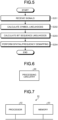
- FIG. 5 is a flowchart for explaining an operation of the wireless reception device 20 illustrated in FIG. 4 .
- the wireless reception device 20 receives signals at the receiving antenna 21 (step S201).
- the likelihood calculation unit 22 calculates symbol likelihoods each corresponding to one of the M number of FSK symbol candidates on the basis of frequency components of the reception signals received by the receiving antenna 21 (step S202).
- the likelihood calculation unit 22 outputs the plurality of symbol likelihoods to the demodulation unit 23.
- the demodulation unit 23 calculates bit sequence likelihoods corresponding to the M number of information bit sequence candidates on the basis of the plurality of symbol likelihoods and the mapping rule (step S203).
- the demodulation unit 23 obtains an estimation value b (hat) of the information bit sequence by performing a spatial/frequency demapping process (step S204). Specifically, the demodulation unit 23 obtains the estimation value b (hat) of the information bit sequence by performing maximum likelihood estimation based on the calculated bit sequence likelihoods.
- the mapping unit 11, the modulation units 12, the likelihood calculation unit 22, and the demodulation unit 23 are implemented by processing circuitry.
- the processing circuitry may be implemented by dedicated hardware, or may be a control circuit using a central processing unit (CPU).
- FIG. 6 is a diagram illustrating dedicated hardware for implementing the functions of the wireless transmission device 10 and the wireless reception device 20 according to the embodiment of the present invention.
- the processing circuitry 90 is a single circuit, a composite circuit, a programmed processor, a parallel programmed processor, an application specific integrated circuit (ASIC), a field programmable gate array (FPGA), or a combination thereof.
- FIG. 7 is a diagram illustrating a configuration of the control circuit 91 for implementing the functions of the wireless transmission device 10 and the wireless reception device 20 according to the embodiment of the present invention.
- the control circuit 91 includes a processor 92 and a memory 93.
- the processor 92 is a CPU, and also referred to as a central processing device, a processing device, an arithmetic device, a microprocessor, a microcomputer, a digital signal processor (DSP), or the like.
- the memory 93 is, for example, a non-volatile or volatile semiconductor memory such as a random access memory (RAM), a read only memory (ROM), a flash memory, an erasable programmable ROM (EPROM), or an electrically EPROM (EEPROM (registered trademark)), a magnetic disk, a flexible disk, an optical disk, a compact disc, a mini disk, or a digital versatile disk (DVD).
- RAM random access memory
- ROM read only memory
- EPROM erasable programmable ROM
- EEPROM electrically EPROM
- mapping unit 11 the functions of the mapping unit 11, the modulation units 12, the likelihood calculation unit 22, and the demodulation unit 23 are described as programs and stored in the memory 93.
- the functions of the mapping unit 11, the modulation units 12, the likelihood calculation unit 22, and the demodulation unit 23 are implemented by the processor 92 reading and executing a program stored in the memory 93.
- the memory 93 is also used as a temporary memory in each process executed by the processor 92.
- a part of the above functions may be implemented by dedicated hardware, and the rest thereof may be implemented by a program.
- the wireless transmission device 10 and the wireless reception device 20 have been described as devices separate from each other, but a wireless communication device having the functions of the wireless transmission device 10 and the wireless reception device 20 may be provided.
- the wireless communication device includes the mapping unit 11 provided in the preceding stage of the modulation units 12.
- the mapping unit 11 allocates the carrier waves such that the plurality of transmission signals each transmitted from one of the plurality of transmitting antennas 13 included in the wireless communication device are orthogonal to each other.
- the signals each transmitted from one of the transmitting antennas 13 are orthogonal to each other on the frequency axis, and thus, full diversity can be acquired in a case of N ⁇ M in which there occurs one-to-one correspondence of combinations of respective values of the bit sequence b and the carrier waves. Therefore, it is possible to achieve high transmission quality compared with a case of using a technique of cyclic delay diversity that provides delays different from each other to signals each transmitted from one of the plurality of antennas in block transmission to artificially create frequency selectivity.
- the orthogonality of the transmission signals from the transmitting antennas 13 is guaranteed in a closed form in one FSK modulation symbol. Therefore, it is possible to enhance resistance to a time variation of a communication path.
- initial phases allocated to the transmitting antennas 13 are different from each other. With such a configuration, it is possible to increase a minimum distance between signal points in a signal point space formed by bit sequence likelihoods as compared with a case where the initial phases are the same. Therefore, transmission quality can be improved.
- the present invention can also be used in combination with any secondary modulation technique such as orthogonal frequency-division multiplexing (OFDM) or direct sequence spread spectrum (DSSS), and high transmission quality which is an effect of the present invention can be achieved also in that case.
- OFDM orthogonal frequency-division multiplexing
- DSSS direct sequence spread spectrum
Landscapes
- Engineering & Computer Science (AREA)
- Computer Networks & Wireless Communication (AREA)
- Signal Processing (AREA)
- Radio Transmission System (AREA)
Claims (6)
- Drahtlos-Kommunikationseinrichtung (10), umfassend:eine Vielzahl von Übertragungsantennen (13);eine Vielzahl von Modulationseinheiten (12), die jeweils entsprechend einer der Vielzahl von Übertragungsantennen (13) vorgesehen sind, um Übertragungssignale zu erzeugen, die von den ihnen entsprechenden Übertragungsantennen (13) übertragen werden, indem eine Frequenzumtastung auf einer Trägerwelle auf der Grundlage von Übertragungsdaten durchgeführt wird; undeine Mapping-Einheit (11), die in einer vorangehenden Stufe der Vielzahl von Modulationseinheiten (12) vorgesehen ist,wobei die Mapping-Einheit (11) eingerichtet ist, an jede der Modulationseinheiten (12) eine Zahl zur Identifizierung einer Frequenzverschiebung auf der von jeder der Modulationseinheiten (12) verwendeten Trägerwelle in Abhängigkeit von einem Wert einer Eingangsbitfolge (b1b2) der Übertragungsdaten auszugeben, wobei die Zahlen, die von der Mapping-Einheit (11) auf der Grundlage der Eingangsbitfolge (b1b2) an die Vielzahl von Modulationseinheiten (12) ausgegeben werden, voneinander verschieden sind, so dass die Übertragungssignale, die jeweils von einer der Vielzahl von Übertragungsantennen übertragen werden, auf einer Frequenzachse orthogonal zueinander sind,wobei jede der Modulationseinheiten (12) eingerichtet ist, ein Übertragungssignal zu erzeugen, das von jeder der Übertragungseinheiten (13) übertragen wird, indem eine Frequenzumtastung auf der Trägerwelle auf der Grundlage der Zahl durchgeführt wird,wobei die Zahl zur Identifizierung einer Frequenzverschiebung auf der Trägerwelle, die an jede der Modulationseinheiten ausgegeben wird, auf der Grundlage eines minimalen Trägerintervalls bestimmt wird, bei dem zwei Trägerwellen orthogonal zueinander sind.
- Drahtlos-Kommunikationseinrichtung (10) nach Anspruch 1, wobei die Mapping-Einheit (11) eingerichtet ist, die Zahlen so zuzuordnen, dass Kombinationen der Zahlen, die jeweils einer der Vielzahl von Modulationseinheiten (12) zugeordnet sind, für alle Werte einer einzugebenden Informationsbitfolge unterschiedlich sind.
- Drahtlos-Kommunikationseinrichtung (10) nach Anspruch 1 oder 2, wobei die Modulationseinheiten (12) eingerichtet sind, der Vielzahl von Übertragungsantennen voneinander verschiedene Anfangsphasen von Modulationssymbolen zuzuordnen.
- Drahtlos-Kommunikationseinrichtung (20) nach einem der Ansprüche 1 bis 3, ferner umfassend einen Empfänger (22, 23), um eine Wahrscheinlichkeit aus einer Frequenzkomponente eines Empfangssymbols zu berechnen und eine Maximum-Likelihood-Schätzung auf der Grundlage einer Mapping-Regel durchzuführen, die eine Zuordnungsregel der Zahlen in der Mapping-Einheit (11) ist.
- Drahtlos-Kommunikationseinrichtung (10) nach einem der Ansprüche 1 bis 4, wobei die Mapping-Einheit (11) eingerichtet ist, eine Mapping-Regel zu definieren, die eine Zuordnungsregel der Zahlen auf der Grundlage einer Zahl von Antennen der Übertragungsantennen (13) und eines Modulationspegels und eines Modulationsindexes der Modulationseinheiten (12) ist.
- Drahtlos-Kommunikationsverfahren, das von einer drahtlosen Kommunikationseinrichtung (10, 20) ausgeführt wird, wobei die Drahtlos-Kommunikationseinrichtung (10, 20) umfasst: eine Vielzahl von Übertragungsantennen (13), eine Vielzahl von Modulationseinheiten (12), die jeweils entsprechend einer der Vielzahl von Übertragungsantennen (13) vorgesehen sind, um Übertragungssignale zu erzeugen, die von den ihnen entsprechenden Übertragungsantennen (13) übertragen werden, indem eine Frequenzumtastung auf einer Trägerwelle auf der Grundlage von Übertragungsdaten durchgeführt wird; und eine Mapping-Einheit (11), die in einer vorangehenden Stufe der Vielzahl von Modulationseinheiten (12) vorgesehen ist,
wobei das Verfahren die Schritte umfasst:Ausgeben, durch die Mapping-Einheit (11), an jede der Modulationseinheiten (12), einer Zahl zur Identifizierung einer Frequenzverschiebung auf der von jeder der Modulationseinheiten (12) verwendeten Trägerwelle in Abhängigkeit von einem Wert einer Eingangsbitfolge (b1b2) der Übertragungsdaten, wobei die Zahlen, die von der Mapping-Einheit (11) auf der Grundlage der Eingangsbitfolge (b1b2) an die Vielzahl von Modulationseinheiten (12) ausgegeben werden, voneinander verschieden sind, so dass die Übertragungssignale, die jeweils von einer der Vielzahl von Übertragungsantennen übertragen werden, auf einer Frequenzachse orthogonal zueinander sind, undErzeugen, durch die Modulationseinheiten (12), eines Übertragungssignals, das von jeder der Übertragungseinheiten (13) übertragen wird, indem eine Frequenzumtastung auf der Trägerwelle durchgeführt wird, auf der Grundlage der Zahl,wobei die Zahl zur Identifizierung einer Frequenzverschiebung auf der Trägerwelle, die an jede der Modulationseinheiten ausgegeben wird, auf der Grundlage eines minimalen Trägerintervalls bestimmt wird, bei dem zwei Trägerwellen orthogonal zueinander sind.
Applications Claiming Priority (1)
| Application Number | Priority Date | Filing Date | Title |
|---|---|---|---|
| PCT/JP2019/032710 WO2021033297A1 (ja) | 2019-08-21 | 2019-08-21 | 無線通信装置、制御回路、無線通信方法および記憶媒体 |
Publications (3)
| Publication Number | Publication Date |
|---|---|
| EP4007180A1 EP4007180A1 (de) | 2022-06-01 |
| EP4007180A4 EP4007180A4 (de) | 2022-08-17 |
| EP4007180B1 true EP4007180B1 (de) | 2024-11-27 |
Family
ID=71663967
Family Applications (1)
| Application Number | Title | Priority Date | Filing Date |
|---|---|---|---|
| EP19942021.7A Active EP4007180B1 (de) | 2019-08-21 | 2019-08-21 | Drahtlose kommunikationsvorrichtung, steuerschaltung, drahtloses kommunikationsverfahren und speichermedium |
Country Status (5)
| Country | Link |
|---|---|
| US (1) | US11764841B2 (de) |
| EP (1) | EP4007180B1 (de) |
| JP (1) | JP6727462B1 (de) |
| CN (1) | CN114245966A (de) |
| WO (1) | WO2021033297A1 (de) |
Families Citing this family (2)
| Publication number | Priority date | Publication date | Assignee | Title |
|---|---|---|---|---|
| CN117896224A (zh) * | 2022-10-09 | 2024-04-16 | 中兴通讯股份有限公司 | 微波传输系统、方法及存储介质 |
| CN116567866B (zh) * | 2023-05-23 | 2026-02-06 | 上海朗力半导体有限公司 | 无线数据中心系统、通信方法、电子设备及芯片 |
Citations (3)
| Publication number | Priority date | Publication date | Assignee | Title |
|---|---|---|---|---|
| WO2006027502A2 (fr) * | 2004-09-08 | 2006-03-16 | Comsis | Procede de codage et decodage spatio-temporel non coherent par modulation de frequence; codeur et decodeur mettant en œuvre un tel procede |
| KR20080022643A (ko) * | 2006-09-07 | 2008-03-12 | 삼성전자주식회사 | 다중 안테나 시스템의 송수신 장치 및 방법 |
| US20170085407A1 (en) * | 2000-06-13 | 2017-03-23 | Comcast Cable Communications, Llc | Data Routing for OFDM Transmission Based on Observed Node Capacities |
Family Cites Families (4)
| Publication number | Priority date | Publication date | Assignee | Title |
|---|---|---|---|---|
| JPS5573147A (en) * | 1978-11-25 | 1980-06-02 | Furukawa Electric Co Ltd:The | Multi-carrier communication method |
| JPS61136332A (ja) * | 1984-12-07 | 1986-06-24 | Nippon Telegr & Teleph Corp <Ntt> | 送信ダイバ−シテイ通信方式 |
| WO2016076002A1 (ja) * | 2014-11-13 | 2016-05-19 | 三菱電機株式会社 | 送信機および受信機 |
| CN108900222A (zh) * | 2018-07-25 | 2018-11-27 | 南京邮电大学 | 一种基于mimo系统的跳频通信方法 |
-
2019
- 2019-08-21 EP EP19942021.7A patent/EP4007180B1/de active Active
- 2019-08-21 CN CN201980099243.6A patent/CN114245966A/zh active Pending
- 2019-08-21 JP JP2019568281A patent/JP6727462B1/ja active Active
- 2019-08-21 WO PCT/JP2019/032710 patent/WO2021033297A1/ja not_active Ceased
-
2021
- 2021-12-01 US US17/539,643 patent/US11764841B2/en active Active
Patent Citations (3)
| Publication number | Priority date | Publication date | Assignee | Title |
|---|---|---|---|---|
| US20170085407A1 (en) * | 2000-06-13 | 2017-03-23 | Comcast Cable Communications, Llc | Data Routing for OFDM Transmission Based on Observed Node Capacities |
| WO2006027502A2 (fr) * | 2004-09-08 | 2006-03-16 | Comsis | Procede de codage et decodage spatio-temporel non coherent par modulation de frequence; codeur et decodeur mettant en œuvre un tel procede |
| KR20080022643A (ko) * | 2006-09-07 | 2008-03-12 | 삼성전자주식회사 | 다중 안테나 시스템의 송수신 장치 및 방법 |
Also Published As
| Publication number | Publication date |
|---|---|
| EP4007180A4 (de) | 2022-08-17 |
| US11764841B2 (en) | 2023-09-19 |
| JPWO2021033297A1 (ja) | 2021-09-13 |
| WO2021033297A1 (ja) | 2021-02-25 |
| EP4007180A1 (de) | 2022-06-01 |
| JP6727462B1 (ja) | 2020-07-22 |
| US20220094406A1 (en) | 2022-03-24 |
| CN114245966A (zh) | 2022-03-25 |
Similar Documents
| Publication | Publication Date | Title |
|---|---|---|
| AU2019200710B2 (en) | Multi-user code division multiple access communication method, and corresponding transmitter and receiver | |
| CN114747258B (zh) | 低峰值平均功率比的频域调制方案 | |
| US11764841B2 (en) | Wireless communication device, control circuit, wireless communication method, and storage medium | |
| AU2017278823A1 (en) | Method for demodulating a received signal, and corresponding computer program product and device | |
| WO2019163037A1 (ja) | 無線通信システムおよび無線通信方法 | |
| EP3249824B1 (de) | Datenübertragungsverfahren und -vorrichtung | |
| US20190312769A1 (en) | Transmission method, transmission device, reception method, and reception device | |
| US10411944B2 (en) | Transmission method, transmission device, reception method, and reception device | |
| US20080037686A1 (en) | Wireless transmission method using ofdm and transmitter and receiver thereof | |
| EP3697010B1 (de) | Datenverarbeitungsverfahren und -vorrichtung | |
| US20100246641A1 (en) | Time-frequency code spreading method and apparatus in ofdma system | |
| JP2009528753A (ja) | チャネルのコヒーレンス帯域幅に基づくofdmシステムにおける最大循環遅延の特定方法 | |
| JP2014165830A (ja) | 送信機、受信機および送信方法 | |
| Xu et al. | OFDM waveform design with good correlation level and peak-to-mean envelope power ratio for the joint MIMO radar and communications | |
| JP4719914B2 (ja) | 送信装置、受信装置、送信方法、受信方法、ならびに、プログラム | |
| US10938439B2 (en) | Two-phase transmission for machine-type communication | |
| US10880134B2 (en) | Reception device, reception method, and communication system | |
| JP7221457B2 (ja) | 送信装置、受信装置および基地局 | |
| EP3487092B1 (de) | Übertragungsvorrichtung und übertragungsverfahren | |
| EP4283889A1 (de) | Kommunikationsvorrichtung, kommunikationssystem, steuerschaltung, speichermedium und kommunikationsverfahren | |
| US20090129443A1 (en) | Multi-Channel Transmission System, Transmitting Apparatus and Transmitting Method | |
| WO2025243547A1 (ja) | 受信装置、受信方法、制御回路および記憶媒体 | |
| KR20100087675A (ko) | 직교주파수분할 다중접속방식 통신시스템에서 상향링크 제어채널을 통해 정보를 전송하기 위한 장치 및 방법 | |
| KR20090126518A (ko) | 직교 주파수 분할 다중 접속 기반 통신 시스템에서 고속피드백 정보 송수신 장치 및 방법 | |
| JP2011024160A (ja) | 受信装置及び軟判定誤り訂正復号方法 |
Legal Events
| Date | Code | Title | Description |
|---|---|---|---|
| STAA | Information on the status of an ep patent application or granted ep patent |
Free format text: STATUS: THE INTERNATIONAL PUBLICATION HAS BEEN MADE |
|
| PUAI | Public reference made under article 153(3) epc to a published international application that has entered the european phase |
Free format text: ORIGINAL CODE: 0009012 |
|
| STAA | Information on the status of an ep patent application or granted ep patent |
Free format text: STATUS: REQUEST FOR EXAMINATION WAS MADE |
|
| 17P | Request for examination filed |
Effective date: 20220211 |
|
| AK | Designated contracting states |
Kind code of ref document: A1 Designated state(s): AL AT BE BG CH CY CZ DE DK EE ES FI FR GB GR HR HU IE IS IT LI LT LU LV MC MK MT NL NO PL PT RO RS SE SI SK SM TR |
|
| A4 | Supplementary search report drawn up and despatched |
Effective date: 20220719 |
|
| RIC1 | Information provided on ipc code assigned before grant |
Ipc: H04L 27/26 20060101ALI20220713BHEP Ipc: H04L 27/12 20060101ALI20220713BHEP Ipc: H04L 1/06 20060101ALI20220713BHEP Ipc: H04L 27/10 20060101ALI20220713BHEP Ipc: H04B 7/12 20060101ALI20220713BHEP Ipc: H04B 7/06 20060101AFI20220713BHEP |
|
| DAV | Request for validation of the european patent (deleted) | ||
| DAX | Request for extension of the european patent (deleted) | ||
| STAA | Information on the status of an ep patent application or granted ep patent |
Free format text: STATUS: EXAMINATION IS IN PROGRESS |
|
| 17Q | First examination report despatched |
Effective date: 20230130 |
|
| GRAP | Despatch of communication of intention to grant a patent |
Free format text: ORIGINAL CODE: EPIDOSNIGR1 |
|
| STAA | Information on the status of an ep patent application or granted ep patent |
Free format text: STATUS: GRANT OF PATENT IS INTENDED |
|
| INTG | Intention to grant announced |
Effective date: 20240626 |
|
| GRAS | Grant fee paid |
Free format text: ORIGINAL CODE: EPIDOSNIGR3 |
|
| GRAA | (expected) grant |
Free format text: ORIGINAL CODE: 0009210 |
|
| STAA | Information on the status of an ep patent application or granted ep patent |
Free format text: STATUS: THE PATENT HAS BEEN GRANTED |
|
| AK | Designated contracting states |
Kind code of ref document: B1 Designated state(s): AL AT BE BG CH CY CZ DE DK EE ES FI FR GB GR HR HU IE IS IT LI LT LU LV MC MK MT NL NO PL PT RO RS SE SI SK SM TR |
|
| REG | Reference to a national code |
Ref country code: GB Ref legal event code: FG4D |
|
| REG | Reference to a national code |
Ref country code: CH Ref legal event code: EP |
|
| REG | Reference to a national code |
Ref country code: DE Ref legal event code: R096 Ref document number: 602019062804 Country of ref document: DE |
|
| REG | Reference to a national code |
Ref country code: IE Ref legal event code: FG4D |
|
| REG | Reference to a national code |
Ref country code: LT Ref legal event code: MG9D |
|
| REG | Reference to a national code |
Ref country code: NL Ref legal event code: MP Effective date: 20241127 |
|
| PG25 | Lapsed in a contracting state [announced via postgrant information from national office to epo] |
Ref country code: PT Free format text: LAPSE BECAUSE OF FAILURE TO SUBMIT A TRANSLATION OF THE DESCRIPTION OR TO PAY THE FEE WITHIN THE PRESCRIBED TIME-LIMIT Effective date: 20250327 Ref country code: HR Free format text: LAPSE BECAUSE OF FAILURE TO SUBMIT A TRANSLATION OF THE DESCRIPTION OR TO PAY THE FEE WITHIN THE PRESCRIBED TIME-LIMIT Effective date: 20241127 Ref country code: IS Free format text: LAPSE BECAUSE OF FAILURE TO SUBMIT A TRANSLATION OF THE DESCRIPTION OR TO PAY THE FEE WITHIN THE PRESCRIBED TIME-LIMIT Effective date: 20250327 |
|
| PG25 | Lapsed in a contracting state [announced via postgrant information from national office to epo] |
Ref country code: FI Free format text: LAPSE BECAUSE OF FAILURE TO SUBMIT A TRANSLATION OF THE DESCRIPTION OR TO PAY THE FEE WITHIN THE PRESCRIBED TIME-LIMIT Effective date: 20241127 Ref country code: NL Free format text: LAPSE BECAUSE OF FAILURE TO SUBMIT A TRANSLATION OF THE DESCRIPTION OR TO PAY THE FEE WITHIN THE PRESCRIBED TIME-LIMIT Effective date: 20241127 |
|
| REG | Reference to a national code |
Ref country code: AT Ref legal event code: MK05 Ref document number: 1746723 Country of ref document: AT Kind code of ref document: T Effective date: 20241127 |
|
| PG25 | Lapsed in a contracting state [announced via postgrant information from national office to epo] |
Ref country code: BG Free format text: LAPSE BECAUSE OF FAILURE TO SUBMIT A TRANSLATION OF THE DESCRIPTION OR TO PAY THE FEE WITHIN THE PRESCRIBED TIME-LIMIT Effective date: 20241127 |
|
| PG25 | Lapsed in a contracting state [announced via postgrant information from national office to epo] |
Ref country code: ES Free format text: LAPSE BECAUSE OF FAILURE TO SUBMIT A TRANSLATION OF THE DESCRIPTION OR TO PAY THE FEE WITHIN THE PRESCRIBED TIME-LIMIT Effective date: 20241127 |
|
| PG25 | Lapsed in a contracting state [announced via postgrant information from national office to epo] |
Ref country code: NO Free format text: LAPSE BECAUSE OF FAILURE TO SUBMIT A TRANSLATION OF THE DESCRIPTION OR TO PAY THE FEE WITHIN THE PRESCRIBED TIME-LIMIT Effective date: 20250227 |
|
| PG25 | Lapsed in a contracting state [announced via postgrant information from national office to epo] |
Ref country code: LV Free format text: LAPSE BECAUSE OF FAILURE TO SUBMIT A TRANSLATION OF THE DESCRIPTION OR TO PAY THE FEE WITHIN THE PRESCRIBED TIME-LIMIT Effective date: 20241127 Ref country code: GR Free format text: LAPSE BECAUSE OF FAILURE TO SUBMIT A TRANSLATION OF THE DESCRIPTION OR TO PAY THE FEE WITHIN THE PRESCRIBED TIME-LIMIT Effective date: 20250228 Ref country code: AT Free format text: LAPSE BECAUSE OF FAILURE TO SUBMIT A TRANSLATION OF THE DESCRIPTION OR TO PAY THE FEE WITHIN THE PRESCRIBED TIME-LIMIT Effective date: 20241127 |
|
| PG25 | Lapsed in a contracting state [announced via postgrant information from national office to epo] |
Ref country code: PL Free format text: LAPSE BECAUSE OF FAILURE TO SUBMIT A TRANSLATION OF THE DESCRIPTION OR TO PAY THE FEE WITHIN THE PRESCRIBED TIME-LIMIT Effective date: 20241127 |
|
| PG25 | Lapsed in a contracting state [announced via postgrant information from national office to epo] |
Ref country code: RS Free format text: LAPSE BECAUSE OF FAILURE TO SUBMIT A TRANSLATION OF THE DESCRIPTION OR TO PAY THE FEE WITHIN THE PRESCRIBED TIME-LIMIT Effective date: 20250227 |
|
| PG25 | Lapsed in a contracting state [announced via postgrant information from national office to epo] |
Ref country code: SM Free format text: LAPSE BECAUSE OF FAILURE TO SUBMIT A TRANSLATION OF THE DESCRIPTION OR TO PAY THE FEE WITHIN THE PRESCRIBED TIME-LIMIT Effective date: 20241127 |
|
| PG25 | Lapsed in a contracting state [announced via postgrant information from national office to epo] |
Ref country code: DK Free format text: LAPSE BECAUSE OF FAILURE TO SUBMIT A TRANSLATION OF THE DESCRIPTION OR TO PAY THE FEE WITHIN THE PRESCRIBED TIME-LIMIT Effective date: 20241127 |
|
| PG25 | Lapsed in a contracting state [announced via postgrant information from national office to epo] |
Ref country code: EE Free format text: LAPSE BECAUSE OF FAILURE TO SUBMIT A TRANSLATION OF THE DESCRIPTION OR TO PAY THE FEE WITHIN THE PRESCRIBED TIME-LIMIT Effective date: 20241127 |
|
| PG25 | Lapsed in a contracting state [announced via postgrant information from national office to epo] |
Ref country code: RO Free format text: LAPSE BECAUSE OF FAILURE TO SUBMIT A TRANSLATION OF THE DESCRIPTION OR TO PAY THE FEE WITHIN THE PRESCRIBED TIME-LIMIT Effective date: 20241127 |
|
| PG25 | Lapsed in a contracting state [announced via postgrant information from national office to epo] |
Ref country code: SK Free format text: LAPSE BECAUSE OF FAILURE TO SUBMIT A TRANSLATION OF THE DESCRIPTION OR TO PAY THE FEE WITHIN THE PRESCRIBED TIME-LIMIT Effective date: 20241127 |
|
| PG25 | Lapsed in a contracting state [announced via postgrant information from national office to epo] |
Ref country code: CZ Free format text: LAPSE BECAUSE OF FAILURE TO SUBMIT A TRANSLATION OF THE DESCRIPTION OR TO PAY THE FEE WITHIN THE PRESCRIBED TIME-LIMIT Effective date: 20241127 |
|
| PG25 | Lapsed in a contracting state [announced via postgrant information from national office to epo] |
Ref country code: IT Free format text: LAPSE BECAUSE OF FAILURE TO SUBMIT A TRANSLATION OF THE DESCRIPTION OR TO PAY THE FEE WITHIN THE PRESCRIBED TIME-LIMIT Effective date: 20241127 |
|
| REG | Reference to a national code |
Ref country code: DE Ref legal event code: R097 Ref document number: 602019062804 Country of ref document: DE |
|
| PG25 | Lapsed in a contracting state [announced via postgrant information from national office to epo] |
Ref country code: SE Free format text: LAPSE BECAUSE OF FAILURE TO SUBMIT A TRANSLATION OF THE DESCRIPTION OR TO PAY THE FEE WITHIN THE PRESCRIBED TIME-LIMIT Effective date: 20241127 |
|
| P01 | Opt-out of the competence of the unified patent court (upc) registered |
Free format text: CASE NUMBER: UPC_APP_4942_4007180/2025 Effective date: 20250827 |
|
| PLBE | No opposition filed within time limit |
Free format text: ORIGINAL CODE: 0009261 |
|
| STAA | Information on the status of an ep patent application or granted ep patent |
Free format text: STATUS: NO OPPOSITION FILED WITHIN TIME LIMIT |
|
| REG | Reference to a national code |
Ref country code: CH Ref legal event code: L10 Free format text: ST27 STATUS EVENT CODE: U-0-0-L10-L00 (AS PROVIDED BY THE NATIONAL OFFICE) Effective date: 20251008 |
|
| PGFP | Annual fee paid to national office [announced via postgrant information from national office to epo] |
Ref country code: DE Payment date: 20250702 Year of fee payment: 7 |
|
| PGFP | Annual fee paid to national office [announced via postgrant information from national office to epo] |
Ref country code: GB Payment date: 20250703 Year of fee payment: 7 |
|
| PGFP | Annual fee paid to national office [announced via postgrant information from national office to epo] |
Ref country code: FR Payment date: 20250703 Year of fee payment: 7 |
|
| 26N | No opposition filed |
Effective date: 20250828 |
|
| REG | Reference to a national code |
Ref country code: CH Ref legal event code: H13 Free format text: ST27 STATUS EVENT CODE: U-0-0-H10-H13 (AS PROVIDED BY THE NATIONAL OFFICE) Effective date: 20260324 |
|
| PG25 | Lapsed in a contracting state [announced via postgrant information from national office to epo] |
Ref country code: MC Free format text: LAPSE BECAUSE OF FAILURE TO SUBMIT A TRANSLATION OF THE DESCRIPTION OR TO PAY THE FEE WITHIN THE PRESCRIBED TIME-LIMIT Effective date: 20241127 |
|
| PG25 | Lapsed in a contracting state [announced via postgrant information from national office to epo] |
Ref country code: LU Free format text: LAPSE BECAUSE OF NON-PAYMENT OF DUE FEES Effective date: 20250821 |
|
| PG25 | Lapsed in a contracting state [announced via postgrant information from national office to epo] |
Ref country code: CH Free format text: LAPSE BECAUSE OF NON-PAYMENT OF DUE FEES Effective date: 20250831 |