EP4007202B1 - Ressourcenkonfigurationsverfahren und -vorrichtung - Google Patents
Ressourcenkonfigurationsverfahren und -vorrichtung Download PDFInfo
- Publication number
- EP4007202B1 EP4007202B1 EP20850106.4A EP20850106A EP4007202B1 EP 4007202 B1 EP4007202 B1 EP 4007202B1 EP 20850106 A EP20850106 A EP 20850106A EP 4007202 B1 EP4007202 B1 EP 4007202B1
- Authority
- EP
- European Patent Office
- Prior art keywords
- node
- resource configuration
- resource
- configuration
- terminal device
- Prior art date
- Legal status (The legal status is an assumption and is not a legal conclusion. Google has not performed a legal analysis and makes no representation as to the accuracy of the status listed.)
- Active
Links
Images


Classifications
-
- H—ELECTRICITY
- H04—ELECTRIC COMMUNICATION TECHNIQUE
- H04L—TRANSMISSION OF DIGITAL INFORMATION, e.g. TELEGRAPHIC COMMUNICATION
- H04L5/00—Arrangements affording multiple use of the transmission path
- H04L5/0001—Arrangements for dividing the transmission path
- H04L5/0003—Two-dimensional division
- H04L5/0005—Time-frequency
- H04L5/0007—Time-frequency the frequencies being orthogonal, e.g. OFDM(A) or DMT
- H04L5/001—Time-frequency the frequencies being orthogonal, e.g. OFDM(A) or DMT the frequencies being arranged in component carriers
-
- H—ELECTRICITY
- H04—ELECTRIC COMMUNICATION TECHNIQUE
- H04L—TRANSMISSION OF DIGITAL INFORMATION, e.g. TELEGRAPHIC COMMUNICATION
- H04L5/00—Arrangements affording multiple use of the transmission path
- H04L5/14—Two-way operation using the same type of signal, i.e. duplex
- H04L5/1469—Two-way operation using the same type of signal, i.e. duplex using time-sharing
-
- H—ELECTRICITY
- H04—ELECTRIC COMMUNICATION TECHNIQUE
- H04W—WIRELESS COMMUNICATION NETWORKS
- H04W72/00—Local resource management
- H04W72/20—Control channels or signalling for resource management
-
- H—ELECTRICITY
- H04—ELECTRIC COMMUNICATION TECHNIQUE
- H04L—TRANSMISSION OF DIGITAL INFORMATION, e.g. TELEGRAPHIC COMMUNICATION
- H04L5/00—Arrangements affording multiple use of the transmission path
- H04L5/0091—Signalling for the administration of the divided path, e.g. signalling of configuration information
- H04L5/0094—Indication of how sub-channels of the path are allocated
-
- H—ELECTRICITY
- H04—ELECTRIC COMMUNICATION TECHNIQUE
- H04B—TRANSMISSION
- H04B7/00—Radio transmission systems, i.e. using radiation field
- H04B7/14—Relay systems
- H04B7/15—Active relay systems
- H04B7/155—Ground-based stations
- H04B7/15528—Control of operation parameters of a relay station to exploit the physical medium
- H04B7/15542—Selecting at relay station its transmit and receive resources
Definitions
- This application relates to the communication field, and more specifically, to a resource configuration method and apparatus, and a computer-readable storage medium.
- an access network device implements a connection between a terminal device and a core network by using an optical fiber.
- optical fiber deployment is costly in many scenarios. Therefore, an integrated access and backhaul (integrated access and backhaul node, IAB) technology may be used to implement a connection to the core network through a wireless backhaul link between a relay device and the access network device, to avoid high costs caused by deploying a large quantity of optical fibers.
- IAB integrated access and backhaul node
- a resource configuration of a relay device is consistent with a resource configuration of a terminal device that serves as a lower-level node of the relay device in the LTE system.
- a resource configuration of a relay device is complex, and a function of multiplexing a plurality of resources may need to be supported. Consequently, the resource configuration of the relay device in the LTE system is not applicable to the NR system.
- the document R1-1906001, 3GPP TSG RAN WG1 Meeting #97, Reno, USA, 13th - 17th May, 2019 refers to a resource multiplexing between backhaul and access in IAB.
- a long term evolution (long term evolution, LTE) system a worldwide interoperability for microwave access (worldwide interoperability for microwave access, WiMAX) communication system
- a future 5th generation (5th generation, 5G) system such as a new generation radio access technology (new radio access technology, NR)
- a future communication system such as a 6G system.
- information information
- a signal signal
- a message messages
- a channel channel
- expressed meanings are consistent when differences are not emphasized.
- “Relevant (relevant)” and “corresponding (corresponding)” may be interchangeably used sometimes. It should be noted that expressed meanings are consistent when differences are not emphasized.
- a network architecture and a service scenario described in the embodiments of this application are intended to describe the technical solutions in the embodiments of this application more clearly, and do not constitute any limitation on the technical solutions provided in the embodiments of this application.
- a person of ordinary skill in the art may know that with evolution of the network architecture and emergence of a new service scenario, the technical solutions provided in the embodiments of this application are also applicable to a similar technical problem.
- Non-cell Non-cell network architecture is introduced to the UE-centric network.
- a large quantity of small cells are deployed in a specific area to form a hyper cell (hyper cell).
- Each small cell is a transmission point (transmission point, TP) or a transmission reception point (transmission and reception point, TRP) of the hyper cell, and is connected to a centralized controller (controller).
- a network side device selects a new sub-cluster (sub-cluster) for the UE in real time to serve the UE, to avoid a real cell handover, and implement UE service continuity.
- the network side device includes a wireless network device.
- a plurality of network side devices such as small cells may have independent controllers such as distributed controllers. Each small cell can independently schedule a user, and information is exchanged between small cells for a long time, so that the small cell can provide a coordinated service for the UE flexibly to some extent.
- different base stations may be base stations having different identifiers, or may be base stations that have a same identifier and that are deployed at different geographical locations.
- a base station does not know whether the base station is related to a scenario to which the embodiments of this application are applied. Therefore, before being deployed, the base station or a baseband chip needs to support a method provided in the embodiments of this application. It may be understood that the foregoing base stations having different identifiers may have base station identifications, cell identifiers, or other identifiers.
- an NR network scenario in a wireless communication network is used as an example to describe some scenarios. It should be noted that the solutions in the embodiments of this application may further be applied to another wireless communication network, and a corresponding name may also be replaced with a name of a corresponding function in the another wireless communication network.
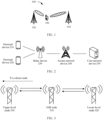
- FIG. 1 is a schematic diagram of a communication system to which embodiments of this application are applicable.
- the communication system 100 includes a network device 102 and a terminal device 106.
- the network device 102 may have a plurality of antennas, and the terminal device may also have a plurality of antennas.
- the communication system may further include a network device 104, and the network device 104 may also have a plurality of antennas.
- the network device 102 or the network device 104 may further include a plurality of components (for example, a processor, a modulator, a multiplexer, a demodulator, or a de-multiplexer) related to signal sending and receiving.
- a processor for example, a processor, a modulator, a multiplexer, a demodulator, or a de-multiplexer
- the network device is a device that has a wireless transceiver function or a chip that can be disposed in the device.
- the device includes but is not limited to an evolved NodeB (evolved NodeB, eNB), a radio network controller (radio network controller, RNC), a NodeB (NodeB, NB), a base station controller (base station controller, BSC), a base transceiver station (base transceiver station, BTS), a home base station (for example, a home evolved NodeB, or a home NodeB, HNB), a baseband unit (baseband unit, BBU), an access point (access point, AP), a wireless relay node, a wireless backhaul node, a transmission point (for example, a transmission reception point TRP or a transmission point TP), and the like in a wireless fidelity (wireless fidelity, Wi-Fi) system.
- eNB evolved NodeB
- RNC radio network controller
- NodeB NodeB
- the device may alternatively be a gNB or a transmission point (TRP or TP) in a 5G, such as NR, system, one or a group of (including a plurality of antenna panels) antenna panels of a base station in a 5G system, a network node that constitutes a gNB or a transmission point, for example, a baseband unit (base band unit, BBU) or a distributed unit (distributed unit, DU), or the like.
- a baseband unit base band unit, BBU
- DU distributed unit
- the gNB may include a centralized unit (centralized unit, CU) and a DU.
- the gNB may further include a radio unit (radio unit, RU).
- the CU implements some functions of the gNB
- the DU implements some functions of the gNB.
- the CU implements functions of a radio resource control (radio resource control, RRC) layer and a packet data convergence protocol (packet data convergence protocol, PDCP) layer
- the DU implements functions of a radio link control (radio link control, RLC) layer, a media access control (media access control, MAC) layer, and a physical (physical, PHY) layer.
- RRC radio resource control
- PDCP packet data convergence protocol
- the DU implements functions of a radio link control (radio link control, RLC) layer, a media access control (media access control, MAC) layer, and a physical (physical, PHY) layer.
- the network device may be a CU node, a DU node, or a device including the CU node and the DU node.
- the CU may serve as a network device in a radio access network RAN, or the CU may serve as a network device in a core network CN. This is not limited herein.
- the terminal device may also be referred to as user equipment (user equipment, UE), an access terminal, a subscriber unit, a subscriber station, a mobile station, a remote station, a remote terminal, a mobile device, a user terminal, a terminal, radio communication equipment, a user agent, a user apparatus, or the like.
- user equipment user equipment
- UE user equipment
- an access terminal a subscriber unit, a subscriber station, a mobile station, a remote station, a remote terminal, a mobile device, a user terminal, a terminal, radio communication equipment, a user agent, a user apparatus, or the like.
- the terminal device may be a mobile phone (mobile phone), a tablet computer (pad), a computer having a wireless transceiver function, a virtual reality (virtual reality, VR) terminal device, an augmented reality (augmented reality, AR) terminal device, a wireless terminal in industrial control (industrial control), a wireless terminal in self driving (self driving), a wireless terminal in telemedicine (remote medical), a wireless terminal in a smart grid (smart grid), a wireless terminal in transportation safety (transportation safety), a wireless terminal in a smart city (smart city), a wireless terminal in a smart home (smart home), or the like.
- An application scenario is not limited in the embodiments of this application.
- a terminal device having a wireless transceiver function and a chip that can be disposed in the foregoing terminal device are collectively referred to as a terminal device.
- the terminal device may alternatively be a wearable device.
- the wearable device may also be referred to as a wearable intelligent device, and is a general term of wearable devices, such as glasses, gloves, watches, clothes, and shoes, that are developed by applying wearable technologies to intelligent designs of daily wear.
- the wearable device is a portable device that can be directly worn by a user or integrated into clothes or an accessory of a user.
- the wearable device is not only a hardware device, but also implements a powerful function through software support, a data exchange, and cloud interaction.
- Generalized wearable intelligent devices include full-featured and large-size devices that can implement complete or partial functions without depending on smartphones, for example, smart watches or smart glasses, and devices that focus on only one type of application function and need to work with other devices such as smartphones, for example, various smart bands or smart jewelry for monitoring physical signs.
- the network device 102 and the network device 104 each may communicate with a plurality of terminal devices (for example, the terminal device 106 shown in the figure).
- the network device 102 and the network device 104 may communicate with one or more terminal devices similar to the terminal device 106.
- a terminal device communicating with the network device 102 and a terminal device communicating with the network device 104 may be the same or may be different.
- the terminal device 106 shown in FIG. 1 may simultaneously communicate with the network device 102 and the network device 104, but this shows only a possible scenario. In some scenarios, the terminal device may communicate with only the network device 102 or the network device 104. This is not limited in this application.
- FIG. 1 is merely a simplified schematic diagram used as an example for ease of understanding.
- the communication system may further include another network device or another terminal device that is not shown in FIG. 1 .
- an access network device implements a connection between a terminal device and a core network by using an optical fiber.
- optical fiber deployment is costly in many scenarios. Therefore, an integrated access and backhaul (integrated access and backhaul node, IAB) technology may be used to implement a connection to the core network through a wireless backhaul link between a relay device and the access network device, to avoid high costs caused by deploying a large quantity of optical fibers.
- IAB integrated access and backhaul node
- FIG. 2 is a schematic diagram of an architecture of a possible mobile communication system 200 having a relay device according to an embodiment of this application.
- the mobile communication system 200 includes at least one terminal device (for example, a terminal device 210 and a terminal device 220 in FIG. 2 ), a relay device 230, an access network device 240, and a core network device 250.
- the terminal device (for example, the terminal device 210 and the terminal device 220) may be connected to the relay device 230 in a wireless manner.
- One or more relay devices 230 may be connected to the access network device 240 in a wireless manner.
- the one or more relay devices 230 may be directly connected to the access network device 240, or may be indirectly connected to the access network device 240 through another relay device.
- the access network device 240 may be connected to the core network device 250 in a wireless manner, or may be connected to the core network device 250 in a wired manner. This is not specifically limited in this embodiment of this application.
- a type of the access network device 240 is not specifically limited in this embodiment of this application, and may be any device configured to communicate with the terminal device.
- the access network device 240 may be, for example, a base transceiver station (base transceiver station, BTS) in a global system for mobile communications (global system of mobile communication, GSM) system or a code division multiple access (code division multiple access, CDMA) system, a NodeB (NodeB, NB) in a wideband code division multiple access (wideband code division multiple access, WCDMA) system, an evolved NodeB (evolutional NodeB, eNB or eNodeB) in an LTE system, or a radio controller in a cloud radio access network (cloud radio access network, CRAN) scenario.
- BTS base transceiver station
- GSM global system of mobile communication
- CDMA code division multiple access
- NodeB NodeB
- WCDMA wideband code division multiple access
- WCDMA wideband code division multiple access
- the access network device 240 may be, for example, a relay station, an access point, a vehicle-mounted device, a wearable device, a network device in a future 5G network, or a network device in a future evolved PLMN network.
- a future access network may be implemented by using a cloud radio access network (cloud radio access network, C-RAN) architecture
- a protocol stack architecture and a function of a conventional access network device 140 are divided into two parts, one part is a CU, and the other part is a DU.
- One CU may be connected to one DU, or a plurality of DUs may share one CU, to reduce costs and facilitate network extension.
- the access network device 240 may provide a service for a cell, and the terminal device communicates with the access network device 240 by using a transmission resource (for example, a frequency domain resource, namely, a spectrum resource) used in the cell.
- the cell may be a cell corresponding to the access network device 240 (for example, a base station).
- the cell may belong to a macro base station, or may belong to a base station corresponding to a small cell (small cell).
- the small cell herein may include a metro cell (metro cell), a micro cell (micro cell), a pico cell (pico cell), a femto cell (femto cell), and the like. These small cells are characterized by small coverage and low transmit power, and are applicable to providing a high-rate data transmission service.
- the core network device 250 may be an evolved packet core network (evolved packet core network, EPC), and includes functional entities such as a serving gateway (serving gateway, S-GW) and a mobility management entity (mobility management entity, MME) of a mobile terminal.
- EPC evolved packet core network
- S-GW serving gateway
- MME mobility management entity
- the core network device 250 may be a next generation core network (next generation core network, NGC), and includes functional entities such as a session management function (session management function, SMF) and an access and mobility management function (access and mobility management function, AMF) to provide functions such as authentication and mobility management for a mobile terminal.
- NGC next generation core network
- SMF session management function
- AMF access and mobility management function
- the core network device 250 and the access network device 240 may be independent and different physical devices, functions of the core network device 250 and logical functions of the access network device 240 may be integrated into a same physical device, or some functions of the core network device 250 and some functions of the access network device 2140 may be integrated into one physical device.
- the terminal device may be at a fixed location, or may be mobile.
- a quantity of core network devices 250, a quantity of access network devices 2140, a quantity of relay devices 230, and a quantity of terminal devices included in the mobile communication system 200 are not limited in this embodiment of this application.
- the access network device 240 and the terminal device may be deployed on land, including an indoor device, an outdoor device, a handheld device, or a vehicle-mounted device; may be deployed on water; or may be deployed on an airplane, a balloon, and a satellite in the air.
- Application scenarios of the access network device 240 and the terminal device are not limited in the embodiments of this application.
- Communication between the access network device 240 and the terminal device and communication between the terminal devices may be performed by using a licensed spectrum (licensed spectrum), an unlicensed spectrum (unlicensed spectrum), or both a licensed spectrum and an unlicensed spectrum.
- Communication between the access network device 240 and the terminal device and communication between the terminal devices may be performed by using a spectrum below 6 gigahertz (gigahertz, GHz), may be performed by using a spectrum above 6 GHz, or may be performed by using both a spectrum below 6 GHz and a spectrum above 6 GHz.
- a spectrum resource used between the access network device 240 and the terminal device is not limited in this embodiment of this application.
- the relay device 230 may be referred to as an IAB node (IAB node), may be referred to as a relay node (relay node, RN), or may be referred to as a relay transmission reception point (relay transmitting receiving point, RTRP). This is not specifically limited in this application.
- the relay device 230 may forward data and/or signaling between the terminal device and the access network device 240.
- the relay device is referred to as an IAB node in the following to describe the embodiments of this application.
- the relay device 230 may include one or more IAB nodes.
- An IAB node 310 may establish a wireless backhaul link to one or more upper-level nodes 320, and access a donor (donor) base station through the one or more upper-level nodes 330.
- one IAB node may provide services for one or more lower-level nodes.
- the donor base station may be an access network element having a complete base station function, or may be an access network element in a form in which a centralized unit CU and a distributed unit DU are separated.
- the donor base station may also be referred to as an IAB donor or a donor node.
- the donor base station In a new radio (new radio, RN) system (or referred to as a 5G system), the donor base station may be a donor gNodeB (donor gNodeB, DgNB).
- donor gNodeB donor gNodeB
- DgNB donor gNodeB
- LTE Long Term Evolution
- the donor base station may be a donor eNodeB (donor eNodeB, DeNB).
- the donor base station may also be referred to as a gNB or an eNB for short.
- An example in which the donor base station is the access network device 240.
- One IAB node may access the access network device 240 through one or more upper-level nodes and is connected to the core network device 250, and the access network device 240 provides a wireless access function for the IAB node.
- An upper-level node of one IAB node 310 may be a donor base station, or may be another IAB node.
- a lower-level node of one IAB node 310 may be a terminal device, or may be another IAB node.
- a link for communication between the IAB node 310 and the upper-level node may be referred to as a parent backhaul link (parent backhaul link, parent BH link).
- a link for communication between the IAB node 310 and the lower-level IAB node may be referred to as a child backhaul link (child backhaul link, child BH link).
- a link for communication between the IAB node 310 and a lower-level terminal device may be referred to as an access link (access link).
- the child backhaul link (child BH link) may also be referred to as an access link.
- the upper-level node may also be referred to as an upstream node or a parent node.
- the lower-level node may be referred to as a downstream node or a child node. This is not specifically limited in this application.
- the IAB node 310 may serve as an access network device similar to a base station, and provide a service for the lower-level node of the IAB node 310 by using a plurality of types of signaling on an available air interface resource managed by the donor base station.
- the service may include but is not limited to data scheduling, timing modulation, power control, and the like.
- the IAB node 310 may serve as a terminal device for a parent node that provides a service for the IAB node 310, access a wireless network like the terminal device, and perform a function of the terminal device.
- the IAB node 310 establishes a connection to the parent node and obtains the service provided by the parent node for the IAB node 310 through operations such as cell selection and random access.
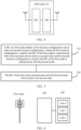
- a schematic diagram of a structure of the IAB node 310 is that shown in FIG. 4 .
- a part of the IAB node 310 that performs the function of the terminal device may be referred to as a mobile terminal (mobile terminal, MT) side or an MT functional module, and the IAB node 310 communicates with an upper-level node through an MT.
- a part of the IAB node 310 that serves as the access network device similar to the base station is referred to as a distributed unit (distributed unit, DU) side or a DU functional module, and the IAB node 310 may communicate with a lower-level node through a DU.
- the MT and the DU of the IAB node both may have complete transceiver modules, and there is an interface between the MT and the DU.
- the MT and the DU are logical modules.
- the MT and the DU may share some submodules, for example, may share a transceiver antenna and a baseband processing module.
- a resource configuration of the IAB node may include an MT resource configuration and a DU resource configuration.
- the MT resource configuration is used to indicate a resource configuration used when the MT of the IAB node communicates with the upper-level node, and an MT resource of the IAB node may be set to three types: uplink (uplink, U), downlink (downlink, D), and flexible (flexible, F).
- the IAB node in addition to supporting a function of multiplexing a plurality of resources, the IAB node may further ensure compatibility with existing UE.
- the following describes in detail the method provided in the embodiments of this application with reference to FIG. 4 .
- FIG. 5 is a schematic flowchart of a resource configuration method according to an embodiment of this application. As shown in FIG. 5 , the method may include steps 510 and 520. The following separately describes steps 510 and 520 in detail.
- the DU of the first node may correspond to the DU of the IAB node in the foregoing descriptions.
- the relay node may be an IAB node, or may be a terminal device.
- the first node and the second node are relay nodes in the wireless communication system.
- the DU of the first node may obtain the first resource configuration from a third node, where the third node may be a parent node or a donor node of the first node.
- the first resource configuration may be directly configured by the third node for the first node.
- the third node directly sends first resource configuration information to the first node by using an interface message (for example, F1 application process protocol (application process, F1-AP) interface signaling).
- the first node may implicitly infer the first resource configuration information from remaining information.
- the first node infers the first resource configuration information based on a time division duplex (time division duplexing, TDD) broadcast or unicast configuration sent by the third node.
- TDD time division duplexing
- the DU of the first node obtains the at least one second resource configuration. This is not specifically limited in this embodiment of this application.
- the DU of the first node may directly receive the at least one second resource configuration from the third node.
- the DU of the first node may further generate the at least one second resource configuration based on the first resource configuration received from the third node. For example, a resource type in the first resource configuration may be modified to obtain the at least one second resource configuration.
- the first resource configuration in this embodiment of this application may also be referred to as a reference resource configuration, and is used by the DU of the first node to communicate with the terminal device, used by the DU of the first node to communicate with the second node, or used by the DU of the first node to communicate with the terminal device and the second node.
- the second resource configuration may be referred to as an additional resource configuration, and is used by the DU of the first node to communicate with the second node.
- the second node is a child node of the first node, and the second node may include but is not limited to an IAB node and a special terminal device.
- the special terminal device may be a terminal device supporting a specific NR protocol release, for example, a terminal device supporting the NR Release 17.
- the terminal device may be a common terminal device.
- the terminal device may be a terminal device supporting a protocol release such as the NR Release 15/16/17.
- the DU of the first node has a plurality of cells (cells).
- the DU of the first node has panels or sectors in a plurality of directions, and different panels or sectors may be different cells.
- the DU of the first node uses a carrier aggregation manner, and different carriers may be different cells.
- An example in which the DU of the first node shown in FIG. 6 has a plurality of cells is used.
- the left figure shows a possible form of the first node having plurality of cells, that is, the first node has three antenna panels in different directions, and each panel is one cell.
- the right figure shows a schematic diagram of a structure of a DU having a plurality of cells and an MT.
- one or more of the plurality of cells may obtain only the first resource configuration, or may obtain both the first resource configuration and the second resource configuration. This is not specifically limited in this application.
- each cell may have an independent resource configuration, or may share a resource configuration.
- this embodiment of this application mainly describes a resource configuration of a cell in the DU of the first node.
- Step 520 The DU of the first node communicates with the terminal device and/or the second node.
- That the DU of the first node communicates with the terminal device and/or the second node may include one or more of the following cases: The DU of the first node communicates with the terminal device based on the first resource configuration. The DU of the first node communicates with the terminal device and/or the second node based on the first resource configuration. The DU of the first node communicates with the second node based on the second resource configuration. That is, the DU of the first node may select different resource configurations for communication based on a user type of a lower-level node of the first node. For example, when the lower-level node of the first node is a terminal device, the DU of the first node may communicate with the terminal device based on the first resource configuration.
- the DU of the first node may communicate with the second node based on the first resource configuration, or the DU of the first node may further communicate with the second node based on the second resource configuration.
- the DU of the first node may obtain at least two DU resource configurations, and different DU resource configurations correspond to different users. Different user types are distinguished by using different resource configurations, so that the DU of the first node uses appropriate resource configurations when communicating with different users. In addition to supporting a function of multiplexing a plurality of resources, compatibility with existing UE may further be ensured.
- the first resource configuration and the second resource configuration may have opposite slots or symbols. Therefore, the DU of the first node cannot simultaneously use the first resource configuration and the second resource configuration.
- the DU of the first node may use the first resource configuration and the second resource configuration in a time division manner.
- the first resource configuration and the second resource configuration may be preconfigured time division modes. That is, a correspondence between the first resource configuration, the second resource configuration, and a time unit is preconfigured in advance.
- the DU of the first node in a first time unit, a second time unit, or a third time unit, may communicate with the lower-level node based on the first resource configuration, and in the third time unit, the DU of the first node may communicate with the lower-level node based on the second resource configuration.
- the DU of the first node may select, based on the user type of the lower-level node, a resource configuration for communicating with a user, and communicate with the lower-level node in a corresponding time unit by using the resource configuration.
- a preconfiguration time division mode and a dynamic configuration time division mode may coexist.
- correspondences between the first resource configuration, the second resource configuration, and some time units are preconfigured in advance, and the first resource configuration and the second resource configuration are dynamically selected by the DU in some time units.
- time unit in this application may be a slot or a symbol, or may be a TDD pattern periodicity. This is not specifically limited in this application.
- the DU of the first node may select different resource configurations for communication based on the user type of the lower-level node of the first node.
- the DU of the first node may group lower-level nodes communicating with the first node, and use different types of resource configurations for different user groups. There are a plurality of specific implementations for grouping the lower-level nodes. This is not specifically limited in this application.
- the terminal device belongs to a user group 1, and the second node belongs to a user group 2.
- the DU of the first node uses the first resource configuration.
- the DU of the first node uses the second resource configuration.
- the terminal device belongs to a user group 1, and the second node belongs to a user group 2.
- the DU of the first node uses the first resource configuration.
- the DU of the first node may use the first resource configuration, or may use the second resource configuration.
- the terminal device and the second node belong to a user group 1 by default, and an upper-level node or a donor node of the first node may configure some second nodes in the user group 1 to belong to a user group 2.
- the DU of the first node uses the first resource configuration.
- the DU of the first node may use the first resource configuration, or may use the second resource configuration.
- the terminal device belongs to a user group 1, and the second node belongs to a user group 2 by default.
- An upper-level node or a donor node of the first node may configure some second nodes in the user group 1 to belong to the user group 2, or configure some second nodes in the user group 2 to belong to the user group 1.
- the DU of the first node uses the first resource configuration.
- the DU of the first node may use the first resource configuration, or may use the second resource configuration.
- users may be further divided into three groups.
- a user in a user group 1 can communicate with the DU of the first node only by using the first resource configuration.
- a user in a user group 2 can communicate with the DU of the first node only by using the second resource configuration.
- a user in a user group 3 can communicate with the DU of the first node by using the first resource configuration, or can communicate with the DU of the first node by using the second resource configuration.
- the foregoing grouping information may be sent by the third node to the first node, or may be generated by the first node.
- the first node reports the grouping information to the third node.
- the third node when sending the second resource configuration to the first node, the third node also indicates an identifier of a node to which the configuration is applicable, in other words, the third node indicates specific nodes with which the first node may communicate by using the configuration.
- the third node may also indicate a resource configuration that should be used by each second node to the first node.
- the third node sends more than one second resource configuration to one cell of the first node.
- the first resource configuration is used for communication between the DU of the first node and the terminal device.
- the first resource configuration is compatible with a resource configuration received by the terminal device.
- time division duplex time division duplexing, TDD
- TDD time division duplexing
- the terminal device may receive a TDD resource configuration broadcast by an access network device in remaining minimum system information (remaining minimum system information, RMSI) or a system information block (system information blocks, SIB 1).
- the broadcast TDD resource configuration starts from a downlink (downlink, D) symbol/slot and ends with an uplink (uplink, U) symbol/slot, and there may be a plurality of flexible (flexible, F) symbols/slots between the downlink symbol/slot and the uplink symbol/slot.
- RMSI master system information block
- SIBs 1 RRC layer
- the access network device may further continue to update the TDD resource configuration of the terminal device by using unicast signaling.
- the access network device may update the TDD resource configuration for the terminal device by using RRC signaling.
- the unicast RRC signaling can modify only an F slot or symbol configured in the broadcast signaling.
- the access network device may further update a slot configuration of the terminal device by using dynamic signaling. Similarly, only a flexible slot or symbol indicated by previous signaling can be modified by using the configuration.
- the broadcast TDD resource configuration received by the terminal device may have a single-pattern periodicity, or may have a dual-pattern periodicity.
- a slot-level resource configuration is used as an example to describe the TDD resource configuration of the terminal device. It should be noted that the example in FIG. 9 is merely intended to help a person skilled in the art understand the embodiments of this application, instead of limiting the embodiments of this application to a specific value or a specific scenario shown in the example.
- the single-pattern periodicity may have one TDD configuration pattern.
- the dual-pattern periodicity may have two TDD configuration patterns, and a periodicity is separately configured for each TDD configuration pattern.
- a broadcast TDD resource configuration received by the terminal device has a single periodicity in which 10 slots are used as an example.
- the first six slots are downlink slots, the last two slots are uplink slots, and the seventh slot and the eighth slot are flexible slots.
- a broadcast TDD resource configuration received by the terminal device has dual periodicities in which 10 slots are used as an example.
- the first three slots are downlink slots, the last slot is an uplink slot, and the fourth slot is a flexible slot.
- the first two slots are downlink slots, the last two slots are uplink slots, and the third slot is a flexible slot.
- the first resource configuration in this embodiment of this application is compatible with the resource configuration received by the terminal device.
- the first resource configuration may use the resource configuration received by the terminal device as a reference, and a periodicity value of the first resource configuration should be the same as a periodicity value of the resource configuration received by the terminal device, to ensure that the first resource configuration matches the resource configuration received by the terminal device.
- the first resource configuration may match the resource configuration received by the terminal device.
- more patterns may further be introduced in the first resource configuration based on the resource configuration received by the terminal device. The following provides detailed descriptions with reference to FIG. 11 .
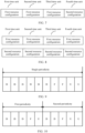
- FIG. 11 is a schematic diagram of a possible first resource configuration according to an embodiment of this application. As shown in FIG. 11 , four patterns are introduced in the first resource configuration based on the TDD resource configuration received by the terminal device in FIG. 10 .
- the first resource configuration has four patterns: a first pattern, a second pattern, a third pattern, and a fourth pattern respectively.
- a periodicity corresponding to the first pattern is referred to as a first periodicity
- a periodicity corresponding to the second pattern is referred to as a second periodicity
- a periodicity corresponding to the third pattern is referred to as a third periodicity
- a periodicity corresponding to the fourth pattern is referred to as a fourth periodicity.
- the first three slots are downlink slots, the last slot is an uplink slot, and the fourth slot is a flexible slot.
- the first two slots are downlink slots, the last two slots are uplink slots, and the third slot is a flexible slot.
- the first three slots are downlink slots, and the last two slots are uplink slots.
- the fourth periodicity the first two slots are downlink slots, and the last three slots are uplink slots.
- the first resource configuration in FIG. 11 is introduced based on the TDD resource configuration received by the terminal device in FIG. 10 . Therefore, to implement that the first resource configuration matches the TDD resource configuration received by the terminal device, a resource configuration in the first periodicity of the first resource configuration matches that in the first periodicity of the TDD resource configuration of the terminal device in FIG. 10 , and a resource configuration of the second periodicity in the first resource configuration matches that in the second periodicity of the TDD resource configuration of the terminal device in FIG. 10 .
- a resource configuration in the third periodicity of the first resource configuration matches the resource configuration in the first periodicity
- a resource configuration in the fourth periodicity of the first resource configuration matches the resource configuration in the second periodicity
- a flexible slot may be modified to an uplink slot or a downlink slot. Therefore, in FIG. 11 , the resource configuration in the third periodicity of the first resource configuration matches the resource configuration in the first periodicity of the first resource configuration, and the resource configuration in the fourth periodicity of the first resource configuration matches the resource configuration in the second periodicity of the first resource configuration.
- the second resource configuration may be directly sent by an upper-level node or a donor node, or the DU of the first node may generate the second resource configuration based on the first resource configuration.
- the second resource configuration may be configured in the foregoing single-pattern manner, or may be configured in a multi-pattern (for example, more than or equal to two patterns) manner. The following describes in detail a specific implementation process in which the DU of the first node generates the second resource configuration.
- the DU of the first node may modify the resource type in the first resource configuration based on the first resource configuration and resource type modification indication information that is sent by the upper-level node or the donor node, to obtain the second resource configuration.
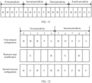
- FIG. 12 With reference to FIG. 12 , the following describes in detail, by using the first resource configuration shown in FIG. 10 as an example, a specific implementation process in which the DU of the first node generates the second resource configuration based on the first resource configuration. It should be noted that the example in FIG. 12 is merely intended to help a person skilled in the art understand the embodiments of this application, instead of limiting the embodiments of this application to a specific value or a specific scenario shown in the example.
- a slot/symbol that needs to be modified is indicated by using an index in a periodicity.
- two periodicities of the first resource configuration each include five slots, and slots that need to be modified may be indicated by using slot numbers ranging from 0 to 9.
- the first resource configuration and the second configuration periodicity may specifically have a same pattern quantity and periodicity.
- the resource type modification indication information is used to indicate to: modify a type of a slot 1 in the first resource configuration to an uplink (uplink, U) slot, modify a type of a slot 4 in the first resource configuration to a downlink (downlink, D) slot, modify a type of a slot 6 to an uplink slot, and modify a type of a slot 8 to a downlink slot.
- the DU of the first node may modify the first resource configuration based on the first resource configuration and the resource type modification indication information, to obtain the second resource configuration shown in FIG. 12 .
- a pattern length of the second resource configuration may be further increased by extending a slot index.
- more pattern quantities may be introduced into the second resource configuration, thereby increasing flexibility of the second resource configuration.
- a quantity of slots included in the first resource configuration is K, and a possible value of the slot index ranges from 0 to (K-1).
- a value range of the slot index may be increased by H times, so that a value of the slot index ranges from 0 to (HK-1), and a quantity of slots included in a modified first resource configuration is increased by H times.
- the second resource configuration is generated based on the modified first resource configuration, and the pattern length of the second resource configuration may be increased.
- FIG. 13 With reference to FIG. 13 , the following describes in detail, by using the first resource configuration shown in FIG. 12 as an example, a specific implementation process of generating the second resource configuration based on the first resource configuration whose quantity of slots is increased. It should be noted that the example in FIG. 13 is merely intended to help a person skilled in the art understand the embodiments of this application, instead of limiting the embodiments of this application to a specific value or a specific scenario shown in the example.
- the resource type modification indication information is used to indicate to: modify a type of a slot 1 in the first resource configuration to an uplink (uplink, U) slot, modify a type of a slot 4 in the first resource configuration to a downlink (downlink, D) slot, modify a type of a slot 6 to an uplink slot, modify a type of a slot 8 to a downlink slot, modify a type of a slot 15 to an uplink slot, modify a type of a slot 16 to an uplink slot, modify a type of a slot 18 to a downlink slot, and modify a type of a slot 19 to a downlink slot.
- the foregoing describes a configuration of an available resource in the second resource configuration, for example, an uplink resource, a downlink resource, and a flexible resource.
- the following describes in detail a method for configuring an unavailable resource in the second resource configuration with reference to FIG. 14 and FIG. 15 .
- the DU of the first node may modify a resource type in the second resource configuration to an unavailable resource type based on the resource type modification indication information sent by the upper-level node or the donor node, to obtain a modified second resource configuration (that is, the second resource configuration including the unavailable resource type).
- FIG. 14 the following describes in detail, by using the second resource configuration shown in FIG. 12 as an example, a specific implementation process in which the DU of the first node modifies a resource type in the second resource configuration to an unavailable resource.
- the example in FIG. 14 is merely intended to help a person skilled in the art understand the embodiments of this application, instead of limiting the embodiments of this application to a specific value or a specific scenario shown in the example.
- a slot/symbol that needs to be modified is indicated by using an index in a periodicity.
- two periodicities of the second resource configuration each include five slots, and slots that need to be modified may be indicated by using slot numbers 0 to 9.
- the resource type modification indication information is used to indicate to modify resource types of a slot 4 and a slot 6 in the second resource configuration to unavailable resources. For example, "N" in FIG. 14 indicates an unavailable resource.
- the DU of the first node may modify the second resource configuration based on the second resource configuration and the resource type modification indication information, to obtain the second resource configuration including the unavailable resources shown in FIG. 14 .
- the DU of the first node communicates with the lower-level node based on the second resource configuration including the unavailable resources, the DU of the first node cannot communicate with the lower-level node on the unavailable resources in the slot 4 and the slot 6.
- a resource type in the second resource configuration may be further modified to an unavailable resource type on the second resource configuration whose pattern length is increased, to obtain a modified second resource configuration (that is, the second resource configuration including the unavailable resource type).
- FIG. 15 the following describes in detail, by using the second resource configuration shown in FIG. 13 as an example, a specific implementation process in which the DU of the first node modifies a resource type in the second resource configuration to an unavailable resource.
- the example in FIG. 15 is merely intended to help a person skilled in the art understand the embodiments of this application, instead of limiting the embodiments of this application to a specific value or a specific scenario shown in the example.
- a slot/symbol that needs to be modified is indicated by using an index in a periodicity.
- the first resource configuration includes four pattern periodicities, and a value range of the slot index of the four pattern periodicities is modified to 0 to 19.
- the second resource configuration includes four pattern periodicities, and a value range of the slot index of the four pattern periodicities is 0 to 19.
- the resource type modification indication information is used to indicate to modify resource types of a slot 4, a slot 6, a slot 16, and a slot 17 in the second resource configuration to unavailable resources.
- "N" indicates an unavailable resource in FIG. 15 .
- the DU of the first node may modify the second resource configuration based on the second resource configuration and the resource type modification indication information, to obtain the second resource configuration including the unavailable resources shown in FIG. 15 .
- the DU of the first node communicates with the lower-level node based on the second resource configuration including the unavailable resources, the DU of the first node cannot communicate with the lower-level node on the unavailable resources in the slot 4, the slot 6, the slot 16, and the slot 17.
- a configuration of the unavailable resource may be separately for the first resource configuration and the second resource configuration, or is applicable to both the first resource configuration and the second resource configuration. This is not specifically limited in this embodiment of this application.
- the first resource configuration and the second resource configuration include only a configuration of a DU resource type (for example, D/U/F), and therefore may also be referred to as a first resource type configuration and a second resource type configuration.
- An attribute corresponding to the DU resource type may be configured through additional resource attribute (attribute).
- a resource attribute in this embodiment of this application may include but is not limited to hard, soft, and unavailable (not applicable, NA).
- the attribute corresponding to the DU resource type may be configured for each type of resource in one time domain resource.
- the donor node may configure a different resource attribute for each type of resource in one time domain resource (for example, one slot). For example, assuming that one slot includes X downlink symbols, Y flexible symbols, and Z uplink symbols, the donor may independently configure corresponding resource attributes for the downlink, flexible, and uplink symbols. For example, a resource attribute configured for the downlink symbol is hard, a resource attribute configured for the flexible symbol is soft, and a resource attribute configured for the uplink symbol is unavailable.
- a resource attribute configuration corresponding to the DU resource type in the IAB node also has a configuration periodicity.
- a resource attribute configuration periodicity is M times a resource type configuration periodicity, and M is an integer greater than or equal to 1.
- the donor may indicate, in configuration signaling, an extension multiple of the resource attribute configuration periodicity relative to the resource type configuration periodicity, that is, indicate a value of M or a value of m.
- a protocol specifies that the DU of the IAB node does not expect to receive a configuration that does not have the foregoing periodic relationship, or the IAB node considers, as an incorrect configuration, a configuration that does not have the foregoing periodic relationship.
- Resource attributes are configured by resource type.
- a resource attribute of a symbol is determined based on the following conditions: an attribute configuration of a slot of the symbol and a resource type of the symbol. For example, one slot may have the following attribute configuration: ⁇ uplink symbol attribute, downlink symbol attribute, flexible symbol attribute ⁇ .
- a symbol When a DU cell of the IAB has a first resource type configuration and a second resource type configuration, a symbol may be indicated as different resource types by the first resource type configuration and the second resource type configuration, and in this case, the symbol may not have a unique attribute. Because the upper-level node performs conflict avoidance based on an attribute of a DU resource of the IAB node, a non-unique attribute of the DU resource on the IAB may cause a conflict between an MT resource and the DU resource.
- one method is to associate a resource attribute configuration with a specific resource configuration.
- the resource attribute configuration is associated with the first resource (type) configuration.
- the donor node indicates, by using signaling, a resource (type) configuration associated with the resource attribute configuration.
- the IAB node and the upper-level node determine an attribute of the DU resource of the IAB node based on the resource attribute configuration and the associated resource type configuration, and may perform conflict avoidance of backhaul link transmission based on the resource attribute configuration and the associated resource type configuration. Therefore, both the IAB node and the upper-level node of the IAB node need to learn of the resource type configuration associated with the resource attribute configuration.
- the donor node may provide, for only the upper-level node of the IAB node, the resource type configuration that is associated with the resource attribute configuration and that is of the DU (each cell) of the IAB node, instead of all resource type configurations of the DU (each cell) of the IAB node.
- the resource attribute configuration of the IAB node is associated with a plurality of resource type configurations.
- the IAB node and the upper-level node perform conflict avoidance of backhaul link transmission based on the resource attribute configuration and the plurality of associated resource configurations.
- the resource attribute configuration is associated with the plurality of resource type configurations
- a resource type of each symbol is a combination of the plurality of resource type configurations
- the resource attribute configuration is associated with the combined resource type configurations.
- the donor node provides a plurality of resource attribute configurations for the IAB node, and the plurality of resource attribute configurations are respectively associated with a plurality of resource configurations.
- the donor node provides a first resource attribute configuration and a second resource attribute configuration for the IAB node, and the first resource attribute configuration and the second resource attribute configuration are respectively associated with the first resource type configuration and the second resource type configuration.
- the upper-level node needs to learn of an association relationship between the resource attribute configuration and the resource type configuration of the IAB node.
- the association relationship may be provided by the donor node for the upper-level node, or may be reported by the IAB node to the upper-level node.
- the upper-level node As described above, availability of a soft resource of the DU of the IAB node needs to be indicated by the upper-level node, and the upper-level node also indicates the availability of the soft resource by slot by resource type. Specifically, the upper-level node may indicate one or more of the following eight available states for one slot of the DU of the IAB node: Value Meaning 0 All resources are unavailable 1 A downlink resource is available 2 An uplink resource is available 3 Downlink and uplink resources are available 4 A flexible resource is available 5 Downlink and flexible resources are available 6 Uplink and flexible resources are available 7 All resources are available
- an indication for the availability of the soft resource of the DU of the IAB node performed by the upper-level node also needs to be associated with a resource type configuration of the IAB node.
- the indication for the availability of the soft resource of the DU of the IAB node is associated with the first resource type configuration.
- An association relationship between a dynamic indication and a resource configuration may be defined by a protocol.
- the dynamic indication is associated with the first resource type configuration, or may be configured by the donor node, or may be configured by the upper-level node.
- that the dynamic indication is associated with the resource configuration means that the IAB node determines availability of an indicated slot resource based on dynamic indication content and the associated resource configuration.
- the dynamic indication is associated with one DU resource configuration means that the IAB node and the upper-level node determine a backhaul link resource by using the dynamic indication and the associated resource configuration, and does not mean that the DU of the IAB node cannot communicate with the lower-level node by using an unassociated resource configuration.
- the dynamic indication and the resource attribute configuration are associated with a same resource type configuration.
- a resource conflict avoidance principle is as follows: Receiving and sending of the MT of the IAB node on the backhaul link should not affect receiving and sending of available resources of each cell of the DU of the IAB node.
- the available resources of each cell of the DU of the IAB node are a hard resource indicated by the resource attribute configuration and a soft resource indicated as being available by dynamic signaling.
- the IAB node and the upper-level node of the IAB node determine an available resource of the MT of the IAB node based on the resource attribute configuration, the dynamic signaling, and a resource configuration associated with the resource attribute configuration and the dynamic signaling. If the DU of the IAB node needs to use an unassociated resource type configuration for transmission, the available resource of the MT determined in the foregoing process should not be affected.
- the dynamic signaling indicates only one resource attribute configuration and an associated resource type configuration.
- the upper-level node configures the resource attribute configuration indicated by the dynamic signaling.
- the DU of the first node may further generate a child node resource configuration based on the first resource configuration and/or the second resource configuration, and send the child node resource configuration to a child node.
- the child node resource configuration sent by the DU of the first node does not necessarily need to entirely match the first resource configuration and/or the second resource configuration of the first node.
- the time domain resource in the child node resource configuration generated by the DU of the first node may be set to any one of D, U, or F.
- different child nodes may have different configurations.
- the time domain resource in the child node resource configuration generated by the DU of the first node may be set to any one of D(U) or F.
- the child node resource configuration may be generated by a parent node or a donor node of the first node, that is, the parent node or the donor node of the first node may separately generate the DU resource configuration (for example, the first resource configuration and/or the second resource configuration) of the first node and the child node resource configuration.
- the DU resource configuration of the first node and the child node resource configuration that are generated by the parent node or the donor node of the first node should match each other, that is, the DU of the first node does not expect to receive the DU resource configuration and the child node resource configuration that conflict.
- the conflicting resource configuration means that the DU resource configuration is reverse to the child node resource configuration, that is, one is set to D, and the other is set to U.
- steps implemented by the first node may also be implemented by a component (for example, a chip or a circuit) that can be used in the first node.
- FIG. 16 is a schematic block diagram of a resource configuration apparatus 1600 according to an embodiment of this application. It may be understood that the communication apparatus 1600 may be a first node, or may be a component that can be used in the first node.
- the resource configuration apparatus 1600 includes:
- the foregoing resource configuration apparatus may obtain at least two DU resource configurations, and different DU resource configurations correspond to different users. Different user types are distinguished by using different resource configurations, so that the DU of the first node uses appropriate resource configurations when communicating with different users. In addition to supporting a function of multiplexing a plurality of resources, compatibility with existing UE may further be ensured.
- the communication module 1620 is specifically configured to perform one or more of the following: communicating with the terminal device in a first time unit based on the first resource configuration; communicating with the terminal device and/or the second node in the first time unit based on the first resource configuration; and communicating with the second node in the first time unit based on the second resource configuration.
- a correspondence between the first time unit and the first resource configuration or the second resource configuration is preconfigured in advance.
- the obtaining module 1610 is specifically configured to receive the at least one second resource configuration sent by a third node, where the third node is a parent node or a donor node of the first node.
- the obtaining module 1610 is specifically configured to receive first indication information from a third node, where the first indication information is used to indicate the DU side of the first node to modify a resource type in the first resource configuration.
- the obtaining module 1610 is specifically configured to: modify an uplink resource type in the first resource configuration to a downlink resource type or a flexible resource type based on the first indication information; modify a downlink resource type in the first resource configuration to an uplink resource type or a flexible resource type; or modify a flexible resource type in the first resource configuration to an uplink resource type or a downlink resource type.
- the first indication information is further used to indicate to extend a configuration periodicity of the first resource configuration.
- the obtaining module 1610 is specifically configured to: extend the configuration periodicity of the first resource configuration based on the first indication information; and modify a resource type in an extended first resource configuration.
- the obtaining module 1610 is specifically configured to receive second indication information from the third node, where the second indication information is used to indicate the DU side of the first node to modify a resource type in a received original first resource configuration to an unavailable resource.
- the obtaining module 1610 is specifically configured to receive third indication information from the third node, where the third indication information is used to indicate the DU side of the first node to modify a resource type in at least one received original second resource configuration to an unavailable resource.
- the second indication information is further used to indicate to extend a configuration periodicity of the received original first resource configuration
- the third indication information is further used to indicate to extend a configuration periodicity of the received original second resource configuration.
- the apparatus 1600 further includes: a sending module 1630, configured to send a child node resource configuration to the terminal device and/or the second node, where the child node configuration is generated by the DU side of the first node based on the first resource configuration and/or the second resource configuration.
- a sending module 1630 configured to send a child node resource configuration to the terminal device and/or the second node, where the child node configuration is generated by the DU side of the first node based on the first resource configuration and/or the second resource configuration.
- the communication module 1620 is specifically configured to: select, based on a user in a first user group, the first resource configuration to communicate with the user in the first user group, where the first user group includes the terminal device and/or the second node; or select, based on a user in a first user group, the second resource configuration to communicate with the user in the first user group, where the second user group includes only the second node.
- the DU side of the first node includes N cells
- the second resource configuration is configured for M cells
- M is a positive integer less than or equal to N.
- FIG. 17 is a schematic block diagram of a resource configuration apparatus 1700 according to an embodiment of this application.
- the resource configuration apparatus 1700 may include a processor 1701 and a memory 1703.
- the processor 1701 may be connected to the memory 1703.
- the memory 1703 may be configured to store program code and data of the resource configuration apparatus 1700. Therefore, the memory 1703 may be a storage unit in the processor 1701, an external storage unit independent of the processor 1701, or a component including a storage unit in the processor 1701 and an external storage unit independent of the processor 1701.
- the resource configuration apparatus 1700 may further include a bus 1704.
- the memory 1703 may be connected to the processor 1701 by using the bus 1704.
- the bus 1704 may be a peripheral component interconnect (peripheral component interconnect, PCI) bus, an extended industry standard architecture (extended industry standard architecture, EISA) bus, or the like.
- PCI peripheral component interconnect
- EISA extended industry standard architecture
- the bus 1704 may be classified into an address bus, a data bus, a control bus, and the like. For ease of representation, only one thick line is used to represent the bus in FIG. 17 , but this does not mean that there is only one bus or only one type of bus.
- the processor 1701 may include but is not limited to at least one of the following computing devices that run various types of software: a central processing unit (central processing unit, CPU), a microprocessor, a digital signal processor (digital signal processor, DSP), a microcontroller unit (microcontroller unit, MCU), an artificial intelligence processor, or the like.
- Each computing device may include one or more cores configured to perform an operation or processing by executing software instructions.
- the processor may be an independent semiconductor chip, or may be integrated with another circuit to constitute a semiconductor chip.
- the processor may constitute a system on chip with another circuit (for example, an encoding/decoding circuit, a hardware acceleration circuit, or various bus and interface circuits).
- the processor may be integrated into an application specific integrated circuit (application specific integrated circuit, ASIC) as a built-in processor of the ASIC, and the ASIC integrated with the processor may be independently packaged or may be packaged with another circuit.
- ASIC application specific integrated circuit
- the processor includes a core configured to perform an operation or processing by executing software instructions, and may further include a necessary hardware accelerator, for example, a field programmable gate array (field programmable gate array, FPGA), a programmable logic device (programmable logic device, PLD), or a logic circuit that implements a dedicated logic operation.
- FPGA field programmable gate array
- PLD programmable logic device
- the processor 1701 When executing a program, the processor 1701 is configured to: obtain, by a distributed unit DU side of a first node, a first resource configuration and at least one second resource configuration, where the first resource configuration is used to indicate a DU side of a first node to communicate with a terminal device and/or a second node by using the first resource configuration, the second resource configuration is used to indicate the DU side of the first node to communicate with the second node by using the second resource configuration, the first node is a relay node, and the second node is a child node of the first node; and communicate, by the DU side of the first node, with the terminal device and/or the second node.
- the DU of the first node may obtain at least two DU resource configurations, and different DU resource configurations correspond to different users. Different user types are distinguished by using different resource configurations, so that the DU of the first node uses appropriate resource configurations when communicating with different users. In addition to supporting a function of multiplexing a plurality of resources, compatibility with existing UE may further be ensured.
- the DU side of the first node communicates with the terminal device and/or the second node includes one or more of the following: the DU side of the first node communicates with the terminal device in a first time unit based on the first resource configuration; the DU side of the first node communicates with the terminal device and/or the second node in the first time unit based on the first resource configuration; and the DU side of the first node communicates with the second node in the first time unit based on the second resource configuration.
- a correspondence between the first time unit and the first resource configuration or the second resource configuration is preconfigured in advance.
- the DU side of the first node receives the first resource configuration sent by the third node.
- the DU side of the first node receives first indication information from a third node, where the first indication information is used to indicate the DU side of the first node to modify a resource type in the first resource configuration.
- the first indication information is further used to indicate to extend a configuration periodicity of the first resource configuration.
- the DU side of the first node extends the configuration periodicity of the first resource configuration based on the first indication information, and the DU side of the first node modifies a resource type in an extended first resource configuration.
- the DU side of the first node receives second indication information from the third node, where the second indication information is used to indicate the DU side of the first node to modify a resource type in a received original first resource configuration to an unavailable resource.
- the DU side of the first node receives third indication information from the third node, where the third indication information is used to indicate the DU side of the first node to modify a resource type in at least one received original second resource configuration to an unavailable resource.
- the second indication information is further used to indicate to extend a configuration periodicity of the received original first resource configuration
- the third indication information is further used to indicate to extend a configuration periodicity of the received original second resource configuration.
- the method further includes: The DU side of the first node sends a child node resource configuration to the terminal device and/or the second node, where the child node configuration is generated by the DU side of the first node based on the first resource configuration and/or the second resource configuration.
- the DU side of the first node selects, based on a user in a first user group, the first resource configuration to communicate with the user in the first user group, where the first user group includes the terminal device and/or the second node.
- the DU side of the first node selects, based on a user in a first user group, the second resource configuration to communicate with the user in the first user group, where the second user group includes only the second node.
- the DU side of the first node includes N cells
- the second resource configuration is configured for M cells
- M is a positive integer less than or equal to N.
- module in this embodiment of this application may also be referred to as a unit, a circuit, or the like. This is not limited in this embodiment of this application.
- the resource configuration apparatus may perform some or all of the steps in the foregoing embodiments. These steps or operations are merely examples. In this embodiment of this application, other operations or variations of various operations may be further performed. In addition, the steps may be performed in a sequence different from that presented in the foregoing embodiments, and not all the operations in the foregoing embodiments are necessarily performed.
- An embodiment of this application further provides a computer-readable medium, configured to store a computer program.
- the computer program includes instructions used to perform the method in any possible implementation of any one of the foregoing aspects.
- An embodiment of this application further provides a computer program product, used in a resource configuration apparatus.
- the computer program product includes computer program code.
- the computer program code When the computer program code is run on a computer, the computer is enabled to perform the method in any possible implementation of any one of the foregoing aspects.
- An embodiment of this application further provides a chip system, used in a resource configuration apparatus.
- the chip system includes: at least one processor, at least one memory, and an interface circuit.
- the interface circuit is responsible for information exchange between the chip system and an external environment.
- the at least one memory, the interface circuit, and the at least one processor are connected to each other by using a line.
- the at least one memory stores instructions. The instructions are executed by the at least one processor to perform operations in the methods in the foregoing aspects.
- the at least one memory is optional.
- aspects or features in the embodiments of this application may be implemented as a method, an apparatus, or a product that uses standard programming and/or engineering technologies.
- product used in this application covers a computer program that can be accessed from any computer-readable component, carrier, or medium.
- the computer-readable medium may include but is not limited to: a magnetic storage component (for example, a hard disk, a floppy disk, or a magnetic tape), an optical disc (for example, a compact disc (compact disc, CD) or a digital versatile disc (digital versatile disc, DVD)), a smart card, and a flash memory component (for example, an erasable programmable read-only memory (erasable programmable read-only memory, EPROM), a card, a stick, or a key drive).
- various storage media described in this specification may represent one or more devices and/or other machine-readable media that are configured to store information.
- the term "machine-readable media" may include but is not limited to radio channels and various other media that can store, include, and/or carry instructions and/or data.
- system and “network” may be used interchangeably in this specification.
- the term “and/or” in this specification describes only an association relationship between associated objects and represents that there may be three relationships. For example, A and/or B may represent the following three cases: Only A exists, both A and B exist, and only B exists.
- the character “/" in this specification usually indicates an "or" relationship between the associated objects.
- B corresponding to A indicates that B is associated with A, and B may be determined according to A.
- determining A according to B does not mean that B is determined according to A only; that is, B may also be determined according to A and/or other information.
- All or some of the foregoing embodiments may be implemented by using software, hardware, firmware, or any combination thereof.
- software is used to implement the embodiments, all or some of the embodiments may be implemented in a form of a computer program product.
- the computer program product includes one or more computer instructions.
- the computer may be a general-purpose computer, a dedicated computer, a computer network, or another programmable apparatus.
- the computer instructions may be stored in a computer-readable storage medium or may be transmitted from a computer-readable storage medium to another computer-readable storage medium.
- the computer instructions may be transmitted from a website, computer, server, or data center to another website, computer, server, or data center in a wired (for example, a coaxial cable, an optical fiber, or a digital subscriber line (digital subscriber line, DSL)) or wireless (for example, infrared, radio, or microwave) manner.
- the computer-readable storage medium may be any usable medium accessible by a computer, or a data storage device, such as a server or a data center, including one or more usable media that are integrated.
- the usable medium may be a magnetic medium (for example, a floppy disk, a hard disk, or a magnetic tape), an optical medium (for example, a digital video disc (digital video disc, DVD)), a semiconductor medium (for example, a solid-state drive (solid state disk, SSD)), or the like.
- a magnetic medium for example, a floppy disk, a hard disk, or a magnetic tape
- an optical medium for example, a digital video disc (digital video disc, DVD)
- a semiconductor medium for example, a solid-state drive (solid state disk, SSD)
- the units described as separate parts may or may not be physically separate, and parts displayed as units may or may not be physical units, may be located in one position, or may be distributed on a plurality of network units. Some or all of the units may be selected based on an actual requirement to achieve the objectives of the solutions in this embodiment.
- the functions When the functions are implemented in a form of a software functional unit and sold or used as an independent product, the functions may be stored in a computer-readable storage medium. Based on such an understanding, the technical solutions of this application essentially, or the part contributing to the conventional technology, or some of the technical solutions may be implemented in a form of a software product.
- the computer software product is stored in a storage medium, and includes several instructions for instructing a computer device (which may be a personal computer, a server, a network device, or the like) to perform all or some of the steps of the methods described in the embodiments of this application.
- the storage medium includes any medium that can store program code, such as a USB flash drive, a removable hard disk, a read-only memory (read-only memory, ROM), a random access memory (random access memory, RAM), a magnetic disk, or an optical disc.
- program code such as a USB flash drive, a removable hard disk, a read-only memory (read-only memory, ROM), a random access memory (random access memory, RAM), a magnetic disk, or an optical disc.
Landscapes
- Engineering & Computer Science (AREA)
- Signal Processing (AREA)
- Computer Networks & Wireless Communication (AREA)
- Mobile Radio Communication Systems (AREA)
Claims (6)
- Ressourcenkonfigurationsverfahren, das durch eine Seite einer verteilten Einheit, DU, DU-Seite, eines ersten Knotens durchgeführt wird, wobei das Verfahren die folgenden Schritte umfasst:• Erlangen (Schritt 510) einer ersten Ressourcenkonfiguration und einer zweiten Ressourcenkonfiguration, wobei die erste Ressourcenkonfiguration verwendet wird, um der DU-Seite des ersten Knotens anzugeben, mit einer Endgeräteeinrichtung und/oder einem zweiten Knoten unter Verwendung der ersten Ressourcenkonfiguration zu kommunizieren, die zweite Ressourcenkonfiguration verwendet wird, um der DU-Seite des ersten Knotens anzugeben, mit dem zweiten Knoten unter Verwendung der zweiten Ressourcenkonfiguration zu kommunizieren, es sich bei dem ersten Knoten um einen Relaisknoten handelt und es sich bei dem zweite Knoten um einen untergeordneten Knoten des ersten Knotens handelt,wobei das Erlangen der zweiten Ressourcenkonfiguration Folgendes umfasst:o Empfangen erster Angabeinformationen von einem dritten Knoten, wobei der dritte Knoten ein übergeordneter Knoten oder ein Geberknoten des ersten Knotens ist, wobei die ersten Angabeinformationen zu Folgendem verwendet werden:▪ Angeben der DU-Seite des ersten Knotens, um einen Ressourcentyp der ersten Ressourcenkonfiguration zu modifizieren, und Angeben der DU-Seite des ersten Knotens, in welchen Ressourcentyp der Ressourcentyp der ersten Ressourcenkonfiguration zu modifizieren ist, und▪ Angeben, dass eine Konfigurationsperiodizität der ersten Ressourcenkonfiguration zu erweitern ist und wie diese zu erweitern ist;o Erweitern der Konfigurationsperiodizität der ersten Ressourcenkonfiguration basierend auf den ersten Angabeinformationen, um eine erweiterte erste Ressourcenkonfiguration zu erreichen, undo Modifizieren eines Ressourcentyps in der erweiterten ersten Ressourcenkonfiguration basierend auf den ersten Angabeinformationen, wodurch die zweite Ressourcenkonfiguration erreicht wird; und• Kommunizieren (Schritt 520) mit der Endgeräteeinrichtung und dem zweiten Knoten, wobei das Kommunizieren mit der Endgeräteeinrichtung und dem zweiten Knoten Folgendes umfasst:o Kommunizieren mit der Endgeräteeinrichtung in einer ersten Zeiteinheit basierend auf der ersten Ressourcenkonfiguration undo Kommunizieren mit dem zweiten Knoten in der ersten Zeiteinheit basierend auf der zweiten Ressourcenkonfiguration.
- Verfahren nach Anspruch 1, wobei das Modifizieren des Ressourcentyps in der erweiterten ersten Ressourcenkonfiguration basierend auf den ersten Angabeinformationen Folgendes umfasst:o Modifizieren eines Uplink-Ressourcentyps in der erweiterten ersten Ressourcenkonfiguration in einen Downlink-Ressourcentyp oder einen flexiblen Ressourcentyp basierend auf den ersten Angabeinformationen;o Modifizieren eines Downlink-Ressourcentyps in der erweiterten ersten Ressourcenkonfiguration in einen Uplink-Ressourcentyp oder einen flexiblen Ressourcentyp basierend auf den ersten Angabeinformationen; odero Modifizieren eines flexiblen Ressourcentyps in der erweiterten ersten Ressourcenkonfiguration in einen Uplink-Ressourcentyp oder einen Downlink-Ressourcentyp basierend auf den ersten Angabeinformationen.
- Verfahren nach einem der Ansprüche 1 bis 2, wobei das Erlangen der ersten Ressourcenkonfiguration Folgendes umfasst:o Empfangen zweiter Angabeinformationen von dem dritten Knoten, wobei die zweiten Angabeinformationen verwendet werden, um der DU-Seite des ersten Knotens anzugeben, einen Ressourcentyp in einer empfangenen ursprünglichen ersten Ressourcenkonfiguration in eine nicht verfügbare Ressource zu modifizieren.
- Verfahren nach einem der Ansprüche 1 bis 3, wobei das Verfahren ferner Folgendes umfasst:o Senden einer Ressourcenkonfiguration eines untergeordneten Knotens an die Endgeräteeinrichtung und/oder den zweiten Knoten, wobei die Konfiguration des untergeordneten Knotens durch die DU-Seite des ersten Knotens basierend auf der ersten Ressourcenkonfiguration und/oder der zweiten Ressourcenkonfiguration erzeugt wird.
- Verfahren nach einem der Ansprüche 1 bis 4, wobei das Kommunizieren mit der Endgeräteeinrichtung und/oder dem zweiten Knoten Folgendes umfasst:o Auswählen, basierend auf einem Benutzer in einer ersten Benutzergruppe, der ersten Ressourcenkonfiguration, um mit dem Benutzer in der ersten Benutzergruppe zu kommunizieren, wobei die erste Benutzergruppe die Endgeräteeinrichtung und/oder den zweiten Knoten umfasst; odero Auswählen, basierend auf dem Benutzer in der ersten Benutzergruppe, der zweiten Ressourcenkonfiguration, um mit dem Benutzer in der ersten Benutzergruppe zu kommunizieren, wobei die zweite Benutzergruppe nur den zweiten Knoten umfasst.
- Seite einer verteilten Einheit, DU, DU-Seite, eines ersten Knotens, wobei die DU-Seite des ersten Knotens dazu konfiguriert ist, eines der Verfahren nach den Ansprüchen 1 bis 5 durchzuführen.
Applications Claiming Priority (3)
| Application Number | Priority Date | Filing Date | Title |
|---|---|---|---|
| CN201910726198 | 2019-08-07 | ||
| CN201911089500.6A CN112350811A (zh) | 2019-08-07 | 2019-11-08 | 资源配置的方法以及装置 |
| PCT/CN2020/104293 WO2021023023A1 (zh) | 2019-08-07 | 2020-07-24 | 资源配置的方法以及装置 |
Publications (3)
| Publication Number | Publication Date |
|---|---|
| EP4007202A1 EP4007202A1 (de) | 2022-06-01 |
| EP4007202A4 EP4007202A4 (de) | 2022-09-28 |
| EP4007202B1 true EP4007202B1 (de) | 2025-01-01 |
Family
ID=74367877
Family Applications (1)
| Application Number | Title | Priority Date | Filing Date |
|---|---|---|---|
| EP20850106.4A Active EP4007202B1 (de) | 2019-08-07 | 2020-07-24 | Ressourcenkonfigurationsverfahren und -vorrichtung |
Country Status (4)
| Country | Link |
|---|---|
| US (1) | US12185317B2 (de) |
| EP (1) | EP4007202B1 (de) |
| CN (1) | CN112350811A (de) |
| WO (1) | WO2021023023A1 (de) |
Families Citing this family (1)
| Publication number | Priority date | Publication date | Assignee | Title |
|---|---|---|---|---|
| US12323954B2 (en) * | 2020-03-16 | 2025-06-03 | Lg Electronics Inc. | Method and device for operation of IAB node in situation in which multiple parent nodes are connected to single IAB node |
Family Cites Families (8)
| Publication number | Priority date | Publication date | Assignee | Title |
|---|---|---|---|---|
| CN104363597A (zh) * | 2010-08-24 | 2015-02-18 | 华为技术有限公司 | 频谱资源的配置调整方法和装置及系统 |
| US20180035435A1 (en) * | 2016-07-27 | 2018-02-01 | Qualcomm Incorporated | Mechanisms for interference management of multi-tti sidelink-centric subframes in wireless communication |
| CN108365936B (zh) * | 2017-01-26 | 2020-10-27 | 华为技术有限公司 | 一种通信方法,装置及系统 |
| CN108111281B (zh) * | 2017-09-12 | 2022-03-01 | 中兴通讯股份有限公司 | 数据信道参数配置方法及装置 |
| CN111819900A (zh) * | 2018-01-12 | 2020-10-23 | 瑞典爱立信有限公司 | 时分双工通信中的所配置的授权 |
| CN110972266B (zh) * | 2018-09-28 | 2022-12-30 | 成都华为技术有限公司 | 配置时隙格式的方法和通信装置 |
| CN111436145A (zh) * | 2019-01-11 | 2020-07-21 | 华为技术有限公司 | 资源配置的方法和装置 |
| CN111867067B (zh) * | 2019-04-30 | 2023-07-21 | 中国移动通信有限公司研究院 | 一种随机接入资源关联方法及节点 |
-
2019
- 2019-11-08 CN CN201911089500.6A patent/CN112350811A/zh active Pending
-
2020
- 2020-07-24 EP EP20850106.4A patent/EP4007202B1/de active Active
- 2020-07-24 WO PCT/CN2020/104293 patent/WO2021023023A1/zh not_active Ceased
-
2022
- 2022-02-07 US US17/665,966 patent/US12185317B2/en active Active
Also Published As
| Publication number | Publication date |
|---|---|
| EP4007202A1 (de) | 2022-06-01 |
| US12185317B2 (en) | 2024-12-31 |
| WO2021023023A1 (zh) | 2021-02-11 |
| US20220159642A1 (en) | 2022-05-19 |
| EP4007202A4 (de) | 2022-09-28 |
| CN112350811A (zh) | 2021-02-09 |
Similar Documents
| Publication | Publication Date | Title |
|---|---|---|
| JP7645309B2 (ja) | リソース構成方法および装置 | |
| JP7055869B2 (ja) | マルチキャリア通信のためのキャリア・スイッチング方法、装置およびシステム | |
| US12232125B2 (en) | Communication method and communications apparatus | |
| US20240214994A1 (en) | Signal transmission method and communication apparatus | |
| JP2020534740A (ja) | 同期信号ブロックと制御リソースセットとの多重化 | |
| EP4044707A1 (de) | Dynamische ressourcenanzeigeverfahren und -vorrichtung | |
| JP2021503845A (ja) | 通信方法および通信デバイス | |
| CN114765834A (zh) | 非激活态下数据传输方法及装置 | |
| EP3609263B1 (de) | Kommunikationsverfahren und kommunikationsvorrichtung | |
| KR20170127443A (ko) | 밀리미터파 네트워크들에서의 무선 백홀과 액세스 통신들 사이의 리소스 파티셔닝 | |
| US12464420B2 (en) | Communication method and communication apparatus | |
| JP2019527977A (ja) | 無線アクセス技術を使用するワイヤレスネットワークにおけるシグナリングおよびリソース割振りの協調 | |
| EP4199573A1 (de) | Kommunikationsverfahren und -vorrichtung | |
| CN117750456B (zh) | 小区切换方法、设备、存储介质、芯片系统及产品 | |
| US20240334356A1 (en) | Communication method and apparatus | |
| EP4184991A1 (de) | Kommunikationsverfahren und -vorrichtung | |
| WO2021064975A1 (ja) | ユーザ装置及び通信方法 | |
| US12185317B2 (en) | Resource configuration method and apparatus | |
| CN117652172A (zh) | 用于去激活的PSCell的载波特定缩放因子 | |
| EP4185050A1 (de) | Kommunikationsverfahren und -vorrichtung | |
| WO2023216929A1 (zh) | 一种通信的方法和装置 | |
| CN119096580A (zh) | 无线通信方法、用户设备和网络设备 | |
| EP4017162A1 (de) | Ressourcenanzeigeverfahren und -vorrichtung | |
| WO2021032014A1 (zh) | 一种小区配置的确定方法及装置 | |
| US12598595B2 (en) | Communication method and apparatus |
Legal Events
| Date | Code | Title | Description |
|---|---|---|---|
| STAA | Information on the status of an ep patent application or granted ep patent |
Free format text: STATUS: THE INTERNATIONAL PUBLICATION HAS BEEN MADE |
|
| PUAI | Public reference made under article 153(3) epc to a published international application that has entered the european phase |
Free format text: ORIGINAL CODE: 0009012 |
|
| STAA | Information on the status of an ep patent application or granted ep patent |
Free format text: STATUS: REQUEST FOR EXAMINATION WAS MADE |
|
| 17P | Request for examination filed |
Effective date: 20220223 |
|
| AK | Designated contracting states |
Kind code of ref document: A1 Designated state(s): AL AT BE BG CH CY CZ DE DK EE ES FI FR GB GR HR HU IE IS IT LI LT LU LV MC MK MT NL NO PL PT RO RS SE SI SK SM TR |
|
| A4 | Supplementary search report drawn up and despatched |
Effective date: 20220829 |
|
| RIC1 | Information provided on ipc code assigned before grant |
Ipc: H04B 7/155 20060101ALI20220823BHEP Ipc: H04L 5/14 20060101ALI20220823BHEP Ipc: H04L 5/00 20060101AFI20220823BHEP |
|
| DAV | Request for validation of the european patent (deleted) | ||
| DAX | Request for extension of the european patent (deleted) | ||
| GRAP | Despatch of communication of intention to grant a patent |
Free format text: ORIGINAL CODE: EPIDOSNIGR1 |
|
| STAA | Information on the status of an ep patent application or granted ep patent |
Free format text: STATUS: GRANT OF PATENT IS INTENDED |
|
| RIC1 | Information provided on ipc code assigned before grant |
Ipc: H04B 7/155 20060101ALI20240730BHEP Ipc: H04L 5/14 20060101ALI20240730BHEP Ipc: H04L 5/00 20060101AFI20240730BHEP |
|
| INTG | Intention to grant announced |
Effective date: 20240830 |
|
| GRAS | Grant fee paid |
Free format text: ORIGINAL CODE: EPIDOSNIGR3 |
|
| GRAA | (expected) grant |
Free format text: ORIGINAL CODE: 0009210 |
|
| STAA | Information on the status of an ep patent application or granted ep patent |
Free format text: STATUS: THE PATENT HAS BEEN GRANTED |
|
| AK | Designated contracting states |
Kind code of ref document: B1 Designated state(s): AL AT BE BG CH CY CZ DE DK EE ES FI FR GB GR HR HU IE IS IT LI LT LU LV MC MK MT NL NO PL PT RO RS SE SI SK SM TR |
|
| REG | Reference to a national code |
Ref country code: GB Ref legal event code: FG4D |
|
| REG | Reference to a national code |
Ref country code: DE Ref legal event code: R096 Ref document number: 602020044238 Country of ref document: DE |
|
| REG | Reference to a national code |
Ref country code: CH Ref legal event code: EP |
|
| REG | Reference to a national code |
Ref country code: IE Ref legal event code: FG4D |
|
| REG | Reference to a national code |
Ref country code: LT Ref legal event code: MG9D |
|
| REG | Reference to a national code |
Ref country code: NL Ref legal event code: MP Effective date: 20250101 |
|
| REG | Reference to a national code |
Ref country code: AT Ref legal event code: MK05 Ref document number: 1757404 Country of ref document: AT Kind code of ref document: T Effective date: 20250101 |
|
| PG25 | Lapsed in a contracting state [announced via postgrant information from national office to epo] |
Ref country code: NL Free format text: LAPSE BECAUSE OF FAILURE TO SUBMIT A TRANSLATION OF THE DESCRIPTION OR TO PAY THE FEE WITHIN THE PRESCRIBED TIME-LIMIT Effective date: 20250101 |
|
| PG25 | Lapsed in a contracting state [announced via postgrant information from national office to epo] |
Ref country code: FI Free format text: LAPSE BECAUSE OF FAILURE TO SUBMIT A TRANSLATION OF THE DESCRIPTION OR TO PAY THE FEE WITHIN THE PRESCRIBED TIME-LIMIT Effective date: 20250101 |
|
| PG25 | Lapsed in a contracting state [announced via postgrant information from national office to epo] |
Ref country code: PL Free format text: LAPSE BECAUSE OF FAILURE TO SUBMIT A TRANSLATION OF THE DESCRIPTION OR TO PAY THE FEE WITHIN THE PRESCRIBED TIME-LIMIT Effective date: 20250101 |
|
| PG25 | Lapsed in a contracting state [announced via postgrant information from national office to epo] |
Ref country code: ES Free format text: LAPSE BECAUSE OF FAILURE TO SUBMIT A TRANSLATION OF THE DESCRIPTION OR TO PAY THE FEE WITHIN THE PRESCRIBED TIME-LIMIT Effective date: 20250101 |
|
| PGFP | Annual fee paid to national office [announced via postgrant information from national office to epo] |
Ref country code: GB Payment date: 20250605 Year of fee payment: 6 |
|
| PG25 | Lapsed in a contracting state [announced via postgrant information from national office to epo] |
Ref country code: NO Free format text: LAPSE BECAUSE OF FAILURE TO SUBMIT A TRANSLATION OF THE DESCRIPTION OR TO PAY THE FEE WITHIN THE PRESCRIBED TIME-LIMIT Effective date: 20250401 Ref country code: IS Free format text: LAPSE BECAUSE OF FAILURE TO SUBMIT A TRANSLATION OF THE DESCRIPTION OR TO PAY THE FEE WITHIN THE PRESCRIBED TIME-LIMIT Effective date: 20250501 |
|
| PG25 | Lapsed in a contracting state [announced via postgrant information from national office to epo] |
Ref country code: HR Free format text: LAPSE BECAUSE OF FAILURE TO SUBMIT A TRANSLATION OF THE DESCRIPTION OR TO PAY THE FEE WITHIN THE PRESCRIBED TIME-LIMIT Effective date: 20250101 |
|
| PG25 | Lapsed in a contracting state [announced via postgrant information from national office to epo] |
Ref country code: LV Free format text: LAPSE BECAUSE OF FAILURE TO SUBMIT A TRANSLATION OF THE DESCRIPTION OR TO PAY THE FEE WITHIN THE PRESCRIBED TIME-LIMIT Effective date: 20250101 Ref country code: PT Free format text: LAPSE BECAUSE OF FAILURE TO SUBMIT A TRANSLATION OF THE DESCRIPTION OR TO PAY THE FEE WITHIN THE PRESCRIBED TIME-LIMIT Effective date: 20250502 |
|
| PGFP | Annual fee paid to national office [announced via postgrant information from national office to epo] |
Ref country code: FR Payment date: 20250610 Year of fee payment: 6 |
|
| PG25 | Lapsed in a contracting state [announced via postgrant information from national office to epo] |
Ref country code: GR Free format text: LAPSE BECAUSE OF FAILURE TO SUBMIT A TRANSLATION OF THE DESCRIPTION OR TO PAY THE FEE WITHIN THE PRESCRIBED TIME-LIMIT Effective date: 20250402 Ref country code: BG Free format text: LAPSE BECAUSE OF FAILURE TO SUBMIT A TRANSLATION OF THE DESCRIPTION OR TO PAY THE FEE WITHIN THE PRESCRIBED TIME-LIMIT Effective date: 20250101 |
|
| PG25 | Lapsed in a contracting state [announced via postgrant information from national office to epo] |
Ref country code: AT Free format text: LAPSE BECAUSE OF FAILURE TO SUBMIT A TRANSLATION OF THE DESCRIPTION OR TO PAY THE FEE WITHIN THE PRESCRIBED TIME-LIMIT Effective date: 20250101 |
|
| PG25 | Lapsed in a contracting state [announced via postgrant information from national office to epo] |
Ref country code: CZ Free format text: LAPSE BECAUSE OF FAILURE TO SUBMIT A TRANSLATION OF THE DESCRIPTION OR TO PAY THE FEE WITHIN THE PRESCRIBED TIME-LIMIT Effective date: 20250101 |
|
| PG25 | Lapsed in a contracting state [announced via postgrant information from national office to epo] |
Ref country code: SE Free format text: LAPSE BECAUSE OF FAILURE TO SUBMIT A TRANSLATION OF THE DESCRIPTION OR TO PAY THE FEE WITHIN THE PRESCRIBED TIME-LIMIT Effective date: 20250101 |
|
| REG | Reference to a national code |
Ref country code: DE Ref legal event code: R097 Ref document number: 602020044238 Country of ref document: DE |
|
| PG25 | Lapsed in a contracting state [announced via postgrant information from national office to epo] |
Ref country code: SM Free format text: LAPSE BECAUSE OF FAILURE TO SUBMIT A TRANSLATION OF THE DESCRIPTION OR TO PAY THE FEE WITHIN THE PRESCRIBED TIME-LIMIT Effective date: 20250101 |
|
| PG25 | Lapsed in a contracting state [announced via postgrant information from national office to epo] |
Ref country code: DK Free format text: LAPSE BECAUSE OF FAILURE TO SUBMIT A TRANSLATION OF THE DESCRIPTION OR TO PAY THE FEE WITHIN THE PRESCRIBED TIME-LIMIT Effective date: 20250101 |
|
| PGFP | Annual fee paid to national office [announced via postgrant information from national office to epo] |
Ref country code: DE Payment date: 20250604 Year of fee payment: 6 |
|
| PG25 | Lapsed in a contracting state [announced via postgrant information from national office to epo] |
Ref country code: IT Free format text: LAPSE BECAUSE OF FAILURE TO SUBMIT A TRANSLATION OF THE DESCRIPTION OR TO PAY THE FEE WITHIN THE PRESCRIBED TIME-LIMIT Effective date: 20250101 |
|
| PG25 | Lapsed in a contracting state [announced via postgrant information from national office to epo] |
Ref country code: EE Free format text: LAPSE BECAUSE OF FAILURE TO SUBMIT A TRANSLATION OF THE DESCRIPTION OR TO PAY THE FEE WITHIN THE PRESCRIBED TIME-LIMIT Effective date: 20250101 |
|
| PG25 | Lapsed in a contracting state [announced via postgrant information from national office to epo] |
Ref country code: RO Free format text: LAPSE BECAUSE OF FAILURE TO SUBMIT A TRANSLATION OF THE DESCRIPTION OR TO PAY THE FEE WITHIN THE PRESCRIBED TIME-LIMIT Effective date: 20250101 |
|
| PG25 | Lapsed in a contracting state [announced via postgrant information from national office to epo] |
Ref country code: SK Free format text: LAPSE BECAUSE OF FAILURE TO SUBMIT A TRANSLATION OF THE DESCRIPTION OR TO PAY THE FEE WITHIN THE PRESCRIBED TIME-LIMIT Effective date: 20250101 |
|
| PLBE | No opposition filed within time limit |
Free format text: ORIGINAL CODE: 0009261 |
|
| STAA | Information on the status of an ep patent application or granted ep patent |
Free format text: STATUS: NO OPPOSITION FILED WITHIN TIME LIMIT |
|
| REG | Reference to a national code |
Ref country code: CH Ref legal event code: L10 Free format text: ST27 STATUS EVENT CODE: U-0-0-L10-L00 (AS PROVIDED BY THE NATIONAL OFFICE) Effective date: 20251112 |
|
| 26N | No opposition filed |
Effective date: 20251002 |
|
| REG | Reference to a national code |
Ref country code: CH Ref legal event code: H13 Free format text: ST27 STATUS EVENT CODE: U-0-0-H10-H13 (AS PROVIDED BY THE NATIONAL OFFICE) Effective date: 20260224 |
|
| PG25 | Lapsed in a contracting state [announced via postgrant information from national office to epo] |
Ref country code: LU Free format text: LAPSE BECAUSE OF NON-PAYMENT OF DUE FEES Effective date: 20250724 |