EP4007290B1 - Verfahren und elektronisches gerät zur steuerung eines kommunikationssystems für einen stromzähler, entsprechendes computerprogramm und entsprechende elektronische datenübertragungsanlage - Google Patents
Verfahren und elektronisches gerät zur steuerung eines kommunikationssystems für einen stromzähler, entsprechendes computerprogramm und entsprechende elektronische datenübertragungsanlage Download PDFInfo
- Publication number
- EP4007290B1 EP4007290B1 EP20210357.8A EP20210357A EP4007290B1 EP 4007290 B1 EP4007290 B1 EP 4007290B1 EP 20210357 A EP20210357 A EP 20210357A EP 4007290 B1 EP4007290 B1 EP 4007290B1
- Authority
- EP
- European Patent Office
- Prior art keywords
- communication system
- electric meter
- identifier
- identifiers
- data
- Prior art date
- Legal status (The legal status is an assumption and is not a legal conclusion. Google has not performed a legal analysis and makes no representation as to the accuracy of the status listed.)
- Active
Links
Images


Classifications
-
- H—ELECTRICITY
- H04—ELECTRIC COMMUNICATION TECHNIQUE
- H04Q—SELECTING
- H04Q9/00—Arrangements in telecontrol or telemetry systems for selectively calling a substation from a main station, in which substation desired apparatus is selected for applying a control signal thereto or for obtaining measured values therefrom
-
- G—PHYSICS
- G01—MEASURING; TESTING
- G01D—MEASURING NOT SPECIALLY ADAPTED FOR A SPECIFIC VARIABLE; ARRANGEMENTS FOR MEASURING TWO OR MORE VARIABLES NOT COVERED IN A SINGLE OTHER SUBCLASS; TARIFF METERING APPARATUS; MEASURING OR TESTING NOT OTHERWISE PROVIDED FOR
- G01D2204/00—Indexing scheme relating to details of tariff-metering apparatus
- G01D2204/40—Networks; Topology
- G01D2204/43—Identification of a specific meter
-
- G—PHYSICS
- G08—SIGNALLING
- G08C—TRANSMISSION SYSTEMS FOR MEASURED VALUES, CONTROL OR SIMILAR SIGNALS
- G08C2201/00—Transmission systems of control signals via wireless link
- G08C2201/90—Additional features
- G08C2201/93—Remote control using other portable devices, e.g. mobile phone, PDA, laptop
-
- H—ELECTRICITY
- H04—ELECTRIC COMMUNICATION TECHNIQUE
- H04Q—SELECTING
- H04Q2209/00—Arrangements in telecontrol or telemetry systems
- H04Q2209/40—Arrangements in telecontrol or telemetry systems using a wireless architecture
-
- H—ELECTRICITY
- H04—ELECTRIC COMMUNICATION TECHNIQUE
- H04Q—SELECTING
- H04Q2209/00—Arrangements in telecontrol or telemetry systems
- H04Q2209/40—Arrangements in telecontrol or telemetry systems using a wireless architecture
- H04Q2209/43—Arrangements in telecontrol or telemetry systems using a wireless architecture using wireless personal area networks [WPAN], e.g. 802.15, 802.15.1, 802.15.4, Bluetooth® or Zigbee®
-
- H—ELECTRICITY
- H04—ELECTRIC COMMUNICATION TECHNIQUE
- H04Q—SELECTING
- H04Q2209/00—Arrangements in telecontrol or telemetry systems
- H04Q2209/60—Arrangements in telecontrol or telemetry systems for transmitting utility meters data, i.e. transmission of data from the reader of the utility meter
Definitions
- the present invention relates to a method for controlling a communication system for an electric meter, the communication system being adapted to be connected to the electric meter and to transmit data from the electric meter to a user, the method being implemented by an electronic control device.
- the invention also relates to a computer program comprising software instructions which, when executed by a computer, implement such a control method.
- the invention also relates to such an electronic control device and an electronic installation for transmitting data from the electric meter, comprising such a communication system and control device.
- the invention relates to the field of data transmission, such as electricity consumption data, from an electric meter.
- This data transmission is carried out via a communication system adapted to be connected to the electric meter via a communication interface and to transmit data from the electric meter to a user.
- the communication system is typically an ERL communication system (for Linky Radio Transmitter), the electric meter being a Linky TM electric meter from the company ENEDIS equipped with an TIC interface (for Customer Tele-Information) via which the data is issued. capable of being transmitted by the communication system.
- ERL communication system for Linky Radio Transmitter
- the electric meter being a Linky TM electric meter from the company ENEDIS equipped with an TIC interface (for Customer Tele-Information) via which the data is issued. capable of being transmitted by the communication system.
- the communication system is an ERL communication system coupled to a Linky TM electric meter via an ICT interface.
- the communication system comprises a power supply device for powering a communication device capable of transmitting data, such as electricity consumption data, from the electric meter.
- the electrical power supply device comprises a voltage source which is adjustable in voltage via a regulation signal, and a feedback device delivering said regulation signal so as to maintain a source power delivered by the voltage source around a power reference source.
- the power supply device also includes a buffer power supply powered by the voltage source and delivering a buffer power contributing to the output power supplied by the electrical power supply device, at least when said output power is greater than the reference source power.
- the power supply device then allows the communication system to operate even if the communication device consumes, during at least certain phases of its operation, electrical power greater than that capable of being delivered by the ICT interface.
- the document EP 2 426 947 A2 discloses a method for selectively providing consumption data to a user.
- the data is transmitted from the collection unit to a mobile display unit assigned to the user.
- the identification process is carried out by the collection unit, when establishing a connection with the display unit.
- the aim of the invention is therefore to propose a method and an electronic device for controlling a communication system for an electric meter making it possible to improve the confidentiality and protection of data, such as electricity consumption data, from the meter. electric.
- the acquisition of a first identifier relating to the user and the reception of second and third identifiers respectively relating to the communication system and the electric meter, then testing the validity of the pairing of the communication system with the electric meter according to these first, second and third identifiers ensures that the communication system communication will be paired with the electric meter for which it is intended, and to inhibit the pairing otherwise, that is to say to prohibit it.
- the uniqueness of the pair formed by the second and third identifiers also makes it possible to guarantee that the communication system can be coupled to a single electric meter, and the user associated with this unique pair is also taken into account via the first identifier which forms, with the pair of the second and third identifiers, a unique triplet.
- the communication system regularly sends frames of consumption data to supervision equipment, as well as the second and third identifiers, which makes it possible to verify that the pair communication system-electric meter remains authorized for subsequent transmissions of data from the electricity meter.
- the invention also relates to a computer program comprising software instructions which, when executed by a computer, implement a control method, as defined above.
- the invention also relates to an electronic installation for transmitting data from an electric meter, the transmission installation comprising a communication system adapted to be connected to the electric meter and to transmit data from the electric meter to a user , and an electronic device for controlling the communication system, the control device being as defined above.
- an electronic installation 10 for transmitting data from an electric meter 12 comprises a communication system 14 adapted to be connected to the electric meter 12 and to transmit to a user 16 (visible at the Figure 3 ) data from the electric meter 12 via a communication network 18. It further comprises an electronic device 20 for controlling the communication system 14.
- the electronic transmission installation 10 comprises electronic supervision equipment 22 connected, on the one hand, to the communication system 14, and on the other hand, to the electronic control device 20, via the communication network 18 .
- the electronic transmission installation 10 is then configured to regularly transmit to the user 16 data from the electric meter 12, such as electricity consumption data, in particular in order to help the user 16 to manage the associated overall electricity consumption. to this electric meter 12, as well as that of different electrical equipment powered by this electric meter 12.
- the electric meter 12 is known per se, and preferably comprises a connection interface 24 for connecting the communication system 14.
- the electric meter 12 is typically a Linky TM electric meter, from the company ENEDIS, and the connection interface 24 is an ICT interface via which data can then be transmitted by the communication system 14.
- the communication system 14 is typically an ERL communication system, such as the Atome key marketed by the company TOTAL DIRECT ENERGIE.
- the communication system 14 is known per se and notably comprises a transceiver, not shown, able to send/receive data with the communication network 18 via a first data link 26, preferably wireless, and to send/receive data with the communication network 18 via a first data link 26, preferably wireless, and to send/ receive data with the control device 20 via a second data link 28, preferably wireless.
- the first data link 26 is for example compliant with the Wi-Fi standard
- the second data link 28 is a data link at a shorter distance, for example compliant with the Bluetooth standard, in particular the Bluetooth Low Energy standard, also denoted BLE.
- the user 16 has a first identifier capable of identifying him uniquely.
- the communication network 18 is known per se, and is for example partially based on the Internet network.
- the electronic control device 20 is configured to control the communication system 14 and comprises a module 30 for acquiring the first identifier, a module 32 for receiving second and third identifiers from the communication system 14, the second identifier being able to uniquely identify the communication system 14 and the third identifier being able to uniquely identify the electric meter 12.
- the electronic control device 20 also includes a module 34 for testing the validity of a pairing of the communication system 14 with the electric meter 12, depending on the first, second and third identifiers, the pairing being authorized in the event of a test positive and inhibited otherwise.
- the electronic control device 20 comprises a module 36 for sending to the communication system 14 a request to obtain the second and third identifiers.
- the electronic control device 20 comprises a module 38 for obtaining, from the communication system 14, and preferably via the supervision equipment 22, data from the electric meter 12 if the pairing of the communication system 14 with the electric meter 12 has been previously authorized.
- the electronic control device 20 comprises an information processing unit 40 formed for example of a memory 42 and a processor 44 associated with the memory 42.
- the control device 20 also comprises a transmitter receiver 46 capable of sending/receiving data with the communication system 14 via the second data link 28.
- the control device 20 is for example embedded within a mobile telephone or smartphone (from the English smartphone ), further comprising a display screen 48, preferably touchscreen, as shown in the figure 1 .
- the control device 20 is embedded within an electronic tablet also comprising the display screen 48.
- the control device 20 is able to communicate with the communication network 18 via a third data link 50, preferably wireless, such as a data link conforming to the Wi-Fi standard.
- the acquisition module 30, the reception module 32 and the test module 34, as well as in optional addition the sending module 36 and the obtaining module 38, are each produced in the form of software, or a software brick, executable by the processor 44.
- the memory 42 of the control device 20 is then capable of storing software for acquiring the first identifier, software for receiving the second and third identifiers from the system of communication 14 and software for testing the validity of the pairing of the communication system 14 with the electric meter 12, based on the first, second and third identifiers.
- the memory 42 of the control device 20 is also capable of storing software for sending the request to obtain the second and third identifiers to the communication system 14, as well as software for obtaining the share of the communication system 14, and preferably via the supervision equipment 22, data from the electric meter 12.
- the processor 44 is then able to execute each of the software programs among the acquisition software, the reception software and the software test, as well as in optional addition the sending software and the obtaining software.
- the acquisition module 30, the reception module 32, and the test module 34, as well as in optional addition the sending module 36 and the obtaining module 38 are each produced in the form of a programmable logic component, such as an FPGA ( Field Programmable Gate Array ), or in the form of a dedicated integrated circuit, such as an ASIC ( Application Specifies Integrated Circuit ).
- a programmable logic component such as an FPGA ( Field Programmable Gate Array )
- ASIC Application Specifies Integrated Circuit
- control device 20 When the control device 20 is produced in the form of one or more software programs, that is to say in the form of a computer program, it is also capable of being recorded on a readable medium, not shown by computer.
- the computer-readable medium is for example a medium capable of storing electronic instructions and of being coupled to a bus of a computer system.
- the readable medium is an optical disk, a magneto-optical disk, a ROM memory, a RAM memory, any type of non-volatile memory (for example EPROM, EEPROM, FLASH, MVRAM), a magnetic card or an optical card.
- a computer program comprising software instructions is then stored on the readable medium.
- the supervision equipment 22 is for example a computer server.
- the supervision equipment 22 is able to communicate with the communication network 18 via a fourth data link 52, for example wired.
- the first data link 26, between the communication system 14 and the supervision equipment 22, in particular between the communication system 14 and the communication network 18, is preferably secure.
- the first data link 26 is for example compliant with the Wi-Fi standard with WPA type security (from English Wi-Fi Protected Access ), preferably WPA2, more preferably WPA2 combined with a TLS protocol (from English Transport Layer Security ).
- the acquisition module 30 is configured to acquire the first identifier which uniquely identifies the user 16.
- the acquisition module 30 is for example configured to acquire the first identifier from the supervision equipment 22, continued prior authentication of the user 16 with this supervision equipment 22, for example via a dedicated software application.
- the acquisition module 30 is configured to acquire the first identifier following an input operation on the part of the user 16, for example using input means, not shown, fitted to the mobile telephone or the electronic tablet.
- the reception module 32 is configured to receive the second and third identifiers from the communication system 14.
- the second identifier uniquely identifies the communication system 14 and is for example a serial number of the communication system 14, such as as the CID ( Customer IDentifier ).
- the CID includes for example the serial number of the communication system 14, as well as additional figures relating to the manufacture of the communication system 14.
- the third identifier uniquely identifies the electric meter 12, and is for example the delivery point , also denoted PDL, capable of being read by the communication system 14 within the electric meter 12 via the connection interface 24.
- the reception module 32 is for example configured to receive the second and third identifiers following the prior sending of a request to obtain the second and third identifiers, sent by the sending module 36 to the communication system 14, thus which will be described in more detail later.
- the reception module 32 is for example configured to receive the second and third identifiers in the form of at least one encrypted message via a first encryption key 60 visible at the Figure 3 .
- Each identifier among the second and third identifiers is for example received in the form of a distinct and respective encrypted message.
- the test module 34 is configured to test the validity of the pairing of the communication system 14 with the electric meter 12, this as a function of the first, second and third identifiers, and to then authorize the pairing in the event of a positive test, to allow the subsequent sending of data, such as consumption data, from the electric meter 12 and via the communication system 14. In the event of a negative test, that is to say if the pairing of the communication system 14 with the electric meter 12 is not valid with regard to the first, second and third identifiers, then the test module 34 is configured to inhibit said pairing, that is to say to prohibit pairing, as well as any subsequent transmission of data from the electric meter 12 from the communication system 14.
- the test module 34 is for example configured to transmit, to the electronic supervision equipment 22, a request for validation of a triplet formed of the first, second and third identifiers , the pairing validity test then being positive in the event of receipt of validation of said triplet, from the supervision equipment 22 and in response to said validation request.
- the validation of the triplet returned by the supervision equipment 22 is typically a message confirming that the triplet of the first, second and third identifiers is valid, and that the pairing of the communication system 14 with the electric meter 12 can then be authorized.
- test module 34 is preferably configured to issue the validation request in the form of at least one encrypted message, for example using a second encryption key 62 visible on the Figure 3 .
- the second encryption key 62 is preferably identical to the first encryption key 60.
- the encrypted message, transmitted by the test module 34 to the supervision equipment 22, includes for example the encrypted message received from the communication system 14 and containing the second and third identifiers.
- the sending module 36 is configured to send to the communication system 14 the request to obtain the second and third identifiers, so that the communication system 14 then transmits, in response to this request to obtain, the second and third identifiers intended for the control device 20, and that the reception module 32 receives them.
- the obtaining module 38 is configured to obtain, from the communication system 14, and preferably via the supervision equipment 22, the data from the electric meter 12, in particular electricity consumption data.
- the obtaining module 38 is for example configured to obtain, via the supervision equipment 22, this data from the electric meter 12, this data then being transmitted by the communication system 14 to the monitoring equipment.
- supervision 22 optionally in the form of at least one encrypted message, for example using a third encryption key 64 before being retransmitted to the control device 20, optionally in the form of at least one encrypted message, for example using a fourth encryption key 66.
- the third data link 50 between the control device 20 and the supervision equipment 22, in particular between the control device 20 and the communication network 18, is preferably secure.
- the third data link 50 is for example according to the HTTPS protocol ( HyperText Transfer Protocol Secure ), that is to say according to the HTTP protocol ( HyperText Transfer Protocol ) combined with a security protocol. , such as the TLS protocol or the SSL protocol ( Secure Sockets Layer ).
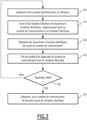
- control device 20 and more generally of the transmission installation 10, will now be explained with regard to the figure 2 representing a flowchart of the method of controlling the communication system 14, the method being implemented by the control device 10, as well as the Figure 3 representing a chronogram of said control method according to the invention.
- control device 20 When the user 16 receives the communication system 14, such as the Atom key, he begins by authenticating himself with the control device 20 (arrow F1 at the Figure 3 ), the control device 20 being for example formed of the user's mobile phone or electronic tablet, running a corresponding dedicated control software application.
- the control device 20 acquires, via its acquisition module 30, the first identifier relating to the user 16.
- the first identifier is for example acquired from the authentication information previously entered by the user 16.
- the authentication information is for example an email address and an associated password of the user 16.
- the acquisition step 100 includes the transmission, by the acquisition module 30, of said authentication information to the supervision equipment 22 so that it verifies its validity, then in the event of positive verification by the supervision equipment 22, the return transmission of the first unique identifier of the user 16 from the equipment 22 to the control device 20, in particular its acquisition module 30.
- control device 20 establishes communication (arrow F2 at the Figure 3 ) with the communication system 14 via the second data link 28, for example communication conforming to the Bluetooth standard, preferably the Bluetooth Low Energy standard.
- control device 20 When communication between the control device 20 and the communication system 14 is established, the control device 20 optionally performs a following step 110 of sending the request to obtain the second and third identifiers intended for the communication system 14 (arrow F3 at the Figure 3 ). This optional sending is carried out by the sending module 36.
- the control device 20 then passes to the reception step 120, during which the reception module 32 receives the second and third identifiers from the communication system 14 (arrow F4 at the Figure 3 ), for example in response to the obtain request previously sent during sending step 110.
- the second and third identifiers are preferably received in the form of at least one encrypted message, the encryption being for example carried out using the first encryption key 60.
- the second and third identifiers received then make it possible to uniquely identify the communication system 14 on the one hand and the electric meter 12 on the other hand.
- control device 20 then performs, during the test step 130 and via its test module 34, a validity test of the pairing of the communication system 14 with the electric meter 12 from the first, second and third identifiers.
- This validity test then makes it possible to check the consistency between the first, second and third identifiers received, that is to say that the second identifier which uniquely identifies the communication system 14 corresponds to the third identifier which identifies it. electric meter 12 in a unique manner, and this for the user 16 identified by the first identifier, or in other words that the communication system 14 is indeed designed to be coupled to said electric meter 12 of said user 16.
- the test step 130 then includes, for example, the transmission, to the electronic supervision equipment 22, of the request for validation of the triplet formed by the first, second and third identifiers (arrow F5 at the Figure 3 ).
- This validation request is preferably sent in the form of at least one encrypted message, the encryption being for example carried out using the second encryption key 62.
- the second encryption key 62 is preferably identical to the first key encryption 60, the encrypted message, transmitted by the test module 34 to the supervision equipment 22, comprising the first identifier, as well as the encrypted message received from the communication system 14 and containing the second and third identifiers.
- the supervision equipment 22 If the validity of the triplet formed by the first, second and third identifiers is confirmed by the supervision equipment 22, then it issues - in response to this validation request - a validation of said triplet (arrow F6 at the Figure 3 ) to the device control 20, in particular of its test module 34. The validity test of the pairing is then positive in the event of reception by the test module 34 of said validation of the triplet.
- the triplet of the first, second and third identifiers is then frozen and protected in a corresponding memory of the supervision equipment 22.
- This triplet cannot be broken, that is to say modified or altered, without authorization explicit from the supervision equipment 22.
- modification authorization is for example provided in the event of a malfunction of the communication system 14, requiring another communication system 14 to be coupled to the electric meter 12.
- the control device 20 determines, during step 140 and via its test module 34, whether the pairing between the communication system 14 and the electric meter 12 is valid, that is to say whether the test validity carried out during the previous step 130 is positive or not.
- the control device 20 returns to initial step 100, in order to carry out if necessary, another pairing, the current pairing being inhibited, that is to say prohibited, by the test module 34, following the negative validity test.
- the control device 20 then proceeds to the next step 150 during which the obtaining module 38 obtains - preferably regularly - data from the electric meter 12, such as electricity consumption data, from the communication system 14, and from preferably via supervision equipment 22.
- the obtaining step 150 includes for example the transmission via the communication system 14 of said data from the electric meter 12 to the supervision equipment 22 (arrow F7 at the Figure 3 ), followed by the retransmission of said data by the supervision equipment 22 to the control device 20, in particular its obtaining module 38 (arrow F8 at the Figure 3 ).
- the transmission of data from the electric meter 12 from the communication system 14 to the supervision equipment 22 is preferably carried out in the form of at least one encrypted message, the encryption being for example carried out using using the third encryption key 64.
- the subsequent retransmission of this data between the supervision equipment 22 and the control device 20 is preferably also carried out in the form of at least one encrypted message, the encryption being for example carried out at using the fourth encryption key 66.
- This obtaining of the data from the electric meter 12 in the form of encrypted message(s) allows then further improve data security.
- the third encryption key 64 is distinct from the fourth encryption key 66, these encryption keys 64, 66 being themselves distinct from the first and second encryption keys 60, 62.
- Each transmission of data from the electric meter 12, such as electricity consumption data, by the communication system 14 to the supervision equipment 22 preferably also includes the second and third identifiers. This then allows the supervision equipment 22 to check regularly, preferably each time data is received from the communication system 14, that the communication system-electric meter pair remains valid for each new transmission of data from the meter. electric 12.
- the control device 20 and the control method according to the invention then make it possible to improve the confidentiality and protection of data, such as electricity consumption data, from the electric meter 12. They make it possible in particular to verify that, when of the coupling between the communication system 14 and the electric meter 12, then with each transmission of data from the communication system 14, that the data reported from the electric meter 12 actually comes from the electric meter corresponding to the user 16 and that this transmission is carried out via the communication system 14 which is designed to be coupled to said electric meter 12.
- the control device 20 then makes it possible to avoid untimely spying on the data which could be carried out via the coupling between a communication system 14 and an electric meter 12 for which said communication system 14 would not be authorized.
Landscapes
- Engineering & Computer Science (AREA)
- Computer Networks & Wireless Communication (AREA)
- Selective Calling Equipment (AREA)
- Telephonic Communication Services (AREA)
- Arrangements For Transmission Of Measured Signals (AREA)
Claims (10)
- Steuerungsverfahren eines Kommunikationssystems (14) für einen Stromzähler (12), wobei das Kommunikationssystem (14) angepasst ist, um mit dem Stromzähler (12) verbunden zu werden und Daten von dem Stromzähler (12) an einen Benutzer (16) zu übertragen, wobei das Verfahren von einer elektronischen Steuerungsvorrichtung (20) durchgeführt wird und den folgenden Schritt umfasst:- Erfassen (100) einer ersten Kennung, wobei die erste Kennung geeignet ist, um den Benutzer (16) eindeutig zu identifizieren,dadurch gekennzeichnet, dass es ferner die folgenden Schritte umfasst:- Empfangen (120) einer zweiten und dritten Kennung von dem Kommunikationssystem (14), wobei die zweite Kennung geeignet ist, um das Kommunikationssystem (14) eindeutig zu identifizieren und die dritte Kennung geeignet ist, um den Stromzähler (12) eindeutig zu identifizieren, und- Testen (130) der Gültigkeit eines Koppelns des Kommunikationssystems (14) mit dem Stromzähler (12) abhängig von der ersten, zweiten und dritten Kennung, wobei das Koppeln bei einem positiven Test zugelassen und andernfalls gesperrt wird.
- Verfahren nach Anspruch 1, wobei das Verfahren vor dem Empfangsschritt (120) außerdem einen Schritt (110) des Sendens einer Anfrage zum Erlangen der zweiten und dritten Kennung an das Kommunikationssystem (14) umfasst,
wobei die zweite und die dritte Kennung dann in dem Empfangsschritt (120) als Antwort auf die Anforderung zum Erlangen empfangen werden. - Verfahren nach Anspruch 1 oder 2, wobei, wenn das Koppeln des Kommunikationssystems (14) mit dem Stromzähler (12) nach dem Testschritt (130) autorisiert ist, das Verfahren ferner einen weiteren Schritt (150) zum Erlangen von Daten von dem Stromzähler (12), wie z. B. Stromverbrauchsdaten, über das Kommunikationssystem (14) umfasst.
- Verfahren nach einem der vorherigen Ansprüche, wobei der Testschritt (130) das Senden einer Anfrage an eine elektronische Überwachungsausrüstung (22) zur Validierung eines Tripels umfasst, das gebildet wird von der ersten, zweiten und dritten Kennung, wobei der Test einer Gültigkeit des Koppelns anschließend positiv ist, wenn eine Validierung des Tripels seitens der Überwachungsausrüstung (22) und als Antwort auf die Validierungsanfrage empfangen wird.
- Verfahren nach Anspruch 4, wobei in dem Testschritt (130) die Validierungsanfrage in Form mindestens einer verschlüsselten Nachricht ausgegeben wird.
- Computerprogramm, umfassend Softwareanweisungen, die, wenn sie von einem Computer ausgeführt werden, ein Verfahren nach einem der vorherigen Ansprüche implementieren.
- Elektronische Vorrichtung (20) zum Steuern eines Kommunikationssystems (14) für einen Stromzähler (12), wobei das Kommunikationssystem (14) angepasst ist, um mit dem Stromzähler (12) verbunden zu werden und Daten von dem Stromzähler an einen Benutzer (16) zu übertragen, die Steuerungsvorrichtung (20) umfassend:- ein Erfassungsmodul (30), das konfiguriert ist, um eine erste Kennung zu erfassen, wobei die erste Kennung geeignet ist, um den Benutzer (16) eindeutig zu identifizieren, dadurch gekennzeichnet, dass es ferner Folgendes umfasst:- ein Empfangsmodul (32), das konfiguriert ist, um eine zweite und eine dritte Kennung von dem Kommunikationssystem (14) zu empfangen, wobei die zweite Kennung geeignet ist, um das Kommunikationssystem (14) eindeutig zu identifizieren und die dritte Kennung geeignet ist, um den Stromzähler (12) eindeutig zu identifizieren, und- ein Testmodul (34), das konfiguriert ist, um die Gültigkeit eines Koppelns des Kommunikationssystems (14) mit dem Stromzähler (12) abhängig von der ersten, der zweiten und der dritten Kennung zu testen; wobei das Koppeln im Falle eines positiven Tests zugelassen und andernfalls gesperrt wird.
- Elektronische Anlage (10) zur Übertragung von Daten, die von einem Stromzähler (12) stammen, die Übertragungsanlage (10) umfassend:- ein Kommunikationssystem (14), das angepasst ist, um mit dem Stromzähler (12) verbunden zu werden und Daten von dem Stromzähler (12) an einen Benutzer (16) zu übertragen, und- eine elektronische Vorrichtung (20) zur Steuerung des Kommunikationssystems (14), dadurch gekennzeichnet, dass die Steuerungsvorrichtung (20) gemäß dem vorherigen Anspruch ist.
- Anlage (10) nach Anspruch 8, wobei das Kommunikationssystem (14) ein ERL-Kommunikationssystem ist, für Linky™-Funksender, wobei der Stromzähler (12) ein elektronischer Zähler Linky™ ist, der mit einer TCI-Schnittstelle, für Tele-Client-Information, ausgestattet ist, über die die Daten ausgegeben werden, die geeignet sind, um von dem Kommunikationssystem (14) übertragen zu werden.
- Anlage (10) nach Anspruch 8 oder 9, wobei die Sendeanlage (10) ferner eine elektronische Überwachungsausrüstung (22) umfasst, die einerseits mit dem Kommunikationssystem (14) und andererseits über ein Kommunikationsnetz (18) mit der elektronischen Steuerungsvorrichtung (20) verbunden ist.
Priority Applications (1)
| Application Number | Priority Date | Filing Date | Title |
|---|---|---|---|
| EP20210357.8A EP4007290B1 (de) | 2020-11-27 | 2020-11-27 | Verfahren und elektronisches gerät zur steuerung eines kommunikationssystems für einen stromzähler, entsprechendes computerprogramm und entsprechende elektronische datenübertragungsanlage |
Applications Claiming Priority (1)
| Application Number | Priority Date | Filing Date | Title |
|---|---|---|---|
| EP20210357.8A EP4007290B1 (de) | 2020-11-27 | 2020-11-27 | Verfahren und elektronisches gerät zur steuerung eines kommunikationssystems für einen stromzähler, entsprechendes computerprogramm und entsprechende elektronische datenübertragungsanlage |
Publications (2)
| Publication Number | Publication Date |
|---|---|
| EP4007290A1 EP4007290A1 (de) | 2022-06-01 |
| EP4007290B1 true EP4007290B1 (de) | 2023-10-04 |
Family
ID=73642696
Family Applications (1)
| Application Number | Title | Priority Date | Filing Date |
|---|---|---|---|
| EP20210357.8A Active EP4007290B1 (de) | 2020-11-27 | 2020-11-27 | Verfahren und elektronisches gerät zur steuerung eines kommunikationssystems für einen stromzähler, entsprechendes computerprogramm und entsprechende elektronische datenübertragungsanlage |
Country Status (1)
| Country | Link |
|---|---|
| EP (1) | EP4007290B1 (de) |
Families Citing this family (2)
| Publication number | Priority date | Publication date | Assignee | Title |
|---|---|---|---|---|
| CN115474107A (zh) * | 2022-09-15 | 2022-12-13 | 浙江正泰仪器仪表有限责任公司 | 一种智能电能表通信方法及装置、设备、存储介质 |
| CN120378774B (zh) * | 2025-06-25 | 2025-09-30 | 杭州海兴电力科技股份有限公司 | 一种表计任务配置方法及系统 |
Family Cites Families (3)
| Publication number | Priority date | Publication date | Assignee | Title |
|---|---|---|---|---|
| DE102010044500A1 (de) * | 2010-09-06 | 2012-03-08 | Metrona Wärmemesser Union Gmbh | Verfahren, Vorrichtung und Vorrichtungsanordnung zur selektiven Bereitstellung von Verbrauchsdaten |
| EP2515552A1 (de) * | 2011-04-18 | 2012-10-24 | Nagravision S.A. | Überwachungsmodul für sicheren EVU-Zähler |
| FR3058006B1 (fr) | 2016-10-21 | 2018-12-07 | Esoftthings | Dispositif d’alimentation electrique et systeme de communication correspondant. |
-
2020
- 2020-11-27 EP EP20210357.8A patent/EP4007290B1/de active Active
Also Published As
| Publication number | Publication date |
|---|---|
| EP4007290A1 (de) | 2022-06-01 |
Similar Documents
| Publication | Publication Date | Title |
|---|---|---|
| EP3152860B1 (de) | Verfahren zur authentifizierung einer ersten elektronischen einheit durch eine zweite elektronische einheit und dieses verfahren umsetzende elektronische einheit | |
| FR3036913A1 (fr) | Procede de controle d'acces a un service | |
| WO2011051595A1 (fr) | Procédé et agent client pour contrôler l'utilisation d'un contenu protégé | |
| FR3066666A1 (fr) | Procede de securisation d'une communication sans gestion d'etats | |
| EP4007290B1 (de) | Verfahren und elektronisches gerät zur steuerung eines kommunikationssystems für einen stromzähler, entsprechendes computerprogramm und entsprechende elektronische datenübertragungsanlage | |
| EP3308564B1 (de) | Verfahren zum laden einer virtuellen schlüssels und zugehöriges benutzerendgerät | |
| EP3743871A1 (de) | Sicheres system für transaktionen zwischen endgeräten | |
| EP3314596B1 (de) | Verfahren zur steuerung einer funktion eines fahrzeugs mittels eines benutzerendgeräts | |
| EP3375133A1 (de) | Verfahren zur sicherung und authentifizierung einer telekommunikation | |
| WO2015082607A1 (fr) | Capteur de mesure, installation de mesure comprenant un tel capteur et un serveur, procédé d'échange de données et produit programme d'ordinateur associés | |
| EP3809388B1 (de) | Durchflusszähler zur kommunikation mit einem elektromechanischen ventil | |
| WO2006125885A1 (fr) | Procede de controle de la connexion d'un peripherique a un point d'acces, point d'acces et peripherique correspondants | |
| EP3667530A1 (de) | Sicherer zugriff auf geschriebene daten aus einem benutzerklemmen | |
| FR3057973A1 (fr) | Procede d'installation d'un certificat dans un calculateur de vehicule, calculateur et systeme associes | |
| FR3096813A1 (fr) | Procédé et dispositif électronique de pilotage d’un système de communication pour compteur électrique, programme d’ordinateur et installation électronique de transmission associés | |
| EP4207675B1 (de) | Verfahren zum senden und empfangen von verbrauchsdaten und vorrichtungen zur durchführung des verfahrens | |
| WO2017085284A1 (fr) | Unite electronique, systeme comprenant une telle unite electronique et procede de deverrouiillage | |
| FR3068854A1 (fr) | Gestion de communication entre un terminal et un serveur reseau | |
| EP2911365B1 (de) | Verfahren und System zur Sicherung von Transaktionen, die von einer Vielzahl von Diensten zwischen einem Mobilgerät eines Benutzers und einer Akzeptanzstelle angeboten werden | |
| EP3259159B1 (de) | Verfahren zur implementierung einer verbindung zwischen einer elektronischen slave-vorrichtung und elektronischen master-vorrichtung und zugehörige elektronische slave-vorrichtung | |
| FR3070776A1 (fr) | Enrolement perfectionne d'un equipement dans un reseau securise | |
| FR3074634A1 (fr) | Gestion de communication entre un terminal et un serveur d’un reseau | |
| WO2020174137A1 (fr) | Procédé et dispositif de cryptographie symétrique pour calculateur de véhicule | |
| FR3113331A1 (fr) | Procédé et dispositif électronique de validation d’un appairage d’un système de communication avec un compteur électrique et programme d’ordinateur associé | |
| EP4298759A1 (de) | Verfahren zum sicheren austausch zwischen einem zugangskontrollleser, iot hub und einer datenverarbeitungseinheit |
Legal Events
| Date | Code | Title | Description |
|---|---|---|---|
| PUAI | Public reference made under article 153(3) epc to a published international application that has entered the european phase |
Free format text: ORIGINAL CODE: 0009012 |
|
| STAA | Information on the status of an ep patent application or granted ep patent |
Free format text: STATUS: THE APPLICATION HAS BEEN PUBLISHED |
|
| AK | Designated contracting states |
Kind code of ref document: A1 Designated state(s): AL AT BE BG CH CY CZ DE DK EE ES FI FR GB GR HR HU IE IS IT LI LT LU LV MC MK MT NL NO PL PT RO RS SE SI SK SM TR |
|
| STAA | Information on the status of an ep patent application or granted ep patent |
Free format text: STATUS: REQUEST FOR EXAMINATION WAS MADE |
|
| 17P | Request for examination filed |
Effective date: 20221114 |
|
| RBV | Designated contracting states (corrected) |
Designated state(s): AL AT BE BG CH CY CZ DE DK EE ES FI FR GB GR HR HU IE IS IT LI LT LU LV MC MK MT NL NO PL PT RO RS SE SI SK SM TR |
|
| GRAP | Despatch of communication of intention to grant a patent |
Free format text: ORIGINAL CODE: EPIDOSNIGR1 |
|
| STAA | Information on the status of an ep patent application or granted ep patent |
Free format text: STATUS: GRANT OF PATENT IS INTENDED |
|
| INTG | Intention to grant announced |
Effective date: 20230428 |
|
| P01 | Opt-out of the competence of the unified patent court (upc) registered |
Effective date: 20230522 |
|
| GRAS | Grant fee paid |
Free format text: ORIGINAL CODE: EPIDOSNIGR3 |
|
| GRAA | (expected) grant |
Free format text: ORIGINAL CODE: 0009210 |
|
| STAA | Information on the status of an ep patent application or granted ep patent |
Free format text: STATUS: THE PATENT HAS BEEN GRANTED |
|
| RBV | Designated contracting states (corrected) |
Designated state(s): AL AT BE BG CH CY CZ DE DK EE ES FI GB GR HR HU IE IS IT LI LT LU LV MC MK MT NL NO PL PT RO RS SE SI SK SM TR |
|
| AK | Designated contracting states |
Kind code of ref document: B1 Designated state(s): AL AT BE BG CH CY CZ DE DK EE ES FI GB GR HR HU IE IS IT LI LT LU LV MC MK MT NL NO PL PT RO RS SE SI SK SM TR |
|
| REG | Reference to a national code |
Ref country code: GB Ref legal event code: FG4D Free format text: NOT ENGLISH |
|
| REG | Reference to a national code |
Ref country code: CH Ref legal event code: EP |
|
| REG | Reference to a national code |
Ref country code: DE Ref legal event code: R096 Ref document number: 602020018561 Country of ref document: DE |
|
| REG | Reference to a national code |
Ref country code: IE Ref legal event code: FG4D Free format text: LANGUAGE OF EP DOCUMENT: FRENCH |
|
| REG | Reference to a national code |
Ref country code: LT Ref legal event code: MG9D |
|
| REG | Reference to a national code |
Ref country code: NL Ref legal event code: MP Effective date: 20231004 |
|
| PGFP | Annual fee paid to national office [announced via postgrant information from national office to epo] |
Ref country code: BE Payment date: 20231113 Year of fee payment: 4 |
|
| REG | Reference to a national code |
Ref country code: AT Ref legal event code: MK05 Ref document number: 1619052 Country of ref document: AT Kind code of ref document: T Effective date: 20231004 |
|
| PG25 | Lapsed in a contracting state [announced via postgrant information from national office to epo] |
Ref country code: NL Free format text: LAPSE BECAUSE OF FAILURE TO SUBMIT A TRANSLATION OF THE DESCRIPTION OR TO PAY THE FEE WITHIN THE PRESCRIBED TIME-LIMIT Effective date: 20231004 |
|
| PG25 | Lapsed in a contracting state [announced via postgrant information from national office to epo] |
Ref country code: GR Free format text: LAPSE BECAUSE OF FAILURE TO SUBMIT A TRANSLATION OF THE DESCRIPTION OR TO PAY THE FEE WITHIN THE PRESCRIBED TIME-LIMIT Effective date: 20240105 |
|
| PG25 | Lapsed in a contracting state [announced via postgrant information from national office to epo] |
Ref country code: IS Free format text: LAPSE BECAUSE OF FAILURE TO SUBMIT A TRANSLATION OF THE DESCRIPTION OR TO PAY THE FEE WITHIN THE PRESCRIBED TIME-LIMIT Effective date: 20240204 |
|
| PG25 | Lapsed in a contracting state [announced via postgrant information from national office to epo] |
Ref country code: LT Free format text: LAPSE BECAUSE OF FAILURE TO SUBMIT A TRANSLATION OF THE DESCRIPTION OR TO PAY THE FEE WITHIN THE PRESCRIBED TIME-LIMIT Effective date: 20231004 |
|
| PG25 | Lapsed in a contracting state [announced via postgrant information from national office to epo] |
Ref country code: AT Free format text: LAPSE BECAUSE OF FAILURE TO SUBMIT A TRANSLATION OF THE DESCRIPTION OR TO PAY THE FEE WITHIN THE PRESCRIBED TIME-LIMIT Effective date: 20231004 |
|
| PG25 | Lapsed in a contracting state [announced via postgrant information from national office to epo] |
Ref country code: ES Free format text: LAPSE BECAUSE OF FAILURE TO SUBMIT A TRANSLATION OF THE DESCRIPTION OR TO PAY THE FEE WITHIN THE PRESCRIBED TIME-LIMIT Effective date: 20231004 |
|
| PG25 | Lapsed in a contracting state [announced via postgrant information from national office to epo] |
Ref country code: LT Free format text: LAPSE BECAUSE OF FAILURE TO SUBMIT A TRANSLATION OF THE DESCRIPTION OR TO PAY THE FEE WITHIN THE PRESCRIBED TIME-LIMIT Effective date: 20231004 Ref country code: IS Free format text: LAPSE BECAUSE OF FAILURE TO SUBMIT A TRANSLATION OF THE DESCRIPTION OR TO PAY THE FEE WITHIN THE PRESCRIBED TIME-LIMIT Effective date: 20240204 Ref country code: GR Free format text: LAPSE BECAUSE OF FAILURE TO SUBMIT A TRANSLATION OF THE DESCRIPTION OR TO PAY THE FEE WITHIN THE PRESCRIBED TIME-LIMIT Effective date: 20240105 Ref country code: ES Free format text: LAPSE BECAUSE OF FAILURE TO SUBMIT A TRANSLATION OF THE DESCRIPTION OR TO PAY THE FEE WITHIN THE PRESCRIBED TIME-LIMIT Effective date: 20231004 Ref country code: BG Free format text: LAPSE BECAUSE OF FAILURE TO SUBMIT A TRANSLATION OF THE DESCRIPTION OR TO PAY THE FEE WITHIN THE PRESCRIBED TIME-LIMIT Effective date: 20240104 Ref country code: AT Free format text: LAPSE BECAUSE OF FAILURE TO SUBMIT A TRANSLATION OF THE DESCRIPTION OR TO PAY THE FEE WITHIN THE PRESCRIBED TIME-LIMIT Effective date: 20231004 Ref country code: PT Free format text: LAPSE BECAUSE OF FAILURE TO SUBMIT A TRANSLATION OF THE DESCRIPTION OR TO PAY THE FEE WITHIN THE PRESCRIBED TIME-LIMIT Effective date: 20240205 |
|
| PG25 | Lapsed in a contracting state [announced via postgrant information from national office to epo] |
Ref country code: SE Free format text: LAPSE BECAUSE OF FAILURE TO SUBMIT A TRANSLATION OF THE DESCRIPTION OR TO PAY THE FEE WITHIN THE PRESCRIBED TIME-LIMIT Effective date: 20231004 Ref country code: RS Free format text: LAPSE BECAUSE OF FAILURE TO SUBMIT A TRANSLATION OF THE DESCRIPTION OR TO PAY THE FEE WITHIN THE PRESCRIBED TIME-LIMIT Effective date: 20231004 Ref country code: PL Free format text: LAPSE BECAUSE OF FAILURE TO SUBMIT A TRANSLATION OF THE DESCRIPTION OR TO PAY THE FEE WITHIN THE PRESCRIBED TIME-LIMIT Effective date: 20231004 Ref country code: NO Free format text: LAPSE BECAUSE OF FAILURE TO SUBMIT A TRANSLATION OF THE DESCRIPTION OR TO PAY THE FEE WITHIN THE PRESCRIBED TIME-LIMIT Effective date: 20240104 Ref country code: LV Free format text: LAPSE BECAUSE OF FAILURE TO SUBMIT A TRANSLATION OF THE DESCRIPTION OR TO PAY THE FEE WITHIN THE PRESCRIBED TIME-LIMIT Effective date: 20231004 Ref country code: HR Free format text: LAPSE BECAUSE OF FAILURE TO SUBMIT A TRANSLATION OF THE DESCRIPTION OR TO PAY THE FEE WITHIN THE PRESCRIBED TIME-LIMIT Effective date: 20231004 |
|
| REG | Reference to a national code |
Ref country code: DE Ref legal event code: R119 Ref document number: 602020018561 Country of ref document: DE |
|
| REG | Reference to a national code |
Ref country code: CH Ref legal event code: PL |
|
| PG25 | Lapsed in a contracting state [announced via postgrant information from national office to epo] |
Ref country code: DK Free format text: LAPSE BECAUSE OF FAILURE TO SUBMIT A TRANSLATION OF THE DESCRIPTION OR TO PAY THE FEE WITHIN THE PRESCRIBED TIME-LIMIT Effective date: 20231004 |
|
| PG25 | Lapsed in a contracting state [announced via postgrant information from national office to epo] |
Ref country code: LU Free format text: LAPSE BECAUSE OF NON-PAYMENT OF DUE FEES Effective date: 20231127 |
|
| PG25 | Lapsed in a contracting state [announced via postgrant information from national office to epo] |
Ref country code: CH Free format text: LAPSE BECAUSE OF NON-PAYMENT OF DUE FEES Effective date: 20231130 |
|
| PG25 | Lapsed in a contracting state [announced via postgrant information from national office to epo] |
Ref country code: CZ Free format text: LAPSE BECAUSE OF FAILURE TO SUBMIT A TRANSLATION OF THE DESCRIPTION OR TO PAY THE FEE WITHIN THE PRESCRIBED TIME-LIMIT Effective date: 20231004 |
|
| PG25 | Lapsed in a contracting state [announced via postgrant information from national office to epo] |
Ref country code: SK Free format text: LAPSE BECAUSE OF FAILURE TO SUBMIT A TRANSLATION OF THE DESCRIPTION OR TO PAY THE FEE WITHIN THE PRESCRIBED TIME-LIMIT Effective date: 20231004 |
|
| PG25 | Lapsed in a contracting state [announced via postgrant information from national office to epo] |
Ref country code: SM Free format text: LAPSE BECAUSE OF FAILURE TO SUBMIT A TRANSLATION OF THE DESCRIPTION OR TO PAY THE FEE WITHIN THE PRESCRIBED TIME-LIMIT Effective date: 20231004 Ref country code: SK Free format text: LAPSE BECAUSE OF FAILURE TO SUBMIT A TRANSLATION OF THE DESCRIPTION OR TO PAY THE FEE WITHIN THE PRESCRIBED TIME-LIMIT Effective date: 20231004 Ref country code: RO Free format text: LAPSE BECAUSE OF FAILURE TO SUBMIT A TRANSLATION OF THE DESCRIPTION OR TO PAY THE FEE WITHIN THE PRESCRIBED TIME-LIMIT Effective date: 20231004 Ref country code: LU Free format text: LAPSE BECAUSE OF NON-PAYMENT OF DUE FEES Effective date: 20231127 Ref country code: IT Free format text: LAPSE BECAUSE OF FAILURE TO SUBMIT A TRANSLATION OF THE DESCRIPTION OR TO PAY THE FEE WITHIN THE PRESCRIBED TIME-LIMIT Effective date: 20231004 Ref country code: EE Free format text: LAPSE BECAUSE OF FAILURE TO SUBMIT A TRANSLATION OF THE DESCRIPTION OR TO PAY THE FEE WITHIN THE PRESCRIBED TIME-LIMIT Effective date: 20231004 Ref country code: DK Free format text: LAPSE BECAUSE OF FAILURE TO SUBMIT A TRANSLATION OF THE DESCRIPTION OR TO PAY THE FEE WITHIN THE PRESCRIBED TIME-LIMIT Effective date: 20231004 Ref country code: CZ Free format text: LAPSE BECAUSE OF FAILURE TO SUBMIT A TRANSLATION OF THE DESCRIPTION OR TO PAY THE FEE WITHIN THE PRESCRIBED TIME-LIMIT Effective date: 20231004 Ref country code: CH Free format text: LAPSE BECAUSE OF NON-PAYMENT OF DUE FEES Effective date: 20231130 |
|
| PLBE | No opposition filed within time limit |
Free format text: ORIGINAL CODE: 0009261 |
|
| STAA | Information on the status of an ep patent application or granted ep patent |
Free format text: STATUS: NO OPPOSITION FILED WITHIN TIME LIMIT |
|
| PG25 | Lapsed in a contracting state [announced via postgrant information from national office to epo] |
Ref country code: MC Free format text: LAPSE BECAUSE OF FAILURE TO SUBMIT A TRANSLATION OF THE DESCRIPTION OR TO PAY THE FEE WITHIN THE PRESCRIBED TIME-LIMIT Effective date: 20231004 |
|
| PG25 | Lapsed in a contracting state [announced via postgrant information from national office to epo] |
Ref country code: MC Free format text: LAPSE BECAUSE OF FAILURE TO SUBMIT A TRANSLATION OF THE DESCRIPTION OR TO PAY THE FEE WITHIN THE PRESCRIBED TIME-LIMIT Effective date: 20231004 |
|
| 26N | No opposition filed |
Effective date: 20240705 |
|
| REG | Reference to a national code |
Ref country code: IE Ref legal event code: MM4A |
|
| PG25 | Lapsed in a contracting state [announced via postgrant information from national office to epo] |
Ref country code: DE Free format text: LAPSE BECAUSE OF NON-PAYMENT OF DUE FEES Effective date: 20240601 Ref country code: IE Free format text: LAPSE BECAUSE OF NON-PAYMENT OF DUE FEES Effective date: 20231127 |
|
| PG25 | Lapsed in a contracting state [announced via postgrant information from national office to epo] |
Ref country code: SI Free format text: LAPSE BECAUSE OF FAILURE TO SUBMIT A TRANSLATION OF THE DESCRIPTION OR TO PAY THE FEE WITHIN THE PRESCRIBED TIME-LIMIT Effective date: 20231004 |
|
| PG25 | Lapsed in a contracting state [announced via postgrant information from national office to epo] |
Ref country code: SI Free format text: LAPSE BECAUSE OF FAILURE TO SUBMIT A TRANSLATION OF THE DESCRIPTION OR TO PAY THE FEE WITHIN THE PRESCRIBED TIME-LIMIT Effective date: 20231004 Ref country code: IE Free format text: LAPSE BECAUSE OF NON-PAYMENT OF DUE FEES Effective date: 20231127 Ref country code: DE Free format text: LAPSE BECAUSE OF NON-PAYMENT OF DUE FEES Effective date: 20240601 |
|
| PG25 | Lapsed in a contracting state [announced via postgrant information from national office to epo] |
Ref country code: FI Free format text: LAPSE BECAUSE OF FAILURE TO SUBMIT A TRANSLATION OF THE DESCRIPTION OR TO PAY THE FEE WITHIN THE PRESCRIBED TIME-LIMIT Effective date: 20231004 |
|
| GBPC | Gb: european patent ceased through non-payment of renewal fee |
Effective date: 20241127 |
|
| PG25 | Lapsed in a contracting state [announced via postgrant information from national office to epo] |
Ref country code: CY Free format text: LAPSE BECAUSE OF FAILURE TO SUBMIT A TRANSLATION OF THE DESCRIPTION OR TO PAY THE FEE WITHIN THE PRESCRIBED TIME-LIMIT; INVALID AB INITIO Effective date: 20201127 |
|
| PG25 | Lapsed in a contracting state [announced via postgrant information from national office to epo] |
Ref country code: HU Free format text: LAPSE BECAUSE OF FAILURE TO SUBMIT A TRANSLATION OF THE DESCRIPTION OR TO PAY THE FEE WITHIN THE PRESCRIBED TIME-LIMIT; INVALID AB INITIO Effective date: 20201127 |
|
| REG | Reference to a national code |
Ref country code: BE Ref legal event code: MM Effective date: 20241130 |
|
| PG25 | Lapsed in a contracting state [announced via postgrant information from national office to epo] |
Ref country code: GB Free format text: LAPSE BECAUSE OF NON-PAYMENT OF DUE FEES Effective date: 20241127 Ref country code: BE Free format text: LAPSE BECAUSE OF NON-PAYMENT OF DUE FEES Effective date: 20241130 |
|
| PG25 | Lapsed in a contracting state [announced via postgrant information from national office to epo] |
Ref country code: TR Free format text: LAPSE BECAUSE OF FAILURE TO SUBMIT A TRANSLATION OF THE DESCRIPTION OR TO PAY THE FEE WITHIN THE PRESCRIBED TIME-LIMIT Effective date: 20231004 |