EP4007299B1 - Audioausgabe mit mehreren unterschiedlichen wandlern - Google Patents
Audioausgabe mit mehreren unterschiedlichen wandlern Download PDFInfo
- Publication number
- EP4007299B1 EP4007299B1 EP20209790.3A EP20209790A EP4007299B1 EP 4007299 B1 EP4007299 B1 EP 4007299B1 EP 20209790 A EP20209790 A EP 20209790A EP 4007299 B1 EP4007299 B1 EP 4007299B1
- Authority
- EP
- European Patent Office
- Prior art keywords
- audio output
- frequency
- cut
- output channels
- audio
- Prior art date
- Legal status (The legal status is an assumption and is not a legal conclusion. Google has not performed a legal analysis and makes no representation as to the accuracy of the status listed.)
- Active
Links
Images


Classifications
-
- H—ELECTRICITY
- H04—ELECTRIC COMMUNICATION TECHNIQUE
- H04R—LOUDSPEAKERS, MICROPHONES, GRAMOPHONE PICK-UPS OR LIKE ACOUSTIC ELECTROMECHANICAL TRANSDUCERS; ELECTRIC HEARING AIDS; PUBLIC ADDRESS SYSTEMS
- H04R3/00—Circuits for transducers
- H04R3/12—Circuits for transducers for distributing signals to two or more loudspeakers
- H04R3/14—Cross-over networks
-
- H—ELECTRICITY
- H04—ELECTRIC COMMUNICATION TECHNIQUE
- H04R—LOUDSPEAKERS, MICROPHONES, GRAMOPHONE PICK-UPS OR LIKE ACOUSTIC ELECTROMECHANICAL TRANSDUCERS; ELECTRIC HEARING AIDS; PUBLIC ADDRESS SYSTEMS
- H04R5/00—Stereophonic arrangements
- H04R5/033—Headphones for stereophonic communication
-
- H—ELECTRICITY
- H04—ELECTRIC COMMUNICATION TECHNIQUE
- H04R—LOUDSPEAKERS, MICROPHONES, GRAMOPHONE PICK-UPS OR LIKE ACOUSTIC ELECTROMECHANICAL TRANSDUCERS; ELECTRIC HEARING AIDS; PUBLIC ADDRESS SYSTEMS
- H04R1/00—Details of transducers, loudspeakers or microphones
- H04R1/10—Earpieces; Attachments therefor ; Earphones; Monophonic headphones
- H04R1/1041—Mechanical or electronic switches, or control elements
-
- H—ELECTRICITY
- H04—ELECTRIC COMMUNICATION TECHNIQUE
- H04R—LOUDSPEAKERS, MICROPHONES, GRAMOPHONE PICK-UPS OR LIKE ACOUSTIC ELECTROMECHANICAL TRANSDUCERS; ELECTRIC HEARING AIDS; PUBLIC ADDRESS SYSTEMS
- H04R1/00—Details of transducers, loudspeakers or microphones
- H04R1/10—Earpieces; Attachments therefor ; Earphones; Monophonic headphones
- H04R1/1083—Reduction of ambient noise
-
- H—ELECTRICITY
- H04—ELECTRIC COMMUNICATION TECHNIQUE
- H04R—LOUDSPEAKERS, MICROPHONES, GRAMOPHONE PICK-UPS OR LIKE ACOUSTIC ELECTROMECHANICAL TRANSDUCERS; ELECTRIC HEARING AIDS; PUBLIC ADDRESS SYSTEMS
- H04R2460/00—Details of hearing devices, i.e. of ear- or headphones covered by H04R1/10 or H04R5/033 but not provided for in any of their subgroups, or of hearing aids covered by H04R25/00 but not provided for in any of its subgroups
- H04R2460/13—Hearing devices using bone conduction transducers
Definitions
- Embodiments of the present disclosure relate to providing audio output using multiple different transducers.
- An audio output apparatus can be configured to render sound for a user of the apparatus into different audio output channels using different associated transducers.
- the different transducers can, for example, be used for different specific frequency ranges.
- a filter can be used to route audio signals below a cross-over frequency to a transducer optimised for lower frequency audio output and route audio signals above the cross-over frequency to a different transducer optimised for higher frequency audio output.
- the cross-over frequency is fixed by the different specific frequency ranges of the transducers used.
- the filter is replaced with one that has a fixed cross-over frequency optimised for the new transducers.
- US 2013/051585 A1 discloses (abstract) an apparatus including an air-conduction transducer and a bone conduction transducer.
- the air-conduction transducer is configured to convert a first frequency band component of an electrical audio signal into acoustic energy to be delivered to an ear canal of a user.
- the bone conduction transducer is configured to convert a second, at least partially different, frequency band component of the electrical audio signal into mechanical energy to be delivered to a skull of the user.
- the apparatus is configured to deliver both forms of the energies to the user at a substantially same time to provide a combined audio delivery result to the user.
- a head-mounted audio output apparatus as according to claim 1.
- the means for automatically changing a cut-off frequency of at least the first one of the audio output channels is configured to change the cut-off frequency of the first one of the audio output channels in dependence on at least a sensed environmental value at a position of the head-mounted audio output apparatus.
- the means for automatically changing a cut-off frequency of at least the first one of the audio output channels is configured to increase the cross-over frequency between a lower frequency audio output channel and a higher frequency audio output channel such that a bandwidth of the lower frequency audio output channel increases and a bandwidth of the higher frequency audio output channel decreases.
- the hybrid audio system is configured to render sound for a left ear of the user into a first audio output channel using an associated first transducer and into a second audio output channel using an associated second transducer and is configured to render sound for a right ear of the user into a third audio output channel using an associated third transducer and into a fourth audio output channel using an associated fourth transducer.
- a first set of different audio output channels comprising the first audio output channel and the second audio output channel and a second set of different audio output channels comprising the third audio output channel and the fourth audio output channel are controlled to render one or more audio objects.
- the first audio output channel, the second audio output channel, the third audio output channel and the fourth audio output channel are controlled to render one or more audio objects.
- the means for automatically changing a cut-off frequency of at least the first one of the audio output channels is configured to automatically change the cut-off frequency of the first one of the audio output channels in dependence upon a dynamic assessment of one or more of:
- the means for automatically changing a cut-off frequency of at least the first one of the audio output channels is configured to automatically change the cut-off frequency of the first one of the audio output channels to increase a bandwidth of the first one of the audio output channels, in dependence upon impairment of a second one of the audio output channels.
- the means for automatically changing a cut-off frequency of at least the first one of the audio output channels is configured to automatically change the cut-off frequency of the first one of the audio output channels to optimize for hearability.
- the means for automatically changing a cut-off frequency of at least the first one of the audio output channels is configured to automatically change the cut-off frequency of the first one of the audio output channels in dependence upon a dynamic assessment of one or more of sensor output; noise; content for rendering.
- the means for automatically changing a cut-off frequency of at least the first one of the audio output channels is configured to automatically change the cut-off frequency of the first one of the audio output channels in dependence upon at least one of:
- FIG 1 illustrates an example of an audio output apparatus 10 comprising a hybrid audio system 20.
- the hybrid audio system 20 comprises multiple transducers 22, including a first transducer 22, and a second transducer 22 2 .
- the hybrid audio system 20 is configured to render sound for a user 200 of the apparatus 10 into different audio output channels 30 using different associated transducers 22.
- the different audio output channels 30 include a first audio output channel 30 1 associated with the first transducer 22, and a second audio output channel 30 2 associated with the second transducer 22 2 .
- the first transducer 22, renders sound for the user 200 into the associated first audio output channel 30 1 .
- the second transducer 22 2 renders sound for the user 200 into the associated second audio output channel 30 2 .
- the method of transduction used by the first transducer 22, and the second transducer 22 2 are different.
- the first transducer 22, is configured to produce vibrations in bone that transfer sound via a bone-conduction audio output channel 30 1 .
- the second transducer 22 2 is configured to produce pressure waves in air that transfer sound via an air-conduction audio output channel 30 2 .
- the apparatus 10 comprises means for automatically changing a cut-off frequency of at least the first audio output channel 30 1 in dependence upon the transducer associated with the first audio output channel 30 1 (the first transducer 22 1 ).
- the apparatus 10 can also comprise means for automatically changing a cut-off frequency of the second audio output channel 30z in dependence upon the transducer associated with the second audio output channel 30 2 (the second transducer 22 2 ).
- the means for automatically changing a cut-off frequency of the first audio output channel 30 1 and a cut-off frequency of the second audio output channel 30 2 can comprise a filter 24 and a filter controller 40.
- the filter 24 filters an audio signal 2 and produces a first audio signal 4 1 for driving the first transducer 22, and produces a second audio signal 4 2 for driving the second transducer 22 2 .
- the filter characteristics of the filter 24 are controlled by control signal 42 provided by the filter controller 40.
- the filter controller 40 is configured to control the filter 24 to change a cut-off frequency of the first audio signal 4 1 and therefore control the cut-off frequency of the first audio output channel 30 1 .
- the filter controller 40 is configured to control the filter 24 to change a cut-off frequency of the second audio signal 4 2 and therefore control the cut-off frequency of the second audio output channel 30 2 .
- the filter controller 40 can control the filter 24 to change an upper cut-off frequency f uco of the first audio signal 4 1 .
- the filter controller 40 can control the filter 24 to change a lower cut-off frequency f lco of the second audio signal 4 2 .
- the filter controller 40 is configured to automatically change a cut-off frequency of the first audio output channel 30 1 in dependence on a sensed environmental value 52 at a position of the audio output apparatus 10. In some but not necessarily all examples, the filter controller 40 is configured to automatically change a cut-off frequency of the second audio output channel 30 2 in dependence on the or a sensed environmental value 52.
- the apparatus 10 optionally comprises a sensor 50 configured to sense a parameter 102 of an exterior environment 100, at the position of the audio output apparatus 10, and provide the sensed environmental value 52 to the filter controller 40.
- the apparatus 10 is a worn apparatus. In some but not necessarily all examples, the apparatus 10 is a head-mounted apparatus.
- a head-mounted apparatus can, for example, be configured as an over-ear apparatus, an on-ear apparatus, an in-ear apparatus, or as a bud or pod.
- a head-mounted apparatus is headset.
- One example of a head-mounted apparatus is headphones.
- One example of a head-mounted apparatus is a head-worn mediated reality apparatus such as virtual reality (see-display) or augmented reality (see-through display) apparatus.
- the first transducer 22 is a bone-conduction transducer configured to render sound to a left ear 202 L of the user 200 of the apparatus 10 via a bone-conduction audio output channel 30 1 (not illustrated in FIG 10).
- the second transducer 22 2 is an air-conduction transducer configured to render sound to the left ear 202 L of the user 200 of the apparatus 10 via an air-conduction audio output channel 30 2 (not illustrated in FIG 10).
- the filter controller 40 is configured to automatically change, using control signal 42, a cross-over frequency associated with the first audio output channel 30 1 and the second audio output channel 30 2 .
- the filter 24 automatically adapts a cross-over frequency of the first audio output channel 30 1 and the second audio output channel 30 2 in response to the control signal 42.
- control signal 42 is automatically changed in dependence on a sensed environmental value 52 at a position of the audio output apparatus 10.
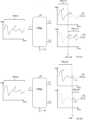
- the filter 24 splits a bandwidth BW of the audio signal 2 into two contiguous, mostly nonoverlapping parts for the different audio output channels 30 1 , 30 2 .
- the two parts are a lower frequency part BW L . and a higher frequency part BW H .
- the first audio signal 4 1 has been filtered to be a lower frequency signal. It has a bandwidth corresponding to the lower frequency part BW L .
- the cross-over frequency f xo corresponds to an upper cut-off frequency f uco of the first audio signal 4 1 .
- the second audio signal 4 2 has been filtered to be a higher frequency signal. It has a bandwidth corresponding to the higher frequency part BW H .
- the cross-over frequency f xo corresponds to a lower cut-off frequency f lco of the second audio signal 4 2 .
- the filter 24 filters the audio signal 2 and produces the first audio signal 4 1 for driving the first transducer 22, and produces the second audio signal 4 2 for driving the second transducer 22 2 .
- the filter characteristics of the filter 24 are controlled by control signal 42 provided by the filter controller 40.
- the filter controller 40 is configured to control the filter 24 to change the cross-over frequency of the first audio signal 4 1 and the second audio signal 4 2 . This determines the cross-over frequency between the first audio output channel 30 1 and the second audio output channel 30 2 .
- the cross-over frequency at time t1 ( FIG 2A ) is increased at time t2 ( FIG 2B ). This increases the bandwidth BW L of the lower frequency audio output channel 30 1 and decreases the bandwidth BW H of the higher frequency audio output channel 30 2 .
- FIGs 2A and 2B illustrate an example of a method.
- the method uses features described previously with reference to FIG 1 .
- the method comprises, as illustrated in FIG 2A at time t1, using a hybrid audio system 20 comprising multiple transducers 22 to render sound to a user 200 into different audio output channels 30, wherein a first audio output channel 30 1 , associated with a first transducer 22 1 , has a first cut-off frequency (f uco ) and wherein a second audio output channel 30 2 , associated with a second transducer 22 2 , different to the first transducer 22 1 , has a second cut-off frequency (f lco ).
- a hybrid audio system 20 comprising multiple transducers 22 to render sound to a user 200 into different audio output channels 30, wherein a first audio output channel 30 1 , associated with a first transducer 22 1 , has a first cut-off frequency (f uco ) and wherein a second audio output channel 30 2 , associated with a second transducer
- the method comprises changing the first cut-off frequency (f uco ) to a different first cut-off frequency (f' uco ) and changing the second cut-off frequency to a different second cut-off frequency (f' lco ), wherein the change of the first cut-off frequency (f uco ) to the different first cut-off frequency (f' uco ) (e.g. increase in upper frequency of passband, extension of lower frequency passband) is different from the change of the second cut-off frequency (f lco ) to the different second cut-off frequency (f' uco ) (e.g. increase in lower frequency of passband, contraction of higher frequency passband).
- the method then comprises, as illustrated in FIG 2B at time t2, using a hybrid audio system 20 comprising multiple transducers 22 to render sound to a user 200 into different audio output channels 30, wherein the first audio output channel 30 1 , associated with the first transducer 22 1 , has the different first cut-off frequency (f' uco ) and wherein the second audio output channel 30 2 , associated with the second transducer 22 2 , different to the first transducer 22 1 , has the different second cut-off frequency (f' lco ).
- the hybrid audio system 20 is configured to render sound for a right ear 202 R of the user 200 into a first audio output channel 30 1 using an associated first transducer 22, and into a second audio output channel 30 2 using an associated second transducer 22 2 and is configured to render sound for a left ear 202 L of the user 200 into a third audio output channel 30 3 using an associated third transducer 22 3 and into a fourth audio output channel 30 4 using an associated fourth transducer 22 4 .
- hybrid transducers 22 There are two different hybrid transducers 22 per ear 202. An equivalent pair of different hybrid transducers 22 can be used for each ear.
- the first bone-conduction transducer 22, and the third bone-conduction transducer 22 3 can be the same or similar.
- a bone-conduction transducer is configured to conduct energy representing the respective audio signal 4 1 , 4 3 to an ear 202 of the user 200 via the head bones of the user 200.
- An example of a bone-conduction transducer 22 1 , 22 3 is an electromagnetically controlled mechanical vibrator.
- the second air-conduction transducer 22 2 and the fourth air-conduction transducer 22 4 can be the same or similar.
- An air-conduction transducer is configured to conduct energy representing the respective audio signal 4 2 , 4 4 into an ear 202 of the user 200 via the open ear canal of the user 200.
- An example of an air-conduction transducer 22 2 , 22 4 is an electromagnetically controlled diaphragm.
- the apparatus 10 comprises a left part 12 L and a right part 12 R .
- the left part 12 L is positioned in, at or near a left ear 202 L of the user 200.
- the right part 12 R is positioned in, at or near a right ear 202 R of the user 200.
- Operation of the left part 12 L of the apparatus 10 can be the same as operation of the apparatus 10 as described in relation to FIGs 1 and 2A & 2B .
- Operation of the right part 12 R of the apparatus 10 can be the same as operation of the apparatus 10 as described in relation to FIGs 1 and 2A & 2B .
- the hybrid audio system 20 is configured to render sound for a right ear 202 R of the user 200 of the apparatus 10 into a first audio output channel 30 1 associated with the first transducer 22, and a second audio output channel 30 2 associated with the second transducer 22 2 .
- the filter 24 filters a right-ear audio signal 2 R and produces a first audio signal 4 1 for driving the first transducer 22, and produces a second audio signal 4 2 for driving the second transducer 22 2 .
- the filter characteristics of the filter 24 are controlled by control signal 42 provided by the filter controller 40.
- a sensor 50 can be configured to sense a parameter 102, for example a parameter of an exterior environment 100 at the position of the right part 12 R of the audio output apparatus 10, and provide the sensed parameter e.g. environmental value 52 to the filter controller 40.
- a parameter 102 for example a parameter of an exterior environment 100 at the position of the right part 12 R of the audio output apparatus 10, and provide the sensed parameter e.g. environmental value 52 to the filter controller 40.
- the filter controller 40 is configured to control the filter 24 to change a cross-over frequency f xo of the first audio signal 4 1 and the second audio signal 4 2 .
- the cross-over frequency f xo corresponds to an upper cut-off frequency f uco of the lower frequency first audio signal 4 1 and the lower cut-off frequency f lco of the higher frequency second audio signal 4 2 .
- the change in the cross-over frequency is dependent on the sensed environmental value 52.
- the hybrid audio system 20 is configured to render sound for a left ear 202 L of the user 200 of the apparatus 10 into a third audio output channel 30 3 associated with the third transducer 22 3 and a fourth audio output channel 30 4 associated with the fourth transducer 22 4 .
- the filter 24 filters a left-ear audio signal 2 L and produces a third audio signal 4 3 for driving the third transducer 22 3 and produces a fourth audio signal 4 4 for driving the fourth transducer 22 4 .
- the filter characteristics of the filter 24 are controlled by control signal 42 provided by the filter controller 40.
- a sensor 50 can be configured to sense a parameter 102, for example a parameter of an exterior environment 100 at the position of the left part 12 L of the audio output apparatus 10, and provide the sensed parameter e.g. environmental value 52 to the filter controller 40.
- a parameter 102 for example a parameter of an exterior environment 100 at the position of the left part 12 L of the audio output apparatus 10, and provide the sensed parameter e.g. environmental value 52 to the filter controller 40.
- the filter controller 40 is configured to control the filter 24 to change a cross-over frequency f xo of the third audio signal 4 3 and the fourth audio signal 4 4 .
- the cross-over frequency f xo corresponds to an upper cut-off frequency f uco of the lower frequency third audio signal 4 3 and the lower cut-off frequency f lco of the higher frequency fourth audio signal 4 4 .
- the change in the cross-over frequency f xo is dependent on the sensed environmental value 52.
- the filter controller 40 is configured to control the filter 24 to change a cross-over frequency f xo of the first audio signal 4 1 (first audio output channel 30 1 ) and the second audio signal 4 2 (second audio output channel 30 2 ) in dependence upon on the sensed environmental value 52 at the left part 12 L and the right part 12 R .
- the filter controller 40 is configured to control the filter 24 to change a cross-over frequency f xo of the third audio signal 4 3 (third audio output channel 30 3 ) and the fourth audio signal 4 4 (fourth audio output channel 30 4 ) in dependence upon on the sensed environmental value 52 at the right part 12 R and the left part 12 L .
- a separate filter controller 40 is provided in the left part 12 L and also in the right part 12 R .
- the separate filter controllers 40 can for example, communicate.
- a single filter controller 40 is provided for controlling separately filters 24 in the left part 12 L and in the right part 12 R .
- An audio content controller 60 processes an audio signal 2 to produce the left-ear audio signal 2 L and the right-ear audio signal 2 R .
- the audio content controller 60 is comprised in the apparatus 10. In other examples, the audio content controller 60 is not comprised in the apparatus 10.
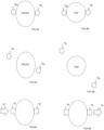
- a first set of different audio output channels 30 1 , 30 2 are rendered using different associated transducers 22 1 , 22 2 to provide sound to the right ear 202 R .
- a second set of different audio output channels 30 3 , 30 4 are rendered using different associated transducers 22 3 , 22 4 to provide sound to the left ear 202 L .
- the different audio output channels 30 1 , 30 2 of the first set are controlled to represent a first spatial audio object 70 R , 70 1 and the different audio output channels 30 3 , 30 4 of the second set are controlled to represent a second spatial audio object 70 L , 70 2 .
- Each set of audio output channels comprises a bone-conduction audio output channel and an air-conduction audio output channel.
- the first set of audio output channels provides stereo output for the right ear and the second set of audio output channels provides stereo output for the left ear.
- the first audio object 70 R is the right-ear stereo loudspeaker located adjacent the right-ear 202 R .
- the second audio object 70 L is the left-ear stereo loudspeaker located adjacent the left-ear 202 L .
- FIG 4A illustrates a front perspective and FIG 4B illustrates a top perspective.
- the first set of audio output channels provides binaural output for the right ear and the second set of audio output channels provides binaural output for the left ear.
- the combination of the first set of audio output channels and the second set of audio output channels locates a first spatial audio object 70, at a distance and bearing from the user 200.
- the combination of the first set of audio output channels and the second set of audio output channels locates a second spatial audio object 70 2 at a distance and bearing from the user 200.
- FIG 5A illustrates a front perspective
- FIG 5B illustrates a top perspective.
- the first spatial audio object 70 can be a virtual loudspeaker (sound source).
- the second spatial audio object 70 2 can be a virtual loudspeaker (sound source).
- the set of audio output channels may provide, mono, stereo or any other type of audio that can be used with the apparatus 10.
- the filter controller 40 of the apparatus 10 is configured to automatically change the cut-off frequencies of audio output channels 30 in dependence upon a dynamic assessment of parameters that relate to impairment of the audio output channels 30.
- the filter controller 40 is configured to automatically change the cut-off frequency of a lower frequency audio output channel 30 1 /30 3 for an ear to increase a bandwidth (increase the upper cut-off frequency f uco ) of that lower frequency audio output channel 30 1 /30 3 , in dependence upon impairment of the higher frequency audio output channels 30 2 /30 4 for the same ear.
- the filter controller 40 is configured to automatically change the cross-over frequency f xo between a lower frequency audio output channel 30 1 /30 3 and a higher frequency audio output channel 30 2 /30 4 for the same ear, in dependence upon impairment of the respective higher frequency audio output channel 30 2 /30 4 for the same ear.
- the impairment can, for example, be based on hearability.
- the automatic change in a cut-off frequency (or cross-over frequency) optimizes or improves hearability.
- an exterior noise 72 in the exterior environment 100 reduces hearability to the user 200 via an air-conduction audio output channel and causes an impairment to the user 200.
- the exterior noise can for example be wind, machinery or other noises.
- the impairment can be detected by using a sensor 50 (not illustrated) to sense the environment 100.
- a microphone can listen to sounds in the exterior environment 100 and an impairment can be detected when the energy density per Hz exceeds a threshold within a defined spectral range.
- an impairment can be detected when the exterior noise is a loud higher frequency noise, for example, such as wind.
- the apparatus 10 responds to detection of the impairment by automatically changing the cut-off (cross-over) frequency so that higher frequency audio signals are provided via the bone-conduction audio output channel rather than the air-conduction audio output channel.
- the threshold used to detect impairment can, for example, be based on one or more properties of the audio output channels 30 such as energy spectrum and/or audio content (e.g. speech, private,.).
- the apparatus 10 can be configured to automatically change the cut-off frequency of an audio output channel in dependence upon a dynamic assessment of one or more of: one or more properties of the audio output channels; audio content; and/or an environment of the user.
- the impairment can be detected by using a sensor 50 (not illustrated) to sense a nearby potential eavesdropper or to sense that the apparatus 10 is in a public environment 100 (rather than a private environment).
- the apparatus 10 responds to detection of the impairment by automatically changing the cut-off (cross-over) frequency so that higher frequency audio signals are provided via the bone-conduction audio output channel rather than the air-conduction audio output channel to improve privacy and reduce the likelihood of being overheard.
- the detection of such a privacy impairment can be activated when the audio signals rendered to the user comprise speech or other private content and/or when the energy spectrum of the audio signal exceeds a threshold value.
- the assessment of impairment is dynamic and can be based upon: one or more properties of the audio output channels 30 such as energy spectrum and/or audio content (e.g. speech, private,.%) and/or an environment 100 of the user 200.
- one or more properties of the audio output channels 30 such as energy spectrum and/or audio content (e.g. speech, private,.8) and/or an environment 100 of the user 200.
- the cut-off frequency of a first audio output channel 30 is automatically changed in dependence upon a dynamic assessment of content for rendering as private content and a local environment as a public environment. More information can be transferred to the less leaky channel. For example, by increasing the upper cut-off frequency for the bone conduction channel and the lower cut-off frequency for the air conduction channel.
- the cut-off frequency of a first audio output channel 30 is automatically changed in dependence upon a dynamic assessment of content for rendering as comprising speech and a local environment as a noisy environment.
- More information can be transferred to the less noisy channel. For example, by increasing the upper cut-off frequency for the bone conduction channel and optionally the lower cut-off frequency for air conduction channel.
- the cut-off frequency of a first audio output channel 30 is automatically changed in dependence upon a dynamic assessment of a local environment 100 as an environment subject to wind noise. More information can be transferred to the less noisy channel. For example, by increasing the upper cut-off frequency for the bone conduction channel and optionally the lower cut-off frequency for the air conduction channel.
- the cut-off frequency of a first audio output channel 30 is automatically changed in dependence upon a dynamic assessment of content for rendering as spatial audio content to be rendered from different directions and assessment of a local environment as a noisy environment in some but not all directions. More information can be transferred to the less noisy conduction channel. For example, by increasing the upper cut-off frequency (or cross-over frequency) for the bone-conduction channel(s) associated with the spatial audio channel with noise.
- the apparatus 10 can be configured to automatically change the cut-off frequency of an audio output channel in dependence upon a dynamic assessment of one or more of: sensor output; noise; content for rendering.
- FIG 7 illustrates an example of an apparatus 10 previously described, with both a bone-conduction transducer 22, and an air-conduction transducer 22 2 . Similar references are used for similar features.
- the apparatus 10 can be a headset for example as illustrated in FIG 10.
- a filtered part 4 1 of the audio signal 2 is routed to the bone-conduction transducer 22, and a differently filtered part 4 2 of the audio signal 2 is routed to the air-conduction transducer 22 2 .
- This can be done, for example, by applying a low-pass filter 24 LP to the audio signal 2 to produce the audio signal 4 1 going to the bone-conduction transducer 22, and by applying a high-pass filter 24 HP to the audio signal 2 to produce the audio signal 4 2 going to the air-conduction transducer 22 2 .
- Frequencies above a certain threshold are filtered from the audio signals 4 1 going to the bone-conduction transducer 22, and frequencies below a certain threshold (f lco ) are filtered from the audio signals 4 2 going into the air-conduction transducer 22 2 .
- the filters 24 LP , 24 HP can be designed so that frequencies below a certain threshold (the cross-over frequency f xo ) are filtered from the audio signals 4 2 going into the air-conduction transducer 22 2 and frequencies above this same threshold f xo are filtered from the audio signal 4 1 going to the bone-conduction transducer 22 1 .
- the apparatus 10 can be used in different environments 100 and the audio signals 2 can be used to render various kinds of different content.
- the apparatus 10 does not use a fixed cut-off frequency (or cross-over frequency), and therefore mitigates a sub-optimal user experience.
- the cut-off/cross-over frequency can be set low such that a user 200, listening to audio in a quiet environment 100, hears high bandwidth audio via the air-conduction audio output channel 30 2 and can be set higher in a noisy environment 100 (e.g. wind noise, construction noise, engine noise...) such that a user 200 listening hears a higher bandwidth via the bone-conduction audio output channel 30 1 .
- a noisy environment 100 e.g. wind noise, construction noise, engine noise
- the adaptive cut-off/cross-over frequency can be used for:
- An optimal cut-off/cross-over frequency can be selected based on the user's environment 100 and/or the content (or content type) of the audio signals 2 rendered to the user 200.
- the cut-off/cross-over frequency can be determined based on the type of content rendered and/or the environment 100.
- the cut-off/cross-over frequency can be applied in a direction specific manner.
- the cut-off/cross-over frequency for a particular direction can be dependent upon the environment 100 (e.g. noise) in that direction and/or the content (or content type) rendered to the user 200 from that direction based on the audio signals 2.
- the directionality of the cut-off/cross-over frequency can be dependent on which audio sources are heard from which direction and from which direction environmental sounds (noise) is heard by the user.
- the directionality can be taken into account by applying:
- Adaptation may be done based on both, the spatial content directions and direction of the potentially disturbing environmental noises
- cut-off/cross-over frequencies for different parts 12 L , 12 R can be set separately.
- optimal cut-off/cross-over frequencies for different environments 100 and/or content (or content type) of the audio signals 2 rendered to the user 200 are predetermined and stored in a database in a memory.
- the cut-off/cross-over frequency is read from the database based on combinations of parameters representing different combinations of environments 100 and/or content of the audio signals 2.
- the automatic changing of a cut-off/cross-over frequency can therefore be based on pre-stored characteristics. Pre-stored characteristics can be combined by maximizing the cross-over frequency.
- Environment detection can use environmental values 52 from various sensors 50 such as, for example, noise sensors 50B.
- the sensors 50 can use sensing hardware such as, for example, a microphone 53, gyroscope, accelerometer, proximity detector, a location detector etc.
- noise sensing 50B e.g. wind noise detection
- a microphone or microphones 53 One example of environment detection is noise sensing 50B (e.g. wind noise detection) using a microphone or microphones 53.
- Content detection can use environmental values 52 from various sensors 50 such as speech sensors 50A.
- the sensors 50 can process data, for example, the audio signals 2 or metadata associated with the audio signals 2.
- Content type determination can use the metadata associated with the audio signals 2 (if available) or can process the audio signals 2 to determine content or content type algorithmically. For example, speech or music can be disambiguated.
- the content type can be determined to be stereophonic or binaural spatial audio.
- content (or content type) of the audio signals 2 rendered to the user 200 is spatial audio content.
- the user 200 is listening to spatial audio content using the head-mounted audio output apparatus 10.
- the spatial audio content comprises audio sources/objects that have been placed in different directions around the user 200.
- the user 200 hears music content from the left and speech content from the right (a phone call with a friend).
- the cut-off/cross-over frequency is set separately for the different content types. That is, the cut-off/cross-over frequency for the music content is set according to what is optimal for music listening and the cross-over frequency for the speech is set according to what is optimal for the speech signal.
- the user is in a noisy environment 100.
- the noise source is to the right of the user 200 and impacts mainly how the user 200 hears speech content.
- the noise may be, for example, wind noise that is affecting only the right air-conduction transducer 22 2 (see FIG 3 ).
- the cut-off/cross-over frequency is adjusted (made higher) due to the noise only for the right transducers 22 1 , 22 2 (see FIG 3 ).
- the cut-off/cross-over frequency is not adjusted for the left transducers 22 3 , 22 4 (see FIG 3 ).
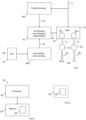
- FIG 7 shows a block diagram for an example use case.
- the cut-off/cross-over frequency is adjusted based on the presence of speech content in the content of the audio signals 2 rendered to the user 200.
- Content sensing block 50A implements speech sensing and detection using speech detection methods.
- One example is to extract features, such as mel-frequency cepstral coefficients (MFCCs), from the content of the audio signal 2 and feed these into a classifier (Gaussian Mixture Model (GMM) classifier, for example) for classification to speech and non-speech parts.
- GMM Garnier Mixture Model
- the GMM classifier is prior-trained on a large database of speech/non-speech data.
- Neural networks could also be used to build a classifier.
- the cut-off/cross-over frequency determination block 40 looks at the classifier output and sets the cut-off frequency (cross-over frequency in this example) to the value that is determined in a stored database.
- the cut-off frequencies may be set to 150Hz for no speech and 2kHz for speech.
- FIG 7 shows a block diagram for another example use case.
- the cut-off/cross-over frequency is adjusted based on the presence of wind noise in the environment 100.
- the environment noise sensing block 50B processes sound recorded by an environmental microphone 53 and determines in which (if any) parts of the frequency spectrum wind noise is present. This may be done by comparing, frequency band-wise, level differences in microphone signals captured by spatially separated the microphones 53, for example, microphones 53 on the different left and right parts 12 L , 12 R . If the level difference in a frequency band is over a threshold e.g. 6dB, this band is considered to contain wind noise.
- the cut-off/cross-over frequency is set by the cut-off/cross-over frequency determination block 40 (this corresponds to the filter controller 40) so that the highest frequency band that contains wind noise is 'covered' by the bone-conduction channel. For example, if a frequency band, let's say 500Hz-1kHz is the highest which contains wind noise, the cut-off/cross-over frequency is increased to 1kHz. If no wind-noise is present the cut-off frequency is maintained at 150Hz.
- Figure 7 shows a block diagram for another example use case where the cut-off/cross-over frequency is adjusted based on both the presence of speech content in the content of the audio signals 2 rendered to the user 200 and also the presence of wind noise in the environment 100.
- the cut-off/cross-over frequency is set to the highest one of the two values determined by the two separate use cases described above for FIG 7 . That is, both the wind-noise dependent cut-off/cross-over frequency and the speech content dependent cut-off/cross-over frequency are determined as in the previous examples at cut-off/cross-over frequency determination block 40 and the highest one of these is used as the cut-off/cross-over frequency of the filter.
- the apparatus 10 comprises means for: adaptively filtering audio output channels 30 for rendering separately via a head-positioned audio output device comprising automatically changing a cut-off frequency of at least a first filter 24 of a first audio output channel 30.
- Fig 8 illustrates an example of a controller 80.
- Implementation of a controller 80 may be as controller circuitry.
- the controller 80 may be implemented in hardware alone, have certain aspects in software including firmware alone or can be a combination of hardware and software (including firmware).
- the controller 80 may be implemented using instructions that enable hardware functionality, for example, by using executable instructions of a computer program 86 in a general-purpose or special-purpose processor 82 that may be stored on a computer readable storage medium (disk, memory etc) to be executed by such a processor 82.
- a general-purpose or special-purpose processor 82 may be stored on a computer readable storage medium (disk, memory etc) to be executed by such a processor 82.
- the processor 82 is configured to read from and write to the memory 84.
- the processor 82 may also comprise an output interface via which data and/or commands are output by the processor 82 and an input interface via which data and/or commands are input to the processor 82.
- the memory 84 stores a computer program 86 comprising computer program instructions (computer program code) that controls the operation of the apparatus 10 when loaded into the processor 82.
- the computer program instructions, of the computer program 86 provide the logic and routines that enables the apparatus to perform the methods illustrated and described.
- the processor 82 by reading the memory 84 is able to load and execute the computer program 86.
- the apparatus 10 therefore comprises:
- the computer program 86 may arrive at the apparatus 10 via any suitable delivery mechanism 88.
- the delivery mechanism 88 may be, for example, a machine readable medium, a computer-readable medium, a non-transitory computer-readable storage medium, a computer program product, a memory device, a record medium such as a Compact Disc Read-Only Memory (CD-ROM) or a Digital Versatile Disc (DVD) or a solid state memory, an article of manufacture that comprises or tangibly embodies the computer program 86.
- the delivery mechanism may be a signal configured to reliably transfer the computer program 86.
- the apparatus 10 may propagate or transmit the computer program 86 as a computer data signal.
- the computer program 86 that when run on at least one processor of an audio output apparatus 10 comprising a hybrid audio system 20 comprising multiple transducers 22 configured to render sound for a user 200 of the apparatus 10 into different audio output channels 30, causes an automatic change of a cut-off frequency of one or more audio output channels 30 in dependence upon the one or more transducers 22 associated with the respective one or more audio output channels 30.
- the computer program instructions may be comprised in a computer program, a non-transitory computer readable medium, a computer program product, a machine readable medium. In some but not necessarily all examples, the computer program instructions may be distributed over more than one computer program.
- memory 84 is illustrated as a single component/circuitry it may be implemented as one or more separate components/circuitry some or all of which may be integrated/removable and/or may provide permanent/semi-permanent/ dynamic/cached storage.
- processor 82 is illustrated as a single component/circuitry it may be implemented as one or more separate components/circuitry some or all of which may be integrated/removable.
- the processor 82 may be a single core or multi-core processor.
- references to 'computer-readable storage medium', 'computer program product', 'tangibly embodied computer program' etc. or a 'controller', 'computer', 'processor' etc. should be understood to encompass not only computers having different architectures such as single /multi- processor architectures and sequential (Von Neumann)/parallel architectures but also specialized circuits such as field-programmable gate arrays (FPGA), application specific circuits (ASIC), signal processing devices and other processing circuitry.
- References to computer program, instructions, code etc. should be understood to encompass software for a programmable processor or firmware such as, for example, the programmable content of a hardware device whether instructions for a processor, or configuration settings for a fixed-function device, gate array or programmable logic device etc.
- circuitry may refer to one or more or all of the following:
- circuitry also covers an implementation of merely a hardware circuit or processor and its (or their) accompanying software and/or firmware.
- circuitry also covers, for example and if applicable to the particular claim element, a baseband integrated circuit for a mobile device or a similar integrated circuit in a server, a cellular network device, or other computing or network device.
- the blocks illustrated in the FIGs may represent steps in a method and/or sections of code in the computer program 86.
- the illustration of a particular order to the blocks does not necessarily imply that there is a required or preferred order for the blocks and the order and arrangement of the block may be varied. Furthermore, it may be possible for some blocks to be omitted.
- module' refers to a unit or apparatus that excludes certain parts/components that would be added by an end manufacturer or a user.
- the apparatus 10 can be a module.
- a property of the instance can be a property of only that instance or a property of the class or a property of a sub-class of the class that includes some but not all of the instances in the class. It is therefore implicitly disclosed that a feature described with reference to one example but not with reference to another example, can where possible be used in that other example as part of a working combination but does not necessarily have to be used in that other example.
- 'a' or 'the' is used in this document with an inclusive not an exclusive meaning. That is any reference to X comprising a/the Y indicates that X may comprise only one Y or may comprise more than one Y unless the context clearly indicates the contrary. If it is intended to use 'a' or 'the' with an exclusive meaning then it will be made clear in the context. In some circumstances the use of 'at least one' or ⁇ one or more' may be used to emphasis an inclusive meaning but the absence of these terms should not be taken to infer any exclusive meaning.
Landscapes
- Physics & Mathematics (AREA)
- Engineering & Computer Science (AREA)
- Acoustics & Sound (AREA)
- Signal Processing (AREA)
- Health & Medical Sciences (AREA)
- General Health & Medical Sciences (AREA)
- Otolaryngology (AREA)
- Circuit For Audible Band Transducer (AREA)
Claims (12)
- Kopfmontierte Audioausgabevorrichtung (10), die Folgendes umfasst:mindestens ein hybrides Audiosystem (20), das mehrere Wandler (22) umfasst, wobei das hybride Audiosystem (20) dazu ausgelegt ist, einen Klang für einen Benutzer (200) der kopfmontierten Audioausgabevorrichtung (10) unter Verwendung von verschiedenen verknüpften Wandlern der mehreren Wandler (22) in verschiedene Audioausgabekanäle (30) zu rendern, wobei das hybride Audiosystem dazu ausgelegt ist, einen Klang für den Benutzer der Vorrichtung unter Verwendung eines zugehörigen Knochenleitungswandlers in einen Knochenleitungsaudioausgabekanal und unter Verwendung eines zugehörigen Luftleitungswandlers in einen Luftleitungsaudioausgabekanal zu rendern;Mittel zum Ändern einer Grenzfrequenz von mindestens einem ersten der Audioausgabekanäle (30) in Abhängigkeit vom Wandler, der mit dem ersten der Audioausgabekanäle verknüpft ist, wobei der erste der Audioausgabekanäle der Knochenleitungsaudioausgabekanal ist, undwobei die Mittel zum Ändern der Grenzfrequenz von mindestens dem ersten der Audioausgabekanäle zu Folgendem ausgelegt sind:automatisches Ändern einer Übergangsfrequenz des ersten der Audioausgabekanäle und eines zweiten der Audioausgabekanäle; undautomatisches Ändern der Grenzfrequenz des ersten der Audioausgabekanäle in Abhängigkeit von einer Spektralanalyse von externen Geräuschen.
- Kopfmontierte Audioausgabevorrichtung nach Anspruch 1, wobei die Mittel zum Ändern einer Grenzfrequenz von mindestens dem ersten der Audioausgabekanäle dazu ausgelegt sind, die Grenzfrequenz des ersten der Audioausgabekanäle in Abhängigkeit von mindestens einem erfassten Umgebungswert in einer Position der kopfmontierten Audioausgabevorrichtung zu ändern.
- Kopfmontierte Audioausgabevorrichtung nach einem der vorhergehenden Ansprüche, wobei die Mittel zum Ändern der Grenzfrequenz von mindestens dem ersten der Audioausgabekanäle dazu ausgelegt sind, die Übergangsfrequenz zwischen einem Audioausgabekanal einer niedrigeren Frequenz und einem Audioausgabekanal einer höheren Frequenz zu erhöhen, derart, dass eine Bandbreite des Audioausgabekanals der niedrigeren Frequenz zunimmt und eine Bandbreite des Audioausgabekanals der höheren Frequenz abnimmt.
- Kopfmontierte Audioausgabevorrichtung nach einem der vorhergehenden Ansprüche, wobei das hybride Audiosystem dazu ausgelegt ist, einen Klang für ein linkes Ohr des Benutzers unter Verwendung eines verknüpften ersten Wandlers in einen ersten Audioausgabekanal unter Verwendung eines verknüpften zweiten Wandlers in einen zweiten Audioausgabekanal zu rendern, und dazu ausgelegt, einen Klang für ein rechtes Ohr des Benutzers unter Verwendung eines zugehörigen dritten Wandlers in einen dritten Audioausgabekanal unter Verwendung eines verknüpften vierten Wandlers in einen vierten Audioausgabekanal zu rendern.
- Kopfmontierte Audioausgabevorrichtung nach Anspruch 4, wobei ein erster Satz von verschiedenen Audioausgabekanälen, die den ersten Audioausgabekanal und den zweiten Audioausgabekanal umfassen, und ein zweiter Satz von verschiedenen Audioausgabekanälen, die den dritten Audioausgabekanal und den vierten Audioausgabekanal umfassen, zum Rendern von einem oder mehreren Audioobjekten gesteuert werden.
- Kopfmontierte Audioausgabevorrichtung nach einem der vorhergehenden Ansprüche, wobei die Mittel zum Ändern einer Grenzfrequenz von mindestens dem ersten der Audioausgabekanäle dazu ausgelegt sind, die Grenzfrequenz des ersten der Audioausgabekanäle in Abhängigkeit von einer dynamischen Beurteilung von einem oder mehreren von Folgendem automatisch zu ändern:einer oder mehreren Eigenschaften der Audioausgabekanäle;einem Audioinhalt; und/odereiner Umgebung des Benutzers.
- Kopfmontierte Audioausgabevorrichtung nach Anspruch 6, wobei die Mittel zum Ändern einer Grenzfrequenz von mindestens dem ersten der Audioausgabekanäle dazu ausgelegt sind, die Grenzfrequenz des ersten der Audioausgabekanäle automatisch zu ändern, um eine Bandbreite des ersten der Audioausgabekanäle in Abhängigkeit von einer Beeinträchtigung eines zweiten der Audioausgabekanäle zu erhöhen.
- Kopfmontierte Audioausgabevorrichtung nach einem der vorhergehenden Ansprüche, wobei die Mittel zum Ändern einer Grenzfrequenz von mindestens dem ersten der Audioausgabekanäle dazu ausgelegt sind, die Grenzfrequenz des ersten der Audioausgabekanäle zum Optimieren einer Hörbarkeit automatisch zu ändern.
- Kopfmontierte Audioausgabevorrichtung nach einem der vorhergehenden Ansprüche, wobei die Mittel zum Ändern einer Grenzfrequenz von mindestens dem ersten der Audioausgabekanäle dazu ausgelegt sind, die Grenzfrequenz des ersten der Audioausgabekanäle in Abhängigkeit von einer dynamischen Beurteilung von einem oder mehreren von Sensorausgabe; Geräuschen; zu rendernden Inhalt automatisch zu ändern.
- Kopfmontierte Audioausgabevorrichtung nach einem der vorhergehenden Ansprüche, wobei die Mittel zum Ändern einer Grenzfrequenz von mindestens dem ersten der Audioausgabekanäle dazu ausgelegt sind, die Grenzfrequenz von dem ersten der Audioausgabekanäle in Abhängigkeit von mindestens einem von Folgendem automatisch zu ändern:(i) einer dynamischen Beurteilung eines zu rendernden Inhalts als einen privaten Inhalt und einer lokalen Umgebung als eine öffentliche Umgebung;(ii) einer dynamischen Beurteilung eines zu rendernden Inhalts, der Sprache umfasst, und einer lokalen Umgebung als eine laute Umgebung;(iiii) einer dynamischen Beurteilung einer lokalen Umgebung als eine Umgebung, die Windgeräuschen unterliegt; oder(iv) einer dynamischen Beurteilung eines zu rendernden Inhalts als zu rendernden räumlichen Audioinhalt aus verschiedenen Richtungen und Beurteilung einer lokalen Umgebung als eine laute Umgebung in einigen, aber nicht in allen Richtungen.
- Computerprogramm (86), das, wenn es auf mindestens einem Prozessor (82) einer kopfmontierten Audioausgabevorrichtung läuft, die ein hybrides Audiosystem (20) umfasst, das mehrere Wandler (22) umfasst, die dazu ausgelegt sind, einen Klang für einen Benutzer (200) der kopfmontierten Audioausgabevorrichtung in verschiedene Audioausgabekanäle (30) zu rendern, Folgendes veranlasst:eine Änderung einer Grenzfrequenz von einem oder mehreren Audioausgabekanälen (30) in Abhängigkeit von dem einen oder den mehreren Wandlern (22), die mit dem einen oder den mehreren jeweiligen Audioausgabekanälen (30) verknüpft sind, wobei eine automatische Änderung der Grenzfrequenz eines ersten des einen oder der mehreren Audioausgabekanäle in Abhängigkeit von einer Spektralanalyse von externen Geräuschen erfolgt; undeine automatische Änderung einer Übergangsfrequenz des ersten des einen oder der mehreren Audioausgabekanäle und eines zweiten des einen oder der mehreren Audioausgabekanäle,wobei das hybride Audiosystem dazu ausgelegt ist, einen Klang für den Benutzer der Vorrichtung unter Verwendung eines zugehörigen Knochenleitungswandlers in einen Knochenleitungsaudioausgabekanal und unter Verwendung eines zugehörigen Luftleitungswandlers in einen Luftleitungsaudioausgabekanal zu rendern, wobei der erste des einen oder der mehreren Audioausgabekanäle der Knochenleitungsaudioausgabekanal ist.
- Verfahren, das Folgendes umfasstVerwenden eines hybriden Audiosystems (20) einer kopfmontierten Audioausgabevorrichtung, und das mehrere Wandler (22) umfasst, um einen Klang für einen Benutzer (200) in verschiedene Audioausgabekanäle (30) zu rendern, wobei ein erster der Audioausgabekanäle (301), der mit einem ersten Wandler (221) verknüpft ist, eine erste Grenzfrequenz (fuco) aufweist, und wobei ein zweiter der Audioausgabekanäle (302), der mit einem zweiten Wandler (222) verknüpft ist, der sich vom ersten Wandler (221) unterscheidet, eine zweite Grenzfrequenz (flco) aufweist, wobei das hybride Audiosystem dazu ausgelegt ist, einen Klang für den Benutzer unter Verwendung eines zugehörigen Knochenleitungswandlers in einen Knochenleitungsaudioausgabekanal und unter Verwendung eines zugehörigen Luftleitungswandlers in einen Luftleitungsaudioausgabekanal zu rendern, wobei der erste der Audioausgabekanäle der Knochenleitungsaudioausgabekanal ist;automatisches Ändern der ersten Grenzfrequenz (fuco) in eine andere erste Grenzfrequenz (f'uco) in Abhängigkeit von einer Spektralanalyse von externen Geräuschen und Ändern der zweiten Grenzfrequenz (flco) in eine andere zweite Grenzfrequenz (f'lco), wobei sich die Änderung der ersten Grenzfrequenz (fuco) in die andere erste Grenzfrequenz (f'uco) von einer Änderung der zweiten Grenzfrequenz (flco) in die andere zweite Grenzfrequenz (f'lco) unterscheidet;automatisches Ändern einer Übergangsfrequenz des ersten der Audioausgabekanäle und des zweiten der Audioausgabekanäle; undVerwenden des hybriden Audiosystems (20), das die mehreren Wandler (22) umfasst, um einen Klang für den Benutzer (200) in verschiedene Audioausgabekanäle (30) zu rendern, wobei der erste der Audioausgabekanäle (301), der mit dem ersten Wandler (221) verknüpft ist, die andere erste Grenzfrequenz (f'uco) aufweist, und wobei der zweite der Audioausgabekanäle (302), der mit dem zweiten Wandler (222) verknüpft ist, der sich vom ersten Wandler (221) unterscheidet, die andere zweite Grenzfrequenz (f'lco) aufweist.
Priority Applications (2)
| Application Number | Priority Date | Filing Date | Title |
|---|---|---|---|
| EP20209790.3A EP4007299B1 (de) | 2020-11-25 | 2020-11-25 | Audioausgabe mit mehreren unterschiedlichen wandlern |
| US17/521,507 US11877133B2 (en) | 2020-11-25 | 2021-11-08 | Audio output using multiple different transducers |
Applications Claiming Priority (1)
| Application Number | Priority Date | Filing Date | Title |
|---|---|---|---|
| EP20209790.3A EP4007299B1 (de) | 2020-11-25 | 2020-11-25 | Audioausgabe mit mehreren unterschiedlichen wandlern |
Publications (2)
| Publication Number | Publication Date |
|---|---|
| EP4007299A1 EP4007299A1 (de) | 2022-06-01 |
| EP4007299B1 true EP4007299B1 (de) | 2024-12-11 |
Family
ID=73597930
Family Applications (1)
| Application Number | Title | Priority Date | Filing Date |
|---|---|---|---|
| EP20209790.3A Active EP4007299B1 (de) | 2020-11-25 | 2020-11-25 | Audioausgabe mit mehreren unterschiedlichen wandlern |
Country Status (2)
| Country | Link |
|---|---|
| US (1) | US11877133B2 (de) |
| EP (1) | EP4007299B1 (de) |
Families Citing this family (3)
| Publication number | Priority date | Publication date | Assignee | Title |
|---|---|---|---|---|
| US12300260B2 (en) * | 2022-02-08 | 2025-05-13 | Analog Devices International Unlimited Company | Audio signal processing method and system for noise mitigation of a voice signal measured by air and bone conduction sensors |
| WO2024097651A1 (en) * | 2022-10-31 | 2024-05-10 | Aman Christopher | Method and apparatus for mitigating phase interference or cancellation by aligning waveforms to 3rd harmonics |
| US20240260857A1 (en) * | 2023-02-07 | 2024-08-08 | Creare Llc | Systems and methods for wirelessly connected audiometer headsets, interface devices, and administrator devices |
Family Cites Families (11)
| Publication number | Priority date | Publication date | Assignee | Title |
|---|---|---|---|---|
| DE2415816C3 (de) * | 1974-04-01 | 1981-10-29 | Arndt 7500 Karlsruhe Klingenberg | Verfahren zur Begrenzung der maximalen Belastung von elektroakustischen Wandlersystemen |
| JPH0724440B2 (ja) * | 1986-08-19 | 1995-03-15 | キヤノン株式会社 | オ−デイオ信号伝送システム |
| GB2445984B (en) * | 2007-01-25 | 2011-12-07 | Sonaptic Ltd | Ambient noise reduction |
| RU2545383C2 (ru) * | 2009-04-21 | 2015-03-27 | Конинклейке Филипс Электроникс Н.В. | Возбуждение многоканальных громкоговорителей |
| US9020168B2 (en) * | 2011-08-30 | 2015-04-28 | Nokia Corporation | Apparatus and method for audio delivery with different sound conduction transducers |
| DE102013221754A1 (de) * | 2013-10-25 | 2015-04-30 | Kaetel Systems Gmbh | Kopfhörer und verfahren zum herstellen eines kopfhörers |
| US9930436B2 (en) | 2014-06-26 | 2018-03-27 | Temco Japan Co., Ltd. | Bone conduction speaker |
| US9432761B2 (en) * | 2014-10-08 | 2016-08-30 | Nxp B.V. | Signal processor |
| US10547930B1 (en) | 2016-12-20 | 2020-01-28 | Amazon Technologies, Inc. | Dynamic range management of bone conduction speaker output |
| US10728649B1 (en) | 2017-05-26 | 2020-07-28 | Apple Inc. | Multipath audio stimulation using audio compressors |
| DE102017126432A1 (de) * | 2017-11-10 | 2019-05-16 | Sennheiser Electronic Gmbh & Co. Kg | Hörer |
-
2020
- 2020-11-25 EP EP20209790.3A patent/EP4007299B1/de active Active
-
2021
- 2021-11-08 US US17/521,507 patent/US11877133B2/en active Active
Also Published As
| Publication number | Publication date |
|---|---|
| US20220167087A1 (en) | 2022-05-26 |
| US11877133B2 (en) | 2024-01-16 |
| EP4007299A1 (de) | 2022-06-01 |
Similar Documents
| Publication | Publication Date | Title |
|---|---|---|
| KR102354215B1 (ko) | 콘텍스트에 기초한 주변 사운드 향상 및 음향 노이즈 소거 | |
| CN113905320B (zh) | 为考虑语音检测而调节声音回放的方法和系统 | |
| US11902772B1 (en) | Own voice reinforcement using extra-aural speakers | |
| CN109310525B (zh) | 媒体补偿通过和模式切换 | |
| US12407972B2 (en) | Auditory augmented reality using selective noise cancellation | |
| EP2953383B1 (de) | Signalverarbeitungsschaltung | |
| US11877133B2 (en) | Audio output using multiple different transducers | |
| TWI843823B (zh) | 用於處理多個音訊空間之間的音訊之系統和方法 | |
| EP3873105B1 (de) | System und verfahren zur auswertung und einstellung von audiosignalen | |
| EP3433857B1 (de) | Verfahren und vorrichtung zur geräuschreduktion | |
| KR20100119890A (ko) | 오디오 디바이스 및 이에 대한 동작 방법 | |
| US12175159B1 (en) | Privacy with extra-aural speakers | |
| US20220122630A1 (en) | Real-time augmented hearing platform | |
| US20250372119A1 (en) | Capturing and processing audio signals | |
| WO2024238643A1 (en) | Audio processing using hearing loss data | |
| US12363492B1 (en) | Spatial audio using near-field and far-field rendering | |
| CN116266892A (zh) | 用于抑制风噪声的系统、方法及听力设备 | |
| US20240223970A1 (en) | Wearable hearing assist device with sound pressure level shifting | |
| US12335689B2 (en) | Computing devices and methods for processing audio content for transmission to a hearing device | |
| US20250113154A1 (en) | Spatial Audio Conversation Channel | |
| CN121792898A (zh) | 增益调整方法、装置、耳机及存储介质 | |
| HK40000315B (zh) | 媒体补偿通过和模式切换 |
Legal Events
| Date | Code | Title | Description |
|---|---|---|---|
| PUAI | Public reference made under article 153(3) epc to a published international application that has entered the european phase |
Free format text: ORIGINAL CODE: 0009012 |
|
| STAA | Information on the status of an ep patent application or granted ep patent |
Free format text: STATUS: THE APPLICATION HAS BEEN PUBLISHED |
|
| AK | Designated contracting states |
Kind code of ref document: A1 Designated state(s): AL AT BE BG CH CY CZ DE DK EE ES FI FR GB GR HR HU IE IS IT LI LT LU LV MC MK MT NL NO PL PT RO RS SE SI SK SM TR |
|
| STAA | Information on the status of an ep patent application or granted ep patent |
Free format text: STATUS: REQUEST FOR EXAMINATION WAS MADE |
|
| 17P | Request for examination filed |
Effective date: 20221201 |
|
| RBV | Designated contracting states (corrected) |
Designated state(s): AL AT BE BG CH CY CZ DE DK EE ES FI FR GB GR HR HU IE IS IT LI LT LU LV MC MK MT NL NO PL PT RO RS SE SI SK SM TR |
|
| GRAP | Despatch of communication of intention to grant a patent |
Free format text: ORIGINAL CODE: EPIDOSNIGR1 |
|
| STAA | Information on the status of an ep patent application or granted ep patent |
Free format text: STATUS: GRANT OF PATENT IS INTENDED |
|
| INTG | Intention to grant announced |
Effective date: 20240327 |
|
| GRAJ | Information related to disapproval of communication of intention to grant by the applicant or resumption of examination proceedings by the epo deleted |
Free format text: ORIGINAL CODE: EPIDOSDIGR1 |
|
| STAA | Information on the status of an ep patent application or granted ep patent |
Free format text: STATUS: REQUEST FOR EXAMINATION WAS MADE |
|
| GRAP | Despatch of communication of intention to grant a patent |
Free format text: ORIGINAL CODE: EPIDOSNIGR1 |
|
| STAA | Information on the status of an ep patent application or granted ep patent |
Free format text: STATUS: GRANT OF PATENT IS INTENDED |
|
| INTC | Intention to grant announced (deleted) | ||
| INTG | Intention to grant announced |
Effective date: 20240705 |
|
| GRAS | Grant fee paid |
Free format text: ORIGINAL CODE: EPIDOSNIGR3 |
|
| GRAA | (expected) grant |
Free format text: ORIGINAL CODE: 0009210 |
|
| STAA | Information on the status of an ep patent application or granted ep patent |
Free format text: STATUS: THE PATENT HAS BEEN GRANTED |
|
| AK | Designated contracting states |
Kind code of ref document: B1 Designated state(s): AL AT BE BG CH CY CZ DE DK EE ES FI FR GB GR HR HU IE IS IT LI LT LU LV MC MK MT NL NO PL PT RO RS SE SI SK SM TR |
|
| REG | Reference to a national code |
Ref country code: GB Ref legal event code: FG4D |
|
| REG | Reference to a national code |
Ref country code: CH Ref legal event code: EP |
|
| REG | Reference to a national code |
Ref country code: IE Ref legal event code: FG4D |
|
| REG | Reference to a national code |
Ref country code: DE Ref legal event code: R096 Ref document number: 602020042893 Country of ref document: DE |
|
| REG | Reference to a national code |
Ref country code: LT Ref legal event code: MG9D |
|
| PG25 | Lapsed in a contracting state [announced via postgrant information from national office to epo] |
Ref country code: HR Free format text: LAPSE BECAUSE OF FAILURE TO SUBMIT A TRANSLATION OF THE DESCRIPTION OR TO PAY THE FEE WITHIN THE PRESCRIBED TIME-LIMIT Effective date: 20241211 |
|
| PG25 | Lapsed in a contracting state [announced via postgrant information from national office to epo] |
Ref country code: FI Free format text: LAPSE BECAUSE OF FAILURE TO SUBMIT A TRANSLATION OF THE DESCRIPTION OR TO PAY THE FEE WITHIN THE PRESCRIBED TIME-LIMIT Effective date: 20241211 |
|
| PG25 | Lapsed in a contracting state [announced via postgrant information from national office to epo] |
Ref country code: BG Free format text: LAPSE BECAUSE OF FAILURE TO SUBMIT A TRANSLATION OF THE DESCRIPTION OR TO PAY THE FEE WITHIN THE PRESCRIBED TIME-LIMIT Effective date: 20241211 |
|
| REG | Reference to a national code |
Ref country code: NL Ref legal event code: MP Effective date: 20241211 |
|
| PG25 | Lapsed in a contracting state [announced via postgrant information from national office to epo] |
Ref country code: ES Free format text: LAPSE BECAUSE OF FAILURE TO SUBMIT A TRANSLATION OF THE DESCRIPTION OR TO PAY THE FEE WITHIN THE PRESCRIBED TIME-LIMIT Effective date: 20241211 |
|
| PG25 | Lapsed in a contracting state [announced via postgrant information from national office to epo] |
Ref country code: NO Free format text: LAPSE BECAUSE OF FAILURE TO SUBMIT A TRANSLATION OF THE DESCRIPTION OR TO PAY THE FEE WITHIN THE PRESCRIBED TIME-LIMIT Effective date: 20250311 |
|
| PG25 | Lapsed in a contracting state [announced via postgrant information from national office to epo] |
Ref country code: LV Free format text: LAPSE BECAUSE OF FAILURE TO SUBMIT A TRANSLATION OF THE DESCRIPTION OR TO PAY THE FEE WITHIN THE PRESCRIBED TIME-LIMIT Effective date: 20241211 Ref country code: GR Free format text: LAPSE BECAUSE OF FAILURE TO SUBMIT A TRANSLATION OF THE DESCRIPTION OR TO PAY THE FEE WITHIN THE PRESCRIBED TIME-LIMIT Effective date: 20250312 |
|
| PG25 | Lapsed in a contracting state [announced via postgrant information from national office to epo] |
Ref country code: RS Free format text: LAPSE BECAUSE OF FAILURE TO SUBMIT A TRANSLATION OF THE DESCRIPTION OR TO PAY THE FEE WITHIN THE PRESCRIBED TIME-LIMIT Effective date: 20250311 |
|
| PG25 | Lapsed in a contracting state [announced via postgrant information from national office to epo] |
Ref country code: NL Free format text: LAPSE BECAUSE OF FAILURE TO SUBMIT A TRANSLATION OF THE DESCRIPTION OR TO PAY THE FEE WITHIN THE PRESCRIBED TIME-LIMIT Effective date: 20241211 |
|
| REG | Reference to a national code |
Ref country code: AT Ref legal event code: MK05 Ref document number: 1751311 Country of ref document: AT Kind code of ref document: T Effective date: 20241211 |
|
| PG25 | Lapsed in a contracting state [announced via postgrant information from national office to epo] |
Ref country code: SM Free format text: LAPSE BECAUSE OF FAILURE TO SUBMIT A TRANSLATION OF THE DESCRIPTION OR TO PAY THE FEE WITHIN THE PRESCRIBED TIME-LIMIT Effective date: 20241211 |
|
| PG25 | Lapsed in a contracting state [announced via postgrant information from national office to epo] |
Ref country code: PL Free format text: LAPSE BECAUSE OF FAILURE TO SUBMIT A TRANSLATION OF THE DESCRIPTION OR TO PAY THE FEE WITHIN THE PRESCRIBED TIME-LIMIT Effective date: 20241211 |
|
| PG25 | Lapsed in a contracting state [announced via postgrant information from national office to epo] |
Ref country code: IS Free format text: LAPSE BECAUSE OF FAILURE TO SUBMIT A TRANSLATION OF THE DESCRIPTION OR TO PAY THE FEE WITHIN THE PRESCRIBED TIME-LIMIT Effective date: 20250411 |
|
| PG25 | Lapsed in a contracting state [announced via postgrant information from national office to epo] |
Ref country code: PT Free format text: LAPSE BECAUSE OF FAILURE TO SUBMIT A TRANSLATION OF THE DESCRIPTION OR TO PAY THE FEE WITHIN THE PRESCRIBED TIME-LIMIT Effective date: 20250411 |
|
| PG25 | Lapsed in a contracting state [announced via postgrant information from national office to epo] |
Ref country code: EE Free format text: LAPSE BECAUSE OF FAILURE TO SUBMIT A TRANSLATION OF THE DESCRIPTION OR TO PAY THE FEE WITHIN THE PRESCRIBED TIME-LIMIT Effective date: 20241211 |
|
| PG25 | Lapsed in a contracting state [announced via postgrant information from national office to epo] |
Ref country code: RO Free format text: LAPSE BECAUSE OF FAILURE TO SUBMIT A TRANSLATION OF THE DESCRIPTION OR TO PAY THE FEE WITHIN THE PRESCRIBED TIME-LIMIT Effective date: 20241211 Ref country code: AT Free format text: LAPSE BECAUSE OF FAILURE TO SUBMIT A TRANSLATION OF THE DESCRIPTION OR TO PAY THE FEE WITHIN THE PRESCRIBED TIME-LIMIT Effective date: 20241211 |
|
| PG25 | Lapsed in a contracting state [announced via postgrant information from national office to epo] |
Ref country code: SK Free format text: LAPSE BECAUSE OF FAILURE TO SUBMIT A TRANSLATION OF THE DESCRIPTION OR TO PAY THE FEE WITHIN THE PRESCRIBED TIME-LIMIT Effective date: 20241211 |
|
| PG25 | Lapsed in a contracting state [announced via postgrant information from national office to epo] |
Ref country code: CZ Free format text: LAPSE BECAUSE OF FAILURE TO SUBMIT A TRANSLATION OF THE DESCRIPTION OR TO PAY THE FEE WITHIN THE PRESCRIBED TIME-LIMIT Effective date: 20241211 |
|
| PG25 | Lapsed in a contracting state [announced via postgrant information from national office to epo] |
Ref country code: IT Free format text: LAPSE BECAUSE OF FAILURE TO SUBMIT A TRANSLATION OF THE DESCRIPTION OR TO PAY THE FEE WITHIN THE PRESCRIBED TIME-LIMIT Effective date: 20241211 |
|
| PG25 | Lapsed in a contracting state [announced via postgrant information from national office to epo] |
Ref country code: SE Free format text: LAPSE BECAUSE OF FAILURE TO SUBMIT A TRANSLATION OF THE DESCRIPTION OR TO PAY THE FEE WITHIN THE PRESCRIBED TIME-LIMIT Effective date: 20241211 |
|
| REG | Reference to a national code |
Ref country code: DE Ref legal event code: R097 Ref document number: 602020042893 Country of ref document: DE |
|
| PG25 | Lapsed in a contracting state [announced via postgrant information from national office to epo] |
Ref country code: DK Free format text: LAPSE BECAUSE OF FAILURE TO SUBMIT A TRANSLATION OF THE DESCRIPTION OR TO PAY THE FEE WITHIN THE PRESCRIBED TIME-LIMIT Effective date: 20241211 |
|
| PLBE | No opposition filed within time limit |
Free format text: ORIGINAL CODE: 0009261 |
|
| STAA | Information on the status of an ep patent application or granted ep patent |
Free format text: STATUS: NO OPPOSITION FILED WITHIN TIME LIMIT |
|
| 26N | No opposition filed |
Effective date: 20250912 |
|
| PGFP | Annual fee paid to national office [announced via postgrant information from national office to epo] |
Ref country code: DE Payment date: 20250930 Year of fee payment: 6 |
|
| PGFP | Annual fee paid to national office [announced via postgrant information from national office to epo] |
Ref country code: GB Payment date: 20251001 Year of fee payment: 6 |