EP4007400A1 - Procédé de communication sans fil, dispositif terminal et dispositif de réseau - Google Patents
Procédé de communication sans fil, dispositif terminal et dispositif de réseau Download PDFInfo
- Publication number
- EP4007400A1 EP4007400A1 EP19950276.6A EP19950276A EP4007400A1 EP 4007400 A1 EP4007400 A1 EP 4007400A1 EP 19950276 A EP19950276 A EP 19950276A EP 4007400 A1 EP4007400 A1 EP 4007400A1
- Authority
- EP
- European Patent Office
- Prior art keywords
- secondary carrier
- information
- state
- control information
- carrier
- Prior art date
- Legal status (The legal status is an assumption and is not a legal conclusion. Google has not performed a legal analysis and makes no representation as to the accuracy of the status listed.)
- Granted
Links
Images



Classifications
-
- H—ELECTRICITY
- H04—ELECTRIC COMMUNICATION TECHNIQUE
- H04W—WIRELESS COMMUNICATION NETWORKS
- H04W52/00—Power management, e.g. Transmission Power Control [TPC] or power classes
- H04W52/02—Power saving arrangements
- H04W52/0209—Power saving arrangements in terminal devices
- H04W52/0212—Power saving arrangements in terminal devices managed by the network, e.g. network or access point is leader and terminal is follower
- H04W52/0216—Power saving arrangements in terminal devices managed by the network, e.g. network or access point is leader and terminal is follower using a pre-established activity schedule, e.g. traffic indication frame
-
- H—ELECTRICITY
- H04—ELECTRIC COMMUNICATION TECHNIQUE
- H04L—TRANSMISSION OF DIGITAL INFORMATION, e.g. TELEGRAPHIC COMMUNICATION
- H04L5/00—Arrangements affording multiple use of the transmission path
- H04L5/0001—Arrangements for dividing the transmission path
- H04L5/0003—Two-dimensional division
- H04L5/0005—Time-frequency
- H04L5/0007—Time-frequency the frequencies being orthogonal, e.g. OFDM(A) or DMT
- H04L5/001—Time-frequency the frequencies being orthogonal, e.g. OFDM(A) or DMT the frequencies being arranged in component carriers
-
- H—ELECTRICITY
- H04—ELECTRIC COMMUNICATION TECHNIQUE
- H04L—TRANSMISSION OF DIGITAL INFORMATION, e.g. TELEGRAPHIC COMMUNICATION
- H04L5/00—Arrangements affording multiple use of the transmission path
- H04L5/003—Arrangements for allocating sub-channels of the transmission path
- H04L5/0053—Allocation of signalling, i.e. of overhead other than pilot signals
-
- H—ELECTRICITY
- H04—ELECTRIC COMMUNICATION TECHNIQUE
- H04L—TRANSMISSION OF DIGITAL INFORMATION, e.g. TELEGRAPHIC COMMUNICATION
- H04L5/00—Arrangements affording multiple use of the transmission path
- H04L5/0091—Signalling for the administration of the divided path, e.g. signalling of configuration information
- H04L5/0096—Indication of changes in allocation
- H04L5/0098—Signalling of the activation or deactivation of component carriers, subcarriers or frequency bands
-
- H—ELECTRICITY
- H04—ELECTRIC COMMUNICATION TECHNIQUE
- H04W—WIRELESS COMMUNICATION NETWORKS
- H04W24/00—Supervisory, monitoring or testing arrangements
- H04W24/10—Scheduling measurement reports ; Arrangements for measurement reports
-
- H—ELECTRICITY
- H04—ELECTRIC COMMUNICATION TECHNIQUE
- H04W—WIRELESS COMMUNICATION NETWORKS
- H04W52/00—Power management, e.g. Transmission Power Control [TPC] or power classes
- H04W52/02—Power saving arrangements
- H04W52/0209—Power saving arrangements in terminal devices
- H04W52/0225—Power saving arrangements in terminal devices using monitoring of external events, e.g. the presence of a signal
- H04W52/0229—Power saving arrangements in terminal devices using monitoring of external events, e.g. the presence of a signal where the received signal is a wanted signal
- H04W52/0232—Power saving arrangements in terminal devices using monitoring of external events, e.g. the presence of a signal where the received signal is a wanted signal according to average transmission signal activity
-
- H—ELECTRICITY
- H04—ELECTRIC COMMUNICATION TECHNIQUE
- H04W—WIRELESS COMMUNICATION NETWORKS
- H04W52/00—Power management, e.g. Transmission Power Control [TPC] or power classes
- H04W52/02—Power saving arrangements
- H04W52/0209—Power saving arrangements in terminal devices
- H04W52/0225—Power saving arrangements in terminal devices using monitoring of external events, e.g. the presence of a signal
- H04W52/0229—Power saving arrangements in terminal devices using monitoring of external events, e.g. the presence of a signal where the received signal is a wanted signal
- H04W52/0235—Power saving arrangements in terminal devices using monitoring of external events, e.g. the presence of a signal where the received signal is a wanted signal where the received signal is a power saving command
-
- H—ELECTRICITY
- H04—ELECTRIC COMMUNICATION TECHNIQUE
- H04W—WIRELESS COMMUNICATION NETWORKS
- H04W72/00—Local resource management
- H04W72/04—Wireless resource allocation
- H04W72/044—Wireless resource allocation based on the type of the allocated resource
-
- H—ELECTRICITY
- H04—ELECTRIC COMMUNICATION TECHNIQUE
- H04W—WIRELESS COMMUNICATION NETWORKS
- H04W72/00—Local resource management
- H04W72/04—Wireless resource allocation
- H04W72/044—Wireless resource allocation based on the type of the allocated resource
- H04W72/0446—Resources in time domain, e.g. slots or frames
-
- H—ELECTRICITY
- H04—ELECTRIC COMMUNICATION TECHNIQUE
- H04W—WIRELESS COMMUNICATION NETWORKS
- H04W72/00—Local resource management
- H04W72/04—Wireless resource allocation
- H04W72/044—Wireless resource allocation based on the type of the allocated resource
- H04W72/0457—Variable allocation of band or rate
-
- H—ELECTRICITY
- H04—ELECTRIC COMMUNICATION TECHNIQUE
- H04W—WIRELESS COMMUNICATION NETWORKS
- H04W72/00—Local resource management
- H04W72/12—Wireless traffic scheduling
- H04W72/1263—Mapping of traffic onto schedule, e.g. scheduled allocation or multiplexing of flows
-
- H—ELECTRICITY
- H04—ELECTRIC COMMUNICATION TECHNIQUE
- H04W—WIRELESS COMMUNICATION NETWORKS
- H04W72/00—Local resource management
- H04W72/20—Control channels or signalling for resource management
- H04W72/23—Control channels or signalling for resource management in the downlink direction of a wireless link, i.e. towards a terminal
- H04W72/232—Control channels or signalling for resource management in the downlink direction of a wireless link, i.e. towards a terminal the control data signalling from the physical layer, e.g. DCI signalling
-
- H—ELECTRICITY
- H04—ELECTRIC COMMUNICATION TECHNIQUE
- H04W—WIRELESS COMMUNICATION NETWORKS
- H04W76/00—Connection management
- H04W76/20—Manipulation of established connections
- H04W76/27—Transitions between radio resource control [RRC] states
-
- H—ELECTRICITY
- H04—ELECTRIC COMMUNICATION TECHNIQUE
- H04W—WIRELESS COMMUNICATION NETWORKS
- H04W76/00—Connection management
- H04W76/20—Manipulation of established connections
- H04W76/28—Discontinuous transmission [DTX]; Discontinuous reception [DRX]
-
- H—ELECTRICITY
- H04—ELECTRIC COMMUNICATION TECHNIQUE
- H04L—TRANSMISSION OF DIGITAL INFORMATION, e.g. TELEGRAPHIC COMMUNICATION
- H04L5/00—Arrangements affording multiple use of the transmission path
- H04L5/0001—Arrangements for dividing the transmission path
- H04L5/0014—Three-dimensional division
- H04L5/0023—Time-frequency-space
-
- H—ELECTRICITY
- H04—ELECTRIC COMMUNICATION TECHNIQUE
- H04W—WIRELESS COMMUNICATION NETWORKS
- H04W72/00—Local resource management
- H04W72/20—Control channels or signalling for resource management
- H04W72/23—Control channels or signalling for resource management in the downlink direction of a wireless link, i.e. towards a terminal
-
- H—ELECTRICITY
- H04—ELECTRIC COMMUNICATION TECHNIQUE
- H04W—WIRELESS COMMUNICATION NETWORKS
- H04W76/00—Connection management
- H04W76/10—Connection setup
- H04W76/15—Setup of multiple wireless link connections
-
- Y—GENERAL TAGGING OF NEW TECHNOLOGICAL DEVELOPMENTS; GENERAL TAGGING OF CROSS-SECTIONAL TECHNOLOGIES SPANNING OVER SEVERAL SECTIONS OF THE IPC; TECHNICAL SUBJECTS COVERED BY FORMER USPC CROSS-REFERENCE ART COLLECTIONS [XRACs] AND DIGESTS
- Y02—TECHNOLOGIES OR APPLICATIONS FOR MITIGATION OR ADAPTATION AGAINST CLIMATE CHANGE
- Y02D—CLIMATE CHANGE MITIGATION TECHNOLOGIES IN INFORMATION AND COMMUNICATION TECHNOLOGIES [ICT], I.E. INFORMATION AND COMMUNICATION TECHNOLOGIES AIMING AT THE REDUCTION OF THEIR OWN ENERGY USE
- Y02D30/00—Reducing energy consumption in communication networks
- Y02D30/70—Reducing energy consumption in communication networks in wireless communication networks
Definitions
- Embodiments of the present disclosure relate to the field of communication, and more particularly, to a wireless communication method, a terminal device, and a network device.
- Discontinuous reception is introduced under the consideration of power saving of terminal devices.
- the terminal device monitors and receives a physical downlink control channel (PDCCH), and during the DRX inactive time, the terminal device does not monitor the PDCCH to reduce power consumption.
- a dormancy state is introduced in order to further realize energy saving of terminal devices.
- carriers can be configured to be in the dormancy state in which the terminal device can ignore the PDCCH of one carrier or greatly reduce the PDCCH monitoring on one carrier.
- the terminal device only needs to maintain the reception of some basic channel measurement signals, such as uplink and downlink synchronization, frequency calibration, etc.
- how to realize a state switching of the carrier or how to configure the state of the carrier is an urgent problem to be solved.
- Embodiments of the present application provide a wireless communication method, a terminal device, and a network device.
- a dormancy state or a non-dormancy state is distinctively indicated for different secondary carriers, so as to achieve better energy saving effect.
- a wireless communication method including:
- first indication information carried in the first control information according to whether the first control information carries scheduling information for scheduling data transmission on a target carrier, and the first indication information is used for indicating a state of at least one secondary carrier, and states of a carrier include a dormancy state and a non-dormancy state;
- a wireless communication method including:
- a terminal device configured to perform the method in the first aspect or any of the implementations thereof.
- the terminal device includes functional modules configured to perform the method in the first aspect or any of the implementations thereof.
- a network device configured to perform the method in the second aspect or any of the implementations thereof.
- the network device includes functional modules configured to perform the method in the second aspect or any of the implementations thereof
- a terminal device including a processor and a memory.
- the memory is configured to store a computer program
- the processor is configured to call and run the computer program stored in the memory to execute the method in the first aspect or any of the implementations thereof.
- a network device including a processor and a memory.
- the memory is configured to store a computer program
- the processor is configured to call and run the computer program stored in the memory to execute the method in the second aspect or any of the implementations thereof.
- a device configured to perform the method in any one of the first to second aspects or any of the implementations thereof.
- the device includes: a processor, configured to call and run a computer program from a memory, so that an apparatus installed with the device performs the method in any one of the first to second aspects or any of the implementations thereof.
- a computer-readable storage medium configured to store a computer program that causes a computer to perform the method in any one of the first to second aspects or any of the implementations thereof.
- a computer program product including computer program instructions, which cause the computer to perform the method in any one of the first to second aspects or any of the implementations thereof.
- a computer program which, when run on a computer, causes the computer to perform the method in any one of the first to second aspects or any of the implementations thereof.
- the terminal device determines the first indication information carried in the first control information according to whether the first control information received on the primary carrier carries the scheduling information for scheduling the data transmission on the target carrier, and determines the state of the at least one secondary carrier according to the first indication information, so that the dormancy state or the non-dormancy state is distinctively indicated for different secondary carriers, so as to achieve better energy saving effect.
- Embodiments of the present disclosure may be applied to various communication systems, such as a Global System of Mobile (GSM) communication system, a Code Division Multiple Access (CDMA) system, a Wideband Code Division Multiple Access (WCDMA) system, a General Packet Radio Service (GPRS), a Long Term Evolution (LTE) system, an Advanced.
- GSM Global System of Mobile
- CDMA Code Division Multiple Access
- WCDMA Wideband Code Division Multiple Access
- GPRS General Packet Radio Service
- LTE Long Term Evolution
- LTE-A Long Term Evolution
- NR New Radio
- NR-U LTE-based access to unlicensed spectrum
- NR-U Universal Mobile Telecommunications System
- UMTS Universal Mobile Telecommunications System
- WLAN Wireless Local Area Network
- WiFi Wireless Fidelity
- D2D Device to Device
- M2M Machine to Machine
- MTC Machine Type Communication
- V2V Vehicle to Vehicle
- the embodiments of the present disclosure may also be applied to such communication systems.
- the communication system in the embodiments of the present disclosure may be applied to a Carrier Aggregation (CA) scenario, a Dual Connectivity (DC) scenario, or a Standalone (S A) scenario.
- CA Carrier Aggregation
- DC Dual Connectivity
- S A Standalone
- the spectrum to which the embodiments of the present disclosure are applied is not limited.
- the embodiments of the present disclosure may be applied to a licensed spectrum, or an unlicensed spectrum.
- the communication system 100 may include a network device 110 that may be a device communicating with a terminal device 120 (or referred to as a communication terminal, or a terminal).
- the network device 110 may provide communication coverage for a specific geographical area, and may communicate with terminal devices located within the coverage area.
- FIG. 1 illustrates one network device and two terminal devices.
- the communication system 100 may include multiple network devices, and the number of terminal devices included within the coverage area of each network device may not be two, which is not limited in embodiments of the present disclosure.
- the communication system 100 may include other network entities such as a network controller, and a mobile management entity, which is not limited in embodiments of the present disclosure.
- a device with a communication function in a network/system in the embodiments of the present disclosure may be referred to as a communication device.
- the communication device may include the network device 110 and the terminal device 120 which have communication functions, and the network device 110 and the terminal device 120 may be the specific devices described above, which will not be described herein again.
- the communication device may also include other devices in the communication system 100, such as the network controller, the mobile management entity, and other network entities, which is not limited in the embodiments of the present disclosure.
- system and “network” herein may often be interchanged herein.
- the term “and/or” herein is only an association relationship that describes associated objects, and represents that there may be three relationships. For example, A and/or B may represent that: A exists alone, A and B exist simultaneously, and B exists alone.
- the character “/” herein generally indicates that front and back associated objects are in an "or” relationship.
- the embodiments of the present disclosure describe various implementations in combination with a terminal device and a network device.
- the terminal device may also be referred to as User Equipment (UE), an access terminal, a subscriber unit, a subscriber station, a mobile station, a rover station, a remote station, a remote terminal, a mobile device, a user terminal, a terminal, a wireless communication device, a user agent, or a user device, etc.
- UE User Equipment
- the terminal device may be a station (ST) in the WLAN, or may be a cellular phone, a cordless phone, a Session Initiation Protocol (SIP) phone, a Wireless Local Loop (WLL) station, a Personal Digital Assistant (PDA), a handheld device or a computing device with a wireless communication function, or other processing devices connected to a wireless modem, a vehicle-mounted device, a wearable device, or a terminal device in a next generation communication system such as a terminal device in an NR network or a terminal device in a future evolved Public Land Mobile Network (PLMN).
- ST station
- PDA Personal Digital Assistant
- the terminal device may be a wearable device.
- the wearable device may also be called a wearable intelligent device, which is a general term of wearable devices designed intelligently and developed on daily wear using wearable technology, such as glasses, gloves, a watch, clothing and shoes.
- the wearable device is a portable device that is worn directly on a body or integrated into a user's clothes or accessories.
- the wearable device not only is a hardware device, but also implements powerful functions through software support, data interaction and cloud interaction.
- Generalized wearable intelligent device include a device with full features, a large size, and full or partial functions which may be implemented without relying on a smart phone, for example, a smart watch or smart glasses, as well as a device that is only focused on a certain application function and needs to be cooperated with other devices such as a smart phone, for example, a smart bracelet and a smart jewelry for various physical sign observations.
- the network device may be a device for communicating with a mobile device, or may be an Access Point (AP) in the WLAN, or a Base Transceiver Station (BTS) in GSM or CDMA, or may be a NodeB (NB) in WCDMA, or an Evolutional Node B (eNB or eNodeB) in Long Term Evolution (LTE), or a relay station or an access point, or a vehicle-mounted device, a wearable device, a network device (gNB) in the NR network, or a network device in the future evolved PLMN network.
- AP Access Point
- BTS Base Transceiver Station
- NB NodeB
- eNB or eNodeB Evolutional Node B
- LTE Long Term Evolution
- the network device provides services for a cell
- the terminal device communicates with the network device through transmission resources (e.g., frequency domain resources or spectrum resources) used by the cell.
- the cell may be a cell corresponding to the network device (e.g., a base station), the cell may belong to a macro base station, or may belong to a base station corresponding to a Small cell which here may include a Metro cell, a Micro cell, a Pico cell, a Femto cell, etc. These small cells have features of small coverage and low transmission power, and are suitable for providing high-speed data transmission services.
- a DRX transmission mechanism is introduced under the consideration of the power saving of the terminal device, a discontinuous reception of a signal in the time domain is realized through semi-static configuration.
- the reception of PDCCH can be stopped (the PDCCH blind detection will be stopped at this time) to reduce power consumption.
- a DRX cycle is configured for a terminal device in a radio resource control (RRC) connected state (RRC_CONNECTED).
- RRC radio resource control
- the DRX cycle consists of an active time and an inactive time.
- the terminal device monitors and receives the PDCCH; during the inactive time, the terminal device does not receive the PDCCH to reduce power consumption.
- Continuous DRX cycles are divided in the time domain.
- the terminal device will detect the PDCCH according to the configured monitoring occasion (MO), and once the PDCCH is detected by the terminal device, an inactivity timer will further be enabled and refreshed.
- MO configured monitoring occasion
- an energy-saving dormancy state or dormancy mode is supported at present.
- the terminal device can ignore the PDCCH of one carrier or greatly reduce the PDCCH monitoring on one carrier. Meanwhile, the terminal device only needs to maintain the reception of some basic channel measurement signals, such as uplink and downlink synchronization, and frequency calibration.
- the network device can adjust the dormancy state on a carrier-by-carrier basis according to the current system throughput. For example, a scheduling signaling on the carrier or the BWP can be used to indicate to switch to the dormancy state.
- a scheduling signaling on the carrier or the BWP can be used to indicate to switch to the dormancy state.
- the terminal device cannot read the PDCCH. Therefore, the problem of how to switch back to the non-dormancy state has not been resolved.
- the present application proposes a secondary carrier (scell) dormancy state indication solution.
- a dormancy state or a non-dormancy state is distinctively indicated for different secondary carriers, so as to achieve better energy saving effect.
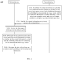
- FIG. 4 is a schematic flowchart of a wireless communication method 200 according to an embodiment of the present application. As shown in FIG. 4 , the method 200 may include some or all of the following contents.
- a network device determines first indication information carried in first control information according to whether the first control information carries scheduling information for scheduling data transmission on a target carrier, and the first indication information is used for indicating a state of at least one secondary carrier, and states of a carrier include a dormancy state and a non-dormancy state.
- the network device sends the first control information to a terminal device on a primary carrier.
- the terminal device receives the first control information sent by the network device on the primary carrier.
- the terminal device determines the first indication information carried in the first control information according to whether the first control information carries the scheduling information for scheduling the data transmission on the target carrier.
- the terminal device determines a state of the at least one secondary carrier according to the first indication information.
- the network device determines that the first indication information is carried in the first control information in a form of indication format A; if the first control information does not carry the scheduling information for scheduling the data transmission on the target carrier, the network device determines that the first indication information is carried in the first control information in the form of indication format B.
- the first indication information of the indication format A can indicate the state of the at least one secondary carrier according to a relatively large granularity; in contrast, the first indication information of the indication format B may use more bits in the first control information to elaborately indicate the state of each of the at least one secondary carrier.
- the first control information if the first control information carries the scheduling information for scheduling the data transmission on the target carrier, the first control information further includes but is not limited to at least one of the following:
- a data frequency domain resource indication for scheduling a physical downlink shared channel (PDSCH) or a physical uplink shared channel (PUSCH)
- a data time domain resource indication for scheduling the PDSCH or PUSCH
- MCS modulation and coding scheme
- power control for controlling the power control
- CSI channel state information
- the at least one secondary carrier is a secondary carrier that has a certain correspondence with the primary carrier, and this correspondence may be agreed upon by a protocol or configured by the network device.
- the target carrier is one of the following: the primary carrier, a secondary carrier in the dormancy state other than the at least one secondary carrier, and a secondary carrier in the non-dormancy state other than the at least one secondary carrier.
- the terminal device switches the state of the target carrier from the dormancy state to the non-dormancy state.
- the scheduling information can be used for scheduling uplink data transmission, and can also be used for scheduling downlink data transmission.
- the scheduling information is used for scheduling the uplink data transmission.
- the first control information is downlink control information (DCI) carried in the PDCCH.
- DCI downlink control information
- the terminal device is in the active period of the DRX cycle.
- the active period of the DRX cycle may also be referred to as the active time of the DRX cycle.
- the secondary carrier serving the terminal device automatically enters the dormancy state.
- step S210 may specifically be:
- step S240 may specifically be:
- the dedicated field or the multiple dedicated bits are pre-configured, or the dedicated field or the multiple dedicated bits are configured or indicated by the network device.
- the dedicated field or the multiple dedicated bits indicate states of secondary carriers in at least one secondary carrier group, and the at least one secondary carrier belongs to the at least one secondary carrier group.
- the at least one secondary carrier group is pre-configured, or the at least one secondary carrier group is configured or indicated by the network device.
- the dedicated field is a newly defined or newly configured field in the first control information, which does not conflict with an original field or bit in the first control information; similarly, the multiple dedicated bits are newly defined or newly configured bits in the first control information, which do not conflict with the original field or bit in the first control information.
- the multiple target bits multiplex bits occupied by at least one piece of information in the first control information.
- the at least one piece of information includes at least one of the following: frequency domain resource indication information, time domain resource indication information, power control domain, aperiodic measurement trigger information, MCS indication information, CSI trigger information, and BWP switching indication information.
- the multiple target bits are pre-configured, or the multiple target bits are configured or indicated by the network device.
- the multiple target bits respectively indicate a state of each of the at least one secondary carrier in a bitmap manner.
- the multiple target bits redefine a meaning of the bit occupied by the at least one piece of information in the first control information.
- 15 bits in the first control information are used as the multiple target bits, and the 15 bits respectively indicate states of 15 secondary carriers. For example, when a bit value is 1, it indicates that the state of the secondary carrier is the dormancy state, and when the bit value is 0, it indicates that the state of the secondary carrier is the non-dormancy state.
- the terminal device may determine whether the first control information carries the scheduling information
- the terminal device determines whether the first control information carries the scheduling information according to data channel indication information in the first control information.
- the data channel indication information can be a 1-bit data channel indicator.
- a value of the data channel indicator is 1, it is determined that the first control information carries the scheduling information, and when the value of the data channel indicator is 0, it is determined that the first control information does not carry the scheduling information.
- the terminal device determines whether the first control information carries the scheduling information according to a value of at least one of frequency domain scheduling information, time domain scheduling information, the power control domain, and the aperiodic measurement trigger information.
- the network device may also determine whether the first control information carries the scheduling information.
- the network device determines whether the first control information carries the scheduling information according to data channel indication information in the first control information.
- the network device determines whether the first control information carries the scheduling information according to the value of at least one of frequency domain scheduling information, time domain scheduling information, the power control domain, and the aperiodic measurement trigger information.
- the first indication information may indicate a state of each secondary carrier of the at least one secondary carrier, by activating a BWP that meets an indicated state in the each secondary carrier, and states of the BWP include a dormancy state and a non-dormancy state.
- the state of the secondary carrier may be indicated by the switching of one or more BWPs in this secondary carrier.
- the state of the BWP is consistent with the state of the secondary carrier to which the BWP belongs.
- the state of the BWP is the dormancy state
- the state of the secondary carrier to which the BWP belongs is also the dormancy state.
- the state of the secondary carrier to which the BWP belongs is also the non-dormancy state.
- the BWP in each secondary carrier is pre-configured, or the BWP in each secondary carrier is configured or indicated by the network device.
- the at least one secondary carrier includes a first secondary carrier
- the terminal device performs at least one of the following operations:
- the extended monitoring cycle of the PDCCH search space may be determined by a specific extension factor or a separate configuration.
- the reduced number of PDCCH blind detections or the number of channel estimation resources may be determined by a reduction factor or the separate configuration.
- the terminal device is in the active time of the DRX cycle.
- the secondary carrier automatically enters the dormancy state when the terminal device enters the active time.
- the terminal device receives DCI 1 through the primary carrier at time A, the DCI 1 contains the scheduling information for scheduling the data transmission on the primary carrier, and indication information 1 in the DCI 1 indicates that the state of the secondary carrier is the non-dormancy state.
- the state of the secondary carrier is changed from the dormancy state to the non-dormancy state.
- the terminal device receives DCI 2 through the primary carrier at time B.
- indication information 2 in the DCI 2 indicates that the state of the secondary carrier is the dormancy state.
- the state of the secondary carrier is changed from the non-dormancy state to the dormancy state.
- the PDCCH detection on this secondary carrier can be reduced.
- other power consumption operations such as signal measurement
- the number of receiving antennas (such as the maximum number of receiving antennas) of the terminal device can be reduced.
- the first indication information is used for indicating the state of the at least one secondary carrier, for example, a certain secondary carrier being in the dormancy state or the non-dormancy state.
- a certain secondary carrier being in the dormancy state or the non-dormancy state.
- it may be used for indicating the switching of some other energy-saving states of one or more secondary carriers.
- the energy-saving state of the carrier where the terminal device is located is switched through scheduling a control channel.
- the terminal device generally only needs to switch to the energy-saving state (dormancy state) when there is no data.
- scheduling can sometimes be turned off, and more bits in the control channel are used to elaborately control the state of each secondary carrier to achieve energy saving.
- the solution of the present application can also be used for scheduling, indicating the state of a group of secondary carriers according to a larger granularity, so as to achieve energy saving.
- the network device can more flexibly trigger the more refined energy-saving functions on the terminal side under the multi-secondary carrier configuration, and does not increase the control channel format.
- a dedicated energy-saving signal may not be added to indicate the energy-saving signal on each secondary carrier. Due to the large number of secondary carriers, the physical layer signaling overhead of the energy-saving signal dedicated to the secondary carrier will be very large. The solution of the present application does not require an additional bit field of the physical layer energy-saving signal, and can be compatible with the existing wake-up signal and DRX mechanism.
- the primary carrier can be used as an anchor point so that part or all of the secondary carriers enter the dormancy state or the non-dormancy state when the terminal device is in the DRX active period, and the response time is fast.
- the network device can still use other methods, such as BWP dynamic signaling conversion, timers, etc., to quickly trigger the terminal device to enter the non-dormancy state with the high data rate (non-energy-saving state).
- FIG. 6 shows a schematic block diagram illustrating a terminal device 300 according to an embodiment of the present application.
- the terminal device 300 includes:
- the processing unit 320 is further configured to determine the state of the at least one secondary carrier according to the first indication information.
- the target carrier is one of the following: the primary carrier, a secondary carrier in the dormancy state other than the at least one secondary carrier, and a secondary carrier in the non-dormancy state other than the at least one secondary carrier.
- the processing unit is further configured to switch a state of the target carrier from the dormancy state to the non-dormancy state.
- the processing unit 320 is specifically configured to:
- the dedicated field or the multiple dedicated bits are pre-configured, or the dedicated field or the multiple dedicated bits are configured or indicated by a network device.
- the dedicated field or the multiple dedicated bits indicate states of secondary carriers in at least one secondary carrier group, and the at least one secondary carrier belongs to the at least one secondary carrier group.
- the at least one secondary carrier group is pre-configured, or the at least one secondary carrier group is configured or indicated by the network device.
- the multiple target bits multiplex bits occupied by at least one piece of information among the first control information.
- the at least one piece of information includes at least one of the following: frequency domain resource indication information, time domain resource indication information, power control domain, aperiodic measurement trigger information, MCS indication information, CSI trigger information, and BWP switching indication information.
- the multiple target bits are pre-configured, or the multiple target bits are configured or indicated by the network device.
- the multiple target bits indicate a state of each of the at least one secondary carrier in a bitmap manner, respectively.
- the processing unit 320 is further configured to determine whether the first control information carries the scheduling information.
- the processing unit 320 is specifically configured to: determine whether the first control information carries the scheduling information according to data channel indication information in the first control information.
- the processing unit 320 is specifically configured to: determine whether the first control information carries the scheduling information according to a value of at least one of frequency domain scheduling information, time domain scheduling information, the power control domain, and the aperiodic measurement trigger information.
- the first indication information indicates a state of each secondary carrier of the at least one secondary carrier, by activating a BWP that meets an indicated state in the each secondary carrier, and states of the BWP include a dormancy state and a non-dormancy state.
- the state of the BWP is consistent with a state of a secondary carrier to which the BWP belongs.
- the BWP in each secondary carrier is pre-configured, or the BWP in each secondary carrier is configured or indicated by the network device.
- the at least one secondary carrier includes a first secondary carrier
- the processing unit 320 is further configured to:
- the processing unit 320 performs at least one of the following operations:
- the scheduling information is used for scheduling uplink data transmission.
- the first control information is DCI carried in the PDCCH.
- the terminal device is in the active period of the DRX cycle.
- terminal device 300 may correspond to the terminal device in the method embodiments of the present application, and the above and other operations and/or functions of each unit in the terminal device 300 are respectively for implementing the corresponding processes of the terminal device in the method 200 as shown in FIG. 4 .
- repeated descriptions are omitted here.
- FIG. 7 shows a schematic block diagram illustrating a network device 400 according to an embodiment of the present application.
- the network device 400 includes:
- the target carrier is one of the following: the primary carrier, a secondary carrier in the dormancy state other than the at least one secondary carrier, and a secondary carrier in the non-dormancy state other than the at least one secondary carrier.
- the scheduling information is further used for triggering a peer device to switch a state of the target carrier from the dormancy state to the non-dormancy state.
- the processing unit 410 is specifically configured to:
- the dedicated field or the multiple dedicated bits are configured or indicated by the network device.
- the dedicated field or the multiple dedicated bits indicate states of secondary carriers in at least one secondary carrier group, and the at least one secondary carrier belongs to the at least one secondary carrier group.
- the at least one secondary carrier group is configured or indicated by the network device.
- the multiple target bits multiplex bits occupied by at least one piece of information among the first control information.
- the at least one piece of information includes at least one of the following: frequency domain resource indication information, time domain resource indication information, power control domain, aperiodic measurement trigger information, MCS indication information, CSI trigger information, and BWP switching indication information.
- the multiple target bits are configured or indicated by the network device.
- the multiple target bits indicate a state of each of the at least one secondary carrier in a bitmap manner, respectively.
- the processing unit 410 is further configured to determine whether the first control information carries the scheduling information.
- the processing unit 410 is specifically configured to: determine whether the first control information carries the scheduling information according to data channel indication information in the first control information.
- the processing unit 410 is specifically configured to: determine whether the first control information carries the scheduling information according to a value of at least one of frequency domain scheduling information, time domain scheduling information, the power control domain, and the aperiodic measurement trigger information.
- the first indication information indicates a state of each secondary carrier of the at least one secondary carrier, by activating a BWP that meets an indicated state in the each secondary carrier, and states of the BWP include a dormancy state and a non-dormancy state.
- the state of the BWP is consistent with a state of a secondary carrier to which the BWP belongs.
- the BWP in each secondary carrier is pre-configured, or the BWP in each secondary carrier is configured or indicated by the network device.
- the scheduling information is used for scheduling uplink data transmission.
- the first control information is DCI carried in the PDCCH.
- the network device 400 may correspond to the network device in the method embodiments of the present application, and the above and other operations and/or functions of each unit in the network device 400 are respectively for implementing the corresponding processes of the network device in the method 200 shown in FIG. 4 .
- the network device 400 may correspond to the network device in the method embodiments of the present application, and the above and other operations and/or functions of each unit in the network device 400 are respectively for implementing the corresponding processes of the network device in the method 200 shown in FIG. 4 .
- details will not be repeated here.
- FIG. 8 is a schematic structural diagram illustrating a communication device 500 according to an embodiment of the present application.
- the communication device 500 shown in FIG. 8 includes a processor 510.
- the processor 510 may invoke a computer program from a memory and run the computer program, to implement the method in the embodiments of the present application.
- the communication device 500 may further include a memory 520.
- the processor 510 may invoke the computer program from the memory 520 and run the computer program, to implement the method in the embodiments of the present application.
- the memory 520 may be a component independent of the processor 510, or may be integrated into the processor 510.
- the communication device 500 may further include a transceiver 530.
- the processor 510 may control the transceiver 530 to communicate with another device, and specifically, the transceiver 530 may transmit information or data to another device, or receive information or data transmitted by another device.
- the transceiver 530 may include a transmitter and a receiver.
- the transceiver 530 may further include an antenna. There may be one or more antennas.
- the communication device 500 may be the network device or the base station in the embodiments of the present application, and the communication device 500 can implement corresponding procedures implemented by the network device or the base station in various methods in the embodiments of the present application. For brevity, details are not described herein again.
- the communication device 500 may be the mobile terminal/terminal in the embodiments of the present application, and the communication device 500 can implement corresponding procedures implemented by the mobile terminal/terminal device in various methods in the embodiments of the present application. For brevity, details are not described herein again.
- FIG. 9 is a schematic structural diagram illustrating a device according to an embodiment of the present application.
- the device 600 shown in FIG. 9 includes a processor 610.
- the processor 610 may invoke a computer program from a memory and run the computer program, to implement the method in the embodiments of the present application.
- the device 600 may further include a memory 620.
- the processor 610 may invoke the computer program from the memory 620 and run the computer program, to implement the method in the embodiments of the present application.
- the memory 620 may be a component independent of the processor 610, or may be integrated into the processor 610.
- the device 600 may further include an input interface 630.
- the processor 610 may control the input interface 630 to communicate with another device or chip, and specifically, the input interface 630 may obtain information or data transmitted by another device or chip.
- the device 600 may further include an output interface 640.
- the processor 610 may control the output interface 640 to communicate with another device or chip, and specifically, the output interface 640 may output information or data to another device or chip
- the device may be applied in the network device or the base station according to embodiments of the present application, and the device can implement corresponding procedures implemented by the network device or the base station in various methods in the embodiments of the present application. For brevity, details are not described herein again.
- the device may be applied to the mobile terminal/terminal device in the embodiments of the present application, and the device can implement corresponding procedures implemented by the mobile terminal/terminal device in various methods in the embodiments of the present application. For brevity, details are not described herein again.
- the device mentioned in the embodiments of the present application may also be a chip, for example, a system-level chip, a system chip, a chip system, a system on chip, or the like.
- FIG. 10 is a schematic structural diagram illustrating a communication system 700 according to an embodiment of the present application.
- the communication system 700 shown in FIG. 10 includes a terminal device 710 and a network device 720.
- the terminal device 710 can implement corresponding functions implemented by the terminal device in the foregoing method and the network device 720 can implement corresponding functions implemented by the network device or the base station in the foregoing method. For brevity, details are not described herein again.
- the processor of the embodiments of the present application may be an integrated circuit chip, has a signal processing capability, the steps of the foregoing method embodiment may be implemented by using a hardware integrated logic circuit in the processor and/or implemented by using an instruction in a software form.
- the foregoing processor may be a general purpose processor, a digital signal processor (DSP), a field programmable gate array (FPGA), an application specific integrated circuit (ASIC) or another programmable logic device, a transistor logic device, or a discrete hardware component.
- DSP digital signal processor
- FPGA field programmable gate array
- ASIC application specific integrated circuit
- the foregoing general purpose processor may be a microprocessor, or may be any conventional processor, or the like.
- Steps of the methods disclosed with reference to the embodiments of the present invention may be directly executed and completed by means of a hardware decoding processor, or may be executed and completed by using a combination of hardware and software modules in the decoding processor.
- the software module may be located in a mature storage medium in the field, such as a random access memory, a flash memory, a read-only memory, a programmable read-only memory, an electrically-erasable programmable memory, or a register.
- the storage medium is located in the memory, and the processor reads information in the memory and completes the steps in the foregoing method embodiments in combination with hardware of the processor.
- the memory in the embodiments of the present application may be a volatile memory or a non-volatile memory, or may include both a volatile memory and a non-volatile memory.
- the non-volatile memory may be a read-only memory (ROM), a programmable ROM (PROM), an erasable PROM (EPROM), an electrically EPROM (EEPROM), or a flash memory.
- the volatile memory may be a random access memory (RAM), and is used as an external cache.
- RAM random access memory
- DRAM dynamic random access memory
- SDRAM synchronous dynamic random access memory
- DDRSDRAM double data rate synchronous dynamic random access memory
- ESDRAM enhanced synchronous dynamic random access memory
- SLDRAM synchlink dynamic random access memory
- DRRAM direct rambus random access memory
- the memory is an example but is not intended for limitation.
- the memory in the embodiments of the present application may alternatively be a static RAM (SRAM), a dynamic RAM (DRAM), a synchronous DRAM (SDRAM), a double data rate SDRAM (DDR SDRAM), an enhanced SDRAM (ESDRAM), a synch link DRAM (SLDRAM), a direct rambus RAM (DR RAM), and the like. That is, the memory described in this embodiment of the present application is intended to include but is not limited to these memories and any other suitable type of memory.
- An embodiment of the present application further provides a computer readable storage medium.
- the computer readable storage medium is configured to store a computer program.
- the computer readable storage medium may be applied to the network device or the base station in the embodiments of the present application, and the computer program enables a computer to execute a corresponding procedure implemented by the network device or the base station in the methods of the embodiments of the present application.
- the computer program enables a computer to execute a corresponding procedure implemented by the network device or the base station in the methods of the embodiments of the present application.
- the computer readable storage medium may be applied to the mobile terminal/terminal device in the embodiments of the present application, and the computer program enables the computer to execute a corresponding procedure implemented by the mobile terminal/terminal device in the methods of the embodiments of the present application.
- the computer program enables the computer to execute a corresponding procedure implemented by the mobile terminal/terminal device in the methods of the embodiments of the present application.
- the present application further provides a computer program product.
- the computer program product includes a computer program instruction.
- the computer program product may be applied to the network device or the base station in the embodiments of the present application, and the computer program instruction enables the computer to execute a corresponding procedure implemented by the network device or the base station in the methods of the embodiments of the present application.
- the computer program instruction enables the computer to execute a corresponding procedure implemented by the network device or the base station in the methods of the embodiments of the present application.
- the computer program product may be applied to the mobile terminal/terminal device in the embodiments of the present application, and the computer program instruction enables the computer to execute a corresponding procedure implemented by the mobile terminal/terminal device in the methods of the embodiments of the present application.
- the computer program instruction enables the computer to execute a corresponding procedure implemented by the mobile terminal/terminal device in the methods of the embodiments of the present application.
- the present application further provides a computer program.
- the computer program may be applied to the network device or the base station in the embodiments of the present application, and when run on a computer, the computer program instruction enables the computer to execute a corresponding procedure implemented by the network device or the base station in the methods of the embodiments of the present application.
- the computer program instruction enables the computer to execute a corresponding procedure implemented by the network device or the base station in the methods of the embodiments of the present application.
- the computer program may be applied to the mobile terminal/terminal device in the embodiments of the present application, and when run on a computer, the computer program instruction enables the computer to execute a corresponding procedure implemented by the mobile terminal/terminal device in the methods of the embodiments of the present application.
- the computer program instruction enables the computer to execute a corresponding procedure implemented by the mobile terminal/terminal device in the methods of the embodiments of the present application.
- the disclosed system, apparatus, and method may be implemented in other manners.
- the apparatus embodiments described above are merely examples.
- the unit division is merely logical function division, and there may be other division manners in actual implementation.
- a plurality of units or components may be combined or integrated into another system, or some features may be ignored or not performed.
- the displayed or discussed mutual couplings or direct couplings or communication connections may be implemented by using some interfaces.
- the indirect couplings or communication connections between the apparatuses or units may be implemented in electrical, mechanical, or other forms.
- the units described as separate parts may or may not be physically separate, and the parts displayed as units may or may not be physical units, may be located in one position, or may be distributed on multiple network units. Some of or all of the units may be selected according to actual needs to achieve the objectives of the solutions of the embodiments.
- the functions When the functions are implemented in the form of a software functional unit and sold or used as an independent product, the functions may be stored in a computer-readable storage medium.
- the software product is stored in a storage medium, and includes several instructions for instructing a computer device (which may be a personal computer, a server, or a network device) to perform all or some of the steps of the methods described in the embodiments of the present application.
- the foregoing storage medium includes: any medium that can store program code, such as a USB flash drive, a removable hard disk, a read-only memory (ROM), a random access memory (RAM), a magnetic disk, or an optical disc.
Landscapes
- Engineering & Computer Science (AREA)
- Signal Processing (AREA)
- Computer Networks & Wireless Communication (AREA)
- Mobile Radio Communication Systems (AREA)
Applications Claiming Priority (1)
| Application Number | Priority Date | Filing Date | Title |
|---|---|---|---|
| PCT/CN2019/114802 WO2021081918A1 (fr) | 2019-10-31 | 2019-10-31 | Procédé de communication sans fil, dispositif terminal et dispositif de réseau |
Publications (3)
| Publication Number | Publication Date |
|---|---|
| EP4007400A1 true EP4007400A1 (fr) | 2022-06-01 |
| EP4007400A4 EP4007400A4 (fr) | 2022-07-27 |
| EP4007400B1 EP4007400B1 (fr) | 2024-07-03 |
Family
ID=75715692
Family Applications (1)
| Application Number | Title | Priority Date | Filing Date |
|---|---|---|---|
| EP19950276.6A Active EP4007400B1 (fr) | 2019-10-31 | 2019-10-31 | Procédé de communication sans fil, dispositif terminal et dispositif de réseau |
Country Status (7)
| Country | Link |
|---|---|
| US (2) | US12328671B2 (fr) |
| EP (1) | EP4007400B1 (fr) |
| JP (1) | JP7457797B2 (fr) |
| KR (1) | KR20220092491A (fr) |
| CN (2) | CN114337969B (fr) |
| MX (1) | MX2022004573A (fr) |
| WO (1) | WO2021081918A1 (fr) |
Families Citing this family (8)
| Publication number | Priority date | Publication date | Assignee | Title |
|---|---|---|---|---|
| EP4231742A4 (fr) * | 2020-10-15 | 2023-11-01 | Beijing Xiaomi Mobile Software Co., Ltd. | Procédé et dispositif de programmation entre porteuses, et support de stockage |
| WO2023130470A1 (fr) * | 2022-01-10 | 2023-07-13 | 北京小米移动软件有限公司 | Procédé et appareil de suspension d'écoute, et dispositif de communication et support de stockage |
| KR20250048250A (ko) * | 2022-08-12 | 2025-04-08 | 삼성전자주식회사 | 적응 정보를 사용하여 공간 영역에서 네트워크 에너지를 절감하기 위한 방법들 및 시스템들 |
| CN119586315A (zh) * | 2022-11-01 | 2025-03-07 | Oppo广东移动通信有限公司 | 一种drx实现方法及装置、终端设备 |
| CN118265118A (zh) * | 2022-12-28 | 2024-06-28 | 华为技术有限公司 | 一种节能方法及装置 |
| EP4665078A4 (fr) * | 2023-02-07 | 2026-04-01 | Beijing Xiaomi Mobile Software Co Ltd | Procédé et appareil de surveillance, de traitement ou d'envoi d'informations de liaison montante, et support d'enregistrement lisible |
| WO2024239173A1 (fr) * | 2023-05-19 | 2024-11-28 | 北京小米移动软件有限公司 | Procédé et appareil de transmission d'informations de commande de liaison descendante, et support de stockage |
| CN121510226A (zh) * | 2024-08-09 | 2026-02-10 | 华为技术有限公司 | 信号传输方法、通信装置及通信系统 |
Family Cites Families (11)
| Publication number | Priority date | Publication date | Assignee | Title |
|---|---|---|---|---|
| KR101723411B1 (ko) * | 2009-08-21 | 2017-04-05 | 엘지전자 주식회사 | 멀티 캐리어 시스템의 슬립모드 동작 방법 및 장치 |
| EP2360864A1 (fr) | 2010-02-12 | 2011-08-24 | Panasonic Corporation | (Dés)activation de véhicules de composants dans les systèmes de communication utilisant une agrégation de porteuses |
| US9674727B2 (en) * | 2014-01-17 | 2017-06-06 | Qualcomm Incorporated | Indication of cell mode and CSI feedback rules for cell on-off procedure |
| US10721720B2 (en) * | 2014-01-30 | 2020-07-21 | Qualcomm Incorporated | Cell On-Off procedure for dual connectivity |
| EP3073693B1 (fr) * | 2015-03-24 | 2020-07-22 | Panasonic Intellectual Property Corporation of America | Adaptation de précodage pdsch dans des bandes non autorisées pour lte |
| CN113473619B (zh) | 2017-09-14 | 2022-04-12 | 华为技术有限公司 | 信号处理的方法和装置 |
| CN109788558A (zh) * | 2017-11-14 | 2019-05-21 | 北京展讯高科通信技术有限公司 | 部分载波带宽激活/去激活方法、装置及基站 |
| US11297674B2 (en) * | 2018-02-14 | 2022-04-05 | Samsung Electronics Co., Ltd. | Method and apparatus for power savings at a user equipment |
| US10924250B2 (en) * | 2018-09-13 | 2021-02-16 | Samsung Electronics Co., Ltd. | UE operation with reduced power consumption |
| US12389400B2 (en) * | 2019-01-29 | 2025-08-12 | Samsung Electronics Co., Ltd. | Method and device for by-link activation and deactivation for reducing power consumption in next generation mobile communication system |
| US11917709B2 (en) * | 2019-10-16 | 2024-02-27 | Intel Corporation | L1 signalling for transitioning secondary cells (SCells) between dormancy and non-dormancy in 5G NR |
-
2019
- 2019-10-31 EP EP19950276.6A patent/EP4007400B1/fr active Active
- 2019-10-31 CN CN202111667813.2A patent/CN114337969B/zh active Active
- 2019-10-31 MX MX2022004573A patent/MX2022004573A/es unknown
- 2019-10-31 WO PCT/CN2019/114802 patent/WO2021081918A1/fr not_active Ceased
- 2019-10-31 JP JP2022516446A patent/JP7457797B2/ja active Active
- 2019-10-31 KR KR1020227008871A patent/KR20220092491A/ko active Pending
- 2019-10-31 CN CN201980093967.XA patent/CN113557777A/zh active Pending
-
2022
- 2022-02-23 US US17/678,607 patent/US12328671B2/en active Active
-
2025
- 2025-05-21 US US19/214,647 patent/US20250287307A1/en active Pending
Also Published As
| Publication number | Publication date |
|---|---|
| US20220191790A1 (en) | 2022-06-16 |
| CN114337969A (zh) | 2022-04-12 |
| EP4007400B1 (fr) | 2024-07-03 |
| US12328671B2 (en) | 2025-06-10 |
| JP2023504336A (ja) | 2023-02-03 |
| JP7457797B2 (ja) | 2024-03-28 |
| CN114337969B (zh) | 2023-12-26 |
| MX2022004573A (es) | 2022-05-06 |
| WO2021081918A1 (fr) | 2021-05-06 |
| EP4007400A4 (fr) | 2022-07-27 |
| KR20220092491A (ko) | 2022-07-01 |
| CN113557777A (zh) | 2021-10-26 |
| US20250287307A1 (en) | 2025-09-11 |
Similar Documents
| Publication | Publication Date | Title |
|---|---|---|
| US12328671B2 (en) | Wireless communication method, terminal device, and network device | |
| US12185243B2 (en) | Method, communications device, and network device for monitoring physical downlink control channel, communications device, and network device using wake-up signal (WUS) | |
| US11937254B2 (en) | Wireless communcation method, terminal device, and network device | |
| CN112740763B (zh) | 无线通信方法、终端设备和网络设备 | |
| US11962387B2 (en) | Wireless communication method and apparatus | |
| US20230328690A1 (en) | Wireless communication method, terminal device and network device | |
| US20220225274A1 (en) | Paging message detection method, apparatus, and communication device | |
| US20220007408A1 (en) | Pdcch monitoring method, terminal device, and network device | |
| US20220338123A1 (en) | Switching method, terminal device, network device, and communication system | |
| CN110809331A (zh) | 接收参考信号的方法和通信设备 | |
| US12526768B2 (en) | Energy saving method, terminal device, and network device | |
| EP3890405A1 (fr) | Procédé et appareil de communication sans fil | |
| US20220124722A1 (en) | Bwp switching method and terminal device | |
| US20230308924A1 (en) | Measurement method, terminal device, and network device | |
| WO2021087987A1 (fr) | Procédé de communication sans fil, équipement terminal et dispositif de réseau | |
| WO2023141760A1 (fr) | Procédé de communication sans fil, dispositif terminal et dispositif de réseau |
Legal Events
| Date | Code | Title | Description |
|---|---|---|---|
| STAA | Information on the status of an ep patent application or granted ep patent |
Free format text: STATUS: THE INTERNATIONAL PUBLICATION HAS BEEN MADE |
|
| PUAI | Public reference made under article 153(3) epc to a published international application that has entered the european phase |
Free format text: ORIGINAL CODE: 0009012 |
|
| STAA | Information on the status of an ep patent application or granted ep patent |
Free format text: STATUS: REQUEST FOR EXAMINATION WAS MADE |
|
| 17P | Request for examination filed |
Effective date: 20220222 |
|
| AK | Designated contracting states |
Kind code of ref document: A1 Designated state(s): AL AT BE BG CH CY CZ DE DK EE ES FI FR GB GR HR HU IE IS IT LI LT LU LV MC MK MT NL NO PL PT RO RS SE SI SK SM TR |
|
| A4 | Supplementary search report drawn up and despatched |
Effective date: 20220624 |
|
| RIC1 | Information provided on ipc code assigned before grant |
Ipc: H04L 5/00 20060101ALI20220620BHEP Ipc: H04W 72/04 20090101AFI20220620BHEP |
|
| DAV | Request for validation of the european patent (deleted) | ||
| DAX | Request for extension of the european patent (deleted) | ||
| STAA | Information on the status of an ep patent application or granted ep patent |
Free format text: STATUS: EXAMINATION IS IN PROGRESS |
|
| 17Q | First examination report despatched |
Effective date: 20230224 |
|
| REG | Reference to a national code |
Ref country code: DE Ref legal event code: R079 Ipc: H04W0052020000 Ref country code: DE Ref legal event code: R079 Ref document number: 602019054836 Country of ref document: DE Free format text: PREVIOUS MAIN CLASS: H04W0072040000 Ipc: H04W0052020000 |
|
| GRAP | Despatch of communication of intention to grant a patent |
Free format text: ORIGINAL CODE: EPIDOSNIGR1 |
|
| STAA | Information on the status of an ep patent application or granted ep patent |
Free format text: STATUS: GRANT OF PATENT IS INTENDED |
|
| RIC1 | Information provided on ipc code assigned before grant |
Ipc: H04W 76/15 20180101ALN20240206BHEP Ipc: H04W 72/23 20230101ALN20240206BHEP Ipc: H04W 76/27 20180101ALI20240206BHEP Ipc: H04L 5/00 20060101ALI20240206BHEP Ipc: H04W 72/04 20090101ALI20240206BHEP Ipc: H04W 52/02 20090101AFI20240206BHEP |
|
| INTG | Intention to grant announced |
Effective date: 20240222 |
|
| GRAS | Grant fee paid |
Free format text: ORIGINAL CODE: EPIDOSNIGR3 |
|
| GRAA | (expected) grant |
Free format text: ORIGINAL CODE: 0009210 |
|
| STAA | Information on the status of an ep patent application or granted ep patent |
Free format text: STATUS: THE PATENT HAS BEEN GRANTED |
|
| AK | Designated contracting states |
Kind code of ref document: B1 Designated state(s): AL AT BE BG CH CY CZ DE DK EE ES FI FR GB GR HR HU IE IS IT LI LT LU LV MC MK MT NL NO PL PT RO RS SE SI SK SM TR |
|
| REG | Reference to a national code |
Ref country code: CH Ref legal event code: EP |
|
| REG | Reference to a national code |
Ref country code: DE Ref legal event code: R096 Ref document number: 602019054836 Country of ref document: DE |
|
| REG | Reference to a national code |
Ref country code: NL Ref legal event code: FP |
|
| P01 | Opt-out of the competence of the unified patent court (upc) registered |
Free format text: CASE NUMBER: APP_49591/2024 Effective date: 20240902 |
|
| REG | Reference to a national code |
Ref country code: LT Ref legal event code: MG9D |
|
| PG25 | Lapsed in a contracting state [announced via postgrant information from national office to epo] |
Ref country code: PT Free format text: LAPSE BECAUSE OF FAILURE TO SUBMIT A TRANSLATION OF THE DESCRIPTION OR TO PAY THE FEE WITHIN THE PRESCRIBED TIME-LIMIT Effective date: 20241104 |
|
| REG | Reference to a national code |
Ref country code: AT Ref legal event code: MK05 Ref document number: 1701064 Country of ref document: AT Kind code of ref document: T Effective date: 20240703 |
|
| PG25 | Lapsed in a contracting state [announced via postgrant information from national office to epo] |
Ref country code: PT Free format text: LAPSE BECAUSE OF FAILURE TO SUBMIT A TRANSLATION OF THE DESCRIPTION OR TO PAY THE FEE WITHIN THE PRESCRIBED TIME-LIMIT Effective date: 20241104 |
|
| PG25 | Lapsed in a contracting state [announced via postgrant information from national office to epo] |
Ref country code: NO Free format text: LAPSE BECAUSE OF FAILURE TO SUBMIT A TRANSLATION OF THE DESCRIPTION OR TO PAY THE FEE WITHIN THE PRESCRIBED TIME-LIMIT Effective date: 20241003 |
|
| PG25 | Lapsed in a contracting state [announced via postgrant information from national office to epo] |
Ref country code: GR Free format text: LAPSE BECAUSE OF FAILURE TO SUBMIT A TRANSLATION OF THE DESCRIPTION OR TO PAY THE FEE WITHIN THE PRESCRIBED TIME-LIMIT Effective date: 20241004 Ref country code: FI Free format text: LAPSE BECAUSE OF FAILURE TO SUBMIT A TRANSLATION OF THE DESCRIPTION OR TO PAY THE FEE WITHIN THE PRESCRIBED TIME-LIMIT Effective date: 20240703 Ref country code: PL Free format text: LAPSE BECAUSE OF FAILURE TO SUBMIT A TRANSLATION OF THE DESCRIPTION OR TO PAY THE FEE WITHIN THE PRESCRIBED TIME-LIMIT Effective date: 20240703 |
|
| PG25 | Lapsed in a contracting state [announced via postgrant information from national office to epo] |
Ref country code: BG Free format text: LAPSE BECAUSE OF FAILURE TO SUBMIT A TRANSLATION OF THE DESCRIPTION OR TO PAY THE FEE WITHIN THE PRESCRIBED TIME-LIMIT Effective date: 20240703 |
|
| PG25 | Lapsed in a contracting state [announced via postgrant information from national office to epo] |
Ref country code: LV Free format text: LAPSE BECAUSE OF FAILURE TO SUBMIT A TRANSLATION OF THE DESCRIPTION OR TO PAY THE FEE WITHIN THE PRESCRIBED TIME-LIMIT Effective date: 20240703 |
|
| PG25 | Lapsed in a contracting state [announced via postgrant information from national office to epo] |
Ref country code: IS Free format text: LAPSE BECAUSE OF FAILURE TO SUBMIT A TRANSLATION OF THE DESCRIPTION OR TO PAY THE FEE WITHIN THE PRESCRIBED TIME-LIMIT Effective date: 20241103 Ref country code: AT Free format text: LAPSE BECAUSE OF FAILURE TO SUBMIT A TRANSLATION OF THE DESCRIPTION OR TO PAY THE FEE WITHIN THE PRESCRIBED TIME-LIMIT Effective date: 20240703 |
|
| PG25 | Lapsed in a contracting state [announced via postgrant information from national office to epo] |
Ref country code: CZ Free format text: LAPSE BECAUSE OF FAILURE TO SUBMIT A TRANSLATION OF THE DESCRIPTION OR TO PAY THE FEE WITHIN THE PRESCRIBED TIME-LIMIT Effective date: 20240703 Ref country code: HR Free format text: LAPSE BECAUSE OF FAILURE TO SUBMIT A TRANSLATION OF THE DESCRIPTION OR TO PAY THE FEE WITHIN THE PRESCRIBED TIME-LIMIT Effective date: 20240703 |
|
| PG25 | Lapsed in a contracting state [announced via postgrant information from national office to epo] |
Ref country code: ES Free format text: LAPSE BECAUSE OF FAILURE TO SUBMIT A TRANSLATION OF THE DESCRIPTION OR TO PAY THE FEE WITHIN THE PRESCRIBED TIME-LIMIT Effective date: 20240703 Ref country code: RS Free format text: LAPSE BECAUSE OF FAILURE TO SUBMIT A TRANSLATION OF THE DESCRIPTION OR TO PAY THE FEE WITHIN THE PRESCRIBED TIME-LIMIT Effective date: 20241003 |
|
| PG25 | Lapsed in a contracting state [announced via postgrant information from national office to epo] |
Ref country code: RS Free format text: LAPSE BECAUSE OF FAILURE TO SUBMIT A TRANSLATION OF THE DESCRIPTION OR TO PAY THE FEE WITHIN THE PRESCRIBED TIME-LIMIT Effective date: 20241003 Ref country code: PL Free format text: LAPSE BECAUSE OF FAILURE TO SUBMIT A TRANSLATION OF THE DESCRIPTION OR TO PAY THE FEE WITHIN THE PRESCRIBED TIME-LIMIT Effective date: 20240703 Ref country code: NO Free format text: LAPSE BECAUSE OF FAILURE TO SUBMIT A TRANSLATION OF THE DESCRIPTION OR TO PAY THE FEE WITHIN THE PRESCRIBED TIME-LIMIT Effective date: 20241003 Ref country code: LV Free format text: LAPSE BECAUSE OF FAILURE TO SUBMIT A TRANSLATION OF THE DESCRIPTION OR TO PAY THE FEE WITHIN THE PRESCRIBED TIME-LIMIT Effective date: 20240703 Ref country code: IS Free format text: LAPSE BECAUSE OF FAILURE TO SUBMIT A TRANSLATION OF THE DESCRIPTION OR TO PAY THE FEE WITHIN THE PRESCRIBED TIME-LIMIT Effective date: 20241103 Ref country code: HR Free format text: LAPSE BECAUSE OF FAILURE TO SUBMIT A TRANSLATION OF THE DESCRIPTION OR TO PAY THE FEE WITHIN THE PRESCRIBED TIME-LIMIT Effective date: 20240703 Ref country code: GR Free format text: LAPSE BECAUSE OF FAILURE TO SUBMIT A TRANSLATION OF THE DESCRIPTION OR TO PAY THE FEE WITHIN THE PRESCRIBED TIME-LIMIT Effective date: 20241004 Ref country code: FI Free format text: LAPSE BECAUSE OF FAILURE TO SUBMIT A TRANSLATION OF THE DESCRIPTION OR TO PAY THE FEE WITHIN THE PRESCRIBED TIME-LIMIT Effective date: 20240703 Ref country code: ES Free format text: LAPSE BECAUSE OF FAILURE TO SUBMIT A TRANSLATION OF THE DESCRIPTION OR TO PAY THE FEE WITHIN THE PRESCRIBED TIME-LIMIT Effective date: 20240703 Ref country code: CZ Free format text: LAPSE BECAUSE OF FAILURE TO SUBMIT A TRANSLATION OF THE DESCRIPTION OR TO PAY THE FEE WITHIN THE PRESCRIBED TIME-LIMIT Effective date: 20240703 Ref country code: BG Free format text: LAPSE BECAUSE OF FAILURE TO SUBMIT A TRANSLATION OF THE DESCRIPTION OR TO PAY THE FEE WITHIN THE PRESCRIBED TIME-LIMIT Effective date: 20240703 Ref country code: AT Free format text: LAPSE BECAUSE OF FAILURE TO SUBMIT A TRANSLATION OF THE DESCRIPTION OR TO PAY THE FEE WITHIN THE PRESCRIBED TIME-LIMIT Effective date: 20240703 |
|
| REG | Reference to a national code |
Ref country code: DE Ref legal event code: R097 Ref document number: 602019054836 Country of ref document: DE |
|
| PG25 | Lapsed in a contracting state [announced via postgrant information from national office to epo] |
Ref country code: RO Free format text: LAPSE BECAUSE OF FAILURE TO SUBMIT A TRANSLATION OF THE DESCRIPTION OR TO PAY THE FEE WITHIN THE PRESCRIBED TIME-LIMIT Effective date: 20240703 Ref country code: DK Free format text: LAPSE BECAUSE OF FAILURE TO SUBMIT A TRANSLATION OF THE DESCRIPTION OR TO PAY THE FEE WITHIN THE PRESCRIBED TIME-LIMIT Effective date: 20240703 Ref country code: SM Free format text: LAPSE BECAUSE OF FAILURE TO SUBMIT A TRANSLATION OF THE DESCRIPTION OR TO PAY THE FEE WITHIN THE PRESCRIBED TIME-LIMIT Effective date: 20240703 |
|
| PG25 | Lapsed in a contracting state [announced via postgrant information from national office to epo] |
Ref country code: EE Free format text: LAPSE BECAUSE OF FAILURE TO SUBMIT A TRANSLATION OF THE DESCRIPTION OR TO PAY THE FEE WITHIN THE PRESCRIBED TIME-LIMIT Effective date: 20240703 |
|
| PG25 | Lapsed in a contracting state [announced via postgrant information from national office to epo] |
Ref country code: SK Free format text: LAPSE BECAUSE OF FAILURE TO SUBMIT A TRANSLATION OF THE DESCRIPTION OR TO PAY THE FEE WITHIN THE PRESCRIBED TIME-LIMIT Effective date: 20240703 Ref country code: IT Free format text: LAPSE BECAUSE OF FAILURE TO SUBMIT A TRANSLATION OF THE DESCRIPTION OR TO PAY THE FEE WITHIN THE PRESCRIBED TIME-LIMIT Effective date: 20240703 |
|
| PLBE | No opposition filed within time limit |
Free format text: ORIGINAL CODE: 0009261 |
|
| STAA | Information on the status of an ep patent application or granted ep patent |
Free format text: STATUS: NO OPPOSITION FILED WITHIN TIME LIMIT |
|
| REG | Reference to a national code |
Ref country code: CH Ref legal event code: PL |
|
| 26N | No opposition filed |
Effective date: 20250404 |
|
| PG25 | Lapsed in a contracting state [announced via postgrant information from national office to epo] |
Ref country code: MC Free format text: LAPSE BECAUSE OF FAILURE TO SUBMIT A TRANSLATION OF THE DESCRIPTION OR TO PAY THE FEE WITHIN THE PRESCRIBED TIME-LIMIT Effective date: 20240703 |
|
| PG25 | Lapsed in a contracting state [announced via postgrant information from national office to epo] |
Ref country code: LU Free format text: LAPSE BECAUSE OF NON-PAYMENT OF DUE FEES Effective date: 20241031 Ref country code: BE Free format text: LAPSE BECAUSE OF NON-PAYMENT OF DUE FEES Effective date: 20241031 |
|
| PG25 | Lapsed in a contracting state [announced via postgrant information from national office to epo] |
Ref country code: CH Free format text: LAPSE BECAUSE OF NON-PAYMENT OF DUE FEES Effective date: 20241031 |
|
| REG | Reference to a national code |
Ref country code: BE Ref legal event code: MM Effective date: 20241031 |
|
| PG25 | Lapsed in a contracting state [announced via postgrant information from national office to epo] |
Ref country code: SE Free format text: LAPSE BECAUSE OF FAILURE TO SUBMIT A TRANSLATION OF THE DESCRIPTION OR TO PAY THE FEE WITHIN THE PRESCRIBED TIME-LIMIT Effective date: 20240703 |
|
| PG25 | Lapsed in a contracting state [announced via postgrant information from national office to epo] |
Ref country code: IE Free format text: LAPSE BECAUSE OF NON-PAYMENT OF DUE FEES Effective date: 20241031 |
|
| PGFP | Annual fee paid to national office [announced via postgrant information from national office to epo] |
Ref country code: NL Payment date: 20251027 Year of fee payment: 7 |
|
| PGFP | Annual fee paid to national office [announced via postgrant information from national office to epo] |
Ref country code: DE Payment date: 20251027 Year of fee payment: 7 |
|
| PGFP | Annual fee paid to national office [announced via postgrant information from national office to epo] |
Ref country code: GB Payment date: 20251024 Year of fee payment: 7 |
|
| PGFP | Annual fee paid to national office [announced via postgrant information from national office to epo] |
Ref country code: FR Payment date: 20251028 Year of fee payment: 7 |
|
| PG25 | Lapsed in a contracting state [announced via postgrant information from national office to epo] |
Ref country code: HU Free format text: LAPSE BECAUSE OF FAILURE TO SUBMIT A TRANSLATION OF THE DESCRIPTION OR TO PAY THE FEE WITHIN THE PRESCRIBED TIME-LIMIT; INVALID AB INITIO Effective date: 20191031 |
|
| PG25 | Lapsed in a contracting state [announced via postgrant information from national office to epo] |
Ref country code: CY Free format text: LAPSE BECAUSE OF FAILURE TO SUBMIT A TRANSLATION OF THE DESCRIPTION OR TO PAY THE FEE WITHIN THE PRESCRIBED TIME-LIMIT; INVALID AB INITIO Effective date: 20191031 |