EP4007447A1 - Élément chauffant plan de type film permettant d'empêcher des ondes électromagnétiques - Google Patents
Élément chauffant plan de type film permettant d'empêcher des ondes électromagnétiques Download PDFInfo
- Publication number
- EP4007447A1 EP4007447A1 EP20843244.3A EP20843244A EP4007447A1 EP 4007447 A1 EP4007447 A1 EP 4007447A1 EP 20843244 A EP20843244 A EP 20843244A EP 4007447 A1 EP4007447 A1 EP 4007447A1
- Authority
- EP
- European Patent Office
- Prior art keywords
- center
- copper foil
- heating unit
- carbon
- adjacent copper
- Prior art date
- Legal status (The legal status is an assumption and is not a legal conclusion. Google has not performed a legal analysis and makes no representation as to the accuracy of the status listed.)
- Granted
Links
Images


Classifications
-
- F—MECHANICAL ENGINEERING; LIGHTING; HEATING; WEAPONS; BLASTING
- F24—HEATING; RANGES; VENTILATING
- F24D—DOMESTIC- OR SPACE-HEATING SYSTEMS, e.g. CENTRAL HEATING SYSTEMS; DOMESTIC HOT-WATER SUPPLY SYSTEMS; ELEMENTS OR COMPONENTS THEREFOR
- F24D13/00—Electric heating systems
- F24D13/02—Electric heating systems solely using resistance heating, e.g. underfloor heating
- F24D13/022—Electric heating systems solely using resistance heating, e.g. underfloor heating resistances incorporated in construction elements
- F24D13/024—Electric heating systems solely using resistance heating, e.g. underfloor heating resistances incorporated in construction elements in walls, floors, ceilings
-
- H—ELECTRICITY
- H05—ELECTRIC TECHNIQUES NOT OTHERWISE PROVIDED FOR
- H05B—ELECTRIC HEATING; ELECTRIC LIGHT SOURCES NOT OTHERWISE PROVIDED FOR; CIRCUIT ARRANGEMENTS FOR ELECTRIC LIGHT SOURCES, IN GENERAL
- H05B3/00—Ohmic-resistance heating
- H05B3/20—Heating elements having extended surface area substantially in a two-dimensional [2D] plane, e.g. plate-heater
- H05B3/22—Heating elements having extended surface area substantially in a two-dimensional [2D] plane, e.g. plate-heater non-flexible
-
- H—ELECTRICITY
- H05—ELECTRIC TECHNIQUES NOT OTHERWISE PROVIDED FOR
- H05B—ELECTRIC HEATING; ELECTRIC LIGHT SOURCES NOT OTHERWISE PROVIDED FOR; CIRCUIT ARRANGEMENTS FOR ELECTRIC LIGHT SOURCES, IN GENERAL
- H05B3/00—Ohmic-resistance heating
- H05B3/20—Heating elements having extended surface area substantially in a two-dimensional [2D] plane, e.g. plate-heater
-
- H—ELECTRICITY
- H05—ELECTRIC TECHNIQUES NOT OTHERWISE PROVIDED FOR
- H05B—ELECTRIC HEATING; ELECTRIC LIGHT SOURCES NOT OTHERWISE PROVIDED FOR; CIRCUIT ARRANGEMENTS FOR ELECTRIC LIGHT SOURCES, IN GENERAL
- H05B3/00—Ohmic-resistance heating
- H05B3/02—Details
-
- H—ELECTRICITY
- H05—ELECTRIC TECHNIQUES NOT OTHERWISE PROVIDED FOR
- H05B—ELECTRIC HEATING; ELECTRIC LIGHT SOURCES NOT OTHERWISE PROVIDED FOR; CIRCUIT ARRANGEMENTS FOR ELECTRIC LIGHT SOURCES, IN GENERAL
- H05B3/00—Ohmic-resistance heating
- H05B3/02—Details
- H05B3/03—Electrodes
-
- H—ELECTRICITY
- H05—ELECTRIC TECHNIQUES NOT OTHERWISE PROVIDED FOR
- H05B—ELECTRIC HEATING; ELECTRIC LIGHT SOURCES NOT OTHERWISE PROVIDED FOR; CIRCUIT ARRANGEMENTS FOR ELECTRIC LIGHT SOURCES, IN GENERAL
- H05B3/00—Ohmic-resistance heating
- H05B3/10—Heating elements characterised by the composition or nature of the materials or by the arrangement of the conductor
- H05B3/12—Heating elements characterised by the composition or nature of the materials or by the arrangement of the conductor characterised by the composition or nature of the conductive material
- H05B3/14—Heating elements characterised by the composition or nature of the materials or by the arrangement of the conductor characterised by the composition or nature of the conductive material the material being non-metallic
- H05B3/145—Carbon only, e.g. carbon black, graphite
-
- H—ELECTRICITY
- H05—ELECTRIC TECHNIQUES NOT OTHERWISE PROVIDED FOR
- H05B—ELECTRIC HEATING; ELECTRIC LIGHT SOURCES NOT OTHERWISE PROVIDED FOR; CIRCUIT ARRANGEMENTS FOR ELECTRIC LIGHT SOURCES, IN GENERAL
- H05B3/00—Ohmic-resistance heating
- H05B3/20—Heating elements having extended surface area substantially in a two-dimensional [2D] plane, e.g. plate-heater
- H05B3/22—Heating elements having extended surface area substantially in a two-dimensional [2D] plane, e.g. plate-heater non-flexible
- H05B3/26—Heating elements having extended surface area substantially in a two-dimensional [2D] plane, e.g. plate-heater non-flexible heating conductor mounted on insulating base
- H05B3/267—Heating elements having extended surface area substantially in a two-dimensional [2D] plane, e.g. plate-heater non-flexible heating conductor mounted on insulating base the insulating base being an organic material, e.g. plastic
-
- H—ELECTRICITY
- H05—ELECTRIC TECHNIQUES NOT OTHERWISE PROVIDED FOR
- H05B—ELECTRIC HEATING; ELECTRIC LIGHT SOURCES NOT OTHERWISE PROVIDED FOR; CIRCUIT ARRANGEMENTS FOR ELECTRIC LIGHT SOURCES, IN GENERAL
- H05B3/00—Ohmic-resistance heating
- H05B3/20—Heating elements having extended surface area substantially in a two-dimensional [2D] plane, e.g. plate-heater
- H05B3/34—Heating elements having extended surface area substantially in a two-dimensional [2D] plane, e.g. plate-heater flexible, e.g. heating nets or webs
-
- H—ELECTRICITY
- H05—ELECTRIC TECHNIQUES NOT OTHERWISE PROVIDED FOR
- H05K—PRINTED CIRCUITS; CASINGS OR CONSTRUCTIONAL DETAILS OF ELECTRIC APPARATUS; MANUFACTURE OF ASSEMBLAGES OF ELECTRICAL COMPONENTS
- H05K9/00—Screening of apparatus or components against electric or magnetic fields
-
- H—ELECTRICITY
- H05—ELECTRIC TECHNIQUES NOT OTHERWISE PROVIDED FOR
- H05K—PRINTED CIRCUITS; CASINGS OR CONSTRUCTIONAL DETAILS OF ELECTRIC APPARATUS; MANUFACTURE OF ASSEMBLAGES OF ELECTRICAL COMPONENTS
- H05K9/00—Screening of apparatus or components against electric or magnetic fields
- H05K9/0071—Active shielding
-
- H—ELECTRICITY
- H05—ELECTRIC TECHNIQUES NOT OTHERWISE PROVIDED FOR
- H05B—ELECTRIC HEATING; ELECTRIC LIGHT SOURCES NOT OTHERWISE PROVIDED FOR; CIRCUIT ARRANGEMENTS FOR ELECTRIC LIGHT SOURCES, IN GENERAL
- H05B2203/00—Aspects relating to Ohmic resistive heating covered by group H05B3/00
- H05B2203/011—Heaters using laterally extending conductive material as connecting means
-
- H—ELECTRICITY
- H05—ELECTRIC TECHNIQUES NOT OTHERWISE PROVIDED FOR
- H05B—ELECTRIC HEATING; ELECTRIC LIGHT SOURCES NOT OTHERWISE PROVIDED FOR; CIRCUIT ARRANGEMENTS FOR ELECTRIC LIGHT SOURCES, IN GENERAL
- H05B2203/00—Aspects relating to Ohmic resistive heating covered by group H05B3/00
- H05B2203/013—Heaters using resistive films or coatings
-
- H—ELECTRICITY
- H05—ELECTRIC TECHNIQUES NOT OTHERWISE PROVIDED FOR
- H05B—ELECTRIC HEATING; ELECTRIC LIGHT SOURCES NOT OTHERWISE PROVIDED FOR; CIRCUIT ARRANGEMENTS FOR ELECTRIC LIGHT SOURCES, IN GENERAL
- H05B2203/00—Aspects relating to Ohmic resistive heating covered by group H05B3/00
- H05B2203/016—Heaters using particular connecting means
-
- H—ELECTRICITY
- H05—ELECTRIC TECHNIQUES NOT OTHERWISE PROVIDED FOR
- H05B—ELECTRIC HEATING; ELECTRIC LIGHT SOURCES NOT OTHERWISE PROVIDED FOR; CIRCUIT ARRANGEMENTS FOR ELECTRIC LIGHT SOURCES, IN GENERAL
- H05B2203/00—Aspects relating to Ohmic resistive heating covered by group H05B3/00
- H05B2203/026—Heaters specially adapted for floor heating
Definitions
- the present invention relates to a film type planar heating element minimizing electromagnetic waves, and more specifically, to a film type planar heating element that can be used safely without concerns regarding electromagnetic waves by arranging center-adjacent copper foil busbars, which apply current to a carbon heating unit in a center area of a base film to generate heat, to face each other in a close distance in the center of the base film; can conveniently generate heat a large area; can significantly improve heating efficiency by allowing the current to be applied from the center to both sides of the carbon heating portion to generate heat; and can prevent sparks generated when the current is applied to ensure safe operation.
- a film type planar heating element is a typical product of a heating film, which is also called a carbon heating film, a carbon film, a carbon heater, a film heater, and the like.
- This film type planar heating element is a floor heating system that combines a Laminex film and a PET film, which is made of insulating materials and flame-retardant materials, printed with electrical conductors such as carbon paste and silver paste, and mounted with copper foil as electrodes.
- the film type planar heating element has been popular due to various advantageous effects. That is, this type of heating element emits far-infrared radiation and negative ions by generating heat caused by electrical resistance of carbon, and this far-infrared radiation brings an ideal heating effect. It also has deodorizing and bacterial growth inhibitory effects, and provides a healthy and comfortable heating environment by increasing metabolism of the human body.
- the film type planar heating element can be easily constructed and conveniently installed in a large space, so the construction cost is significantly reduced.
- Korean Patent Registration No. 10-0682571 discloses a film type planar heating element comprising: a plurality of carbon layers 11 provided at appropriate intervals in an insulating film, electrode parts 12a, 12b supplying power to both ends of the carbon layer 11, and a conductive part disposed in the vicinity of the electrode parts 12a, 12b and having current which flows in 180° different direction from that in the electrode parts 12a, 12b, wherein the conductive part includes a first conductive part 110a provided in parallel with the (+) electrode part 12a to cancel the magnetic field of the (+) electrode part 12a, and a second conductive part 110b provided in parallel with the (-) electrode part 12b to cancel the magnetic field of the (-) electrode part 12b.
- this conventional planar heating element can cancel the magnetic field generated in the electrode part by using a conductive part through which current flows in a direction 180° different from that of the electrode part at the vicinity of the electrode parts, it still does not free from the influence of electromagnetic waves because the electrode part is installed on both sides of the carbon layer and thus magnetic field and the wavelength of electromagnetic waves are formed in a wide and long range.
- the present invention is devised to solve the above problems.
- the objective of the present invention is to provide a film type planar heating element for preventing electromagnetic waves that can be used safely without concerns regarding electromagnetic waves by arranging center-adjacent copper foil busbars, which apply current to a carbon heating unit in a center area of a base film to generate heat, to face each other in a close distance in the center of the base film; can conveniently generate heat a large area; can significantly improve heating efficiency by allowing the current to be applied from the center to both sides of the carbon heating portion to generate heat; and can prevent sparks generated when current is applied to ensure safe operation.
- a film type planar heating element for preventing electromagnetic waves configured in a form of multiple layers of films to generate heat
- the film type planar heating element comprising: a base film made of synthetic resin materials and mounted on a floor in a form of sheet film; a carbon heating unit made of carbon materials and arranged in multiple rows to generate heat planarly on a top side of the base film; a pair of center-adjacent copper foil busbars disposed in a center area of the base film, applying current to the carbon heating unit, and facing each other in a close distance so that intensities of electromagnetic waves and magnetic field are mutually canceled each other when the current is applied; a pair of center silver busbars 40 formed between the carbon heating unit and the center-adjacent copper foil busbars and made of silver materials allowing the current, which is applied to the center-adjacent copper foil busbars, to smoothly flow to the carbon heating unit, and a Lamirex film coated on the top side of the base film to protect the carbon heating
- the carbon heating unit comprises: a pair of busbar-carbon adhesion portions which is formed by cutting a center of the carbon heating unit and to which the pair of center-adjacent copper foil busbar is adhered, an adhesion connection portion extending to both sides of the busbar-carbon adhesion portions, a pair of upper connection portions extending upward at outer ends of the adhesion connection portions, and a dual carbon heating unit configured that two of the carbon heating units are interconnected through the upper connection portions.
- a surface of a center area of the dual carbon heating unit of the carbon heating unit is coated with an insulating coating portion to be insulated from the center-adjacent copper foil busbar.
- a middle-adjacent copper foil busbar is formed between the pair of center-adjacent copper foil busbars in the vicinity of the center-adjacent copper foil busbars so that intensities of electromagnetic waves and magnetic field are mutually canceled each other when the current is applied.
- the effect of the film type planar heating element for preventing electromagnetic waves of the present invention is as follows.
- the film type planar heating element can be used safely without concerns regarding electromagnetic waves, by arranging center-adjacent copper foil busbars, which apply current to a carbon heating unit in a center area of a base film to generate heat, to face each other in a close distance in the center of the base film.
- the film type planar heating element can conveniently heat a large area, by forming a carbon heating unit to be arranged in multiple dual carbon heating units and enabling it to heat planarly on a top side of the base film.
- the film type planar heating element can significantly improve heating efficiency, by allowing the current to be applied from the center to both sides of the carbon heating portion to generate heat.
- the film type planar heating element can prevent sparks that is generated when current is applied and ensure safe operation, by forming an insulating coating portion coated on a surface of a center area of the dual carbon heating unit.
- the film type planar heating element can prevent generating electromagnetic waves, by forming a middle-adjacent copper foil busbar between the pair of center-adjacent copper foil busbars in the vicinity of the center-adjacent copper foil busbars, which allows intensities of electromagnetic waves and magnetic field to be canceled when the current is applied.
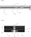
- a film type planar heating element for preventing electromagnetic waves is a film type planar heating element configured in a form of multiple layers of films to generate heat, the film type planar heating element comprising: a base film 10 having a sheet film shape and mounted on a floor; a carbon heating unit 20 made of carbon materials and arranged in multiple rows to generate heat planarly; a pair of center-adjacent copper foil busbars 30 closely disposed to each other and facing each other so that intensities of electromagnetic waves and magnetic field are mutually canceled each other when current is applied; a pair of center silver busbars 40 made of silver materials allowing the applied current to smoothly flow to the carbon heating unit 20, and a Lamirex film 50 coated on a top side of the base film 10.
- the carbon heating unit 20 is made of carbon materials and arranged in multiple rows to generate heat planarly on the top side of the base film 10.
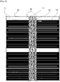
- the carbon heating unit 20 comprises a pair of busbar-carbon adhesion portions 21 which is formed by cutting the center of the carbon heating unit 20 and to which the pair of center-adjacent copper foil busbar 30 is adhered, an adhesion connection portion 22 extending to both sides of the busbar-carbon adhesion portions 21, a pair of upper connection portions 23 extending upward at outer ends of the adhesion connection portions 22, and a dual carbon heating unit 24 configured in such a way that two of the carbon heating units 20 are interconnected through the upper connection portions 23.
- a surface of a center area of the dual carbon heating unit 24 of the carbon heating unit 20 is coated with an insulating coating portion 25 to be insulated from the center-adjacent copper foil busbar 30.
- the pair of center-adjacent copper foil busbars 30 applies current to the carbon heating unit 20 in the center area of the base film 10.
- the center-adjacent copper foil busbars 30 are closely arranged to each other and face each other so that intensities of electromagnetic waves and magnetic field are mutually canceled each other when the current is applied.
- the pair of center silver busbars 40 is formed between the carbon heating unit 20 and the center-adjacent copper foil busbars 30 and made of silver materials so that the current, which is applied to the copper foil busbars 30, can smoothly flow to the carbon heating unit 20.
- the Lamirex film 50 is coated on the top side of the base film 10 to protect the carbon heating unit 20, the center-adjacent copper foil busbars 30, and the center silver busbars 40.
- a middle-adjacent copper foil busbar 31 is formed between the pair of center-adjacent copper foil busbars 30 in the vicinity of the 30 center-adjacent copper foil busbars 30 to mutually cancel intensities of electromagnetic waves and magnetic field when the current is applied and to connect voltage generated in the pair of center-adjacent copper foil busbars 30 to the ground.
- the base film 10 made of synthetic resin materials is formed in a sheet film shape and mounted on a floor, and the carbon heating unit 20 made of carbon materials is arranged in multiple rows to generate heat planarly on the top side of the base film 10.
- the pair of center-adjacent copper foil busbars 30 is located in a center portion of the carbon heating unit 20, and the center-adjacent copper foil busbars 30 are closely disposed to each other and face each other so that intensities of electromagnetic waves and magnetic field are mutually canceled each other when current is applied.
- the pair of center silver busbars 40 made of silver materials is coated on the bottom side of the center-adjacent copper foil busbars 30 so that the applied current can smoothly flow to the carbon heating unit 20.
- the Lamirex film 50 is coated on the top side of the base film 10.
- the carbon heating unit 20 is made of carbon materials and arranged in multiple rows to generate heat planarly on the top side of the base film 10.
- the carbon heating unit 20 comprises a pair of busbar-carbon adhesion portions 21 which is formed by cutting the center of the carbon heating unit 20 and to which the pair of center-adjacent copper foil busbar 30 is adhered.
- the adhesion connection portion 22 extends to both sides of the busbar-carbon adhesion portions 21, and the pair of upper connection portions 23 extends upward at the outer ends of the adhesion connection portions 22.
- the dual carbon heating unit 24 configured to have two of the carbon heating units 20, which are interconnected to each other, is formed between the upper connection portions 23. Accordingly, this configuration of the dual carbon heating unit 24 enables the carbon heating unit 20 to be easily formed in a large area, and significantly improves heating efficiency by allowing the current to be applied from the center to both sides of the carbon heating portion 20 to generate heat.
- the pair of center-adjacent copper foil busbars 30 applies current to the carbon heating unit 20 in the center area of the base film 10 to allow the carbon heating unit 20 to generate heat.
- intensities of electromagnetic waves and magnetic field can be canceled when the current is applied.
- the film type planar heating element can be used safely without concerns regarding electromagnetic waves.
- the pair of center silver busbars 40 formed between the carbon heating unit 20 and the center-adjacent copper foil busbars 30 and made of silver materials, allows the current, which is applied to the copper foil busbars 30, to smoothly flow to the carbon heating unit 20. Accordingly, the film type planar heating element can be used safely for long periods of time.
- the middle-adjacent copper foil busbar 31 between the pair of center-adjacent copper foil busbars 30 in the vicinity of the center-adjacent copper foil busbars 30, intensities of electromagnetic waves and magnetic field can be canceled when the current is applied. Specifically, when the current is applied, multiple currents flow in the vicinity, and thus, intensities of electromagnetic waves and magnetic field are mutually canceled each other. Accordingly, the film type planar heating element can prevent generating electromagnetic waves.
- the middle-adjacent copper foil busbar 31 also can act as a ground by connecting voltage generated in the pair of center-adjacent copper foil busbars 30 to the ground.
- the Lamirex film 50 coated on the top side of the base film 10 to protect the carbon heating unit 20, the center-adjacent copper foil busbars 30, and the center silver busbars 40, allows the film type planar heating element to be conveniently used anywhere.
Landscapes
- Engineering & Computer Science (AREA)
- Microelectronics & Electronic Packaging (AREA)
- Physics & Mathematics (AREA)
- Thermal Sciences (AREA)
- Chemical & Material Sciences (AREA)
- Combustion & Propulsion (AREA)
- Mechanical Engineering (AREA)
- General Engineering & Computer Science (AREA)
- Surface Heating Bodies (AREA)
- Central Heating Systems (AREA)
- Resistance Heating (AREA)
Applications Claiming Priority (2)
| Application Number | Priority Date | Filing Date | Title |
|---|---|---|---|
| KR1020190090002A KR102075870B1 (ko) | 2019-07-25 | 2019-07-25 | 전자파 방지용 필름면상발열체 |
| PCT/KR2020/009123 WO2021015470A1 (fr) | 2019-07-25 | 2020-07-10 | Élément chauffant plan de type film permettant d'empêcher des ondes électromagnétiques |
Publications (4)
| Publication Number | Publication Date |
|---|---|
| EP4007447A1 true EP4007447A1 (fr) | 2022-06-01 |
| EP4007447A4 EP4007447A4 (fr) | 2022-08-31 |
| EP4007447B1 EP4007447B1 (fr) | 2024-08-28 |
| EP4007447C0 EP4007447C0 (fr) | 2024-08-28 |
Family
ID=70003741
Family Applications (1)
| Application Number | Title | Priority Date | Filing Date |
|---|---|---|---|
| EP20843244.3A Active EP4007447B1 (fr) | 2019-07-25 | 2020-07-10 | Élément chauffant plan de type film permettant d'empêcher des ondes électromagnétiques |
Country Status (5)
| Country | Link |
|---|---|
| US (1) | US12313267B2 (fr) |
| EP (1) | EP4007447B1 (fr) |
| KR (1) | KR102075870B1 (fr) |
| CN (1) | CN114097303B (fr) |
| WO (1) | WO2021015470A1 (fr) |
Families Citing this family (2)
| Publication number | Priority date | Publication date | Assignee | Title |
|---|---|---|---|---|
| KR102075870B1 (ko) * | 2019-07-25 | 2020-03-17 | (주)아이알테크니카 | 전자파 방지용 필름면상발열체 |
| CN113665232B (zh) * | 2021-08-23 | 2022-09-02 | 包头市山川圣阳热能科技有限公司 | 一种银浆丝网印刷版、电热膜制作方法及电热膜 |
Family Cites Families (19)
| Publication number | Priority date | Publication date | Assignee | Title |
|---|---|---|---|---|
| JPH10223358A (ja) * | 1997-02-05 | 1998-08-21 | Zojirushi Corp | 電気湯沸かし器のヒータ |
| KR100468651B1 (ko) * | 2003-04-14 | 2005-01-27 | 김태원 | 필름 히터 전기 보일러 |
| KR100618162B1 (ko) * | 2004-09-20 | 2006-08-29 | 김태원 | 필름보일러 및 그 제작방법 |
| CN200994198Y (zh) * | 2006-01-06 | 2007-12-19 | 李锡烔 | 采暖用发热板 |
| KR100682571B1 (ko) * | 2006-05-30 | 2007-02-16 | 주식회사 디에스티 | 전자파 상쇄 면상발열체 |
| CN100588299C (zh) * | 2006-06-27 | 2010-02-03 | 黄喆官 | 利用碳纤维制备多功能发热纸的方法 |
| KR20090121720A (ko) * | 2008-05-22 | 2009-11-26 | 김태원 | 카본 발열체를 이용한 전기온돌판넬 |
| KR101102041B1 (ko) * | 2011-09-21 | 2012-01-04 | 영창전지(주) | 온열매트 |
| CN202551374U (zh) * | 2012-03-15 | 2012-11-21 | 江苏米阳碳晶科技有限公司 | 一种低辐射碳晶电热板 |
| CN202873096U (zh) * | 2012-06-21 | 2013-04-10 | 王晓新 | 一种新型的电热膜 |
| CN103712410B (zh) * | 2012-09-28 | 2017-05-17 | Lg电子株式会社 | 电器产品 |
| CN104125665A (zh) * | 2013-04-27 | 2014-10-29 | 申成吉 | 碳纤维发热丝及发热织物和其制法及应用 |
| CN103298171B (zh) * | 2013-05-22 | 2016-03-30 | 深圳市卓先实业有限公司 | 无电磁辐射的发热板 |
| CN203387699U (zh) * | 2013-05-22 | 2014-01-08 | 深圳市卓先实业有限公司 | 无电磁辐射的发热板 |
| CN203708517U (zh) * | 2014-03-06 | 2014-07-09 | 柳宗辰 | 电磁自屏蔽式电热膜 |
| JP2016091884A (ja) * | 2014-11-07 | 2016-05-23 | 有限会社デジタルプランニングワークコア | 面状カーボンヒーターおよび面状カーボンヒーターの製造方法 |
| CN205283845U (zh) * | 2015-06-03 | 2016-06-01 | 陈树佳 | 一种平衡电流消磁发热膜 |
| CN206629287U (zh) * | 2017-04-05 | 2017-11-10 | 深圳市卓先实业有限公司 | 一种全方位无电磁辐射的发热板 |
| KR102075870B1 (ko) * | 2019-07-25 | 2020-03-17 | (주)아이알테크니카 | 전자파 방지용 필름면상발열체 |
-
2019
- 2019-07-25 KR KR1020190090002A patent/KR102075870B1/ko active Active
-
2020
- 2020-07-10 CN CN202080050523.0A patent/CN114097303B/zh active Active
- 2020-07-10 US US17/626,177 patent/US12313267B2/en active Active
- 2020-07-10 EP EP20843244.3A patent/EP4007447B1/fr active Active
- 2020-07-10 WO PCT/KR2020/009123 patent/WO2021015470A1/fr not_active Ceased
Also Published As
| Publication number | Publication date |
|---|---|
| KR102075870B1 (ko) | 2020-03-17 |
| CN114097303A (zh) | 2022-02-25 |
| CN114097303B (zh) | 2024-06-28 |
| EP4007447B1 (fr) | 2024-08-28 |
| US12313267B2 (en) | 2025-05-27 |
| WO2021015470A1 (fr) | 2021-01-28 |
| US20220243927A1 (en) | 2022-08-04 |
| EP4007447C0 (fr) | 2024-08-28 |
| EP4007447A4 (fr) | 2022-08-31 |
Similar Documents
| Publication | Publication Date | Title |
|---|---|---|
| KR20240041872A (ko) | Ttfield를 인가하기 위한 그라파이트의 시트를 포함하는 전극 어셈블리 | |
| JP4406899B2 (ja) | 医療用電極 | |
| EP4007447B1 (fr) | Élément chauffant plan de type film permettant d'empêcher des ondes électromagnétiques | |
| US20110315672A1 (en) | Infrared Heating Panels, Systems and Methods | |
| EA201291454A1 (ru) | Композитное оконное стекло с электрически нагреваемым покрытием | |
| CN111301247A (zh) | 片型加热元件和包括该片型加热元件的车门的扶手 | |
| CN106536244A (zh) | 辐射加热器装置 | |
| AU2018253549A1 (en) | Multilayered Electromagnetic Assembly | |
| CA2841497C (fr) | Panneaux chauffants a infrarouge avec distribution de chaleur non lineaire | |
| AU3838693A (en) | Energy dissipation resistor for implantable defibrillator | |
| RU2791281C1 (ru) | Плоский нагревательный элемент пленочного типа для предотвращения электромагнитных волн | |
| KR101376107B1 (ko) | 발열 온도 분포가 균일하고 습기방지 기능을 갖는 플란히터 | |
| KR100682571B1 (ko) | 전자파 상쇄 면상발열체 | |
| KR20100129260A (ko) | 면상발열체 및 면상발열체 제조 방법 | |
| KR20080003382U (ko) | 면상발열체 | |
| KR101559087B1 (ko) | 전열패널 및 그 전열패널의 전자파 차폐방법 | |
| JP3227292U (ja) | 電気刺激装置に電極増益効果をもたらす配線構造 | |
| JP3354105B2 (ja) | 面状発熱体 | |
| NL2036496B1 (en) | Heatable decorative panel system and heatable panel | |
| JP2564047Y2 (ja) | 低電圧で発熱する面状発熱体 | |
| KR200424357Y1 (ko) | 전자파 상쇄 면상발열체 | |
| JP2005044764A (ja) | 面状発熱体 | |
| JP3094482U (ja) | 面状発熱体 | |
| KR20060072888A (ko) | 전자파 차단 기능의 면상 발열체 | |
| DK1899655T3 (en) | Surface heating system for floor panels |
Legal Events
| Date | Code | Title | Description |
|---|---|---|---|
| STAA | Information on the status of an ep patent application or granted ep patent |
Free format text: STATUS: THE INTERNATIONAL PUBLICATION HAS BEEN MADE |
|
| PUAI | Public reference made under article 153(3) epc to a published international application that has entered the european phase |
Free format text: ORIGINAL CODE: 0009012 |
|
| STAA | Information on the status of an ep patent application or granted ep patent |
Free format text: STATUS: REQUEST FOR EXAMINATION WAS MADE |
|
| 17P | Request for examination filed |
Effective date: 20220112 |
|
| AK | Designated contracting states |
Kind code of ref document: A1 Designated state(s): AL AT BE BG CH CY CZ DE DK EE ES FI FR GB GR HR HU IE IS IT LI LT LU LV MC MK MT NL NO PL PT RO RS SE SI SK SM TR |
|
| A4 | Supplementary search report drawn up and despatched |
Effective date: 20220802 |
|
| RIC1 | Information provided on ipc code assigned before grant |
Ipc: H05B 3/34 20060101ALI20220727BHEP Ipc: H05K 9/00 20060101ALI20220727BHEP Ipc: H05B 3/03 20060101ALI20220727BHEP Ipc: H05B 3/14 20060101ALI20220727BHEP Ipc: H05B 3/20 20060101AFI20220727BHEP |
|
| DAV | Request for validation of the european patent (deleted) | ||
| DAX | Request for extension of the european patent (deleted) | ||
| GRAP | Despatch of communication of intention to grant a patent |
Free format text: ORIGINAL CODE: EPIDOSNIGR1 |
|
| STAA | Information on the status of an ep patent application or granted ep patent |
Free format text: STATUS: GRANT OF PATENT IS INTENDED |
|
| INTG | Intention to grant announced |
Effective date: 20240529 |
|
| GRAS | Grant fee paid |
Free format text: ORIGINAL CODE: EPIDOSNIGR3 |
|
| GRAA | (expected) grant |
Free format text: ORIGINAL CODE: 0009210 |
|
| STAA | Information on the status of an ep patent application or granted ep patent |
Free format text: STATUS: THE PATENT HAS BEEN GRANTED |
|
| AK | Designated contracting states |
Kind code of ref document: B1 Designated state(s): AL AT BE BG CH CY CZ DE DK EE ES FI FR GB GR HR HU IE IS IT LI LT LU LV MC MK MT NL NO PL PT RO RS SE SI SK SM TR |
|
| REG | Reference to a national code |
Ref country code: CH Ref legal event code: EP |
|
| REG | Reference to a national code |
Ref country code: DE Ref legal event code: R096 Ref document number: 602020036832 Country of ref document: DE |
|
| REG | Reference to a national code |
Ref country code: IE Ref legal event code: FG4D |
|
| U01 | Request for unitary effect filed |
Effective date: 20240926 |
|
| U07 | Unitary effect registered |
Designated state(s): AT BE BG DE DK EE FI FR IT LT LU LV MT NL PT RO SE SI Effective date: 20241112 |
|
| PG25 | Lapsed in a contracting state [announced via postgrant information from national office to epo] |
Ref country code: NO Free format text: LAPSE BECAUSE OF FAILURE TO SUBMIT A TRANSLATION OF THE DESCRIPTION OR TO PAY THE FEE WITHIN THE PRESCRIBED TIME-LIMIT Effective date: 20241128 |
|
| PG25 | Lapsed in a contracting state [announced via postgrant information from national office to epo] |
Ref country code: PL Free format text: LAPSE BECAUSE OF FAILURE TO SUBMIT A TRANSLATION OF THE DESCRIPTION OR TO PAY THE FEE WITHIN THE PRESCRIBED TIME-LIMIT Effective date: 20240828 Ref country code: GR Free format text: LAPSE BECAUSE OF FAILURE TO SUBMIT A TRANSLATION OF THE DESCRIPTION OR TO PAY THE FEE WITHIN THE PRESCRIBED TIME-LIMIT Effective date: 20241129 |
|
| PG25 | Lapsed in a contracting state [announced via postgrant information from national office to epo] |
Ref country code: IS Free format text: LAPSE BECAUSE OF FAILURE TO SUBMIT A TRANSLATION OF THE DESCRIPTION OR TO PAY THE FEE WITHIN THE PRESCRIBED TIME-LIMIT Effective date: 20241228 |
|
| PG25 | Lapsed in a contracting state [announced via postgrant information from national office to epo] |
Ref country code: HR Free format text: LAPSE BECAUSE OF FAILURE TO SUBMIT A TRANSLATION OF THE DESCRIPTION OR TO PAY THE FEE WITHIN THE PRESCRIBED TIME-LIMIT Effective date: 20240828 |
|
| PG25 | Lapsed in a contracting state [announced via postgrant information from national office to epo] |
Ref country code: RS Free format text: LAPSE BECAUSE OF FAILURE TO SUBMIT A TRANSLATION OF THE DESCRIPTION OR TO PAY THE FEE WITHIN THE PRESCRIBED TIME-LIMIT Effective date: 20241128 Ref country code: ES Free format text: LAPSE BECAUSE OF FAILURE TO SUBMIT A TRANSLATION OF THE DESCRIPTION OR TO PAY THE FEE WITHIN THE PRESCRIBED TIME-LIMIT Effective date: 20240828 |
|
| PG25 | Lapsed in a contracting state [announced via postgrant information from national office to epo] |
Ref country code: RS Free format text: LAPSE BECAUSE OF FAILURE TO SUBMIT A TRANSLATION OF THE DESCRIPTION OR TO PAY THE FEE WITHIN THE PRESCRIBED TIME-LIMIT Effective date: 20241128 Ref country code: PL Free format text: LAPSE BECAUSE OF FAILURE TO SUBMIT A TRANSLATION OF THE DESCRIPTION OR TO PAY THE FEE WITHIN THE PRESCRIBED TIME-LIMIT Effective date: 20240828 Ref country code: NO Free format text: LAPSE BECAUSE OF FAILURE TO SUBMIT A TRANSLATION OF THE DESCRIPTION OR TO PAY THE FEE WITHIN THE PRESCRIBED TIME-LIMIT Effective date: 20241128 Ref country code: IS Free format text: LAPSE BECAUSE OF FAILURE TO SUBMIT A TRANSLATION OF THE DESCRIPTION OR TO PAY THE FEE WITHIN THE PRESCRIBED TIME-LIMIT Effective date: 20241228 Ref country code: HR Free format text: LAPSE BECAUSE OF FAILURE TO SUBMIT A TRANSLATION OF THE DESCRIPTION OR TO PAY THE FEE WITHIN THE PRESCRIBED TIME-LIMIT Effective date: 20240828 Ref country code: GR Free format text: LAPSE BECAUSE OF FAILURE TO SUBMIT A TRANSLATION OF THE DESCRIPTION OR TO PAY THE FEE WITHIN THE PRESCRIBED TIME-LIMIT Effective date: 20241129 Ref country code: ES Free format text: LAPSE BECAUSE OF FAILURE TO SUBMIT A TRANSLATION OF THE DESCRIPTION OR TO PAY THE FEE WITHIN THE PRESCRIBED TIME-LIMIT Effective date: 20240828 |
|
| PG25 | Lapsed in a contracting state [announced via postgrant information from national office to epo] |
Ref country code: SM Free format text: LAPSE BECAUSE OF FAILURE TO SUBMIT A TRANSLATION OF THE DESCRIPTION OR TO PAY THE FEE WITHIN THE PRESCRIBED TIME-LIMIT Effective date: 20240828 |
|
| PG25 | Lapsed in a contracting state [announced via postgrant information from national office to epo] |
Ref country code: CZ Free format text: LAPSE BECAUSE OF FAILURE TO SUBMIT A TRANSLATION OF THE DESCRIPTION OR TO PAY THE FEE WITHIN THE PRESCRIBED TIME-LIMIT Effective date: 20240828 |
|
| PG25 | Lapsed in a contracting state [announced via postgrant information from national office to epo] |
Ref country code: SK Free format text: LAPSE BECAUSE OF FAILURE TO SUBMIT A TRANSLATION OF THE DESCRIPTION OR TO PAY THE FEE WITHIN THE PRESCRIBED TIME-LIMIT Effective date: 20240828 |
|
| PLBE | No opposition filed within time limit |
Free format text: ORIGINAL CODE: 0009261 |
|
| STAA | Information on the status of an ep patent application or granted ep patent |
Free format text: STATUS: NO OPPOSITION FILED WITHIN TIME LIMIT |
|
| U20 | Renewal fee for the european patent with unitary effect paid |
Year of fee payment: 6 Effective date: 20250626 |
|
| 26N | No opposition filed |
Effective date: 20250530 |
|
| REG | Reference to a national code |
Ref country code: CH Ref legal event code: H13 Free format text: ST27 STATUS EVENT CODE: U-0-0-H10-H13 (AS PROVIDED BY THE NATIONAL OFFICE) Effective date: 20260224 |
|
| GBPC | Gb: european patent ceased through non-payment of renewal fee |
Effective date: 20250710 |
|
| PG25 | Lapsed in a contracting state [announced via postgrant information from national office to epo] |
Ref country code: GB Free format text: LAPSE BECAUSE OF NON-PAYMENT OF DUE FEES Effective date: 20250710 |
|
| PG25 | Lapsed in a contracting state [announced via postgrant information from national office to epo] |
Ref country code: CH Free format text: LAPSE BECAUSE OF NON-PAYMENT OF DUE FEES Effective date: 20250731 |