EP4007452B1 - Dispositif de décongélation par micro-ondes ou par radiofréquences distribuées - Google Patents
Dispositif de décongélation par micro-ondes ou par radiofréquences distribuées Download PDFInfo
- Publication number
- EP4007452B1 EP4007452B1 EP20857677.7A EP20857677A EP4007452B1 EP 4007452 B1 EP4007452 B1 EP 4007452B1 EP 20857677 A EP20857677 A EP 20857677A EP 4007452 B1 EP4007452 B1 EP 4007452B1
- Authority
- EP
- European Patent Office
- Prior art keywords
- antenna
- thawing
- radio frequency
- power
- unit
- Prior art date
- Legal status (The legal status is an assumption and is not a legal conclusion. Google has not performed a legal analysis and makes no representation as to the accuracy of the status listed.)
- Active
Links
Images


Classifications
-
- H—ELECTRICITY
- H05—ELECTRIC TECHNIQUES NOT OTHERWISE PROVIDED FOR
- H05B—ELECTRIC HEATING; ELECTRIC LIGHT SOURCES NOT OTHERWISE PROVIDED FOR; CIRCUIT ARRANGEMENTS FOR ELECTRIC LIGHT SOURCES, IN GENERAL
- H05B6/00—Heating by electric, magnetic or electromagnetic fields
- H05B6/64—Heating using microwaves
- H05B6/66—Circuits
- H05B6/68—Circuits for monitoring or control
- H05B6/688—Circuits for monitoring or control for thawing
-
- H—ELECTRICITY
- H05—ELECTRIC TECHNIQUES NOT OTHERWISE PROVIDED FOR
- H05B—ELECTRIC HEATING; ELECTRIC LIGHT SOURCES NOT OTHERWISE PROVIDED FOR; CIRCUIT ARRANGEMENTS FOR ELECTRIC LIGHT SOURCES, IN GENERAL
- H05B6/00—Heating by electric, magnetic or electromagnetic fields
- H05B6/64—Heating using microwaves
- H05B6/70—Feed lines
- H05B6/707—Feed lines using waveguides
-
- H—ELECTRICITY
- H05—ELECTRIC TECHNIQUES NOT OTHERWISE PROVIDED FOR
- H05B—ELECTRIC HEATING; ELECTRIC LIGHT SOURCES NOT OTHERWISE PROVIDED FOR; CIRCUIT ARRANGEMENTS FOR ELECTRIC LIGHT SOURCES, IN GENERAL
- H05B6/00—Heating by electric, magnetic or electromagnetic fields
- H05B6/64—Heating using microwaves
- H05B6/72—Radiators or antennas
-
- H—ELECTRICITY
- H05—ELECTRIC TECHNIQUES NOT OTHERWISE PROVIDED FOR
- H05B—ELECTRIC HEATING; ELECTRIC LIGHT SOURCES NOT OTHERWISE PROVIDED FOR; CIRCUIT ARRANGEMENTS FOR ELECTRIC LIGHT SOURCES, IN GENERAL
- H05B6/00—Heating by electric, magnetic or electromagnetic fields
- H05B6/64—Heating using microwaves
- H05B6/78—Arrangements for continuous movement of material
- H05B6/782—Arrangements for continuous movement of material wherein the material moved is food
-
- H—ELECTRICITY
- H05—ELECTRIC TECHNIQUES NOT OTHERWISE PROVIDED FOR
- H05B—ELECTRIC HEATING; ELECTRIC LIGHT SOURCES NOT OTHERWISE PROVIDED FOR; CIRCUIT ARRANGEMENTS FOR ELECTRIC LIGHT SOURCES, IN GENERAL
- H05B6/00—Heating by electric, magnetic or electromagnetic fields
- H05B6/64—Heating using microwaves
- H05B6/80—Apparatus for specific applications
Definitions
- the present invention relates to the technical field of thawing, in particular to a distributed radio frequency or microwave thawing device.
- Radio frequency or microwave thawing is a new type of thawing method, which makes lattice, molecules and ions in articles to be thawed vibrate and rotate violently through the high-speed changing radio frequency or microwave oscillating electromagnetic field to heat up, so as to achieve the purpose of rapid thawing.
- the radio frequency or microwave thawing is faster, heat evenly and has less impact on a quality of the articles to be thawed.
- the Chinese patent document published as CN208768875U discloses a radio frequency thawing apparatus, including a casing, where an interior of the casing is divided into a radio frequency space and an accommodating space from top to bottom by a baffle; and an air inlet is disposed on a side wall of the accommodating space, and an air outlet is disposed on a top of the radio frequency space. It also includes a food raw material box, a radio frequency heating mechanism for heating and thawing frozen food in the food raw material box, and a hot air system arranged in the accommodating space and communicated with the interior of the food raw material box.
- the radio frequency heating mechanism includes a radio frequency generator disposed in the accommodation space, an upper plate and a lower plate relatively disposed in the radio frequency space from top to bottom.
- the radio frequency generator is respectively connected to the upper plate and the lower plate, and an alternating electric field is formed between the upper plate and the lower plate after being electrified; and the food raw material box is located between the upper plate and the lower plate.
- the radio frequency thawing apparatus provided by the solution only provides one pair of antennas in the radio frequency space, and when the apparatus is required to provide high power, the power loss will increase accordingly. Moreover, since only one pair of antennas are adopted, the power densities at different positions on the antenna board are different, and the power density far away from the power-up position is small, resulting in the problem of uneven power density.
- JP2009259511A discloses a microwave processor which includes a heating chamber housing the workpiece, oscillating units, power distributing units, phase variable units, power amplifying units, power supply switching units, power supply units which are arranged on the wall surface of the heating chamber and receive microwaves outputted from microwave generating units to emit the microwaves into heating chamber, and power detecting units which detect power reflected from the power supply units to the power amplifying units.
- the power supply switching units select a power supply unit capable of emitting microwaves most efficiently to the workpiece out of the power supply units to cause the selected power supply unit to emit microwaves.
- CN109452530A discloses a switch matching module and thawing apparatus with two radiation mechanisms.
- EP3324705A1 discloses a solid-state heating system.
- JP2009032638A discloses a microwave processing device.
- WO2014/191799A1 discloses a radio frequency apparatus for thawing food products, through the use of an oscillating electromagnetic field, which comprises a continuous conveyor belt, on which the food products are positioned, elements for supporting and for moving the conveyor belt forward, an inlet section, for the introduction of the food products to be thawed, a central section, defining a tunnel in which the food products are thawed, an outlet section, from which the thawed food products come out, at least one oscillating voltage generator, for generating the oscillating electromagnetic field, and elements for washing and/or sanitizing the conveyor belt and/or the inlet section and/or the central section and/or the outlet section.
- CN107373296A discloses a uniform-unfreezing type radio frequency heating deice which comprises a radio frequency heater, a medium vessel and a heat exchanger, wherein the medium vessel which is full of a medium solution is arranged between two polar plates of the radio heater; an opening is formed in the upper end of the medium vessel; an object to be unfrozen is dipped into the medium vessel to be unfrozen through the radio frequency heater.
- an object of the present invention is to provide a distributed radio frequency or microwave thawing device.
- the distributed radio frequency or microwave thawing device includes one or more thawing units
- the working bin includes a first support plate and a second support plate, the first support plate is disposed adjacent to the first antenna group, the second support plate is disposed adjacent to the second antenna group, and a space for placing the article to be thawed is formed between the first support plate and the second support plate;
- the thawing unit further comprises a tuning module, the tuning module comprises one or more passive devices; radio frequency or microwave power generated by the radio frequency or microwave generation module enters the tuning module via the measuring unit for impedance matching and then reaches the first antenna group and the second antenna group respectively, wherein an alternating electric field is formed between the first antenna group and the second antenna group; the measuring unit is configured to detect forward power and backward power of the radio frequency or microwave generation module; and the tuning module is configured to adjust to an impedance matching state where a ratio of the backward power to the forward power is minimized; the control unit is configured to calculate the ratio of the backward power to the forward power according to the forward power and the backward power fed back by the measuring unit, and determine a state of the tuning module; the tuning module has an automatic mode, and the tuning module in the automatic mode automatically controls the impedance matching state between the output end of the radio frequency or microwave generation module and the input end of the antenna unit through the control unit, and the control unit adjusts the tuning module according to the forward power and the backward power fed
- the control unit is further configured to determine whether the thawing unit is in empty state according to the state of the tuning module and, if the thawing unit is detected to be in the empty state, to adjust the radio frequency or microwave power output by the radio frequency or microwave generation module, respectively, such that output power automatically decreases to minimum in the empty state.
- the radio frequency or microwave generation module includes a radio frequency or microwave generation source and a solid-state power amplifier.
- the distributed radio frequency or microwave thawing device also includes a conveying means, a feeding port, a discharging port and a main console;
- balanced feeding is adopted to ensure that feeding points of the first antenna in the first antenna group have a voltage amplitude difference less than 50% and a phase difference within a range of 0-90°; feeding points of the second antenna in the second antenna group have a voltage amplitude difference less than 50% and a phase difference within a range of 0-90°; and feeding points of the first antenna and the second antenna of the antenna unit have a voltage amplitude difference less than 70% and a phase difference within a range of 80-280°.
- the present invention has the following beneficial effects:
- orientation or positional relationships indicated by terms such as “up”, “down”, “front”, “rear”, “left”, “right”, “vertical”, “horizontal”, “top”, “bottom”, “in” and “out” are based on the orientation or positional relationships shown in the drawings, for ease of description of the present application and simplification of the description only, these terms do not indicate or imply that the means or element referred to must have a specific orientation or be constructed and operated in a specific orientation, and therefore cannot be construed as limitations to the present application.
- the distributed radio frequency or microwave thawing device can arrange a plurality of antenna units in the thawing chamber of each thawing unit, each antenna unit radiates corresponding power, which does not require combining the antenna units prior to generating the high power, and ensures the power density unchanged at the same time.
- Size and power of the traditional thawing unit are large (at least 2 KW), and the size and power design of a combined thawing device are inflexible and the cost is high, which can not better meet the needs of users.
- the distributed radio frequency or microwave thawing device provided by the present invention has the advantages of small size of each thawing unit, moderate power and various choices. If the traditional thawing device breaks down, it can't be used, resulting in the construction period delayed and high maintenance cost.
- the distributed radio frequency or microwave thawing device provided by the present invention adopts a combination mode of distributed building blocks to construct the thawing device, which features flexible location and diversity in function selection, and that if a certain thawing unit fails, the device can still continue to run, and at the same time, the maintenance is simple and the cost is low.
- the distributed radio frequency or microwave thawing device provided by the present invention is flexible in control, allows a flexibly selection of thawing units required for working, and makes it possible for flexibly setting the power of each thawing unit to ensure that the article to be thawed is in an optimal thawing state.
- the distributed radio frequency or microwave thawing device includes one or more thawing units.
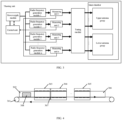
- the thawing unit includes a power supply module, a control unit, a radio frequency or microwave generation module, a measuring unit, an antenna means and a thawing chamber 105.
- the power supply module, the radio frequency or microwave generation module, the measuring unit and the antenna means are connected in sequence.
- the control unit is connected to the power supply module and the measuring unit, respectively.
- the antenna means is disposed in the thawing chamber 105, and the antenna means includes a first antenna group 101 and a second antenna group 102, the first antenna group 101 includes one or more first antennas, the second antenna group 102 includes one or more second antennas, the first antennas and the second antennas are arranged in pairs, pairs of first antenna and second antenna are arranged in parallel and opposite to each other and form an antenna unit, a plurality of antenna units are arranged side by side, and the thawing chamber 105 includes one or more rows of antenna units.
- a working bin 106 is formed between the first antenna group 101 and the second antenna group 102.
- the number of each of the radio frequency or microwave generation module and the measuring unit is one or more.
- the radio frequency or microwave generation module and the measuring unit are connected to the antenna units one to one.
- the radio frequency or microwave power generated by the radio frequency or microwave generation module reaches the first antenna group 101 and the second antenna group 102, and an alternating electric field is formed between the first antenna group 101 and the second antenna group 102.
- the first antenna group 101 and the second antenna group 102 include a metal plate antenna and/or a waveguide antenna with a gap between adjacent antenna units.
- a distance between the first antenna group 101 and the second antenna group 102 can be adjusted according to a shape and a size of an article to be thawed 308.
- the first antenna group 101 and the second antenna group 102 are waveguide antennas
- the first antenna group 101 includes one or more first waveguide antennas 201
- the second antenna group 102 includes one or more second waveguide antennas.
- the working bin 106 includes a first support plate 104 and a second support plate 103, the first support plate 104 is disposed adjacent to the first antenna group 101, the second support plate 103 is disposed adjacent to the second antenna group 102, a space for placing an article to be thawed 308 is formed between the first support plate 104 and the second support plate 103.
- the first support plate 104 and the second support plate 103 are insulating support plates. A distance between the first support plate 104 and the second support plate 103 can be adjusted according to the shape and size of an article to be thawed 308.
- the thawing chamber 105 is a metal chamber, and the thawing chamber 105 is grounded, so as to prevent the radio frequency or microwave power from leaking to the outside of the chamber.
- the radio frequency or microwave generation module includes a radio frequency or microwave generation source and a solid-state power amplifier.
- the solid-state power amplifier can amplify radio frequency or microwave signals with small power to produce radio frequency or microwave energy capable for quick thawing, and devices such as LDMOS or GaN can be used generally.
- the solid-state power amplifier is used to amplify the radio frequency or microwave signal generated by the radio frequency or microwave generation module to appropriate power, and transfer this part of radio frequency or microwave power to the measuring unit.
- the thawing unit further includes a tuning module.
- the tuning module includes one or more passive devices.
- the radio frequency or microwave power generated by the radio frequency or microwave generation module enters the tuning module via the measuring unit for impedance matching and then reaches the first antenna group 101 and the second antenna group 102 respectively, forming an alternating electric field between the first antenna group 101 and the second antenna group 102.
- the passive device is a capacitor with an adjustable capacitance value.
- the passive device is a resistor with an adjustable resistance value.
- the passive device is an inductor with an adjustable inductance value.
- the measuring unit can detect forward power and backward power of the radio frequency or microwave generation module.
- the tuning module can adjust to an impedance matching state where a ratio of the backward power to the forward power is minimized, to ensure maximum radio frequency or microwave energy entering the working bin during thawing.
- the control unit can calculate the ratio of the backward power to the forward power according to the forward power and the backward power fed back by the measuring unit, and determine a state of the tuning module. If the ratio of the backward power to the forward power is smaller, it means that more radio frequency or microwave power reaches the antenna, and the thaw time is shorter.
- the tuning module has a manual mode and/or an automatic mode, and the tuning module in the manual mode adjusts the impedance matching state between an output end of the radio frequency or microwave generation module and an input end of the antenna unit through manual setting.
- the tuning module in the automatic mode automatically controls the impedance matching state between the output end of the radio frequency or microwave generation module and the input end of the antenna unit through the control unit, and the control unit adjusts the tuning module according to the forward power and the backward power fed back by the measuring unit.
- the state of the tuning module is unique and definite when the thawing unit is in an empty state, for example, when the article to be thawed 308 is not placed in the working bin 106. Therefore, the control unit can determine whether the thawing unit is in the empty state according to the state of the tuning module. When the thawing unit is detected to be in the empty state, the control unit will automatically adjust the radio frequency or microwave power output by the radio frequency or microwave generation module, so that the output power automatically decreases to the minimum in the empty state.
- Balanced feeding is adopted to ensure that feeding points of the first antenna in the first antenna group 101 have a voltage amplitude difference less than 50% and a phase difference within a range of 0-90°; feeding points of the second antenna in the second antenna group 102 have a voltage amplitude difference less than 50% and a phase difference within a range of 0-90°; and feeding points of the first antenna and the second antenna of the antenna unit have a voltage amplitude difference less than 70% and a phase difference within a range of 80-280°.
- the feed points of the first antenna in the first antenna group 101 have the same voltage amplitudes and phases
- the feed points of the second antenna in the second antenna group 102 have the same voltage amplitudes and phases
- the feed points of the first antenna and the second antenna of the antenna unit have the same voltage amplitudes and opposite phases, where the same may be exactly the same or approximately the same, as long as the two values are equivalent.
- the control unit, the measuring unit and the tuning module work together to realize the balanced feeding.
- a direction of the electric field is a direction in which the electric potential energy decreases most rapidly, and if the voltage amplitudes and phases on all the first antennas in the first antenna group 101 are approximately the same, the electric field between their edges is almost zero.
- the electric field between edges of the second antennas in the second antenna group 102 is almost zero.
- the voltage on the first antenna group 101 and the voltage on the second antenna group 102 are of the same amplitude and opposite phase, more electric fields can be formed between the two antenna groups to facilitate rapid thawing of food.
- the distributed radio frequency or microwave thawing device also includes a conveying means, a feeding port 302, a discharging port 306 and a main console.
- the conveying means includes a conveyor belt 301 and a drive means, and the drive means is configured to drive the conveyor belt 301 to move.
- Windows are disposed on the working bin 106 of the thawing unit, a plurality of thawing units are arranged side by side and connected to each other through the windows, and the windows are connected through a connecting channel 307 to form a conveying channel for the article to be thawed 308, the conveyor belt 301 is disposed in the conveying channel, and the antenna units are arranged side by side along a conveying direction of the conveying channel.
- the feeding port 302 and the discharging port 306 are arranged at two ends of the conveying channel, respectively.
- the feeding port 302 and the discharging port 306 are respectively a metal feeding port and a metal discharging port, and the connecting channel 307 is a metal connecting channel.
- the main console is in signal connection with control units of a plurality of thawing units. A user can independently select the number and placement of the thawing units according to needs, and can control the working state of each thawing unit separately through the main console, and adjust the working state of the thawing unit according to the thawing power and time required by the articles to be thawed.
- n is a natural number
- the conveyor belt 301 transports article to be thawed 308 by starting from the feeding port 302, passing through the first thawing unit 303, the second thawing unit 304 ... the last thawing unit (the n-th thawing unit 305), and reaching the discharging port 306 to complete thawing of the food.
- one or more rolling shafts 205 are provided inside the thawing chamber 105, and the rolling shafts 205 are connected to the conveyor belt 301, through which the conveyor belt 301 moves, and the rolling shafts 205 can reduce the frictional resistance when the conveyor belt moves.
- the distributed radio frequency or microwave thawing device includes one or more thawing units.
- the thawing unit includes a power supply module, a radio frequency or microwave generation module, a measuring unit, a tuning module, a control unit, an antenna means and a thawing chamber 105.
- the power supply module, the radio frequency or microwave generation module, the measuring unit, the tuning module and the antenna means are connected in sequence.
- the control unit is connected to the power supply module, the measuring unit and the tuning module, respectively.
- the power module is used for providing stable and reliable power output for each system module of the thawing unit.
- the radio frequency or microwave generation module is used for generating the radio frequency or microwave high power oscillating electromagnetic field, so that the lattice, molecules, ions and the like in the food violently oscillate and rotate to heat up, so as to achieve the purpose of thawing.
- the measuring unit is used for detecting the forward power and the backward power of the radio frequency or microwave generation module, thereby calculating the ratio of the backward power to the forward power. If the ratio is smaller, it means that more radio frequency or microwave power reaches the antenna and the thawing time is shorter.
- the tuning module is provided with one or more passive devices with adjustable inductance values or variable capacitance values, which can compensate for a ground impedance change caused by differences in type, size, location, shape and temperature of the food.
- the control unit takes charge of monitoring the working state of the whole system, collecting the forward power and backward power fed back by the measuring unit and adjusting the tuning module to ensure that the maximum radio frequency or microwave energy enters the thawing chamber 105 during thawing.
- the thawing chamber 105 includes an antenna means and a working bin 106.
- the antenna means includes a first antenna group 101 and a second antenna group 102, the first antenna group 101 includes one or more first antennas, the second antenna group 102 includes one or more second antennas, the first antennas and the second antennas are arranged in pairs, pairs of first antenna and second antenna are arranged in parallel and opposite to each other and form an antenna unit, a plurality of antenna units are arranged side by side, so that a relatively uniform electric field distribution can be easily realized between the first antenna and the second antenna which are arranged in parallel.
- the working bin 106 is formed between the first antenna group 101 and the second antenna group 102.
- the working bin 106 includes a first support plate 104 and a second support plate 103, the first support plate 104 is disposed adjacent to the first antenna group 101, the second support plate 103 is disposed adjacent to the second antenna group 102, a space for placing the article to be thawed 308 is formed between the first support plate 104 and the second support plate 103.
- the first support plate 104 and the second support plate 103 are insulating support plates.
- the thawing chamber 105 is a metal chamber so as to constitute a shielding chamber, and further, the thawing chamber 105 is connected to the earth so as to prevent radio frequency or microwave power from leaking to outside of the chamber.
- the present invention selectively arranges one or more antenna units in the thawing chamber 105, and the number of each of the radio frequency or microwave generation module and the measuring unit is one or more.
- the radio frequency or microwave generation module and the measuring unit are connected to the antenna units one to one.
- each antenna unit receives the radio frequency or microwave energy provided by one radio frequency or microwave generation module, which does not require combining the antenna units prior to generating the high power, thus avoiding the loss caused by power combining, and at the same time, the power density in the thawing chamber 105 can be improved, so that the thawing speed is faster and the safety is higher.
- the radio frequency or microwave power generated by the radio frequency or microwave generation module enters the tuning module via the measuring unit for impedance matching and then reaches the first antenna group 101 and the second antenna group 102 respectively, forming an alternating electric field between the first antenna group 101 and the second antenna group 102.
- a solid-state power amplifier is arranged between the radio frequency or microwave generation module and the antenna means.
- the solid-state power amplifier can amplify radio frequency or microwave signals with small power to produce radio frequency or microwave energy capable for quick thawing, and devices such as LDMOS or GaN can be used generally.
- the solid-state power amplifier is used to amplify the radio frequency or microwave signal generated by the radio frequency or microwave generation module to appropriate power, and transfer this part of radio frequency or microwave power to the measuring unit.
- the measuring unit can detect the forward power and the backward power of the radio frequency or microwave generation module, thereby calculating the ratio of the backward power to the forward power. If the ratio is smaller, it means that more radio frequency or microwave power reaches the antenna and the thawing time is shorter.
- the control unit adjusts the tuning module according to the forward power and the backward power fed back by the measuring unit.
- the tuning module includes one or more passive devices with adjustable inductance values or variable capacitance values. The tuning module can select an impedance matching state where a ratio of the backward power to the forward power is minimized, to ensure maximum radio frequency or microwave energy entering the working bin during thawing.
- the state of the tuning module is unique and definite in an empty state (i.e., no food is placed in the working bin 106), and the thawing unit can detect whether the tuning module is in the automatic state to determine whether it is in the empty state.
- the thawing unit detects that it is in an empty state, it will automatically adjust the power, that is, in the empty state, the output power can be automatically reduced to the minimum.
- a direction of the electric field is a direction in which the electric potential energy decreases most rapidly, and if the voltage amplitudes and phases on all the first antennas in the first antenna group 101 are approximately the same, the electric field between their edges is almost zero. Similarly, the electric field between edges of the second antennas in the second antenna group 102 is almost zero.
- the voltage on the first antenna group 101 and the voltage on the second antenna group 102 are of the same amplitude and opposite phase, more electric fields can be formed between the two antenna groups to facilitate rapid thawing of food.
- the feed points of the first antenna in the first antenna group 101 have the same voltage amplitudes and phases
- the feed points of the second antenna in the second antenna group 102 have the same voltage amplitudes and phases
- the feed points of the first antenna and the second antenna of the antenna unit have the same voltage amplitudes and opposite phases (i.e., 180° out of phase).
- Each antenna is provided with a low-power radio frequency or microwave signal.
- a plurality of thawing units are combined in a form of building blocks to construct the distributed radio frequency or microwave thawing device.
- the working bins 106 of the thawing units are opened to the left and right to facilitate the entry and exit of the article to be thawed 308 by passing the conveyor belt 301 through the working bin 106 of each thawing unit.
- the article to be thawed 308 is placed at the feeding port 302, which is an entry channel for food, and can play the role of attenuating electromagnetic waves to prevent overflow of the radio frequency or microwave energy.
- the conveyor carries food passing through each of the thawing units until reaching the discharging port 306 to complete the thawing of the food.
- the discharging port 306 also acts to attenuate electromagnetic waves to prevent the overflow of the radio frequency or microwave energy. Due to the small size and moderate power of each thawing unit, the assembled thawing device has flexible structure and low maintenance cost, and each thawing unit can be arranged separately to ensure that the food is in the optimal thawing state. At the same time, the article to be thawed 308 is placed on the conveyor belt and passes through each thawing unit sequentially, so that the thawing uniformity will be better.
- a metal feeding port is installed at one side of the first thawing unit 303
- a metal discharging port is installed at one side of the n-th thawing unit 305
- a metal connecting channel 307 is arranged between the thawing units, they all serve to prevent the overflow of the radio frequency or microwave energy.
- Users can choose the number of thawing units independently and arrange them independently, and can also set the working state (e.g., power) of each thawing unit when different items are thawed.
- the control units of the thawing units are all connected through electric signals of the main console, and the user can independently control the thawing units through the main console.
Landscapes
- Physics & Mathematics (AREA)
- Electromagnetism (AREA)
- Electric Ovens (AREA)
- Freezing, Cooling And Drying Of Foods (AREA)
- Control Of High-Frequency Heating Circuits (AREA)
- Constitution Of High-Frequency Heating (AREA)
Claims (4)
- Un dispositif de décongélation à micro-ondes ou radiofréquences distribué, comprenant une ou plusieurs unités de décongélation,dans lequel chacune des une ou plusieurs unités de décongélation comprend un module d'alimentation électrique, une unité de commande, un module de génération de radiofréquence ou micro-onde, une unité de mesure, un moyen d'antenne et une chambre de décongélation (105) ;le module d'alimentation électrique, le module de génération de radiofréquence ou micro-onde, l'unité de mesure et le moyen d'antenne sont raccordés en séquence ;l'unité de commande est raccordée au module d'alimentation électrique et à l'unité de mesure, respectivement ;le moyen d'antenne est placé dans la chambre de décongélation (105), et le moyen d'antenne comprend un premier groupe d'antennes (101) et un deuxième groupe d'antennes (102), le premier groupe d'antennes (101) comprend une ou plusieurs premières antennes, le deuxième groupe d'antennes (102) comprend une ou plusieurs deuxièmes antennes, les une ou plusieurs premières antennes et les une ou plusieurs deuxièmes antennes sont agencées en une ou plusieurs paires respectivement, la une ou plusieurs paires de premières et deuxièmes antennes forment une ou plusieurs unités d'antennes respectivement, dans lesquelles la première antenne et la deuxième antenne dans chaque unité d'antennes sont agencées en parallèle et de façon mutuellement opposée ; dans le cas de plus d'une unité d'antennes, une pluralité d'unités d'antennes sont agencées côte à côte, et la chambre de décongélation (105) comprend une ou plusieurs rangées d'unités d'antennes ;un bac de travail (106) est formé entre le premier groupe d'antennes (101) et le deuxième groupe d'antennes (102) ;le nombre de chacun des modules de génération de radiofréquence ou micro-onde et unités de mesure est de un ou plus ;le module de génération de radiofréquence ou micro-onde et l'unité de mesure sont raccordés un à un aux unités d'antennes ; le bac de travail (106) comprend une première plaque de support (104) et une deuxième plaque de support (103), et la chambre de décongélation (105) est une chambre en métal, et la chambre de décongélation (105) est mise à la masse ;la première plaque de support (104) est placée adjacente au premier groupe d'antennes (101), la deuxième plaque de support (103) est placée adjacente au deuxième groupe d'antennes (102), un espace pour placer un article à décongeler (308) est formé entre la première plaque de support (104) et la deuxième plaque de support (103) ; la première plaque de support (104) et la deuxième plaque de support (103) sont des plaques de support isolantes ; dans lequel l'unité de décongélation comprend en outre un module d'accordage, le module d'accordage comprend un ou plusieurs dispositifs passifs ; la radiofréquence ou puissance micro-onde générée par le module de génération de radiofréquence ou micro-onde pénètre le module d'accordage via l'unité de mesure pour correspondance d'impédance puis atteint le premier groupe d'antennes (101) et le deuxième groupe d'antennes (102) respectivement, dans lequel un champ électrique alternatif est formé entre le premier groupe d'antennes (101) et le deuxième groupe d'antennes (102) ; l'unité de mesure est configurée pour détecter la puissance directe et la puissance réfléchie du module de génération de radiofréquence ou micro-onde ; et le module d'accordage est configuré pour ajuster à un état de correspondance d'impédance où le rapport de la puissance réfléchie à la puissance directe est minimisé ; l'unité de commande est configurée pour calculer le rapport de la puissance réfléchie à la puissance directe en fonction de la puissance directe et de la puissance réfléchie renvoyée par l'unité de mesure, et détermine un état du module d'accordage ; le module d'accordage dispose d'un mode automatique, et le module d'accordage en mode automatique contrôle automatiquement l'état de correspondance d'impédance entre l'extrémité de sortie du module de génération de radiofréquence ou micro-onde et l'extrémité d'entrée de l'unité d'antenne via l'unité de commande, et l'unité de commande ajuste le module d'accordage en fonction de la puissance directe et de la puissance réfléchie renvoyées par l'unité de mesure ; caractérisé en ce quela distance entre la première plaque de support (104) et la deuxième plaque de support (103) est ajustable en fonction de la forme et de la taille de l'article à décongeler (308),dans lequel l'unité de commande est en outre configurée pour déterminer si l'unité de décongélation est à l'état vide en fonction de l'état du module d'accordage et, s'il est détecté que l'unité de décongélation est à l'état vide, pour ajuster la puissance de sortie de radiofréquence ou micro-onde par le module de génération de radiofréquence ou micro-onde, respectivement, de sorte que la puissance de sortie décroît automatiquement jusqu'au minimum à l'état vide.
- Un dispositif de décongélation à micro-ondes ou radiofréquences distribué selon la revendication 1, caractérisé en ce que le module de génération de radiofréquence ou micro-onde comprend une source de génération de radiofréquence ou micro-onde et un amplificateur de puissance à semi-conducteurs.
- Un dispositif de décongélation à micro-ondes ou radiofréquences distribué selon la revendication 1, comprenant en outre un moyen d'acheminement, un orifice d'alimentation (302), un orifice d'évacuation (306) et une console principale ; caractérisé en ce quele moyen d'acheminement comprend une bande transporteuse (301) et un moyen d'entraînement, et le moyen d'entraînement est configuré pour entraîner le déplacement de la bande transporteuse (301) ;des fenêtres sont agencées sur le bac de travail (106) de l'unité de décongélation, une pluralité d'unités de décongélation est agencée côté à côte et sont mutuellement raccordées via les fenêtres, et les fenêtres sont raccordées via un canal de raccordement (307) pour former un canal d'acheminement pour un article à décongeler (308), la bande transporteuse (301) est placée dans le canal d'acheminement, et les unités d'antennes sont agencées côte à côte dans le sens d'acheminement du canal d'acheminement ;l'orifice d'alimentation (302) et l'orifice d'évacuation (306) sont agencés aux deux extrémités du canal d'acheminement, respectivement ;l'orifice d'alimentation (302) et l'orifice d'évacuation (306) sont un orifice d'alimentation en métal et un orifice d'évacuation en métal, respectivement ;le canal de raccordement (307) est un canal de raccordement en métal ; etla console principale est connectée en signal avec les unités de commande d'une pluralité d'unités de décongélation.
- Un dispositif de décongélation à micro-ondes ou radiofréquences distribué selon la revendication 1, caractérisé en ce qu'une alimentation équilibrée est adoptée pour garantir que les points d'alimentation de la première antenne dans le premier groupe d'antennes (101) ont une différence d'amplitude de voltage inférieure à 50% et une différence de phase dans une plage de 0-90° ; les points d'alimentation de la deuxième antenne dans le deuxième groupe d'antennes (102) ont une différence d'amplitude de voltage inférieure à 50% et une différence de phase dans une plage de 0-90° ; et les points d'alimentation de la première antenne et de la deuxième antenne de l'unité d'antennes ont une différence d'amplitude de voltage inférieure à 70% et une différence de phase dans une plage de 80-280°.
Applications Claiming Priority (2)
| Application Number | Priority Date | Filing Date | Title |
|---|---|---|---|
| CN201910797181.8A CN110493909B (zh) | 2019-08-27 | 2019-08-27 | 分布式射频或微波解冻设备 |
| PCT/CN2020/096070 WO2021036418A1 (fr) | 2019-08-27 | 2020-06-15 | Dispositif de décongélation par micro-ondes ou par radiofréquences distribuées |
Publications (4)
| Publication Number | Publication Date |
|---|---|
| EP4007452A1 EP4007452A1 (fr) | 2022-06-01 |
| EP4007452A4 EP4007452A4 (fr) | 2022-09-07 |
| EP4007452C0 EP4007452C0 (fr) | 2024-05-01 |
| EP4007452B1 true EP4007452B1 (fr) | 2024-05-01 |
Family
ID=68554551
Family Applications (1)
| Application Number | Title | Priority Date | Filing Date |
|---|---|---|---|
| EP20857677.7A Active EP4007452B1 (fr) | 2019-08-27 | 2020-06-15 | Dispositif de décongélation par micro-ondes ou par radiofréquences distribuées |
Country Status (4)
| Country | Link |
|---|---|
| US (1) | US12464610B2 (fr) |
| EP (1) | EP4007452B1 (fr) |
| CN (1) | CN110493909B (fr) |
| WO (1) | WO2021036418A1 (fr) |
Families Citing this family (5)
| Publication number | Priority date | Publication date | Assignee | Title |
|---|---|---|---|---|
| CN110493909B (zh) | 2019-08-27 | 2022-09-30 | 上海点为智能科技有限责任公司 | 分布式射频或微波解冻设备 |
| CN112969248B (zh) * | 2019-12-13 | 2022-12-16 | 青岛海尔电冰箱有限公司 | 用于加热装置的控制方法及加热装置 |
| CN111023176B (zh) * | 2019-12-31 | 2022-12-09 | 广东美的厨房电器制造有限公司 | 微波烹饪设备及其控制装置 |
| CN113446783A (zh) * | 2020-03-27 | 2021-09-28 | 博西华电器(江苏)有限公司 | 解冻装置、防止其内天线凝露或结霜的方法以及冰箱 |
| CN114304753B (zh) * | 2022-02-24 | 2024-06-28 | 湖北中烟工业有限责任公司 | 一种多极点射频加热烟具 |
Citations (3)
| Publication number | Priority date | Publication date | Assignee | Title |
|---|---|---|---|---|
| US4320276A (en) * | 1979-01-26 | 1982-03-16 | Hitachi, Ltd. | Dielectric heating device |
| US20080105672A1 (en) * | 2005-12-21 | 2008-05-08 | Yamamotto Vinita Co,. Ltd. | High-Frequency Thawing Apparatus and Thawing Method |
| JP2017182885A (ja) * | 2016-03-28 | 2017-10-05 | シャープ株式会社 | 高周波加熱装置 |
Family Cites Families (21)
| Publication number | Priority date | Publication date | Assignee | Title |
|---|---|---|---|---|
| JP5142364B2 (ja) | 2007-07-05 | 2013-02-13 | パナソニック株式会社 | マイクロ波処理装置 |
| JP5286905B2 (ja) * | 2008-04-15 | 2013-09-11 | パナソニック株式会社 | マイクロ波処理装置 |
| JP5358580B2 (ja) * | 2008-09-17 | 2013-12-04 | パナソニック株式会社 | マイクロ波加熱装置 |
| KR101569235B1 (ko) * | 2008-11-10 | 2015-11-13 | 고지 엘티디. | Rf 에너지를 사용하여 가열하는 장치 및 방법 |
| WO2011149275A2 (fr) * | 2010-05-26 | 2011-12-01 | Lg Electronics Inc. | Appareil de cuisson |
| WO2012144129A1 (fr) * | 2011-04-19 | 2012-10-26 | パナソニック株式会社 | Appareil de chauffage haute fréquence |
| CN103813498B (zh) | 2012-11-15 | 2017-06-16 | 上海明光电子科技有限公司 | 微波加热装置 |
| ITVR20130131A1 (it) | 2013-05-29 | 2014-11-30 | Stalam S P A | Apparecchiatura a radio-frequenza per lo scongelamento di prodotti alimentari |
| US10893581B2 (en) | 2014-06-30 | 2021-01-12 | Goji Limited | Heating of objects by microwave energy |
| CN205655646U (zh) * | 2016-04-27 | 2016-10-19 | 贡享本草(永泰)生物科技有限公司 | 微波低温干燥设备 |
| CN105881793B (zh) * | 2016-05-18 | 2019-03-26 | 贵州大自然科技股份有限公司 | 一种硫化稳定的防跑偏节能型微波硫化装置及使用方法 |
| US10602573B2 (en) | 2016-11-18 | 2020-03-24 | Nxp Usa, Inc. | Establishing RF excitation signal parameters in a solid-state heating apparatus |
| CN107373296A (zh) | 2017-09-11 | 2017-11-24 | 上海海洋大学 | 一种均匀解冻的射频加热装置 |
| CN108812854A (zh) * | 2018-05-08 | 2018-11-16 | 上海点为智能科技有限责任公司 | 射频解冻系统 |
| CN108767439A (zh) | 2018-05-25 | 2018-11-06 | 上海点为智能科技有限责任公司 | 受限空间内的双天线补偿加热装置 |
| CN208768875U (zh) | 2018-05-29 | 2019-04-23 | 四川北牧南江黄羊集团有限公司 | 一种射频解冻装置 |
| CN108882427A (zh) * | 2018-06-11 | 2018-11-23 | 南京三乐微波技术发展有限公司 | 一种大功率工业化微波解冻设备 |
| CN109413788A (zh) | 2018-10-29 | 2019-03-01 | 广东美的厨房电器制造有限公司 | 烹饪设备、烹饪设备的控制方法及计算机可读存储介质 |
| CN109452530B (zh) | 2018-11-01 | 2022-06-10 | 上海点为智能科技有限责任公司 | 开关匹配模块及具有两个辐射机构的解冻装置 |
| CN110100994A (zh) | 2019-04-26 | 2019-08-09 | 上海点为智能科技有限责任公司 | 通过射频来监测和控制食物解冻和加热时间的装置 |
| CN110493909B (zh) | 2019-08-27 | 2022-09-30 | 上海点为智能科技有限责任公司 | 分布式射频或微波解冻设备 |
-
2019
- 2019-08-27 CN CN201910797181.8A patent/CN110493909B/zh active Active
-
2020
- 2020-06-15 US US17/639,185 patent/US12464610B2/en active Active
- 2020-06-15 EP EP20857677.7A patent/EP4007452B1/fr active Active
- 2020-06-15 WO PCT/CN2020/096070 patent/WO2021036418A1/fr not_active Ceased
Patent Citations (3)
| Publication number | Priority date | Publication date | Assignee | Title |
|---|---|---|---|---|
| US4320276A (en) * | 1979-01-26 | 1982-03-16 | Hitachi, Ltd. | Dielectric heating device |
| US20080105672A1 (en) * | 2005-12-21 | 2008-05-08 | Yamamotto Vinita Co,. Ltd. | High-Frequency Thawing Apparatus and Thawing Method |
| JP2017182885A (ja) * | 2016-03-28 | 2017-10-05 | シャープ株式会社 | 高周波加熱装置 |
Also Published As
| Publication number | Publication date |
|---|---|
| EP4007452C0 (fr) | 2024-05-01 |
| CN110493909A (zh) | 2019-11-22 |
| US20220330395A1 (en) | 2022-10-13 |
| US12464610B2 (en) | 2025-11-04 |
| EP4007452A4 (fr) | 2022-09-07 |
| CN110493909B (zh) | 2022-09-30 |
| WO2021036418A1 (fr) | 2021-03-04 |
| EP4007452A1 (fr) | 2022-06-01 |
Similar Documents
| Publication | Publication Date | Title |
|---|---|---|
| EP4007452B1 (fr) | Dispositif de décongélation par micro-ondes ou par radiofréquences distribuées | |
| US4354083A (en) | Microwave oven with novel energy distribution arrangement | |
| US20150034632A1 (en) | Device for applying rf energy to a cavity | |
| US20230349559A1 (en) | Modular cooking appliance having a hot air oven with a built-in magnetron and a double duty heater | |
| US5369250A (en) | Method and apparatus for uniform microwave heating of an article using resonant slots | |
| KR20100068409A (ko) | 마이크로파 가열 장치 | |
| US10129936B2 (en) | Microwave heating apparatus with dual level cavity | |
| CA1096449A (fr) | Traduction non-disponible | |
| EP3902376B1 (fr) | Système de génération d'ondes électromagnétiques et appareil de chauffage avec système de génération d'ondes électromagnétiques | |
| US3823295A (en) | Electronic oven with mode exciter and tuning probes | |
| US20240003623A1 (en) | Radio frequency moisture-removal | |
| US3805009A (en) | Apparatus for supplying microwave energy to foods as they are fried | |
| EP3908082B1 (fr) | Système de génération d'ondes électromagnétiques et appareil de chauffage le comprenant | |
| US3107284A (en) | Heat treatment or baking ovens | |
| WO2023074551A1 (fr) | Dispositif de chauffage par micro-ondes | |
| EP3451794A1 (fr) | Croustillance et brunissement dans un four à micro-ondes plat complet | |
| CN201488057U (zh) | 微波炉多输出口匀场板 | |
| CN109496003A (zh) | 模块化微波加热设备 | |
| CN109526084A (zh) | 均匀场微波加热设备 | |
| KR100591780B1 (ko) | 해동기의 마이크로파 조사 제어 장치 | |
| KR200367474Y1 (ko) | 해동기의 마이크로파 조사 제어 장치 | |
| KR101778612B1 (ko) | 마이크로파를 이용한 연속 처리시스템 | |
| CN109475022A (zh) | TEn0模微波加热设备 | |
| RU2329617C1 (ru) | Свч-печь | |
| KR20250145259A (ko) | 고주파 해동 시스템 및 방법 |
Legal Events
| Date | Code | Title | Description |
|---|---|---|---|
| STAA | Information on the status of an ep patent application or granted ep patent |
Free format text: STATUS: THE INTERNATIONAL PUBLICATION HAS BEEN MADE |
|
| PUAI | Public reference made under article 153(3) epc to a published international application that has entered the european phase |
Free format text: ORIGINAL CODE: 0009012 |
|
| STAA | Information on the status of an ep patent application or granted ep patent |
Free format text: STATUS: REQUEST FOR EXAMINATION WAS MADE |
|
| 17P | Request for examination filed |
Effective date: 20220228 |
|
| AK | Designated contracting states |
Kind code of ref document: A1 Designated state(s): AL AT BE BG CH CY CZ DE DK EE ES FI FR GB GR HR HU IE IS IT LI LT LU LV MC MK MT NL NO PL PT RO RS SE SI SK SM TR |
|
| REG | Reference to a national code |
Ref country code: DE Ref legal event code: R079 Free format text: PREVIOUS MAIN CLASS: H05B0006800000 Ipc: H05B0006680000 Ref document number: 602020030402 Country of ref document: DE |
|
| A4 | Supplementary search report drawn up and despatched |
Effective date: 20220810 |
|
| RIC1 | Information provided on ipc code assigned before grant |
Ipc: H05B 6/78 20060101ALI20220804BHEP Ipc: H05B 6/70 20060101ALI20220804BHEP Ipc: H05B 6/72 20060101ALI20220804BHEP Ipc: H05B 6/80 20060101ALI20220804BHEP Ipc: H05B 6/68 20060101AFI20220804BHEP |
|
| DAV | Request for validation of the european patent (deleted) | ||
| DAX | Request for extension of the european patent (deleted) | ||
| STAA | Information on the status of an ep patent application or granted ep patent |
Free format text: STATUS: EXAMINATION IS IN PROGRESS |
|
| 17Q | First examination report despatched |
Effective date: 20230328 |
|
| GRAP | Despatch of communication of intention to grant a patent |
Free format text: ORIGINAL CODE: EPIDOSNIGR1 |
|
| STAA | Information on the status of an ep patent application or granted ep patent |
Free format text: STATUS: GRANT OF PATENT IS INTENDED |
|
| INTG | Intention to grant announced |
Effective date: 20231006 |
|
| GRAJ | Information related to disapproval of communication of intention to grant by the applicant or resumption of examination proceedings by the epo deleted |
Free format text: ORIGINAL CODE: EPIDOSDIGR1 |
|
| STAA | Information on the status of an ep patent application or granted ep patent |
Free format text: STATUS: EXAMINATION IS IN PROGRESS |
|
| RAP3 | Party data changed (applicant data changed or rights of an application transferred) |
Owner name: DOTWIL RF (ANHUI) TECHNOLOGY CO., LTD. |
|
| GRAP | Despatch of communication of intention to grant a patent |
Free format text: ORIGINAL CODE: EPIDOSNIGR1 |
|
| STAA | Information on the status of an ep patent application or granted ep patent |
Free format text: STATUS: GRANT OF PATENT IS INTENDED |
|
| INTC | Intention to grant announced (deleted) | ||
| GRAS | Grant fee paid |
Free format text: ORIGINAL CODE: EPIDOSNIGR3 |
|
| INTG | Intention to grant announced |
Effective date: 20240228 |
|
| GRAA | (expected) grant |
Free format text: ORIGINAL CODE: 0009210 |
|
| STAA | Information on the status of an ep patent application or granted ep patent |
Free format text: STATUS: THE PATENT HAS BEEN GRANTED |
|
| AK | Designated contracting states |
Kind code of ref document: B1 Designated state(s): AL AT BE BG CH CY CZ DE DK EE ES FI FR GB GR HR HU IE IS IT LI LT LU LV MC MK MT NL NO PL PT RO RS SE SI SK SM TR |
|
| REG | Reference to a national code |
Ref country code: GB Ref legal event code: FG4D |
|
| REG | Reference to a national code |
Ref country code: CH Ref legal event code: EP |
|
| REG | Reference to a national code |
Ref country code: DE Ref legal event code: R096 Ref document number: 602020030402 Country of ref document: DE |
|
| REG | Reference to a national code |
Ref country code: IE Ref legal event code: FG4D |
|
| U01 | Request for unitary effect filed |
Effective date: 20240515 |
|
| U07 | Unitary effect registered |
Designated state(s): AT BE BG DE DK EE FI FR IT LT LU LV MT NL PT SE SI Effective date: 20240528 |
|
| U20 | Renewal fee for the european patent with unitary effect paid |
Year of fee payment: 5 Effective date: 20240606 |
|
| PG25 | Lapsed in a contracting state [announced via postgrant information from national office to epo] |
Ref country code: IS Free format text: LAPSE BECAUSE OF FAILURE TO SUBMIT A TRANSLATION OF THE DESCRIPTION OR TO PAY THE FEE WITHIN THE PRESCRIBED TIME-LIMIT Effective date: 20240901 |
|
| PG25 | Lapsed in a contracting state [announced via postgrant information from national office to epo] |
Ref country code: HR Free format text: LAPSE BECAUSE OF FAILURE TO SUBMIT A TRANSLATION OF THE DESCRIPTION OR TO PAY THE FEE WITHIN THE PRESCRIBED TIME-LIMIT Effective date: 20240501 |
|
| PG25 | Lapsed in a contracting state [announced via postgrant information from national office to epo] |
Ref country code: GR Free format text: LAPSE BECAUSE OF FAILURE TO SUBMIT A TRANSLATION OF THE DESCRIPTION OR TO PAY THE FEE WITHIN THE PRESCRIBED TIME-LIMIT Effective date: 20240802 |
|
| PG25 | Lapsed in a contracting state [announced via postgrant information from national office to epo] |
Ref country code: ES Free format text: LAPSE BECAUSE OF FAILURE TO SUBMIT A TRANSLATION OF THE DESCRIPTION OR TO PAY THE FEE WITHIN THE PRESCRIBED TIME-LIMIT Effective date: 20240501 |
|
| PG25 | Lapsed in a contracting state [announced via postgrant information from national office to epo] |
Ref country code: PL Free format text: LAPSE BECAUSE OF FAILURE TO SUBMIT A TRANSLATION OF THE DESCRIPTION OR TO PAY THE FEE WITHIN THE PRESCRIBED TIME-LIMIT Effective date: 20240501 |
|
| PG25 | Lapsed in a contracting state [announced via postgrant information from national office to epo] |
Ref country code: PL Free format text: LAPSE BECAUSE OF FAILURE TO SUBMIT A TRANSLATION OF THE DESCRIPTION OR TO PAY THE FEE WITHIN THE PRESCRIBED TIME-LIMIT Effective date: 20240501 Ref country code: NO Free format text: LAPSE BECAUSE OF FAILURE TO SUBMIT A TRANSLATION OF THE DESCRIPTION OR TO PAY THE FEE WITHIN THE PRESCRIBED TIME-LIMIT Effective date: 20240801 Ref country code: IS Free format text: LAPSE BECAUSE OF FAILURE TO SUBMIT A TRANSLATION OF THE DESCRIPTION OR TO PAY THE FEE WITHIN THE PRESCRIBED TIME-LIMIT Effective date: 20240901 Ref country code: HR Free format text: LAPSE BECAUSE OF FAILURE TO SUBMIT A TRANSLATION OF THE DESCRIPTION OR TO PAY THE FEE WITHIN THE PRESCRIBED TIME-LIMIT Effective date: 20240501 Ref country code: GR Free format text: LAPSE BECAUSE OF FAILURE TO SUBMIT A TRANSLATION OF THE DESCRIPTION OR TO PAY THE FEE WITHIN THE PRESCRIBED TIME-LIMIT Effective date: 20240802 Ref country code: ES Free format text: LAPSE BECAUSE OF FAILURE TO SUBMIT A TRANSLATION OF THE DESCRIPTION OR TO PAY THE FEE WITHIN THE PRESCRIBED TIME-LIMIT Effective date: 20240501 Ref country code: RS Free format text: LAPSE BECAUSE OF FAILURE TO SUBMIT A TRANSLATION OF THE DESCRIPTION OR TO PAY THE FEE WITHIN THE PRESCRIBED TIME-LIMIT Effective date: 20240801 |
|
| PG25 | Lapsed in a contracting state [announced via postgrant information from national office to epo] |
Ref country code: CZ Free format text: LAPSE BECAUSE OF FAILURE TO SUBMIT A TRANSLATION OF THE DESCRIPTION OR TO PAY THE FEE WITHIN THE PRESCRIBED TIME-LIMIT Effective date: 20240501 |
|
| PG25 | Lapsed in a contracting state [announced via postgrant information from national office to epo] |
Ref country code: RO Free format text: LAPSE BECAUSE OF FAILURE TO SUBMIT A TRANSLATION OF THE DESCRIPTION OR TO PAY THE FEE WITHIN THE PRESCRIBED TIME-LIMIT Effective date: 20240501 Ref country code: SK Free format text: LAPSE BECAUSE OF FAILURE TO SUBMIT A TRANSLATION OF THE DESCRIPTION OR TO PAY THE FEE WITHIN THE PRESCRIBED TIME-LIMIT Effective date: 20240501 |
|
| PG25 | Lapsed in a contracting state [announced via postgrant information from national office to epo] |
Ref country code: SM Free format text: LAPSE BECAUSE OF FAILURE TO SUBMIT A TRANSLATION OF THE DESCRIPTION OR TO PAY THE FEE WITHIN THE PRESCRIBED TIME-LIMIT Effective date: 20240501 |
|
| PG25 | Lapsed in a contracting state [announced via postgrant information from national office to epo] |
Ref country code: SM Free format text: LAPSE BECAUSE OF FAILURE TO SUBMIT A TRANSLATION OF THE DESCRIPTION OR TO PAY THE FEE WITHIN THE PRESCRIBED TIME-LIMIT Effective date: 20240501 Ref country code: SK Free format text: LAPSE BECAUSE OF FAILURE TO SUBMIT A TRANSLATION OF THE DESCRIPTION OR TO PAY THE FEE WITHIN THE PRESCRIBED TIME-LIMIT Effective date: 20240501 Ref country code: RO Free format text: LAPSE BECAUSE OF FAILURE TO SUBMIT A TRANSLATION OF THE DESCRIPTION OR TO PAY THE FEE WITHIN THE PRESCRIBED TIME-LIMIT Effective date: 20240501 Ref country code: CZ Free format text: LAPSE BECAUSE OF FAILURE TO SUBMIT A TRANSLATION OF THE DESCRIPTION OR TO PAY THE FEE WITHIN THE PRESCRIBED TIME-LIMIT Effective date: 20240501 Ref country code: MC Free format text: LAPSE BECAUSE OF FAILURE TO SUBMIT A TRANSLATION OF THE DESCRIPTION OR TO PAY THE FEE WITHIN THE PRESCRIBED TIME-LIMIT Effective date: 20240501 |
|
| REG | Reference to a national code |
Ref country code: CH Ref legal event code: PL |
|
| REG | Reference to a national code |
Ref country code: DE Ref legal event code: R097 Ref document number: 602020030402 Country of ref document: DE |
|
| PLBE | No opposition filed within time limit |
Free format text: ORIGINAL CODE: 0009261 |
|
| STAA | Information on the status of an ep patent application or granted ep patent |
Free format text: STATUS: NO OPPOSITION FILED WITHIN TIME LIMIT |
|
| 26N | No opposition filed |
Effective date: 20250204 |
|
| PG25 | Lapsed in a contracting state [announced via postgrant information from national office to epo] |
Ref country code: IE Free format text: LAPSE BECAUSE OF NON-PAYMENT OF DUE FEES Effective date: 20240615 |
|
| GBPC | Gb: european patent ceased through non-payment of renewal fee |
Effective date: 20240801 |
|
| PG25 | Lapsed in a contracting state [announced via postgrant information from national office to epo] |
Ref country code: CH Free format text: LAPSE BECAUSE OF NON-PAYMENT OF DUE FEES Effective date: 20240630 |
|
| U20 | Renewal fee for the european patent with unitary effect paid |
Year of fee payment: 6 Effective date: 20250506 |
|
| PG25 | Lapsed in a contracting state [announced via postgrant information from national office to epo] |
Ref country code: GB Free format text: LAPSE BECAUSE OF NON-PAYMENT OF DUE FEES Effective date: 20240801 |
|
| PG25 | Lapsed in a contracting state [announced via postgrant information from national office to epo] |
Ref country code: CY Free format text: LAPSE BECAUSE OF FAILURE TO SUBMIT A TRANSLATION OF THE DESCRIPTION OR TO PAY THE FEE WITHIN THE PRESCRIBED TIME-LIMIT; INVALID AB INITIO Effective date: 20200615 |
|
| PG25 | Lapsed in a contracting state [announced via postgrant information from national office to epo] |
Ref country code: HU Free format text: LAPSE BECAUSE OF FAILURE TO SUBMIT A TRANSLATION OF THE DESCRIPTION OR TO PAY THE FEE WITHIN THE PRESCRIBED TIME-LIMIT; INVALID AB INITIO Effective date: 20200615 |