EP4007467A1 - Leiterplatten-wärmeableitungsanordnung und server damit - Google Patents
Leiterplatten-wärmeableitungsanordnung und server damit Download PDFInfo
- Publication number
- EP4007467A1 EP4007467A1 EP19951028.0A EP19951028A EP4007467A1 EP 4007467 A1 EP4007467 A1 EP 4007467A1 EP 19951028 A EP19951028 A EP 19951028A EP 4007467 A1 EP4007467 A1 EP 4007467A1
- Authority
- EP
- European Patent Office
- Prior art keywords
- air baffle
- heat dissipation
- plate
- pcb
- air
- Prior art date
- Legal status (The legal status is an assumption and is not a legal conclusion. Google has not performed a legal analysis and makes no representation as to the accuracy of the status listed.)
- Withdrawn
Links
Images


Classifications
-
- H—ELECTRICITY
- H05—ELECTRIC TECHNIQUES NOT OTHERWISE PROVIDED FOR
- H05K—PRINTED CIRCUITS; CASINGS OR CONSTRUCTIONAL DETAILS OF ELECTRIC APPARATUS; MANUFACTURE OF ASSEMBLAGES OF ELECTRICAL COMPONENTS
- H05K7/00—Constructional details common to different types of electric apparatus
- H05K7/20—Modifications to facilitate cooling, ventilating, or heating
- H05K7/20009—Modifications to facilitate cooling, ventilating, or heating using a gaseous coolant in electronic enclosures
- H05K7/20136—Forced ventilation, e.g. by fans
- H05K7/20154—Heat dissipaters coupled to components
-
- H—ELECTRICITY
- H05—ELECTRIC TECHNIQUES NOT OTHERWISE PROVIDED FOR
- H05K—PRINTED CIRCUITS; CASINGS OR CONSTRUCTIONAL DETAILS OF ELECTRIC APPARATUS; MANUFACTURE OF ASSEMBLAGES OF ELECTRICAL COMPONENTS
- H05K7/00—Constructional details common to different types of electric apparatus
- H05K7/20—Modifications to facilitate cooling, ventilating, or heating
- H05K7/20709—Modifications to facilitate cooling, ventilating, or heating for server racks or cabinets; for data centers, e.g. 19-inch computer racks
- H05K7/20718—Forced ventilation of a gaseous coolant
- H05K7/20727—Forced ventilation of a gaseous coolant within server blades for removing heat from heat source
-
- G—PHYSICS
- G06—COMPUTING OR CALCULATING; COUNTING
- G06F—ELECTRIC DIGITAL DATA PROCESSING
- G06F1/00—Details not covered by groups G06F3/00 - G06F13/00 and G06F21/00
- G06F1/16—Constructional details or arrangements
- G06F1/20—Cooling means
-
- H—ELECTRICITY
- H05—ELECTRIC TECHNIQUES NOT OTHERWISE PROVIDED FOR
- H05K—PRINTED CIRCUITS; CASINGS OR CONSTRUCTIONAL DETAILS OF ELECTRIC APPARATUS; MANUFACTURE OF ASSEMBLAGES OF ELECTRICAL COMPONENTS
- H05K1/00—Printed circuits
- H05K1/02—Details
- H05K1/0272—Adaptations for fluid transport, e.g. channels, holes
Definitions
- the present disclosure relates to the field of heat dissipation technologies, and in particular, to a PCB heat dissipation assembly and a server having same.
- a plurality of electronic components connected to a PCB (Printed Circuit Board, which is an important electronic part, a support for electronic components, and a carrier for electrical connections of the electronic components) board may generate heat during operation, and to discharge the heat in a timely manner, a heat sink is usually provided on the PCB board for heat dissipation.
- PCB Print Circuit Board, which is an important electronic part, a support for electronic components, and a carrier for electrical connections of the electronic components
- an object of the present disclosure is to provide a PCB heat dissipation assembly, which has a relatively high heat dissipation efficiency.
- Another object of the present disclosure is to provide a server having the foregoing PCB heat dissipation assembly.
- a PCB heat dissipation assembly includes: a PCB board, a plurality of chips being arranged on the PCB board; at least one heat sink, the heat sink being arranged on the plurality of chips, and the heat sink including a heat dissipation air duct; and an air baffle, the air baffle being arranged adjacent to the at least one heat sink, the air baffle being located on one side of the at least one heat sink, and the air baffle extending along the heat dissipation air duct.
- the air baffle is arranged on the side adjacent to the heat sink and extends along the heat dissipation air duct of the heat sink, and the air baffle stops air such that the air can flow through the heat sink and adequately dissipate the heat generated by the chips, thereby effectively improving the heat dissipation efficiency of the PCB heat dissipation assembly.
- the air baffle thus arranged is structurally simple, occupies a small space, and has lower costs.
- one end of the air baffle is provided with an air guide plate.
- a distance between the air guide plate and the heat sink gradually increases in a direction away from the air baffle.
- the air baffle and the air guide plate are both in a welded connection to the PCB board.
- the bottom of the air baffle is provided with a first bent edge
- the bottom of the air guide plate is provided with a second bent edge
- the air baffle is in a welded connection to the PCB board by means of the first bent edge
- the air guide plate is in a welded connection to the PCB board by means of the second bent edge
- the first bent edge and the second bent edge are spaced apart.
- the air baffle is in a threaded connection to the PCB board.
- At least one mounting bracket and at least one mounting bar are fastened onto the PCB board, the at least one mounting bracket and the at least one mounting bar are spaced apart in a lengthwise direction of the air baffle, the air baffle is in a threaded connection to the mounting bracket, the at least one mounting bar is opposite the bottom of the air baffle, and the at least one mounting bar is arranged between and presses against the air baffle and the PCB board.
- the mounting bracket is provided with a connecting plate extending upward, a first nut is arranged on a side of the connecting plate that is away from the air baffle, and a first screw passes through the air baffle for a threaded connection to the first nut, to fasten the air baffle onto the mounting bracket.
- the air baffle is formed with a positioning hole, and the connecting plate is provided with a positioning portion fitted in the positioning hole.
- a spacer plate is arranged on a side of the air baffle that is away from the connecting plate, and the first screw passes through the spacer plate and the air baffle for a threaded connection to the first nut.
- the mounting bracket is provided with a horizontally extending support plate; and the air baffle is provided with at least one mating plate, the mating plate is arranged on an upper surface of the support plate, and a second screw passes through the mating plate for a threaded connection to the support plate, to fasten the air baffle onto the mounting bracket.
- the mounting bracket is provided with an extension plate extending upward, the support plate is connected at the top of the extension plate, a second nut is arranged on a lower surface of the support plate, and the second screw passes through the mating plate and the support plate for a threaded connection to the second nut.
- the extension plate includes an extension plate body and a limiting plate; and the air baffle is provided with a notch, the support plate is fitted at the notch, and edges of the notch is fitted between the extension plate body and the limiting plate.
- a server includes a PCB heat dissipation assembly according to the embodiment in the first aspect of the present disclosure.
- orientation or position relationships indicated by terms such as “centre”, “up”, “down”, “front”, “rear”, “left”, “right”, “vertical”, “horizontal”, “top”, “bottom”, “inside”, and “outside” are based on orientation or position relationships shown in the accompanying drawings and are merely for ease of description of the present disclosure and simplification of the description, rather than indicating or implying that the apparatuses or elements referred to must have a specific orientation or be constructed and operated in a specific orientation, and therefore cannot be construed as limiting the present disclosure.
- first and second are merely for the purpose of illustration, and should not be construed as indicating or implying the relative importance or implicitly indicating the number of technical features indicated. Thus, the features defined with “first” and “second” may explicitly or implicitly include one or more features. Further, in the description of the present disclosure, "a plurality of' means two or more, unless otherwise specified.
- a PCB heat dissipation assembly 100 according to an embodiment in a first aspect of the present disclosure is described below with reference to FIG. 1 to FIG. 7 .
- the PCB heat dissipation assembly 100 may be applied to a server (not shown in the figure).
- the PCB heat dissipation assembly 100 being applied to a server is taken as an example for description.
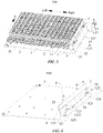
- the PCB heat dissipation assembly 100 includes a PCB board 1, at least one heat sink 2, and an air baffle 3.
- a plurality of chips 11 are arranged on the PCB board 1, the heat sink 2 is arranged on the plurality of chips 11, and the heat sink 2 includes a heat dissipation air duct 21.
- the air baffle 3 is arranged adjacent to the at least one heat sink 2, the air baffle 3 is located on one side of the at least one heat sink 2, and the air baffle 3 extends along the heat dissipation air duct 21.
- the plurality of chips 11 are arranged on the PCB board 1, and a plurality of heat sinks 2 each including a heat dissipation air duct 21 are arranged on the plurality of chips 11, so that heat generated by the chips 11 can be directly and adequately conducted to the heat sinks 2.
- the air baffle 3 is located on the right side of the plurality of heat sinks 2, and an extension direction of the air baffle 3 is the same as an extension direction of the heat dissipation air duct 21.
- the air baffle 3 can stop air sent out by the fan, to prevent the air from flowing out along a gap between the heat sink 2 and a case wall of the server, such that the air can be sent out by the heat sinks 2 located above the chips 11, thereby dissipating the heat from the heat sinks 2 and discharging the heat out of the server.
- the air baffle 3 can improve an internal air duct of the server and reduce the loss of heat dissipation air, so that more air can flow through the heat sink 2 and take away the heat generated by the chips 11, thereby effectively improving the heat dissipation efficiency of the PCB heat dissipation assembly 100.
- the air baffle 3 thus arranged is structurally simple, occupies a small space, and has lower costs.
- the air baffle 3 is arranged on the side adjacent to the heat sink 2 and the air baffle 3 extends along the heat dissipation air duct 21 of the heat sink 2, and the air baffle 3 stops air such that the air can flow through the heat sink 2 and adequately dissipate the heat generated by the chips 11, thereby effectively improving the heat dissipation efficiency of the PCB heat dissipation assembly 100.
- the air baffle 3 thus arranged is structurally simple, occupies a small space, and has lower costs.
- one end of the air baffle 3 is provided with an air guide plate 4.
- a flow direction of heat dissipation airflow is shown by the arrow in FIG. 1 , FIG. 3 , and FIG. 5 .
- the air guide plate 4 thus arranged can play a good role in guiding air, such that the air can adequately flow through the heat sink 2 and discharge the heat from the heat sink 2 out of the server case, thereby further improving the heat dissipation efficiency of the PCB heat dissipation assembly 100.
- the air baffle 3 and the air guide plate 4 may be metal pieces or non-metal pieces.
- a distance between the air guide plate 4 and the heat sink 2 gradually increases in a direction away from the air baffle 3.
- the air baffle 3 and the air guide plate 4 are both in a welded connection to the PCB board 1.
- a firm connection between the air baffle 3 and the PCB board 1 and between the air guide plate 4 and the PCB board 1 can be implemented, and the production cost of the PCB heat dissipation assembly 100 can be reduced.
- the air baffle 3 and the air guide plate 4 can be welded to the PCB board 1 by means of a through-hole technology or an SMT (an acronym for surface mount technology, which is an assembly technology that allows surface mounted components to be attached and welded onto a specified position on the surface of a printed circuit board, without the need to drill a mounting hole in the printed circuit board), etc.
- SMT surface mount technology
- the bottom of the air baffle 3 is provided with a first bent edge 31
- the bottom of the air guide plate 4 is provided with a second bent edge 41
- the air baffle 3 is in a welded connection to the PCB board 1 by means of the first bent edge 31
- the air guide plate 4 is in a welded connection to the PCB board 1 by means of the second bent edge 41
- the first bent edge 31 and the second bent edge 41 are spaced apart.
- providing the first bent edge 31 and the second bent edge 41 allows the connection between the air baffle 3 and the PCB board 1 and between the air guide plate 4 and the PCB board 1 to be firmer; and spacing apart the first bent edge 31 and the second bent edge 41 can effectively avoid stress concentration, thereby further ensuring the firmness of welding between the first bent edge 31 and the PCB board 1 and between the second bent edge 41 and the PCB board 1.
- the air baffle 3 is in a threaded connection to the PCB board 1. In this way, a firm connection between the air baffle 3 and the PCB board 1 and between the air guide plate 4 and the PCB board 1 can also be implemented, and it allows for easy assembly/disassembly and replacement.
- At least one mounting bracket 12 and at least one mounting bar 121 are fastened onto the PCB board 1, the at least one mounting bracket 12 and the at least one mounting bar 121 are spaced apart in a lengthwise direction of the air baffle 3, the air baffle 3 is in a threaded connection to the mounting bracket 12, the at least one mounting bar 121 is opposite the bottom of the air baffle 3, and the at least one mounting bar 121 is arranged between and presses against the air baffle 3 and the PCB board 1.
- FIG. 3 and FIG. 4 there are two mounting brackets 12 and four mounting bars 121 fastened (e.g., by means of SMT welding) onto the PCB board 1.
- the two mounting brackets 12 and the four mounting bars 121 are both spaced apart in the lengthwise direction of the air baffle 3.
- the mounting bars 121 spaced apart can prevent warping and deformation due to an excessive length of the mounting bars 121, so that the mounting bars 121 can be more firmly connected to the PCB board 1.
- the air baffle 3 is in a threaded connection to the mounting bracket 12, and the four mounting bars 121 are all arranged in a gap between the air baffle 3 and the PCB board 1.
- the air baffle 3 that is uneven at the bottom can be fastened onto the PCB board 1 by means of the mounting bracket 12.
- the at least one mounting bar 121 is provided, and the at least one mounting bar 121 can be arranged between and press against the air baffle 3 and the PCB board 1, preventing the heat dissipation air from being lost from the gap between the air baffle 3 and the PCB board 1, thereby further improving the heat dissipation efficiency of the PCB heat dissipation assembly 100.
- FIG. 3 and FIG. 4 two mounting brackets 12 and four mounting bars 121 are shown for the purpose of exemplary illustration. However, upon reading the technical solution of the present application, those of ordinary skill can obviously understand that applications of the solution in technical solutions in which there are other numbers of mounting brackets 12 and mounting bars 121 also fall within the scope of protection of the present disclosure.
- a thickness of the bottom of the mounting bracket 12 may be less than a thickness of the mounting bar 121.
- a thickness of the bottom of the mounting bracket 12 may be less than a thickness of the mounting bar 121.
- two mounting brackets 12 and five mounting bars 121 are shown.
- the bottom of the mounting bracket 12 is substantially L-shaped, and a thickness of the bottom of each of the two mounting brackets 12 is less than a thickness of each of the mounting bars 121.
- a part of the air baffle 3 that is opposite the mounting bracket 12 protrudes from a part thereof opposite the mounting bar 121, such that the bottom of the air baffle 3 can be in contact with the mounting bracket 12 and the mounting bar 121, to prevent the heat dissipation air from being lost from a gap between the air baffle 3 and the mounting bracket 12 or between the air baffle 3 and the mounting bar 121.
- the thickness of the bottom of each of the mounting brackets 12 may also be greater than or equal to the thickness of each of the mounting bars 121, provided that the bottom of the air baffle 3 can be in full contact with the mounting bar 121 and the mounting bracket 12.
- the mounting bracket 12 is provided with a connecting plate 122 extending upward, a first nut 1221 is arranged on a side of the connecting plate 122 that is away from the air baffle 3, and a first screw 5 passes through the air baffle 3 for a threaded connection to the first nut 1221, to fasten the air baffle 3 onto the mounting bracket 12.
- the mounting bracket 12 is provided with the connecting plate 122, and the connecting plate 122 extends upward vertically.
- the first nut 1221 is arranged on the left side of the connecting plate 122, and a central axis of the first nut 1221 extends horizontally.
- the first screw 5 passes through the air baffle 3 from right to left for a threaded connection to the first nut 1221, thereby fastening the air baffle 3 onto the mounting bracket 12.
- the first screw 5 needs to be removed from the first nut 1221. Therefore, providing the first nut 1221 ensures the structural strength of the connecting plate 122, and makes the entire PCB heat dissipation assembly 100 structurally simple, which facilitates the assembly/disassembly of the air baffle 3.
- the air baffle 3 is formed with a positioning hole 32, and the connecting plate 122 is provided with a positioning portion 1222 fitted in the positioning hole 32.
- the mounting bracket 12 is provided with the connecting plate 122 extending upward, and the positioning portion 1222 is connected at the top of the connecting plate 122 and extends toward the air baffle 3.
- the positioning portion 1222 reaches into the positioning hole 32 of the air baffle 3, and then the first screw 5 passes through the air baffle 3 and the connecting plate 122 for a threaded connection to the first nut 1221, thereby fastening the air baffle 3 onto the mounting bracket 12.
- providing the positioning portion 1222 can allow for the air baffle 3 to be more stably fastened onto the mounting bracket 12, which helps improve the heat dissipation efficiency of the PCB heat dissipation assembly 100, and can improve the structural stability of the entire PCB heat dissipation assembly 100.
- a spacer plate 33 is arranged on a side of the air baffle 3 that is away from the connecting plate 122, and the first screw 5 passes through the spacer plate 33 and the air baffle 3 for a threaded connection to the first nut 1221. Therefore, arranging the spacer plate 33 can increase an area of contact between the first screw 5 and the air baffle 3 and prevent the air baffle 3 from shaking, so that the air baffle 3 can be more firmly fastened onto the mounting bracket 12.
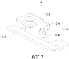
- the mounting bracket 12 is provided with a horizontally extending support plate 123; and the air baffle 3 is provided with at least one mating plate 34, the mating plate 34 is arranged on an upper surface of the support plate 123, and a second screw 6 passes through the mating plate 34 for a threaded connection to the support plate 123, to fasten the air baffle 3 onto the mounting bracket 12.
- the mounting bracket 12 is provided with the support plate 123.
- the mating plate 34 on the air baffle 3 is vertically aligned with the support plate 123, and the second screw 6 passes through the mating plate 34 from up to down for a threaded connection to the support plate 123, thereby fastening the air baffle 3 onto the mounting bracket 12.
- the second screw 6 needs to be disengaged from the support plate 123. In this way, the structure is also simple and allows for easy assembly/disassembly.
- the mounting bracket 12 is provided with an extension plate 124 extending upward, the support plate 123 is connected at the top of the extension plate 124, a second nut 1231 is arranged on a lower surface of the support plate 123, and the second screw 6 passes through the mating plate 34 and the support plate 123 for a threaded connection to the second nut 1231.
- the mounting bracket 12 is provided with the extension plate 124, and the extension plate 124 extends upward vertically. Two support plates 123 are respectively connected at the top of two extension plates 124.
- the second screw 6 passes through the mating plate 34 and the support plate 123 from up to down for a threaded connection to the second nut 1231 at the lower surface of the support plate 123, to implement firm fastening of the air baffle 3.
- the second screw 6 is disengaged from the second nut 1231. Therefore, the arrangement of the second nut 1231 increases the thickness of the support plate 123, which ensures the structural strength of the support plate 123, and can implement firm fastening of the air baffle 3.
- the extension plate 124 includes an extension plate body 1241 and a limiting plate 1242; and the air baffle 3 is provided with a notch 35, the support plate 123 is fitted at the notch 35, and edges of the notch 35 are fitted between the extension plate body 1241 and the limiting plate 1242.
- the opening of the notch 35 faces the mounting bracket 12.
- the mating plate 34 is in contact with the support plate 123 under the avoidance of the notch 35, and the edges of the notch 35 are located between the extension plate body 1241 and the limiting plate 1242. Therefore, fitting the edges of the notch 35 between the extension plate body 1241 and the limiting plate 1242 limits a left-right movement of the air baffle 3, thereby further ensuring the stability of the fastening of the air baffle 3.
- a server (not shown in the figure) according to an embodiment in a second aspect of the present disclosure includes a PCB heat dissipation assembly 100 according to the embodiment in the first aspect of the present disclosure.
- a fan is arranged on a side of the PCB heat dissipation assembly 100 of the server.
- a flow direction of heat dissipation airflow is shown by the arrow A in FIG. 1 , FIG. 3 , and FIG. 5 .
- One part of the heat dissipation airflow flows through the heat dissipation air duct 21 of the heat sink 2 and then flows out of the server, to take away the heat conducted from the chips 11 to the heat sink 2.
- the other part of the heat dissipation airflow flows between the air baffle 3 and the heat sink 2, which can also implement heat dissipation from the chips 11.
- the air baffle 3 can play a good role in stopping the air sent out by the fan, thereby reducing the loss of heat dissipation air, improving the heat dissipation efficiency of the PCB heat dissipation assembly 100, and thus improving the overall performance of the server.
- the use of the foregoing PCB heat dissipation assembly 100 makes the heat dissipation efficiency of the server higher, and can thus improve the overall performance of the server.
- orientation or position relationships indicated by terms such as “centre”, “longitudinal”, “transverse”, “length”, “width”, “thickness”, “up”, “down”, “front”, “rear”, “left”, “right”, “vertical”, “horizontal”, “top”, “bottom”, “inside”, “outside”, “axial”, “radial”, and “circumferential” are based on orientation or position relationships shown in the accompanying drawings and are merely for ease of description of the present disclosure and simplification of the description, rather than indicating or implying that the apparatuses or elements referred to must have a specific orientation or be constructed and operated in a specific orientation, and therefore cannot be construed as limiting the present disclosure.
- a "first feature” and a “second feature” may include one or more features.
Landscapes
- Engineering & Computer Science (AREA)
- Microelectronics & Electronic Packaging (AREA)
- Physics & Mathematics (AREA)
- General Engineering & Computer Science (AREA)
- Thermal Sciences (AREA)
- Computer Hardware Design (AREA)
- Theoretical Computer Science (AREA)
- Human Computer Interaction (AREA)
- General Physics & Mathematics (AREA)
- Cooling Or The Like Of Electrical Apparatus (AREA)
Applications Claiming Priority (1)
| Application Number | Priority Date | Filing Date | Title |
|---|---|---|---|
| PCT/CN2019/114832 WO2021081927A1 (zh) | 2019-10-31 | 2019-10-31 | Pcb散热组件和具有其的服务器 |
Publications (2)
| Publication Number | Publication Date |
|---|---|
| EP4007467A1 true EP4007467A1 (de) | 2022-06-01 |
| EP4007467A4 EP4007467A4 (de) | 2022-08-17 |
Family
ID=75715731
Family Applications (1)
| Application Number | Title | Priority Date | Filing Date |
|---|---|---|---|
| EP19951028.0A Withdrawn EP4007467A4 (de) | 2019-10-31 | 2019-10-31 | Leiterplatten-wärmeableitungsanordnung und server damit |
Country Status (3)
| Country | Link |
|---|---|
| US (1) | US12133367B2 (de) |
| EP (1) | EP4007467A4 (de) |
| WO (1) | WO2021081927A1 (de) |
Families Citing this family (2)
| Publication number | Priority date | Publication date | Assignee | Title |
|---|---|---|---|---|
| US12267984B2 (en) * | 2021-11-30 | 2025-04-01 | Delta Electronics, Inc. | Heat dissipation assembly |
| CN222885012U (zh) * | 2024-06-25 | 2025-05-16 | 锐捷网络股份有限公司 | 一种电子设备 |
Family Cites Families (19)
| Publication number | Priority date | Publication date | Assignee | Title |
|---|---|---|---|---|
| US6483699B1 (en) * | 2000-07-20 | 2002-11-19 | Silicon Graphics, Inc. | Baffle system for air cooled computer assembly |
| US6813149B2 (en) * | 2001-06-29 | 2004-11-02 | Intel Corporation | High capacity air-cooling systems for electronic apparatus and associated methods |
| TWI260484B (en) * | 2003-08-12 | 2006-08-21 | Asustek Comp Inc | Heat sink for power device on computer motherboard |
| JP4527492B2 (ja) * | 2004-10-20 | 2010-08-18 | Necインフロンティア株式会社 | 電子機器 |
| US20070235168A1 (en) * | 2006-04-10 | 2007-10-11 | Super Micro Computer, Inc. | Air flow diversion device for dissipating heat from electronic components |
| CN2904598Y (zh) * | 2006-05-19 | 2007-05-23 | 闻克俭 | 功放器主板散热装置 |
| US20080041562A1 (en) * | 2006-08-18 | 2008-02-21 | Sun Microsystems, Inc. | Airflow bypass and cooling of processors in series |
| CN201156862Y (zh) * | 2008-01-28 | 2008-11-26 | 鸿富锦精密工业(深圳)有限公司 | 具有导风板的网络设备 |
| CN201750358U (zh) * | 2010-09-21 | 2011-02-16 | 深圳市华意隆实业发展有限公司 | 一种具有完全隔离冷却风道的逆变焊机电源 |
| CN102548336A (zh) * | 2010-12-11 | 2012-07-04 | 鸿富锦精密工业(深圳)有限公司 | 导风罩 |
| CN102573398A (zh) * | 2010-12-28 | 2012-07-11 | 鸿富锦精密工业(深圳)有限公司 | 散热装置及其导风罩 |
| CN103165548A (zh) * | 2011-12-14 | 2013-06-19 | 鸿富锦精密工业(深圳)有限公司 | 散热器 |
| US10244661B2 (en) * | 2012-10-22 | 2019-03-26 | Iii Holdings 2, Llc | Airflow ducting apparatus for data processing systems |
| CN103901977A (zh) * | 2012-12-26 | 2014-07-02 | 鸿富锦精密工业(深圳)有限公司 | 散热装置 |
| US10602639B2 (en) * | 2016-04-15 | 2020-03-24 | Hewlett Packard Enterprise Development Lp | Extension portion of heatsink above a processing component |
| TWI682269B (zh) * | 2018-02-09 | 2020-01-11 | 緯創資通股份有限公司 | 電子計算裝置及其導流罩 |
| CN108762442B (zh) * | 2018-05-24 | 2020-04-28 | 华为技术有限公司 | 散热装置及其制造方法、服务器 |
| CN208848155U (zh) * | 2018-10-10 | 2019-05-10 | 贵州浪潮英信科技有限公司 | 一种高密度存储机型的散热架构 |
| TWI793757B (zh) * | 2021-09-09 | 2023-02-21 | 緯創資通股份有限公司 | 浸沒式冷卻系統及冷卻裝置 |
-
2019
- 2019-10-31 WO PCT/CN2019/114832 patent/WO2021081927A1/zh not_active Ceased
- 2019-10-31 US US17/636,644 patent/US12133367B2/en active Active
- 2019-10-31 EP EP19951028.0A patent/EP4007467A4/de not_active Withdrawn
Also Published As
| Publication number | Publication date |
|---|---|
| EP4007467A4 (de) | 2022-08-17 |
| WO2021081927A1 (zh) | 2021-05-06 |
| US12133367B2 (en) | 2024-10-29 |
| US20220272872A1 (en) | 2022-08-25 |
Similar Documents
| Publication | Publication Date | Title |
|---|---|---|
| CN219305276U (zh) | 工作组件和电子设备 | |
| US7447028B2 (en) | Heat dissipation device | |
| US7967059B2 (en) | Heat dissipation device | |
| CN100583363C (zh) | 等离子体显示模块机架结构和包括它的等离子体显示模块 | |
| EP2941109A1 (de) | Wärmeableitungsvorrichtung | |
| US20080115914A1 (en) | Heat dissipation device with heat pipes | |
| CN210274897U (zh) | 拼接式多层线路板 | |
| US12133367B2 (en) | PCB heat dissipation assembly and server having same | |
| JPWO2020174934A1 (ja) | 電子制御装置 | |
| WO2024083232A1 (zh) | 电子设备 | |
| CN210986568U (zh) | Pcb散热组件和具有其的服务器 | |
| US7365975B2 (en) | Heat dissipation device having a fan holder for attachment of a fan | |
| CN102938995A (zh) | 散热装置 | |
| US7256997B2 (en) | Heat dissipating device having a fan duct | |
| CN101578025B (zh) | 散热装置 | |
| JPWO2014097367A1 (ja) | ヒートシャッタ装置 | |
| CN113646884B (zh) | 散热器及电子部件封装体 | |
| CN215991668U (zh) | 基于fpga的图像处理pcb板 | |
| CN104994703A (zh) | 一种防尘散热器及其电源 | |
| EP3302015B1 (de) | Gehäuse und elektronische vorrichtung damit | |
| CN217506353U (zh) | 一种投影仪的新型散热结构 | |
| WO2020204077A1 (ja) | ヒートシンク及び電子部品パッケージ | |
| JP6610280B2 (ja) | 電子機器 | |
| CN213638615U (zh) | 电路板组合安装架 | |
| CN219172023U (zh) | 数码印刷机板卡模块及板卡组件 |
Legal Events
| Date | Code | Title | Description |
|---|---|---|---|
| STAA | Information on the status of an ep patent application or granted ep patent |
Free format text: STATUS: THE INTERNATIONAL PUBLICATION HAS BEEN MADE |
|
| PUAI | Public reference made under article 153(3) epc to a published international application that has entered the european phase |
Free format text: ORIGINAL CODE: 0009012 |
|
| STAA | Information on the status of an ep patent application or granted ep patent |
Free format text: STATUS: REQUEST FOR EXAMINATION WAS MADE |
|
| 17P | Request for examination filed |
Effective date: 20220126 |
|
| AK | Designated contracting states |
Kind code of ref document: A1 Designated state(s): AL AT BE BG CH CY CZ DE DK EE ES FI FR GB GR HR HU IE IS IT LI LT LU LV MC MK MT NL NO PL PT RO RS SE SI SK SM TR |
|
| A4 | Supplementary search report drawn up and despatched |
Effective date: 20220720 |
|
| RIC1 | Information provided on ipc code assigned before grant |
Ipc: G06F 1/20 20060101ALI20220714BHEP Ipc: H05K 7/20 20060101AFI20220714BHEP |
|
| DAV | Request for validation of the european patent (deleted) | ||
| DAX | Request for extension of the european patent (deleted) | ||
| GRAP | Despatch of communication of intention to grant a patent |
Free format text: ORIGINAL CODE: EPIDOSNIGR1 |
|
| STAA | Information on the status of an ep patent application or granted ep patent |
Free format text: STATUS: GRANT OF PATENT IS INTENDED |
|
| INTG | Intention to grant announced |
Effective date: 20240503 |
|
| STAA | Information on the status of an ep patent application or granted ep patent |
Free format text: STATUS: THE APPLICATION IS DEEMED TO BE WITHDRAWN |
|
| 18D | Application deemed to be withdrawn |
Effective date: 20240904 |