EP4007468B1 - Terminal mobile, chambre à vapeur et son procédé de préparation, et dispositif électronique - Google Patents
Terminal mobile, chambre à vapeur et son procédé de préparation, et dispositif électronique Download PDFInfo
- Publication number
- EP4007468B1 EP4007468B1 EP21741648.6A EP21741648A EP4007468B1 EP 4007468 B1 EP4007468 B1 EP 4007468B1 EP 21741648 A EP21741648 A EP 21741648A EP 4007468 B1 EP4007468 B1 EP 4007468B1
- Authority
- EP
- European Patent Office
- Prior art keywords
- vapor chamber
- cover plate
- material layer
- middle frame
- copper
- Prior art date
- Legal status (The legal status is an assumption and is not a legal conclusion. Google has not performed a legal analysis and makes no representation as to the accuracy of the status listed.)
- Active
Links
Images









Classifications
-
- H—ELECTRICITY
- H05—ELECTRIC TECHNIQUES NOT OTHERWISE PROVIDED FOR
- H05K—PRINTED CIRCUITS; CASINGS OR CONSTRUCTIONAL DETAILS OF ELECTRIC APPARATUS; MANUFACTURE OF ASSEMBLAGES OF ELECTRICAL COMPONENTS
- H05K7/00—Constructional details common to different types of electric apparatus
- H05K7/20—Modifications to facilitate cooling, ventilating, or heating
- H05K7/2029—Modifications to facilitate cooling, ventilating, or heating using a liquid coolant with phase change in electronic enclosures
- H05K7/20336—Heat pipes, e.g. wicks or capillary pumps
-
- H—ELECTRICITY
- H04—ELECTRIC COMMUNICATION TECHNIQUE
- H04M—TELEPHONIC COMMUNICATION
- H04M1/00—Substation equipment, e.g. for use by subscribers
- H04M1/02—Constructional features of telephone sets
- H04M1/18—Telephone sets specially adapted for use in ships, mines, or other places exposed to adverse environment
- H04M1/185—Improving the shock resistance of the housing, e.g. by increasing the rigidity
-
- H—ELECTRICITY
- H05—ELECTRIC TECHNIQUES NOT OTHERWISE PROVIDED FOR
- H05K—PRINTED CIRCUITS; CASINGS OR CONSTRUCTIONAL DETAILS OF ELECTRIC APPARATUS; MANUFACTURE OF ASSEMBLAGES OF ELECTRICAL COMPONENTS
- H05K7/00—Constructional details common to different types of electric apparatus
- H05K7/20—Modifications to facilitate cooling, ventilating, or heating
- H05K7/2039—Modifications to facilitate cooling, ventilating, or heating characterised by the heat transfer by conduction from the heat generating element to a dissipating body
- H05K7/20509—Multiple-component heat spreaders; Multi-component heat-conducting support plates; Multi-component non-closed heat-conducting structures
-
- G—PHYSICS
- G06—COMPUTING OR CALCULATING; COUNTING
- G06F—ELECTRIC DIGITAL DATA PROCESSING
- G06F1/00—Details not covered by groups G06F3/00 - G06F13/00 and G06F21/00
- G06F1/16—Constructional details or arrangements
- G06F1/20—Cooling means
-
- H—ELECTRICITY
- H04—ELECTRIC COMMUNICATION TECHNIQUE
- H04M—TELEPHONIC COMMUNICATION
- H04M1/00—Substation equipment, e.g. for use by subscribers
- H04M1/02—Constructional features of telephone sets
- H04M1/0202—Portable telephone sets, e.g. cordless phones, mobile phones or bar type handsets
-
- H—ELECTRICITY
- H05—ELECTRIC TECHNIQUES NOT OTHERWISE PROVIDED FOR
- H05K—PRINTED CIRCUITS; CASINGS OR CONSTRUCTIONAL DETAILS OF ELECTRIC APPARATUS; MANUFACTURE OF ASSEMBLAGES OF ELECTRICAL COMPONENTS
- H05K7/00—Constructional details common to different types of electric apparatus
- H05K7/20—Modifications to facilitate cooling, ventilating, or heating
- H05K7/2029—Modifications to facilitate cooling, ventilating, or heating using a liquid coolant with phase change in electronic enclosures
- H05K7/20327—Accessories for moving fluid, for connecting fluid conduits, for distributing fluid or for preventing leakage, e.g. pumps, tanks or manifolds
-
- G—PHYSICS
- G06—COMPUTING OR CALCULATING; COUNTING
- G06F—ELECTRIC DIGITAL DATA PROCESSING
- G06F2200/00—Indexing scheme relating to G06F1/04 - G06F1/32
- G06F2200/20—Indexing scheme relating to G06F1/20
- G06F2200/201—Cooling arrangements using cooling fluid
-
- H—ELECTRICITY
- H04—ELECTRIC COMMUNICATION TECHNIQUE
- H04M—TELEPHONIC COMMUNICATION
- H04M1/00—Substation equipment, e.g. for use by subscribers
- H04M1/02—Constructional features of telephone sets
- H04M1/0202—Portable telephone sets, e.g. cordless phones, mobile phones or bar type handsets
- H04M1/0206—Portable telephones comprising a plurality of mechanically joined movable body parts, e.g. hinged housings
-
- Y—GENERAL TAGGING OF NEW TECHNOLOGICAL DEVELOPMENTS; GENERAL TAGGING OF CROSS-SECTIONAL TECHNOLOGIES SPANNING OVER SEVERAL SECTIONS OF THE IPC; TECHNICAL SUBJECTS COVERED BY FORMER USPC CROSS-REFERENCE ART COLLECTIONS [XRACs] AND DIGESTS
- Y02—TECHNOLOGIES OR APPLICATIONS FOR MITIGATION OR ADAPTATION AGAINST CLIMATE CHANGE
- Y02E—REDUCTION OF GREENHOUSE GAS [GHG] EMISSIONS, RELATED TO ENERGY GENERATION, TRANSMISSION OR DISTRIBUTION
- Y02E60/00—Enabling technologies; Technologies with a potential or indirect contribution to GHG emissions mitigation
- Y02E60/10—Energy storage using batteries
Definitions
- This application relates to the field of mobile terminal technologies, and in particular, to a mobile terminal, a vapor chamber and a preparation method thereof, and an electronic device.
- a hole is formed in a part of a middle frame, and a vapor chamber is embedded in the middle frame.
- strength of an entire structure of the middle frame is decreased after the hole formation.
- Existing vapor chambers also tend to have a light weight, a small thickness, a large area, and a large span.
- a plate material with a small thickness or a large area and a large span decreases structural strength of the vapor chamber, the vapor chamber is always prone to deformation under the action of bending, twisting, pressing, or the like, and a cooling function thereof is affected. Therefore, how to improve stability of an entire structure of a mobile terminal without affecting cooling becomes a design focus.
- CN 110 234 212 A describes a heat sink with a capillary structure.
- this application provides a mobile terminal, a vapor chamber and a preparation method thereof, and an electronic device.
- the vapor chamber and the middle frame are combined for use as a structural supporting member, so as to improve structural strength of the vapor chamber and improve overall structural stability of the mobile terminal without affecting cooling.
- connection may be fixedly connect, detachably connect, integrally connect, or electrically connect; and may be directly connect, or indirectly connect by using a medium.
- a and/or B may represent the following three cases: Only A exists, both A and B exist, and only B exists, where A and B may be singular or plural.
- the symbol"/" generally represents an "or” relationship between associated objects.
- At least one of” or other similar expressions represent any combination of these items, including any combination of a singular or a plural.
- at least one of a, b, or c may represent a, b, c, a-b, a-c, b-c, or a-b-c, where a, b, and c may be singular or plural.
- a vapor chamber may generally be called a temperature equalization plate, a heat superconducting plate, or a heat conducting plate.
- a principle of a vapor chamber (Vapor chamber, VC for short) is similar to that of a heat pipe (Heat pipe).
- a liquid-phase medium (cooling medium) in a sealed cavity is boiled and transformed into a gas phase for heat absorption, the gas phase is condensed into a liquid phase for heat release, and capillary force, gravitational force, or the like are used as liquid-phase medium conveying power to complete phase transformation cycling of a gas phase and a liquid phase in a cold region and a hot region of the VC, so as to implement efficient heat exchange by using latent heat of phase transformation, heat conduction, convection, or the like.
- the vapor chamber may be considered as a heat pipe with a higher degree of shape freedom. While an irregular-design and large-span instantaneous pipe is applied to one-dimensional cooling, the vapor chamber may be further applied to two-dimensional cooling and three-dimensional cooling.
- the vapor chamber provided in the technical solutions of this application is applied to an electronic device such as a mobile phone, a tablet computer, a laptop, and an associated module, structural part and functional part with a cooling function.
- the electronic device includes a working module and a cooling module, where the cooling module includes a vapor chamber 100, and the vapor chamber 100 is configured to cool the working module.
- FIG. 1 is a schematic structural diagram of a vapor chamber in the prior art.
- the vapor chamber 100' includes an upper cover plate 10', a lower cover plate 20', a capillary structure 30', a medium (not shown in the figure), and the like.
- the upper cover plate 10' and the lower cover plate 20' of the vapor chamber may be sealed through welding to form a sealed cavity 40'
- the capillary structure layer 30' may be arranged in the sealed cavity 40'
- the capillary structure layer 30' is filled with a certain quantity of the cooling medium (for example, water), so as to form a phase transformation cycling system.
- a cooling process of the vapor chamber is a two-phase cooling process in which gas-liquid two-phase transformation is performed by using a cooling medium.
- the capillary structure is generally a copper-based porous medium, for example, copper mesh, sintered copper powder, and foamy copper, and may be generated by using a method such as copper mesh knitting, wire drawing, etching, electroplating, chemical depositing, or the like.
- the supporting structure may be prepared separately and then fixed to a plate material of the upper and lower cover plates through welding or the like, or may be directly machined on a plate material of the upper and lower cover plates.
- a main material is copper. Copper has good thermal conductivity, and also the copper capillary structure is relatively easy to prepare and does not have chemical reaction with water.
- the sealed cavity is in a negative pressure state inside, and the sealed cavity is mainly configured to prevent loss of the cooling medium and keep the vacuum negative pressure state, and has a particular deformation-resistant effect.
- the capillary structure is configured to form capillary force to convey the cooling medium. Completing whole power cycling to complete thermodynamic cycling is a key to keep two phases exchanging heat.
- FIG. 2 is a diagram contrasting equivalent heat conduction coefficients of a vapor chamber, pure copper, and a heat pipe.
- liquid water absorbs heat in a heat source to be evaporated into vapor and absorbs a large amount of latent heat.
- the vapor moves in the sealed cavity to a cold end to release heat and is condensed into liquid water. Then the liquid water flows back to an evaporation section by using the capillary structure.
- the equivalent heat conduction coefficient of the vapor chamber is more than 20 times that of the pure copper.
- a material of the upper and lower cover plates of the existing vapor chamber is copper or copper alloy, which is prone to deformation. Under external acting force such as bending, twisting and stretching and internal pressure such as curing and swelling of an internal medium, the vapor chamber is prone to deformation, causing adverse effects to the electronic device that uses the vapor chamber.
- one of stainless steel, titanium, titanium alloy, tungsten, tungsten alloy, chromium, or chromium alloy may be used to prepare the upper and lower cover plates and/or the supporting structure.
- the supporting structure is disposed between the upper and lower cover plates, so as to improve deformation-resistant capability of the entire vapor chamber.
- Table 1 shows contrastive physical parameters of several common high-strength metal materials.
- Table 2 shows a comparison of performance parameters of vapor chambers made of stainless steel or copper alloy. Table 1.
- yield strength, elasticity modulus, and surface hardness of stainless steel and titanium are all greater than those of copper or copper alloy.
- Table 2 Comparison of performance parameters of vapor chambers made of stainless steel or copper alloy Surface material Copper alloy Stainless steel Test force (gf) 100 100 Duration (s) 10 10 Surface hardness (Hv) Test 1 82.91 158.96 Test 2 83.22 156.54 Test 3 78.49 161.43 Average 81.5 159
- a surface hardness (159 Hv) of stainless steel is greater than a surface hardness (81.5 Hv) of copper alloy, which is an increase of 95% than the latter.
- FIG. 3 is a schematic diagram of a working principle of a vapor chamber provided in an embodiment of this application.
- the vapor chamber 100 includes an evaporation region and a cooling region, where the two regions are determined based on specific requirements of working scenarios, may be an entire upper cover plate or an entire lower cover plate respectively, or may be a part of the upper cover plate or the lower cover plate.
- a cooling medium in a sealed cavity is heated in a low-vacuum environment and starts to be evaporated, and also absorbs heat energy for rapid volume expansion, the entire sealed cavity is rapidly filled with the gas-phase cooling medium, and the gas-phase cooling medium enters the cooling region to be condensed.
- the heat accumulated in evaporation is released, and the condensed cooling medium returns to the evaporation heat source by using the capillary structure. This operation is cyclically performed in the sealed cavity.
- a cooling function of the vapor chamber is mainly implemented through gas-liquid two-phase transformation of the cooling medium.
- a cooling process of the vapor chamber includes four major steps: conduction, evaporation, convection, and condensation. Evaporation inside the vapor chamber is continuously performed, and as temperature changes, internal pressure of the vapor chamber keeps balance correspondingly.
- the vapor chamber is large in size range and flexible in layout, and size of the vapor chamber may be designed based on actual size and distribution of the heat source, so that the heat source is flexibly covered, and a plurality of heat sources are simultaneously cooled.
- the vapor chamber 100 in the embodiments provides a sealed space, in which gas-liquid two-phase transformation of the cooling medium is performed.
- gas-liquid two-phase transformation of the cooling medium is performed.
- water is generally selected as the cooling medium.
- the compatibility problem means the problem that a plate material of a housing and a working medium react to generate non-condensable gas, causing failure of the vapor chamber of a two-phase cooling system.
- the non-condensable gas such as H 2 or O 2
- continuously breaks a negative pressure environment in the vapor chamber causing the vapor chamber unable to normally work and failure.
- Copper has good thermal conductivity, and also the copper capillary structure is relatively easy to prepare and does not have chemical reaction with water, so that a negative pressure environment is not broken. Therefore, for the copper-based or copper-alloy-based vapor chamber, durability of the vapor chamber can be improved.
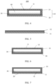
- FIG. 4 is an overall schematic structural diagram of a high-strength vapor chamber according to an embodiment of this application.
- the vapor chamber 100 includes a housing 110 and a capillary structure 30.
- the housing 110 includes a first cover plate 10 and a second cover plate 20, where the first cover plate 10 and the second cover plate 20 are connected in a sealed manner to form a sealed cavity 40.
- An interior of the sealed cavity 40 is a negative pressure environment, and a cooling medium is provided. Further, with an opening provided in the housing 110, the sealed cavity 40 may be vacuumized in advance, and the cooling medium such as deionized water, methanol, or acetone is injected.
- a material of the first cover plate 10 and/or the second cover plate 20 is a high-strength composite material
- the high-strength composite material includes at least one first material layer 11 and at least one second material layer 12
- a material of the first material layer 11 is at least one of stainless steel, titanium, titanium alloy, tungsten, tungsten alloy, chromium, and chromium alloy
- a material of the second material layer 12 is copper or copper alloy.
- the second material layer 12 is located on an inner side of the housing 110, and the first material layer 11 is not in contact with the cooling medium.
- the first material layer and the second material layer may be laminated through vacuum hot rolling, vacuum cold rolling, vacuum diffusion welding, or the like to form the high-strength composite material, or at least one surface of the first material layer may be covered with the second material layer through treatment such as electroplating and chemical depositing on the first material layer.
- the high-strength composite material may include a first material layer 11 and a second material layer 12, where the first material layer 11 may be formed by laminating a stainless steel layer, a titanium layer, and a titanium alloy layer.
- the first material layer 11 is prepared from a plurality of metal layers of different densities by using a lamination process such as electroplating, rolling and bonding.
- the high-strength composite material may alternatively be prepared by using a lamination process such as electroplating, rolling and bonding.
- first cover plate 10 and the second cover plate 20 may be different in thickness.
- a thickness of the cover plate facing towards a battery surface may be greater than a thickness of the cover plate facing towards a display surface.
- the cover plate made of the high-strength composite material may be used as a reinforcing structure for a middle frame, this can avoid that the middle frame with a large area hollowed out is provided with strength only by a middle frame side wall, causing a great decline of strength, and especially for a curved screen and a widened antenna gap, the middle frame side wall is thinned, meaning that with optimization and reinforcement of the vapor chamber 100, rigidity of the middle frame can meet use requirements.
- a surface hardness of the cover plate made of the high-strength composite material is greater than or equal to 120 Hv, and specifically may be 120 Hv, 150 Hv, 170 Hv, 180 Hv, 200 Hv, 220 Hv, 250 Hv, or the like. This is not limited herein.
- the capillary structure 30 is disposed in the sealed cavity 40. Specifically, the capillary structure 30 may be parallel to the first cover plate 10 and the second cover plate 20, or may be arranged based on design requirements. This is not limited herein.
- the capillary structure 30 is filled with the cooling medium, where the cooling medium may be, for example, deionized water, methanol, or acetone. Cooling of the vapor chamber may be implemented through gas-liquid two-phase transformation of the working medium. A specific cooling principle and cooling path of the capillary structure are described as above.
- the capillary structure 30 may be connected to an inner surface of the housing 110, or may not be connected to an inner surface of the housing 110.
- the capillary structure 30 is a porous metallic medium.
- a material of the capillary structure is copper or copper alloy, and the capillary structure may be, for example, one or more of copper mesh, copper fiber, copper powder, or foamy copper.
- the capillary structure 30 may be disposed on the second material layer 12 of the first cover plate 10 and/or the second cover plate 20.
- the copper mesh may be combined with a surface of the first cover plate 10 facing towards the second cover plate 20 through sintering, soldering, cold pressing, or the like.
- the copper mesh is fixed to the inner surface of the housing 110, to be specific, the second material layer 12 of the first cover plate 10 or the second material layer 12 of the second cover plate 20 through sintering, soldering, cold pressing, or the like, so that the copper mesh is prevented from displacement in use, and working stability of a product is ensured.
- the copper mesh may alternatively be placed in the sealed cavity 40 without any connection processing, so as to prevent the housing 110 from being affected by sintering, soldering, cold pressing, or the like, and ensure structural stability of the housing 110.
- the sealed cavity 40 of the vapor chamber is provided with an opening that communicates with the outside.
- the opening may be a liquid injection opening or a vacuumizing opening. Injecting the cooling medium into the sealed cavity 40 through the opening, performing vacuumizing treatment on the sealed cavity 40 through the opening and then sealing the opening allow for a vacuum negative pressure state of the sealed cavity 40.
- the sealed cavity 40 is vacuumized, the injected cooling medium is under negative pressure, and the cooling medium is evaporated once being heated in the evaporation region.
- the evaporated cooling medium swells to fill the entire cavity, in the cooling region, the gas cooling medium releases heat and is liquefied into a liquid cooling medium, and the liquefied cooling medium returns to the evaporation region by using the capillary structure 30. In this way, a heat transfer cycle is formed in the sealed cavity 40.
- the vapor chamber provided in this embodiment, strength of the vapor chamber can be improved, and also the high-strength material (such as stainless steel) can be separated from a medium such as water, so as to greatly mitigate or eliminate a compatibility problem.
- the high-strength material such as stainless steel
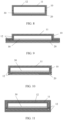
- FIG. 6 to FIG. 9 each are a schematic structural diagram of a vapor chamber according to an embodiment of this application.
- the first cover plate 10 or the second cover plate 20 made of the high-strength composite material can increase strength and deformation-resistant capability of the vapor chamber.
- Shape, edge sealing form, connection manner, and the like of the first cover plate 10 and the second cover plate 20 may all be correspondingly designed and changed based on actual needs.
- the first cover plate 10 and/or the second cover plate 20 made of the high-strength composite material can improve strength and deformation-resistant capability of the vapor chamber.
- the second material layer 12 made of the high-strength composite material is disposed on the inner side of the housing 110, so that the first material layer 11 can be separated from a medium such as water, thereby greatly mitigating or eliminating a compatibility problem and preventing non-condensable gas that breaks a negative pressure environment from being generated by reaction of water and stainless steel.
- the second cover plate 20 may only include a second material layer, excluding a first material layer.
- the first cover plate 10 may only include a second material layer, excluding a first material layer.
- FIG. 10 is a schematic structural diagram of another vapor chamber according to an embodiment of this application.
- the high-strength composite material is not limited to the first material layer 11 and the second material layer 12 that are stacked, the first material layer 11 and the second material layer 12 may be spliced, and the splicing manner may be partial splicing or full splicing.
- the first material layer 11 and the second material layer 12 may be the same or different in area, and each first material layer 11 and each second material layer 12 may be the same or different in thickness.
- FIG. 11 is a schematic structural diagram of another vapor chamber according to an embodiment of this application.
- the high-strength composite material further includes a third material layer, where the first material layer is sandwiched between the second material layer and the third material layer, and a material of the third material layer is copper or copper alloy.
- the second material layer 12 and the third material layer 13 may be the same or different in thickness.
- a thickness of the first cover plate and a thickness of the second cover plate each are less than or equal to 0.15 mm. Shape, edge sealing form, connection manner, and the like of the first cover plate and the second cover plate may all be correspondingly designed and changed based on actual needs.
- the cooling medium is deionized water. It may be understood that, water that serves as the most commonly used cooling medium and that is low in production cost and easy to prepare facilitates reducing production costs of the entire vapor chamber, and compared with methanol, acetone, and the like, water as the cooling medium is safer and more reliable.
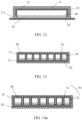
- FIG. 12 is a schematic structural diagram of another vapor chamber according to an embodiment of this application. As shown in FIG. 12 , in an actual preparation process, the first cover plate 10 and the second cover plate 20 may be connected in a sealed manner through welding, bonding, or the like to form the sealed cavity 40. Specifically, the second material layer 12 of the first cover plate 10 and the second material layer 12 of the second cover plate 20 enclose the sealed cavity 40, so as to prevent the cooling medium from contact with the first material layer 11.
- the housing 110 of the vapor chamber 100 further includes a fusion layer 111, where the fusion layer 111 is configured to connect the first cover plate 10 and the second cover plate 20, so as to connect the first cover plate 10 and the second cover plate 20 in a sealed manner to form the sealed cavity 40, meaning that the fusion layer 111 may be a welding layer or a bonding layer formed through a treatment process such as welding or bonding.
- FIG. 13 is a schematic structural diagram of another vapor chamber according to an embodiment of this application.
- the vapor chamber 100 further includes a supporting structure 50, where the supporting structure 50 may be configured to keep the shape of the housing 110 and improve strength of the vapor chamber.
- the supporting structure 50 extends from an inner surface of the housing 110 to an internal space of the housing 110.
- a channel between the supporting structure 50 is a vapor channel and/or a capillary structure. It may be understood that the supporting structure can be configured to prevent the vapor chamber from deformation caused by atmospheric pressure difference between inside and outside and other external force, so as to prevent the vapor channel and the capillary structure from being crushed and causing the vapor chamber to fail.
- the supporting structure 50 is disposed on the second cover plate 20.
- the supporting structure 50 is arranged on the second cover plate 20 in an array.
- the supporting structure 50 has a supporting protection effect in the sealed cavity 40, so as to prevent the sealed cavity 40 of the vapor chamber 100 from squeezing deformation.
- the supporting structure 50 abuts against the first cover plate 10 and/or the second cover plate 20.
- a height of the supporting structure 50 is equal to a height of the sealed cavity 40.
- the supporting structure 50 arranged in an array facilitates light weight design of the vapor chamber, facilitates uniform distribution of mass of the vapor chamber, and facilitates design control over a gravity center of the entire electronic device.
- the supporting structure 50 may be directly machined and prepared on the first cover plate or the second cover plate. That is, the supporting structure 50 and the housing 110 are an integrated structure, and the supporting structure 50 is a plurality of protruding columns or protruding points arranged in an array. Specifically, for the first cover plate 10 and the second cover plate 20 prepared through etching, the second material layer 12 of the first cover plate 10 is over-etched for surface reduction to form a recessed surface, and the second material layer 12 of the second cover plate 20 is etched for surface reduction to form the protruding columns arranged in an array, where the protruding columns are the supporting structure 50.
- the supporting structure 50 machined through an etching process for reduction can greatly ensure connection stability of the supporting structure 50 and the second cover plate 20, so as to prevent a bonding or welding process in between and simplify a machining process. It may be understood that, in this embodiment, a material of the supporting structure 50 is copper or copper alloy, and with the high-strength housing in cooperation, strength of the entire vapor chamber can also be ensured.
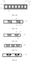
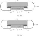
- FIG. 14a and FIG. 14b each are a schematic structural diagram of another vapor chamber according to an embodiment of this application.
- a material of the supporting structure 50 is a high-strength composite material
- a material of an inner core 51 of the supporting structure 50 is the material of the first material layer
- a material of a periphery 52 of the supporting structure 50 is the material of the second material layer.
- the supporting structure 50 may alternatively be prepared separately and then fixedly connected to the first cover plate or the second cover plate through welding or the like. Specifically, for the second cover plate 20 machined through stamping, a plate material of the second cover plate 20 is stamped for molding first and then reversely stretched to form a recessed region, and finally the supporting structure 50 and the second cover plate 20 are fixed through welding to form the supporting structure 50 uniformly arranged in an array, where the material of the periphery of the supporting structure and the material of the second material layer of the second cover plate each are copper or copper alloy.
- the inner core of the supporting structure is made of at least one material of stainless steel, titanium, titanium alloy, tungsten, tungsten alloy, chromium, or chromium alloy.
- the periphery of the supporting structure is made of copper or copper alloy. The periphery of the supporting structure can effectively separate the cooling medium from the first material layer, so as to eliminate a compatibility problem and prevent non-condensable gas from being generated.
- the high-strength supporting structure 50 improves strength of the entire vapor chamber, so as to prevent the sealed cavity of the vapor chamber 100 from squeezing deformation.
- the vapor chamber is a serial-structure vapor chamber; and when the vapor channel and the capillary structure are in parallel, as shown in FIG. 14b, FIG. 15a to FIG. 15c, FIG. 16 , FIG. 17, FIG. 19a, and FIG. 20a , the vapor chamber is a parallel-structure vapor chamber.
- the capillary structure 30 is flat laid on the second cover plate 20, and the capillary structure 30 is located at a bottom of each vapor channel.
- a material of the capillary structure 30 is copper or copper alloy.
- the capillary structure 30 is disposed on a periphery or two sides of the supporting structure 50 in an encircling manner and functions like the second material layer.
- the capillary structure separates the supporting structure from the cooling medium, so as to eliminate or greatly relieve a compatibility problem.
- the capillary structure 30 is disposed parallel to the vapor channel.
- the capillary structure 30 may alternatively be disposed on any side wall in the housing 110. This is not limited herein.
- FIG. 15a is a schematic structural diagram of another vapor chamber according to an embodiment of this application.
- a material of the supporting structure 50 is any one of stainless steel, titanium, titanium alloy, tungsten, tungsten alloy, chromium, or chromium alloy.
- the second material layer 12 and the capillary structure 30 are spliced and then disposed on a periphery of the supporting structure 50 in an encircling manner.
- a material of the second material layer and a material of the capillary structure each are copper or copper alloy.
- the second material layer 12 and the capillary structure 30 are spliced into a whole and then disposed on the periphery of the supporting structure 50 in the encircling manner, so as to separate the high-strength composite material from the cooling medium.
- the splicing manner may be partial splicing or half splicing. This is not limited herein.
- other metal material and the capillary structure 30 may alternatively be spliced and then disposed on the periphery of the supporting structure 50 in an encircling manner, and the splicing manner is not limited herein.
- other metal material may be, for example, any one of stainless steel, titanium, titanium alloy, tungsten, tungsten alloy, chromium, or chromium alloy.
- the inner core of the supporting structure is made of stainless steel, the periphery made of titanium alloy and the capillary structure made of copper are spliced, or the periphery made of titanium and the capillary structure made of copper alloy are spliced.
- the splicing manner is not limited.
- the supporting structure 50 may also be applied to the vapor chamber as illustrated in FIG. 4 to FIG. 12 , and the supporting structure may be made of copper or copper alloy, or made of the high-strength composite material.
- FIG. 17 is a schematic structural diagram of another vapor chamber according to an embodiment of this application.
- the capillary structure 30 is disposed on the periphery of the supporting structure 50 in an encircling manner, where a material of the supporting structure 50 is any one of stainless steel, titanium, titanium alloy, tungsten, tungsten alloy, chromium, or chromium alloy, and a material of the capillary structure 30 is copper or copper alloy.
- the capillary structure 30 is disposed on the periphery of the supporting structure 50 in the encircling manner, and the vapor channel is disposed parallel to the capillary structure 30, so that the supporting structure 50 is separated from the cooling medium, thereby eliminating or greatly relieving a compatibility problem and preventing non-condensable gas that breaks a negative pressure environment from being generated by reaction of the cooling medium and the first material layer of the housing 110.
- the capillary structure 30 fully covers the periphery of the supporting structure 50.
- the high-strength ultra-thin supporting structure 50 may be irregular in shape and different in cross section, for example, I-beam. As shown in FIG. 18 , the supporting structure 50 is irregular cylinder-shaped.
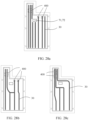
- FIG. 19a and FIG. 19b each are a top view of another vapor chamber according to an embodiment of this application
- FIG. 20a and FIG. 20b each are a top view of another vapor chamber according to an embodiment of this application.
- the supporting structure 50 is disposed in the sealed cavity 40.
- a plurality of supporting structures 50 may be disposed continuously or discontinuously.
- the supporting structure 50 is not limited in shape, for example, may be cylinder-shaped, cube-shaped, or cone-shaped.
- a plurality of supporting structures 50 may alternatively vary in shape. This is not limited herein.
- the capillary structure 30 encircles the supporting structure 50, and a material of the capillary structure 30 is copper or copper alloy, resembling the second material layer 12, so as to separate the supporting structure 50 made of the high-strength material from the cooling medium, greatly relieve a compatibility problem and prevent non-condensable gas from being generated.
- a common material such as copper may be selected; and as shown in FIG. 20a , the housing 110 may alternatively select a high-strength composite material.
- the supporting structure 50 in FIG. 19b and FIG. 20b is made of a high-strength composite material, and the supporting structure 50 includes an inner core 51 and a periphery 52 encircling the inner core 51, where a material of the inner core 51 is the material of the first material layer 11, for example, stainless steel, titanium, titanium alloy, tungsten, tungsten alloy, chromium, or chromium alloy.
- a material of the periphery 52 is the material of the second material layer 12: copper or copper alloy.
- the capillary structure 30 is flat laid on the second material layer of the first cover plate 10 and/or the second cover plate 20, and a material of the capillary structure 30 is copper or copper alloy, so as to separate the supporting structure 50 made of the high-strength composite material from the cooling medium, greatly relieve a compatibility problem and prevent non-condensable gas from being generated.
- a thickness of the first cover plate 10 and a thickness of the second cover plate 20 each are less than or equal to 0.15 mm.
- FIG. 21a to FIG. 21c each are a schematic structural diagram of another vapor chamber according to an embodiment of this application.
- the vapor chamber 100 further includes a step fixing part 60 formed by extending along at least a part of an edge of the vapor chamber 100, where the step fixing part 60 is configured to mount and fix the vapor chamber 100.
- the step fixing part 60 may be an edge of the first cover plate 10, and a vertical projected area of the first cover plate 10 is greater than a vertical projected area of the second cover plate 20.
- the step fixing part 60 may alternatively be an edge of the second cover plate 20, and a vertical projected area of the second cover plate 20 is greater than a vertical projected area of the first cover plate 10.
- the step fixing part 60 may still alternatively be an integrated edge of the first cover plate 10 and the second cover plate 20 that is formed through connection.
- a vertical projected area of the second cover plate 20 is the same as a vertical projected area of the first cover plate 10.
- the step fixing part 60 may be directly welded or bonded to a to-be-mounted object, and the step fixing part 60 formed by extending the first cover plate 10 and/or the second cover plate 20 can improve mounting structural stability of the vapor chamber and can also reduce the thickness of the vapor chamber and prevent an additional fixing structure from being added.
- the to-be-mounted object may be, for example, a middle frame of the electronic device.
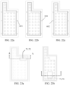
- FIG. 22a to FIG. 22c each are a schematic structural diagram of a step fixing part of a vapor chamber according to an embodiment of this application. As shown in FIG. 22a to FIG.
- holes 601 and/or slots 602 are provided in the step fixing part 60, so that fixing structures such as rivets, screws, or bolts pass through the holes 601 and/or the slots 602 to fix the vapor chamber 100 to the middle frame.
- the holes 601 and/or the slots 602 may be arranged at equal intervals along the step fixing part 60, or may be arranged at unequal intervals.
- the holes 601 and the slots 602 are not limited in shape, and may be circular, elliptical, square, fan-shaped, or the like.
- the vapor chamber 100 is provided with a mounting recess 71 and/or a mounting hole 72 in a thickness direction, where the mounting recess 71 and/or the mounting hole 72 are/is configured to mount the electronic component, and the electronic component may be, for example, a flexible printed circuit, a fingerprint module, or a screen module.
- the mounting recess 71 or the mounting hole 72 is provided in an edge of the vapor chamber 100, and the capillary structure 30 is disposed on a part of an edge of the mounting recess 71 or the mounting hole 72 in an encircling manner, that is, the mounting recess 71 or the mounting hole 72 adjoins the capillary structure 30 of the vapor chamber 100.
- the capillary structure 30 is disposed on a periphery of the mounting recess 71 or the mounting hole 72 in a full encircling manner.
- the mounting recess 71 or the mounting hole 72 may alternatively be provided in the step fixing part 60 of the vapor chamber 100.
- the capillary structure 30 may be absent from the periphery of the mounting recess 71 or the mounting hole 72. It may be understood that, compared with a recess region without the capillary structure 30, a region with the capillary structure 30 has a higher heat conduction coefficient and a better cooling effect.
- the mounting recess 71 is formed in the first cover plate 10 or the second cover plate 20 the vapor chamber 100 in a thickness direction, that is, a depth of the mounting recess 71 is less than a thickness of the first cover plate 10 or a thickness of the second cover plate 20.
- the mounting recess 71 may be square, circular, elliptical, or other irregular shaped, and may be formed through a process such as etching or partial stamping.
- the mounting hole 72 runs through the first cover plate 10 and/or the second cover plate 20. As shown in FIG. 24c , the mounting hole 72 runs through the second cover plate 20; and as shown in FIG.
- the mounting hole 72 runs through the first cover plate 10 and the second cover plate 20, that is, the mounting hole 72 runs through the entire vapor chamber 100.
- the mounting hole 72 that runs through the second cover plate 20 and the mounting recess 71 that is formed in the first cover plate 10 through recessing are located on two sides of the vapor chamber 100 respectively.
- the sealed cavity of the vapor chamber 100 is not affected by the mounting recess 71 and/or the mounting hole 72 provided in the vapor chamber 100, and the sealed cavity may keep a negative pressure state through partial welding (such as tin soldering) and bonding.
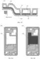
- the vapor chamber 100 includes a first section 101, a second section 102, and a bent section 103 connected to the first section 101 and the second section 102, where the first section 101 and the second section 102 have a height difference, and the capillary structure 30 keeps a continuous state in the first section 101, the second section 102, and the bent section 103.
- a part of the sealed cavity in the first section 101 and part of the sealed cavity in the second section 102 are different in height, that is, the entire vapor chamber 100 is a vapor chamber with different thicknesses, and an overall thickness of the first section 101 may be less than or greater than an overall thickness of the second section 102.
- the supporting structure 50 is disposed in the first section 101 and the second section 102, and a specific form of the supporting structure 50 is not limited herein.
- bent vapor chamber can be adapted to a small mounting space, so as to meet a partial cooling requirement of the electronic component; and moreover, increasing a height of a sealed chamber appropriately to enlarge the vapor channel in the vapor chamber facilitates two-phase heat exchange of the cooling medium and may improve cooling efficiency.
- the vapor chamber 100 may further include a third section and a second bent section connected to the third section and the second section, so that the vapor chamber 100 has a plurality of bent sections. It should be noted that because the vapor chamber provided in the embodiments of this application is made of the high-strength composite material, strength of the entire vapor chamber can still meet use requirements after bending treatment.
- An embodiment of this application further provides a preparation method of a vapor chamber.
- the method includes:
- the high-strength metal material such as stainless steel, titanium, titanium alloy, tungsten, tungsten alloy, chromium, or chromium alloy
- the first material layer 11 can be separated from a working medium such as water, so as to greatly mitigate or eliminate a compatibility problem.
- the capillary structure is generally a copper-based porous medium, for example, copper mesh, copper powder, and foamy copper, and may be generated by using a method such as copper mesh knitting, wire drawing, etching, electroplating, chemical depositing, or the like.
- the cooling medium may be, for example, water, deionized water, methanol, or acetone.
- the first cover plate or the second cover plate may alternatively form a supporting structure through etching, stamping, or the like, so as to further improve deformation-resistant capability of the vapor chamber.
- a high-strength composite material is selected to form a first cover plate and a second cover plate through stamping, and the high-strength composite material includes a first material layer made of stainless steel and a second material layer made of copper.
- a capillary structure is disposed between the first cover plate and the second cover plate, the first cover plate and the second cover plate are laser welded to form a housing with a sealed cavity, and the second material layer is located on an inner side of the housing.
- the capillary structure is made of copper powder.
- a thickness of the first cover plate and a thickness of the second cover plate each are 0.15 mm. Provided that test force of 300 gf is applied to the vapor chamber for 10 s, a surface hardness of the vapor chamber ranges from 180 HV to 400 HV
- a high-strength composite material is selected to form a first cover plate and a second cover plate through stamping, and the high-strength composite material includes a first material layer made of titanium and a second material layer made of copper.
- a capillary structure is disposed between the first cover plate and the second cover plate, the first cover plate and the second cover plate are laser welded to form a housing with a sealed cavity, and the second material layer is located on an inner side of the housing.
- the capillary structure is made of copper powder.
- a thickness of the first cover plate and a thickness of the second cover plate each are 0.15 mm. Provided that test force of 300 gf is applied to the vapor chamber for 10 s, a surface hardness of the vapor chamber ranges from 180 HV to 400 HV
- a high-strength composite material is selected to form a first cover plate and a second cover plate through stamping, and the high-strength composite material includes a first material layer made of titanium alloy and a second material layer made of copper.
- a capillary structure is disposed between the first cover plate and the second cover plate, the first cover plate and the second cover plate are laser welded to form a housing with a sealed cavity, and the second material layer is located on an inner side of the housing.
- the capillary structure is made of copper powder.
- a thickness of the first cover plate and a thickness of the second cover plate each are 0.15 mm. Provided that test force of 300 gf is applied to the vapor chamber for 10 s, a surface hardness of the vapor chamber ranges from 180 HV to 400 HV Comparative Example 1
- Comparative Example 1 copper is selected to form a first cover plate and a second cover plate through stamping, a capillary structure is disposed between the first cover plate and the second cover plate, the first cover plate and the second cover plate are laser welded to form a housing with a sealed cavity.
- the capillary structure is made of copper powder.
- a thickness of the first cover plate and a thickness of the second cover plate each are 0.15 mm. Provided that test force of 300 gf is applied to the vapor chamber for 10 s, a surface hardness of the vapor chamber ranges from 80 HV to 120 HV
- a high-strength composite material is selected to form a first cover plate and a second cover plate through stamping, and the high-strength composite material includes a first material layer made of stainless steel and a second material layer made of copper.
- a supporting structure uniformly arranged in an array is welded to the second cover plate, where a material of an inner core of the supporting structure is stainless steel, and a material of a periphery of the supporting structure is copper.
- a capillary structure is disposed between the first cover plate and the second cover plate, the first cover plate and the second cover plate are laser welded to form a housing with a sealed cavity, and the second material layer is located on an inner side of the housing.
- the capillary structure is made of copper powder.
- a thickness of the first cover plate and a thickness of the second cover plate each are 0.15 mm. Provided that test force of 300 gf is applied to the vapor chamber for 10 s, a surface hardness of the vapor chamber ranges from 180 HV to 400 HV
- a high-strength composite material is selected to form a first cover plate and a second cover plate through stamping, and the high-strength composite material includes a first material layer made of titanium and a second material layer made of copper.
- a supporting structure uniformly arranged in an array is welded to the second cover plate, where a material of an inner core of the supporting structure is titanium, and a material of a periphery of the supporting structure is copper.
- a capillary structure is disposed between the first cover plate and the second cover plate, the first cover plate and the second cover plate are laser welded to form a housing with a sealed cavity, and the second material layer is located on an inner side of the housing.
- the capillary structure is made of copper powder.
- a thickness of the first cover plate and a thickness of the second cover plate each are 0.15 mm. Provided that test force of 300 gf is applied to the vapor chamber for 10 s, a surface hardness of the vapor chamber ranges from 180 HV to 400 HV
- a high-strength composite material is selected to form a first cover plate and a second cover plate through stamping, and the high-strength composite material includes a first material layer made of titanium alloy and a second material layer made of copper.
- a supporting structure uniformly arranged in an array is welded to the second cover plate, where a material of an inner core of the supporting structure is titanium alloy, and a material of a periphery of the supporting structure is copper.
- a capillary structure is disposed between the first cover plate and the second cover plate, the first cover plate and the second cover plate are laser welded to form a housing with a sealed cavity, and the second material layer is located on an inner side of the housing.
- the capillary structure is made of copper powder.
- a thickness of the first cover plate and a thickness of the second cover plate each are 0.15 mm. Provided that test force of 300 gf is applied to the vapor chamber for 10 s, a surface hardness of the vapor chamber ranges from 180 HV to 400 HV
- copper is selected to form a first cover plate and a second cover plate through stamping, where a supporting structure uniformly arranged in an array is welded to the second cover plate, and a material of the supporting structure is copper.
- a capillary structure is disposed between the first cover plate and the second cover plate, the first cover plate and the second cover plate are laser welded to form a housing with a sealed cavity.
- the capillary structure is made of copper powder.
- a thickness of the first cover plate and a thickness of the second cover plate each are 0.15 mm.
- a surface hardness of the vapor chamber ranges from 80 HV to 120 HV It may be learned from the experimental data in Embodiments 4 to 6 and Comparative Example 2 that, a surface hardness in Embodiments 4 to 6 is increased by more than 50% compared with a surface hardness in Comparative Example 2.
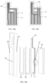
- FIG. 26a is a schematic structural diagram of a middle frame of an electronic device according to an embodiment of this application.
- FIG. 26b is a schematic structural diagram illustrating mounting of a middle frame of an electronic device and a vapor chamber according to an embodiment of this application.
- FIG. 26c is a cross-sectional view of a middle frame of an electronic device according to an embodiment of this application.
- the electronic device further includes a middle frame 200 and a display screen, where a through-hole 201 is provided in the middle frame, the vapor chamber 100 is embedded in the through-hole 201, and the vapor chamber 100 and the middle frame 200 jointly bear the display screen.
- the large area vapor chamber becomes a trend in technological development.
- the ultra-thin vapor chamber with a thickness less than or equal to 0.8 mm is generally provided, and a wall thickness of a cover plate of the vapor chamber is less than or equal to 0.2 mm.
- a conventional material is copper and copper alloy, and an ultra-thin large area and large span vapor chamber module is prone to surface flatness problems such as pits and creases and greatly deteriorates compared with a conventional small area vapor chamber, causing large decrease of yield of the vapor chamber module and large increase of costs.
- a surface hardness of the vapor chamber is less than or equal to 90 Hv and does not meet production and reliability design requirements.
- the large area vapor chamber is limited by bearing structural strength of the vapor chamber during application, for example, located between a screen display module and a battery module. Because mechanical indicators (especially elasticity modulus and surface hardness) of stainless steel, titanium, and titanium alloy are far greater than those of common copper or copper alloy material in an existing industry, problems such as pits, creases, and prone plastic deformation under force may be effectively mitigated.
- the entire device reaches or approaches a natural cooling limit, to support cooling requirements in working conditions such as high performance gaming, photographing, and ultra-high power charging.
- the vapor chamber and the middle frame may be of a serial stack structure, and the entire device is, however, thickened obviously. Moreover, the large area vapor chamber that hardly functions to meet evaporation and condensation requirements and that does not effectively improve cooling capability does not meet a product competitiveness requirement. To reduce the thickness of the entire device, a hole may be provided in part or all of the middle frame, and the vapor chamber is disposed in the hole.
- the middle frame with a large battery compartment area hollowed out is provided with strength only by a middle frame side wall, causing a great decline of strength, and especially for a 3D screen modeling and a widened 5G antenna gap, the side wall is thinned, continuity of the middle frame side wall is broken, and three-rod bending strength does not reach the standard and is difficult to optimize or reinforce.
- the large area vapor chamber is in a cantilever beam state in the middle frame, and the vapor chamber is prone to deformation and relatively poor in flatness after being welded, bringing a risk of falling crush to a screen of the electronic device.
- each are an assembly schematic exploded view of a mobile terminal according to an embodiment of this application.
- this embodiment further provides a mobile terminal, including a middle frame 200, a display screen 300, a vapor chamber 100, one or more circuit boards 400, a battery 500, a rear housing 600, and the like.
- the mobile terminal may be provided with two or more batteries, circuit boards, and the like.
- the middle frame 200 as a structural member has a supporting function.
- a through-hole 201 is provided in the middle frame 200, the vapor chamber 100 is embedded in the through-hole 201, and the vapor chamber 100 and the middle frame 200 are fixedly connected into a whole and configured to jointly bear the display screen 300, the circuit board 400, the battery 500, and the like.
- the mobile terminal may be a mobile phone, a tablet computer, a curved screen mobile phone, a folding mobile phone, or the like. This is not limited herein.
- an area of the through-hole 201 of the middle frame 200 accounts for more than 1/3 of a total area of the middle frame, or an area of the through-hole 201 is more than 70% of an area of the battery 500.
- the size and shape of the through-hole 201 may also be adjusted based on actual needs. This is not limited herein. It should be noted that the through-hole 201 is provided in part or all of the middle frame, causing a decline of structural strength of the middle frame, the vapor chamber 100 is disposed in the through-hole 201, and the vapor chamber 100 cooperates with the middle frame to support the display screen 300, the circuit board 400, the battery 500, or other components required by other mobile terminals, so that overall structural stability of the mobile terminal can be improved.
- a PCB 400 that carries a heating device is sandwiched between the vapor chamber 100 and a cooling material 701 such as a high thermal conductivity graphene film/extremely-thin vapor chamber to form sandwich cooling, so that stronger natural cooling capability under a same thickness can be implemented.
- the heating device mainly refers to a central processing unit (central processing unit, CPU), a graphics processing unit (Graphics Processing Unit, GPU), an application processor (Application Processor, AP), or other main heating devices.
- the mobile terminal further includes a cooling layer 701 and a heating device, where the cooling layer 701 is disposed on an inner side of the rear housing 600.
- the heating device is sandwiched between the vapor chamber 100 and the cooling layer 701 to form a sandwich cooling structure, so as to implement stronger natural cooling capability.
- a material of the cooling layer 701 may be a non-bearing material such as high thermal conductivity graphene or extremely-thin vapor chamber. It may be understood that, in an actual application process, the middle frame 200 and the vapor chamber 100 still serve as a load-bearing supporting member, and the sandwich cooling structure is also applied, so that stronger natural cooling capability under a same thickness can be implemented.
- a connection manner of the vapor chamber 100 and the middle frame 200 includes any one or more of riveting, bonding, welding, lapping, and metal over-molding.
- Two side surfaces are provided on the vapor chamber 100, including a battery surface 501 facing towards the battery 500 and a display surface 301 facing towards the display screen 300, where the display screen 300 and the battery 500 are disposed on two sides of the vapor chamber 100 in parallel respectively, and the display screen 300 and the display surface 301 are parallel without contact.
- the battery 500 and the battery surface 501 are parallel without contact, or the battery 500 is fixed to the battery surface 501 through back glue bonding or the like. This is not limited herein.
- Material such as graphite film, foam, glue, or flexible printed circuit (Flexible Printed Circuit, FPC) may be attached to surfaces of a display screen 300 module, a vapor chamber 100 module, and a battery 500 module.
- the vapor chamber 100 is located between the sensitive display screen 300 module and the battery 500 module.
- the vapor chamber of special structural design meets reliability and safety design requirements of the display screen, the battery and electrical connection structures of the mobile terminal, so as to implement cooling design that the ultra-thin vapor chamber fully covers the key heating device.
- the circuit board 400 may be fixed to a side of the middle frame 200 away from the display screen 300 by using a screw or a plastic buckle.
- the middle frame 200 protects and bears the circuit board 400. Heat generated by the circuit board 400 may be conducted to the vapor chamber 100.
- the rear housing 600 is located on a side of the battery 500 away from the middle frame 200.
- the mobile terminal may alternatively be a folding mobile phone.
- the display screen 300 and the battery 500 are disposed on two sides of the vapor chamber 100 in parallel respectively, and the display screen 300 and the display surface 301 are parallel without contact.
- the battery 500 and the battery surface 501 are parallel without contact, or the battery 500 is fixed to the battery surface 501 through back glue bonding or the like. This is not limited herein.
- "parallel" may indicate that an upper surface and a lower surface are equidistantly parallel in a bent state.
- the display screen and the battery are on the two sides of the vapor chamber in parallel respectively and the display screen is not in direct contact with the vapor chamber, so that the display screen can be prevented from adverse effects caused by localized deformation of the vapor chamber, and stability of the entire mobile terminal is kept.
- the vapor chamber 100 can directly bear a part of a supporting function of the middle frame.
- heat generated by the circuit board 400 may be conducted to the vapor chamber 100.
- the middle frame 200 that is provided with the through-hole 201 and the vapor chamber 100 that is embedded in the middle frame 200 are arranged as a parallel structure.
- a serial structure is that the middle frame 200 is not provided with a through-hole that is corresponding to the vapor chamber and the vapor chamber 100 is attached to the entity middle frame 200. Even with recessing and partial embedding, the serial structure is still thicker than the parallel structure, meaning that ultra-thin design of the mobile terminal is unachievable.
- a conventional vapor chamber may be applied.
- the vapor chamber for the parallel structure has various performance far better than an ordinary copper alloy vapor chamber in a serial structure middle frame assembly, so that strength, surface hardness, and reliability of the vapor chamber can be improved, thereby improving stability and reliability of the entire middle frame. If the strength of the vapor chamber 100 is insufficient, the vapor chamber 100 deforms and warps under external force after long-term use and is in contact with the display screen 300. This breaks a parallel relationship of the display surface 301 and the display screen 300, thereby affecting a display effect and causing blue spots, white spots, and the like. In addition, the vapor chamber 100 may also be easily in contact with the battery 500.
- the vapor chamber 100 made of the high-strength composite material can improve use stability of the entire mobile terminal.
- FIG. 27 is a schematic diagram illustrating strength test of a middle frame according to an embodiment of this application.
- the vapor chamber 100 in this application that cooperates with the middle frame 200 to serve as a structural supporting member and that has three-rod bending strength ranging from 100 N/mm to 120 N/mm can be configured to bear the display screen and the battery.
- an area of the evaporation region of the vapor chamber 100 that is in contact with the heat source is smaller than an area of the condensation region that is in contact with a comparatively cold region, so that the capillary structure 30 is densely arranged in the small area evaporation region and comparatively sparsely arranged in the large area condensation region.
- the evaporation region of the vapor chamber 100 abuts against the heating device of the mobile terminal (for example, circuit board 400, CPU, GPU, or AP), and the condensation region of the vapor chamber 100 may abut against the battery 500 of the mobile terminal.
- the cooling medium in the evaporation region is evaporated into vapor, the vapor flows through the vapor channel in the vapor chamber towards the condensation region, and the condensed cooling medium flows back into the evaporation region under the action of the capillary structure in the vapor chamber.
- the capillary structure 30 radiates to the condensation region from the evaporation region in contact with the heat source, so as to ensure that the cooling medium in the condensation region can flow back to the evaporation region.
- the vapor chamber 100 is provided with a mounting recess 71 and/or a mounting hole 72 in a thickness direction, where the mounting recess 71 and/or the mounting hole 72 are/is configured to mount the electronic component, and the electronic component may be, for example, a flexible printed circuit, a fingerprint module, or a screen module. It should be noted that the electronic component herein may be a heating device or a non-heating device.
- the capillary structure (liquid absorption core) in the vapor chamber is arranged at equal intervals.
- a plurality of heat sources are provided in the mobile terminal, so that a plurality of evaporation regions are provided and are not interconnected, hindering the cooling medium from flowing back to the evaporation region from the condensation region. Therefore, it is difficult to ensure that the cooling medium returns to the evaporation region in which the heat source is located, and cooling performance of the large area vapor chamber is reduced.
- the capillary structure 30 in the vapor chamber includes a first capillary structure 31 and a second capillary structure 32, where the first capillary structure 31 is at least one of copper powder, foamy copper, and copper mesh, and is flat laid on an inner surface of the first cover plate 10 and/or the second cover plate 20.
- the second capillary structure 32 is copper fiber, and is disposed in the sealed cavity 40 in a fibrous extending and dispersing manner.
- the second capillary structure 32 radiates to the condensation region from a plurality of evaporation regions.
- the capillary structure keeps a continuous state and the capillary structure is prevented from being blocked by a mounting hole 72 or a mounting recess 71 of the vapor chamber 100, so as to ensure that the cooling medium of the condensation region can flow back to the evaporation region.
- the second capillary structure 32 is densely arranged in the small area evaporation region and comparatively sparsely arranged in the large area condensation region, so as to improve cooling performance of the vapor chamber 100.
- FIG. 29a is a schematic exploded view of a middle frame of a mobile terminal according to this application.
- the middle frame 200 includes a middle frame side wall 202 and a middle frame extension member 203 connected to the middle frame side wall 202, where the middle frame extension member 203 is configured to optimize and reinforce a high stress region of the middle frame 200.
- the middle frame 200 includes four side walls 202, including two first side walls in a length direction of the mobile terminal and two second side walls in a width direction of the mobile terminal.
- the middle frame extension member 203 is connected to the two first side walls and one of the second side walls.
- the middle frame extension member 203 is connected to a side of the middle frame side wall 202 facing towards the through-hole 201.
- a material of the middle frame extension member 203 may be metal or alloy material such as aluminum alloy, stainless steel, titanium alloy, or copper alloy.
- the middle frame extension member 203 may construct an I-shaped reinforcing structure for the middle frame and can, as compared to the middle frame side wall 202 alone for supporting, greatly improve overall rigidity and strength of the middle frame, improve torsional stiffness and impact stiffness of the middle frame, and stably support the battery, the display screen, and the like on two sides of the middle frame.
- the middle frame extension member 203 and the middle frame side wall 202 are integrally machined, or the middle frame extension member 203 and the middle frame side wall 202 are separately machined and molded, and then fixedly connected through injection molding, screwing, welding, bonding, or the like.
- an extension length of the middle frame extension member 203 in the width direction of the mobile terminal ranges from 0.5 mm to 50 mm, and an extension length in the length direction of the mobile terminal ranges from 0.5 mm to 50 mm, specifically may be 0.5 mm, 1.0 mm, 2.0 mm, 5.0 mm, 10 mm, 20 mm, 30 mm, 50 mm, or the like, and may be adjusted based on specific actual needs.
- a thickness of the middle frame extension member 203 is less than a thickness of the middle frame side wall 202.
- the vapor chamber 100 further includes a step fixing part 60 formed by extending along at least a part of an edge of the vapor chamber.
- a sum of a thickness of the middle frame extension member 203 and a thickness of the step fixing part 60 is greater than or equal to a thickness of the vapor chamber 100.
- an edge of the first cover plate 10 extends to form the step fixing part 60, and the step fixing part 60 is connected to the middle frame extension member 203.
- the first cover plate 11 is made of a high-strength composite material.
- the second cover plate 20 is made of copper or copper alloy, or the second cover plate 12 may be made of a high-strength composite material.
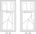
- FIG. 30a to FIG. 30d each are a schematic state diagram illustrating distribution of a middle frame extension member of a mobile terminal according to an embodiment of this application.
- the middle frame extension member 203 may be rectangular frame shaped, U-type frame shaped, or other irregular shaped.
- the middle frame extension member 203 may be a regular continuous straight side, where the continuous straight side may be arranged by equal or unequal width; or the middle frame extension member 203 may be a discontinuous straight side, where the discontinuous straight side may also be arranged by equal or unequal width; or the middle frame extension member 203 may be partially optimized and reinforced to an irregular shape based on requirements for strength and stress of the middle frame. This is not limited herein.
- FIG. 31a and FIG. 31b each are a schematic state diagram illustrating distribution of electrical connection points on a middle frame of a mobile terminal according to an embodiment of this application.
- several electrical connection points 204 are arranged on the middle frame extension member 203 and/or the step fixing part 60, where an implementation manner of the electrical connection points may be a conductive medium such as conductive adhesive or gild reed, the electrical connection points may be square, circular, rhombus, rectangular, or the like, and the middle frame extension member may be connected to the electrical connection points through riveting, welding, or the like, so that the middle frame is electrically connected to other electronic component.
- the electrical connection points 204 may be arranged discontinuously in series or arranged in parallel. This is not limited herein.
- an insulation protection layer 205 is provided on a region of the middle frame extension member 203 and/or the step fixing part 60 outside the electrical connection points, where interface resistance of the insulation protection layer 205 is greater than 500 ⁇ .
- a region may be covered through anodizing, ink, nonmetallic organic matter, or the like to form the insulation protection layer 205.
- the mobile terminal further includes a connecting layer 700 for connecting the step fixing part 60 of the vapor chamber 100 and the middle frame extension member 203, where the connecting layer 700 may be a bonding layer, a welding layer, or the like.
- a sum of a thickness of the middle frame extension member 203, a thickness of the connecting layer 700, and a thickness of the step fixing part 60 is greater than or equal to a thickness of the vapor chamber 100.
- a battery compartment cooperating with the cover plate of the vapor chamber 100 is fixed to a partial structure of the middle frame through screwing, welding, dispensing, or the like.
- the vapor chamber 100 is connected to the middle frame extension member 203 by using the step fixing part 60, and specifically may be fixed to the middle frame extension member 203 through dispensing, welding, riveting, or the like, so that the vapor chamber 100 and the middle frame 200 are connected into a whole.
- the circuit board 400 and the battery 500 are flat laid on a surface of a side of the cover plate of the vapor chamber 100 away from the middle frame extension member 203.
- FIG. 32a and FIG. 32b each are a partial schematic exploded view of a middle frame of a mobile terminal and a vapor chamber according to an embodiment of this application.
- the connecting layer 700 may be disposed on a surface of the step fixing part 60 of the vapor chamber 100 facing towards the middle frame extension member 203, so as to more stably connect the middle frame extension member 203 and the vapor chamber 100.
- the connecting layer 700 may include a first connecting layer 701 and a second connecting layer 702, where the first connecting layer 701 is disposed on a surface of the step fixing part 60 of the vapor chamber 100 facing towards the middle frame extension member 203, and is corresponding to a battery 500 arrangement region of the vapor chamber 100.
- the second connecting layer 702 is disposed on a surface of the step fixing part 60 of the vapor chamber 100 away from the middle frame extension member 203, and is corresponding to a circuit board 400 arrangement region of the vapor chamber 100.
- an overhang region of the battery (a region 6 mm to 10 mm long from a head edge or a tail edge of the battery is an overhang region of the battery) has a segment difference greater than 0.05 mm and is located on a hollowed-out edge of the middle frame, so that complete control over a sharp edge of a metal material is not guaranteed, and the battery 500 is prone to problems such as indentations, bumps or even punctures in high temperature, high humidity and falling process, causing short circuit fire.
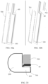
- FIG. 33 is a schematic structural diagram of a neighboring position of a middle frame and a vapor chamber according to an embodiment of this application.
- slight edge pressing design such as arc/chamfer transition or arc/chamber composite edge folding is applied to an edge of the step fixing part 60 of the vapor chamber 100 that is in contact with the middle frame side wall 202, so that the contact edge is lower than a largest side, where an arc edge radius ranges from 0.05 mm to 1 mm. Therefore, the overhang region of the battery can be effectively protected against external force, and safety of the battery is effectively protected.
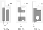
- FIG. 34a to FIG. 34c each are a schematic structural diagram illustrating connection of a vapor chamber and a battery according to an embodiment of this application.
- the battery 500 may be attached and fixed to a surface of a side of the vapor chamber 100 away from the middle frame extension member 203 by using battery adhesive 501, where the battery adhesive does not need to be provided on the middle frame side wall 202 or a battery cover, the middle frame side wall and the battery cover are not load-bearing members of the battery 500, and the middle frame 200 and the vapor chamber 100 may serve as load-bearing members of the battery 500.
- an arrangement region of the battery adhesive on the vapor chamber 100 may be adjusted based on mounting requirements of all electronic components in the mobile terminal.
- the battery adhesive may be regular shaped or irregular shaped, may be one-piece battery adhesive, or may be spliced battery adhesive. This is not limited herein.
- a hole or a slot may be provided in the one-piece battery adhesive based on requirements of the component such as a flexible printed circuit, a fingerprint module, or a screen device, so as to be adapted to stacking and inserting of the electronic component.
Landscapes
- Engineering & Computer Science (AREA)
- Microelectronics & Electronic Packaging (AREA)
- Physics & Mathematics (AREA)
- Thermal Sciences (AREA)
- Theoretical Computer Science (AREA)
- General Physics & Mathematics (AREA)
- General Engineering & Computer Science (AREA)
- Human Computer Interaction (AREA)
- Signal Processing (AREA)
- Cooling Or The Like Of Electrical Apparatus (AREA)
- Cooling Or The Like Of Semiconductors Or Solid State Devices (AREA)
- Telephone Set Structure (AREA)
- Casings For Electric Apparatus (AREA)
- Battery Mounting, Suspending (AREA)
Claims (13)
- Chambre à vapeur, dans laquelle la chambre à vapeur comprend :un boîtier (110), dans laquelle le boîtier (110) comprend une première plaque de couverture (10) et une seconde plaque de couverture (20), la première plaque de couverture (10) et la seconde plaque de couverture (20) sont reliées de manière étanche pour former une cavité étanche, un intérieur de la cavité étanche est un environnement de pression négative, et un milieu de refroidissement est prévu ; etune structure capillaire (30), dans laquelle la structure capillaire (30) est disposée dans la cavité étanche ;un matériau de la première plaque de couverture (10) et/ou de la seconde plaque de couverture (20) est un matériau composite à haute résistance, le matériau composite à haute résistance comprend une première couche de matériau (11) et une seconde couche de matériau (12), dans laquelle un matériau de la première couche de matériau (11) est au moins l'un parmi l'acier inoxydable, le titane, l'alliage de titane, le tungstène, l'alliage de tungstène, le chrome et l'alliage de chrome, et un matériau de la seconde couche de matériau (12) est du cuivre ou un alliage de cuivre ; et la seconde couche de matériau (12) est située sur un côté interne du boîtier (110) pour séparer la première couche de matériau (11) du milieu de refroidissement ;la chambre à vapeur comprend en outre une structure de support (50), et la structure de support (50) s'étend depuis une surface interne du boîtier (110) jusqu'à un espace interne du boîtier (110) ;caractérisée en ce que un matériau d'un coeur interne (51) de la structure de support (50) est le matériau de la première couche de matériau (11), et un matériau d'une périphérie de la structure de support (50) est le matériau de la seconde couche de matériau (12).
- Chambre à vapeur selon la revendication 1, dans laquelle la structure de support (50) vient en butée contre la première plaque de couverture (10) et/ou la seconde plaque de couverture (20).
- Chambre à vapeur selon l'une quelconque des revendications 1 à 2, dans laquelle la structure de support (50) et le boîtier (110) sont une structure intégrée, et la structure de support (50) est une pluralité de colonnes ou de points en saillie disposés dans un réseau.
- Chambre à vapeur selon l'une quelconque des revendications 1 à 3, dans laquelle la seconde couche de matériau (12) de la première plaque de couverture (10) et la seconde couche de matériau (12) de la seconde plaque de couverture (20) entourent la cavité étanche.
- Chambre à vapeur selon l'une quelconque des revendications 1 à 4, dans laquelle la structure capillaire (30) est un milieu métallique poreux.
- Chambre à vapeur selon la revendication 5, dans laquelle la structure capillaire (30) est un ou plusieurs parmi un maillage de cuivre, une fibre de cuivre, une poudre de cuivre, ou un cuivre mousseux.
- Chambre à vapeur selon l'une quelconque des revendications 1 à 6, dans laquelle la structure capillaire (30) est disposée sur la seconde couche de matériau (12) de la première plaque de couverture (10) et/ou de la seconde plaque de couverture (20).
- Terminal mobile, comprenant un cadre central, un écran d'affichage, une carte de circuit et une batterie, dans lequel le terminal mobile comprend en outre une chambre à vapeur selon l'une quelconque des revendications 1 à 7 ; et
un trou traversant est prévu dans le cadre central, et la chambre à vapeur est encastrée dans le trou traversant ; et la chambre à vapeur et le cadre central portent conjointement l'écran d'affichage, la carte de circuit et la batterie. - Terminal mobile selon la revendication 8, dans lequel une manière de connexion de la chambre à vapeur et du cadre central comprend l'un quelconque ou plusieurs parmi le rivetage, le collage, le soudage, le rodage et le surmoulage métallique.
- Terminal mobile selon la revendication 8 ou 9, dans lequel le cadre central comprend une paroi latérale de cadre central et un élément d'extension de cadre central, dans lequel l'élément d'extension de cadre central est relié à un côté de la paroi latérale de cadre central tournée vers le trou traversant ; dans lequel la chambre à vapeur comprend en outre une partie de fixation en marche formée en s'étendant le long d'au moins une partie d'un bord de la chambre à vapeur, dans lequel la partie de fixation en marche est reliée à l'élément d'extension de cadre central.
- Terminal mobile selon l'une quelconque des revendications 8 à 10, dans lequel la batterie et l'écran d'affichage sont disposés sur deux côtés de la chambre à vapeur en parallèle respectivement, et la chambre à vapeur comprend une surface de batterie tournée vers la batterie et une surface d'affichage tournée vers l'écran d'affichage, dans lequel l'écran d'affichage et la surface d'affichage sont parallèles sans contact.
- Procédé de préparation d'une chambre à vapeur, dans lequel le procédé comprend :la disposition d'une seconde couche de matériau (12) sur un côté d'une première couche de matériau (11) pour former une première plaque de couverture (10) ;la disposition d'une seconde couche de matériau (12) sur un côté d'une première couche de matériau (11) pour former une seconde plaque de couverture (20), dans lequel un matériau de la première couche de matériau (11) est au moins l'un parmi l'acier inoxydable, le titane, l'alliage de titane, le tungstène, l'alliage de tungstène, le chrome et l'alliage de chrome, et un matériau de la seconde couche de matériau (12) est du cuivre ou un alliage de cuivre ;la disposition d'une structure de support (50) sur une surface interne d'un boîtier (110) pour s'étendre vers un espace interne du boîtier (110), dans lequel un matériau d'un noyau interne (51) de la structure de support (50) est le matériau de la première couche de matériau (11), et un matériau d'une périphérie de la structure de support (50) est le matériau de la seconde couche de matériau (12) ; etla disposition de la structure capillaire (30) sur la seconde couche de matériau (12) de la première plaque de couverture (10) ou la seconde couche de matériau (12) de la seconde plaque de couverture (20), la combinaison de la première plaque de couverture (10) et la seconde plaque de couverture (20) pour former le boîtier creux (110), et l'injection du milieu de refroidissement dans le boîtier (110), dans lequel la seconde couche de matériau (12) est située sur un côté interne du boîtier (110) pour séparer la première couche de matériau (11) du milieu de refroidissement, etla mise en oeuvre d'un cyclage thermique du milieu de refroidissement dans le boîtier (110) en utilisant la structure capillaire (30) et un canal à vapeur.
- Procédé de préparation d'une chambre à vapeur selon la revendication 12, dans lequel le matériau de la première couche de matériau (11) est de l'acier inoxydable, et le matériau de la seconde couche de matériau (12) est du cuivre.
Applications Claiming Priority (2)
| Application Number | Priority Date | Filing Date | Title |
|---|---|---|---|
| CN202010038900.0A CN111163621B (zh) | 2020-01-14 | 2020-01-14 | 高强度均热板及其制备方法、电子设备 |
| PCT/CN2021/071267 WO2021143674A1 (fr) | 2020-01-14 | 2021-01-12 | Terminal mobile, chambre à vapeur et son procédé de préparation, et dispositif électronique |
Publications (3)
| Publication Number | Publication Date |
|---|---|
| EP4007468A1 EP4007468A1 (fr) | 2022-06-01 |
| EP4007468A4 EP4007468A4 (fr) | 2022-12-14 |
| EP4007468B1 true EP4007468B1 (fr) | 2024-03-06 |
Family
ID=70563363
Family Applications (1)
| Application Number | Title | Priority Date | Filing Date |
|---|---|---|---|
| EP21741648.6A Active EP4007468B1 (fr) | 2020-01-14 | 2021-01-12 | Terminal mobile, chambre à vapeur et son procédé de préparation, et dispositif électronique |
Country Status (6)
| Country | Link |
|---|---|
| US (1) | US12245402B2 (fr) |
| EP (1) | EP4007468B1 (fr) |
| CN (3) | CN112996346B (fr) |
| BR (1) | BR112022013989A2 (fr) |
| MX (1) | MX2022008606A (fr) |
| WO (1) | WO2021143674A1 (fr) |
Families Citing this family (48)
| Publication number | Priority date | Publication date | Assignee | Title |
|---|---|---|---|---|
| US12523431B2 (en) | 2014-09-15 | 2026-01-13 | Kelvin Thermal Technologies, Inc. | Polymer-based microfabricated thermal ground plane |
| CN112996346B (zh) | 2020-01-14 | 2022-08-02 | 荣耀终端有限公司 | 一种均热板、移动终端 |
| WO2021188128A1 (fr) * | 2020-03-18 | 2021-09-23 | Kelvin Thermal Technologies, Inc. | Plan de masse thermique à mailles déformées |
| CN113543574B (zh) * | 2020-04-18 | 2023-03-31 | 华为技术有限公司 | 均热板及其制作方法、中框组件及其制作方法及电子设备 |
| CN111552327A (zh) * | 2020-05-15 | 2020-08-18 | 上海蔚星科技有限公司 | 基于相变材料及金属微膨胀的航天器用双驱空间热开关 |
| CN111669939A (zh) * | 2020-05-25 | 2020-09-15 | 嵊州天脉导热科技有限公司 | 一种由复合金属材料制成的均热板 |
| CN112272487A (zh) * | 2020-09-09 | 2021-01-26 | 华为机器有限公司 | 均热板、均热板的制造方法及电子设备 |
| CN114161776B (zh) * | 2020-09-10 | 2025-02-11 | 华为技术有限公司 | 均温板及其制备方法、电子设备 |
| CN112118711A (zh) * | 2020-09-18 | 2020-12-22 | 南昌欧菲显示科技有限公司 | 均热板及其制作方法及电子设备 |
| CN114340364A (zh) * | 2020-09-30 | 2022-04-12 | 北京小米移动软件有限公司 | 屏蔽罩及制作方法、电路板结构和电子设备 |
| CN112420634A (zh) * | 2020-10-26 | 2021-02-26 | 南昌航空大学 | 一种强效芯片散热结构 |
| EP4251939A4 (fr) * | 2020-11-24 | 2024-08-07 | Aselsan Elektronik Sanayi ve Ticaret Anonim Sirketi | Amélioration des performances dans un système thermique à surfaces poreuses |
| JP7593793B2 (ja) * | 2020-11-26 | 2024-12-03 | 古河電気工業株式会社 | ベーパーチャンバおよびベーパーチャンバの製造方法 |
| CN112589387B (zh) * | 2020-11-30 | 2022-07-01 | 瑞声科技(南京)有限公司 | 均温板加工方法及均温板 |
| CN112672604B (zh) * | 2020-12-22 | 2023-04-21 | Oppo(重庆)智能科技有限公司 | 均热板、外壳和电子装置 |
| CN114126333B (zh) * | 2021-03-19 | 2025-08-05 | 江西理工大学 | 一种高强度、高导热的轻薄均热板 |
| KR20220138110A (ko) * | 2021-04-05 | 2022-10-12 | 삼성전자주식회사 | 비등을 이용한 열 관리 챔버를 포함하는 전자 장치 |
| CN115708403A (zh) * | 2021-08-20 | 2023-02-21 | 华为技术有限公司 | 均热板及其制备方法、电子设备 |
| CN113734417A (zh) * | 2021-09-06 | 2021-12-03 | 上海航天精密机械研究所 | 半主动防热结构及其制造方法 |
| CN113811159A (zh) * | 2021-09-14 | 2021-12-17 | 维沃移动通信有限公司 | 电子设备的主板上盖、其制造方法及电子设备 |
| CN113991215B (zh) * | 2021-10-28 | 2024-06-25 | 深圳市顺熵科技有限公司 | 一种动力电池模块及其动力电池包和热管理方法 |
| CN115023099B (zh) * | 2021-11-10 | 2023-11-21 | 荣耀终端有限公司 | 电子设备 |
| CN113873858B (zh) | 2021-11-30 | 2022-04-22 | 荣耀终端有限公司 | 壳体和电子设备 |
| US20250056764A1 (en) * | 2021-12-17 | 2025-02-13 | 9351-0618 Québec Inc. | Heat-conducting plate |
| CN114705071B (zh) * | 2022-05-13 | 2022-09-09 | 华为技术有限公司 | 移动终端、均温板和均温板的制作方法 |
| CN115003117B (zh) * | 2022-06-08 | 2025-05-02 | Oppo广东移动通信有限公司 | 散热组件及其制备方法、电子设备 |
| CN117616244A (zh) * | 2022-06-20 | 2024-02-27 | 北京小米移动软件有限公司 | 散热组件及其制造方法、中框组件、壳体组件、终端设备 |
| CN218570720U (zh) * | 2022-08-17 | 2023-03-03 | 荣耀终端有限公司 | 均热板及电子设备 |
| CN115604983B (zh) * | 2022-09-14 | 2025-05-23 | 维沃移动通信有限公司 | 散热组件和电子设备 |
| CN115296377B (zh) * | 2022-09-30 | 2023-03-24 | 荣耀终端有限公司 | 电子设备 |
| CN115505867B (zh) * | 2022-10-25 | 2024-04-05 | 北京酷捷科技有限公司 | 一种氢气还原的不锈钢铬铜合金的制备方法和应用 |
| CN115558831B (zh) * | 2022-10-25 | 2023-08-04 | 北京酷捷科技有限公司 | 一种铬钼复合材料及其制备方法和应用 |
| CN118265241A (zh) * | 2022-12-27 | 2024-06-28 | 华为技术有限公司 | 中框组件及电子设备 |
| CN116242175A (zh) * | 2022-12-28 | 2023-06-09 | 尼得科巨仲电子(昆山)有限公司 | 一种多通道热传元件 |
| CN116140644B (zh) * | 2022-12-30 | 2025-02-25 | 上海卫星装备研究所 | 卫星用高密度热流扩热-均热构件及其制造方法 |
| CN120570074A (zh) * | 2023-01-20 | 2025-08-29 | 三星电子株式会社 | 包括用于散热的结构的电子装置 |
| CN115802728A (zh) * | 2023-01-31 | 2023-03-14 | 深圳威铂驰热技术有限公司 | 用于移动终端的真空腔均热板及其加工模具 |
| US12593693B2 (en) * | 2023-02-15 | 2026-03-31 | Taiwan Semiconductor Manufacturing Company Limited | Package lid with a vapor chamber base having an angled portion and methods for forming the same |
| CN118870715A (zh) * | 2023-04-27 | 2024-10-29 | 荣耀终端有限公司 | 均热板和电子设备 |
| WO2024228451A1 (fr) * | 2023-05-04 | 2024-11-07 | 삼성전자 주식회사 | Structure de dissipation de chaleur et dispositif électronique la comprenant |
| CN116576703B (zh) * | 2023-05-11 | 2024-08-02 | 广东思泉热管理技术有限公司 | 一种具有鱼骨状毛细结构均热板制备工艺及其产品 |
| CN118946058A (zh) * | 2023-05-12 | 2024-11-12 | 荣耀终端有限公司 | 均热板和电子设备 |
| CN117714580B (zh) * | 2023-07-21 | 2024-11-19 | 荣耀终端有限公司 | 中框及其制作方法和电子设备 |
| WO2025089805A1 (fr) * | 2023-10-24 | 2025-05-01 | 삼성전자주식회사 | Dispositif électronique comprenant des structures de dispersion de chaleur |
| CN120239208A (zh) * | 2023-12-21 | 2025-07-01 | 荣耀终端股份有限公司 | 一种均温板以及电子设备 |
| CN118510217A (zh) * | 2024-04-03 | 2024-08-16 | 华为技术有限公司 | 均温板以及电子设备 |
| WO2026010108A1 (fr) * | 2024-07-04 | 2026-01-08 | 삼성전자주식회사 | Dispositif électronique comprenant une structure pour la dissipation de chaleur |
| WO2026049501A1 (fr) * | 2024-08-27 | 2026-03-05 | 삼성전자 주식회사 | Dispositif électronique |
Family Cites Families (49)
| Publication number | Priority date | Publication date | Assignee | Title |
|---|---|---|---|---|
| JPS5941898A (ja) * | 1982-08-31 | 1984-03-08 | 松下電工株式会社 | 放熱装置 |
| JPH039552A (ja) * | 1989-06-07 | 1991-01-17 | Idemitsu Petrochem Co Ltd | 高熱伝導性部材 |
| RU2297661C2 (ru) | 2005-07-29 | 2007-04-20 | Институт теплофизики Уро РАН | Пассивная система охлаждения настольного компьютера |
| US20090040726A1 (en) * | 2007-08-09 | 2009-02-12 | Paul Hoffman | Vapor chamber structure and method for manufacturing the same |
| CN101970967A (zh) * | 2007-10-10 | 2011-02-09 | 嘉合科技有限公司 | 具有可插入式毛细结构系统的鼓形均热板 |
| CN101472450A (zh) * | 2007-12-29 | 2009-07-01 | 私立淡江大学 | 可增强支撑强度与毛细作用的均热装置 |
| CN101666586A (zh) | 2008-09-03 | 2010-03-10 | 台达电子工业股份有限公司 | 散热模块、均温元件及均温元件的制造方法 |
| CN101929818A (zh) | 2009-06-19 | 2010-12-29 | 富准精密工业(深圳)有限公司 | 均温板及其制造方法 |
| CN101927426A (zh) | 2009-06-24 | 2010-12-29 | 富准精密工业(深圳)有限公司 | 均温板及其制造方法 |
| CN101995182A (zh) | 2009-08-11 | 2011-03-30 | 和硕联合科技股份有限公司 | 均温板及其制造方法 |
| CN102019543B (zh) | 2009-09-18 | 2012-10-03 | 和硕联合科技股份有限公司 | 均温板及其制作方法 |
| CN102052864A (zh) | 2009-11-10 | 2011-05-11 | 和硕联合科技股份有限公司 | 均温板及其制造方法 |
| CN201569346U (zh) * | 2009-12-08 | 2010-09-01 | 讯凯国际股份有限公司 | 散热板 |
| CN201706933U (zh) * | 2010-06-24 | 2011-01-12 | 索士亚科技股份有限公司 | 具有复合式支撑结构的均温板 |
| CN101907416A (zh) * | 2010-07-22 | 2010-12-08 | 中绿能源科技江阴有限公司 | 散热板及其制作方法 |
| CN102623421B (zh) * | 2011-01-26 | 2015-02-04 | 奇鋐科技股份有限公司 | 微均温板结构 |
| US9063700B2 (en) * | 2012-08-31 | 2015-06-23 | Apple Inc. | Low-force gap-filling conductive structures |
| CN203337002U (zh) * | 2013-05-21 | 2013-12-11 | 泰硕电子股份有限公司 | 具有支撑结构的均温板 |
| JP2015041768A (ja) * | 2013-08-23 | 2015-03-02 | 太陽工業株式会社 | ヒートシンク |
| KR101508877B1 (ko) * | 2014-04-14 | 2015-04-07 | 김흥배 | 모세관력을 가지는 구조물이 형성된 베이퍼 챔버 |
| JP5788069B1 (ja) * | 2014-08-29 | 2015-09-30 | 古河電気工業株式会社 | 平面型ヒートパイプ |
| CN105828570A (zh) | 2015-09-24 | 2016-08-03 | 维沃移动通信有限公司 | 一种散热装置 |
| US10658624B2 (en) * | 2015-12-10 | 2020-05-19 | Intel Corporation | Electronic device having an organic light emitting display |
| CN205546375U (zh) * | 2016-02-19 | 2016-08-31 | 东莞钱锋特殊胶粘制品有限公司 | 电子装置的均温散热复合膜结构 |
| CN107306486B (zh) * | 2016-04-21 | 2023-03-24 | 奇鋐科技股份有限公司 | 整合式散热装置 |
| CN107782185A (zh) * | 2016-08-31 | 2018-03-09 | 浙江嘉熙科技有限公司 | 超薄复合材料相变抑制传热板及其制备方法 |
| CN108323137A (zh) | 2017-01-18 | 2018-07-24 | 台达电子工业股份有限公司 | 均热板 |
| RU2639635C1 (ru) | 2017-03-29 | 2017-12-21 | Общество с ограниченной ответственностью "Теркон-КТТ" (ООО "Теркон-КТТ") | Теплопередающее устройство для охлаждения электронных компонентов |
| US10314214B2 (en) | 2017-10-12 | 2019-06-04 | Getac Technology Corporation | Vapor chamber with electromagnetic shielding function |
| CN207881538U (zh) * | 2017-11-03 | 2018-09-18 | 中国科学院理化技术研究所 | 一种平板热管 |
| US20190204019A1 (en) * | 2018-01-03 | 2019-07-04 | Asia Vital Components (China) Co., Ltd. | Heat dissipation device |
| CN110365815B (zh) * | 2018-03-26 | 2021-03-30 | 华为技术有限公司 | 导热组件及终端 |
| CN208835040U (zh) * | 2018-08-17 | 2019-05-07 | 东莞市宏瑞热传科技有限公司 | 一种复合型3d均温板 |
| CN209563090U (zh) * | 2018-11-30 | 2019-10-29 | 维沃移动通信有限公司 | 终端设备 |
| CN109612316A (zh) * | 2018-12-12 | 2019-04-12 | 上海卫星装备研究所 | 薄壁均温板及其制造方法 |
| CN209643232U (zh) * | 2018-12-14 | 2019-11-15 | 奇鋐科技股份有限公司 | 中框散热结构 |
| CN110234212A (zh) * | 2019-04-01 | 2019-09-13 | Oppo广东移动通信有限公司 | 散热板、散热组件、电子装置以及散热板的制备方法 |
| TWI763989B (zh) * | 2019-04-12 | 2022-05-11 | 雙鴻科技股份有限公司 | 可撓動之均溫板 |
| CN110108139A (zh) * | 2019-04-26 | 2019-08-09 | 华南理工大学 | 一种具有支撑柱和沟槽复合结构的均热板 |
| CN210512786U (zh) * | 2019-05-10 | 2020-05-12 | 双鸿电子科技工业(昆山)有限公司 | 均温板 |
| CN110418550B (zh) * | 2019-06-25 | 2021-06-01 | 华为技术有限公司 | 均热板和折叠终端 |
| CN110440621A (zh) * | 2019-07-12 | 2019-11-12 | 华为技术有限公司 | 均热板和其制造方法及电子设备 |
| CN110285699A (zh) * | 2019-07-26 | 2019-09-27 | 联德精密材料(中国)股份有限公司 | 一种复合型均温板及其制造方法 |
| CN110402068A (zh) * | 2019-07-27 | 2019-11-01 | Oppo广东移动通信有限公司 | 电子设备及电子设备的组装方法 |
| CN210892824U (zh) * | 2019-08-19 | 2020-06-30 | 东莞仁海科技股份有限公司 | 一种改进型超薄均温板 |
| CN209894013U (zh) * | 2019-09-12 | 2020-01-03 | 爱美达(深圳)热能系统有限公司 | 一种均温板 |
| CN110678048B (zh) * | 2019-10-15 | 2024-06-11 | 航天科工微系统技术有限公司 | 一种高导热均热板结构及其制造工艺 |
| CN112996346B (zh) | 2020-01-14 | 2022-08-02 | 荣耀终端有限公司 | 一种均热板、移动终端 |
| CN111829380A (zh) * | 2020-08-21 | 2020-10-27 | 北京中石伟业科技无锡有限公司 | 一种高强轻质的超薄均热板 |
-
2020
- 2020-01-14 CN CN202110110953.3A patent/CN112996346B/zh active Active
- 2020-01-14 CN CN202010038900.0A patent/CN111163621B/zh active Active
-
2021
- 2021-01-12 US US17/755,121 patent/US12245402B2/en active Active
- 2021-01-12 MX MX2022008606A patent/MX2022008606A/es unknown
- 2021-01-12 EP EP21741648.6A patent/EP4007468B1/fr active Active
- 2021-01-12 CN CN202180000700.9A patent/CN113455116B/zh active Active
- 2021-01-12 WO PCT/CN2021/071267 patent/WO2021143674A1/fr not_active Ceased
- 2021-01-12 BR BR112022013989A patent/BR112022013989A2/pt unknown
Also Published As
| Publication number | Publication date |
|---|---|
| WO2021143674A1 (fr) | 2021-07-22 |
| CN111163621B (zh) | 2021-03-02 |
| CN113455116B (zh) | 2023-06-27 |
| BR112022013989A2 (pt) | 2022-10-11 |
| EP4007468A1 (fr) | 2022-06-01 |
| CN113455116A (zh) | 2021-09-28 |
| EP4007468A4 (fr) | 2022-12-14 |
| CN112996346A (zh) | 2021-06-18 |
| CN111163621A (zh) | 2020-05-15 |
| MX2022008606A (es) | 2022-08-11 |
| US20230019481A1 (en) | 2023-01-19 |
| US12245402B2 (en) | 2025-03-04 |
| CN112996346B (zh) | 2022-08-02 |
Similar Documents
| Publication | Publication Date | Title |
|---|---|---|
| EP4007468B1 (fr) | Terminal mobile, chambre à vapeur et son procédé de préparation, et dispositif électronique | |
| CN116321969B (zh) | 一种散热结构及电子设备 | |
| JP6707960B2 (ja) | 電子機器 | |
| US20190219219A1 (en) | Heat insulating structure body | |
| CN117529010B (zh) | 一种均热板及电子设备 | |
| WO2023216482A1 (fr) | Terminal mobile, chambre à vapeur et procédé de fabrication d'une chambre à vapeur | |
| JP2000161878A (ja) | 平面型ヒートパイプ | |
| CN114401625B (zh) | 散热模组和电子设备 | |
| JP2015132400A (ja) | ループ型ヒートパイプとその製造方法、及び電子機器 | |
| CN114466557A (zh) | 电子设备的壳体、电子设备以及电子设备的壳体制造方法 | |
| EP3971681B1 (fr) | Élément thermoconducteur et dispositif électronique | |
| HK40069826B (en) | Mobile terminal, vapor chamber and preparation method therefor, and electronic device | |
| HK40069826A (en) | Mobile terminal, vapor chamber and preparation method therefor, and electronic device | |
| RU2796496C1 (ru) | Мобильный терминал, испарительная камера и способ ее изготовления и электронное устройство | |
| TWM583041U (zh) | 均溫板 | |
| WO2025209505A1 (fr) | Chambre à vapeur et dispositif électronique | |
| US20070277962A1 (en) | Two-phase cooling system for cooling power electronic components | |
| CN216700727U (zh) | 散热件及电子设备 | |
| CN216087271U (zh) | 电子设备 | |
| CN221227823U (zh) | 电子设备 | |
| CN221829315U (zh) | 均热板及电子设备 | |
| CN111912273A (zh) | 均温板 | |
| CN119835898A (zh) | 电子设备 | |
| CN120129213A (zh) | 电子设备的中框组件及电子设备 | |
| WO2025124512A1 (fr) | Ensemble de support, module d'affichage et dispositif électronique |
Legal Events
| Date | Code | Title | Description |
|---|---|---|---|
| STAA | Information on the status of an ep patent application or granted ep patent |
Free format text: STATUS: THE INTERNATIONAL PUBLICATION HAS BEEN MADE |
|
| PUAI | Public reference made under article 153(3) epc to a published international application that has entered the european phase |
Free format text: ORIGINAL CODE: 0009012 |
|
| STAA | Information on the status of an ep patent application or granted ep patent |
Free format text: STATUS: REQUEST FOR EXAMINATION WAS MADE |
|
| 17P | Request for examination filed |
Effective date: 20220228 |
|
| AK | Designated contracting states |
Kind code of ref document: A1 Designated state(s): AL AT BE BG CH CY CZ DE DK EE ES FI FR GB GR HR HU IE IS IT LI LT LU LV MC MK MT NL NO PL PT RO RS SE SI SK SM TR |
|
| RIN1 | Information on inventor provided before grant (corrected) |
Inventor name: LIU, JIAJU Inventor name: NIU, CHENJI Inventor name: LIU, YONGLU Inventor name: CHEN, QIU Inventor name: JIN, LINFANG |
|
| REG | Reference to a national code |
Ref country code: HK Ref legal event code: DE Ref document number: 40069826 Country of ref document: HK |
|
| A4 | Supplementary search report drawn up and despatched |
Effective date: 20221115 |
|
| RIC1 | Information provided on ipc code assigned before grant |
Ipc: F28F 9/007 20060101ALI20221110BHEP Ipc: F28D 15/04 20060101ALI20221110BHEP Ipc: H05K 7/20 20060101AFI20221110BHEP |
|
| DAV | Request for validation of the european patent (deleted) | ||
| DAX | Request for extension of the european patent (deleted) | ||
| STAA | Information on the status of an ep patent application or granted ep patent |
Free format text: STATUS: EXAMINATION IS IN PROGRESS |
|
| 17Q | First examination report despatched |
Effective date: 20230621 |
|
| GRAP | Despatch of communication of intention to grant a patent |
Free format text: ORIGINAL CODE: EPIDOSNIGR1 |
|
| STAA | Information on the status of an ep patent application or granted ep patent |
Free format text: STATUS: GRANT OF PATENT IS INTENDED |
|
| INTG | Intention to grant announced |
Effective date: 20230921 |
|
| GRAS | Grant fee paid |
Free format text: ORIGINAL CODE: EPIDOSNIGR3 |
|
| GRAA | (expected) grant |
Free format text: ORIGINAL CODE: 0009210 |
|
| STAA | Information on the status of an ep patent application or granted ep patent |
Free format text: STATUS: THE PATENT HAS BEEN GRANTED |
|
| AK | Designated contracting states |
Kind code of ref document: B1 Designated state(s): AL AT BE BG CH CY CZ DE DK EE ES FI FR GB GR HR HU IE IS IT LI LT LU LV MC MK MT NL NO PL PT RO RS SE SI SK SM TR |
|
| REG | Reference to a national code |
Ref country code: CH Ref legal event code: EP |
|
| REG | Reference to a national code |
Ref country code: IE Ref legal event code: FG4D |
|
| REG | Reference to a national code |
Ref country code: DE Ref legal event code: R096 Ref document number: 602021010185 Country of ref document: DE |
|
| REG | Reference to a national code |
Ref country code: LT Ref legal event code: MG9D |
|
| REG | Reference to a national code |
Ref country code: NL Ref legal event code: FP |
|
| PG25 | Lapsed in a contracting state [announced via postgrant information from national office to epo] |
Ref country code: LT Free format text: LAPSE BECAUSE OF FAILURE TO SUBMIT A TRANSLATION OF THE DESCRIPTION OR TO PAY THE FEE WITHIN THE PRESCRIBED TIME-LIMIT Effective date: 20240306 |
|
| PG25 | Lapsed in a contracting state [announced via postgrant information from national office to epo] |
Ref country code: GR Free format text: LAPSE BECAUSE OF FAILURE TO SUBMIT A TRANSLATION OF THE DESCRIPTION OR TO PAY THE FEE WITHIN THE PRESCRIBED TIME-LIMIT Effective date: 20240607 |
|
| PG25 | Lapsed in a contracting state [announced via postgrant information from national office to epo] |
Ref country code: HR Free format text: LAPSE BECAUSE OF FAILURE TO SUBMIT A TRANSLATION OF THE DESCRIPTION OR TO PAY THE FEE WITHIN THE PRESCRIBED TIME-LIMIT Effective date: 20240306 Ref country code: RS Free format text: LAPSE BECAUSE OF FAILURE TO SUBMIT A TRANSLATION OF THE DESCRIPTION OR TO PAY THE FEE WITHIN THE PRESCRIBED TIME-LIMIT Effective date: 20240606 |
|
| PG25 | Lapsed in a contracting state [announced via postgrant information from national office to epo] |
Ref country code: ES Free format text: LAPSE BECAUSE OF FAILURE TO SUBMIT A TRANSLATION OF THE DESCRIPTION OR TO PAY THE FEE WITHIN THE PRESCRIBED TIME-LIMIT Effective date: 20240306 |
|
| PG25 | Lapsed in a contracting state [announced via postgrant information from national office to epo] |
Ref country code: RS Free format text: LAPSE BECAUSE OF FAILURE TO SUBMIT A TRANSLATION OF THE DESCRIPTION OR TO PAY THE FEE WITHIN THE PRESCRIBED TIME-LIMIT Effective date: 20240606 Ref country code: NO Free format text: LAPSE BECAUSE OF FAILURE TO SUBMIT A TRANSLATION OF THE DESCRIPTION OR TO PAY THE FEE WITHIN THE PRESCRIBED TIME-LIMIT Effective date: 20240606 Ref country code: LT Free format text: LAPSE BECAUSE OF FAILURE TO SUBMIT A TRANSLATION OF THE DESCRIPTION OR TO PAY THE FEE WITHIN THE PRESCRIBED TIME-LIMIT Effective date: 20240306 Ref country code: HR Free format text: LAPSE BECAUSE OF FAILURE TO SUBMIT A TRANSLATION OF THE DESCRIPTION OR TO PAY THE FEE WITHIN THE PRESCRIBED TIME-LIMIT Effective date: 20240306 Ref country code: GR Free format text: LAPSE BECAUSE OF FAILURE TO SUBMIT A TRANSLATION OF THE DESCRIPTION OR TO PAY THE FEE WITHIN THE PRESCRIBED TIME-LIMIT Effective date: 20240607 Ref country code: FI Free format text: LAPSE BECAUSE OF FAILURE TO SUBMIT A TRANSLATION OF THE DESCRIPTION OR TO PAY THE FEE WITHIN THE PRESCRIBED TIME-LIMIT Effective date: 20240306 Ref country code: ES Free format text: LAPSE BECAUSE OF FAILURE TO SUBMIT A TRANSLATION OF THE DESCRIPTION OR TO PAY THE FEE WITHIN THE PRESCRIBED TIME-LIMIT Effective date: 20240306 Ref country code: BG Free format text: LAPSE BECAUSE OF FAILURE TO SUBMIT A TRANSLATION OF THE DESCRIPTION OR TO PAY THE FEE WITHIN THE PRESCRIBED TIME-LIMIT Effective date: 20240306 |
|
| REG | Reference to a national code |
Ref country code: AT Ref legal event code: MK05 Ref document number: 1664803 Country of ref document: AT Kind code of ref document: T Effective date: 20240306 |
|
| PG25 | Lapsed in a contracting state [announced via postgrant information from national office to epo] |
Ref country code: SE Free format text: LAPSE BECAUSE OF FAILURE TO SUBMIT A TRANSLATION OF THE DESCRIPTION OR TO PAY THE FEE WITHIN THE PRESCRIBED TIME-LIMIT Effective date: 20240306 Ref country code: LV Free format text: LAPSE BECAUSE OF FAILURE TO SUBMIT A TRANSLATION OF THE DESCRIPTION OR TO PAY THE FEE WITHIN THE PRESCRIBED TIME-LIMIT Effective date: 20240306 |
|
| PG25 | Lapsed in a contracting state [announced via postgrant information from national office to epo] |
Ref country code: IS Free format text: LAPSE BECAUSE OF FAILURE TO SUBMIT A TRANSLATION OF THE DESCRIPTION OR TO PAY THE FEE WITHIN THE PRESCRIBED TIME-LIMIT Effective date: 20240706 |
|
| PG25 | Lapsed in a contracting state [announced via postgrant information from national office to epo] |
Ref country code: PT Free format text: LAPSE BECAUSE OF FAILURE TO SUBMIT A TRANSLATION OF THE DESCRIPTION OR TO PAY THE FEE WITHIN THE PRESCRIBED TIME-LIMIT Effective date: 20240708 Ref country code: SM Free format text: LAPSE BECAUSE OF FAILURE TO SUBMIT A TRANSLATION OF THE DESCRIPTION OR TO PAY THE FEE WITHIN THE PRESCRIBED TIME-LIMIT Effective date: 20240306 |
|
| PG25 | Lapsed in a contracting state [announced via postgrant information from national office to epo] |
Ref country code: CZ Free format text: LAPSE BECAUSE OF FAILURE TO SUBMIT A TRANSLATION OF THE DESCRIPTION OR TO PAY THE FEE WITHIN THE PRESCRIBED TIME-LIMIT Effective date: 20240306 Ref country code: EE Free format text: LAPSE BECAUSE OF FAILURE TO SUBMIT A TRANSLATION OF THE DESCRIPTION OR TO PAY THE FEE WITHIN THE PRESCRIBED TIME-LIMIT Effective date: 20240306 |
|
| PG25 | Lapsed in a contracting state [announced via postgrant information from national office to epo] |
Ref country code: AT Free format text: LAPSE BECAUSE OF FAILURE TO SUBMIT A TRANSLATION OF THE DESCRIPTION OR TO PAY THE FEE WITHIN THE PRESCRIBED TIME-LIMIT Effective date: 20240306 |
|
| PG25 | Lapsed in a contracting state [announced via postgrant information from national office to epo] |
Ref country code: PL Free format text: LAPSE BECAUSE OF FAILURE TO SUBMIT A TRANSLATION OF THE DESCRIPTION OR TO PAY THE FEE WITHIN THE PRESCRIBED TIME-LIMIT Effective date: 20240306 |
|
| PG25 | Lapsed in a contracting state [announced via postgrant information from national office to epo] |
Ref country code: SK Free format text: LAPSE BECAUSE OF FAILURE TO SUBMIT A TRANSLATION OF THE DESCRIPTION OR TO PAY THE FEE WITHIN THE PRESCRIBED TIME-LIMIT Effective date: 20240306 |
|
| PG25 | Lapsed in a contracting state [announced via postgrant information from national office to epo] |
Ref country code: SM Free format text: LAPSE BECAUSE OF FAILURE TO SUBMIT A TRANSLATION OF THE DESCRIPTION OR TO PAY THE FEE WITHIN THE PRESCRIBED TIME-LIMIT Effective date: 20240306 Ref country code: SK Free format text: LAPSE BECAUSE OF FAILURE TO SUBMIT A TRANSLATION OF THE DESCRIPTION OR TO PAY THE FEE WITHIN THE PRESCRIBED TIME-LIMIT Effective date: 20240306 Ref country code: RO Free format text: LAPSE BECAUSE OF FAILURE TO SUBMIT A TRANSLATION OF THE DESCRIPTION OR TO PAY THE FEE WITHIN THE PRESCRIBED TIME-LIMIT Effective date: 20240306 Ref country code: PT Free format text: LAPSE BECAUSE OF FAILURE TO SUBMIT A TRANSLATION OF THE DESCRIPTION OR TO PAY THE FEE WITHIN THE PRESCRIBED TIME-LIMIT Effective date: 20240708 Ref country code: PL Free format text: LAPSE BECAUSE OF FAILURE TO SUBMIT A TRANSLATION OF THE DESCRIPTION OR TO PAY THE FEE WITHIN THE PRESCRIBED TIME-LIMIT Effective date: 20240306 Ref country code: IS Free format text: LAPSE BECAUSE OF FAILURE TO SUBMIT A TRANSLATION OF THE DESCRIPTION OR TO PAY THE FEE WITHIN THE PRESCRIBED TIME-LIMIT Effective date: 20240706 Ref country code: EE Free format text: LAPSE BECAUSE OF FAILURE TO SUBMIT A TRANSLATION OF THE DESCRIPTION OR TO PAY THE FEE WITHIN THE PRESCRIBED TIME-LIMIT Effective date: 20240306 Ref country code: CZ Free format text: LAPSE BECAUSE OF FAILURE TO SUBMIT A TRANSLATION OF THE DESCRIPTION OR TO PAY THE FEE WITHIN THE PRESCRIBED TIME-LIMIT Effective date: 20240306 Ref country code: AT Free format text: LAPSE BECAUSE OF FAILURE TO SUBMIT A TRANSLATION OF THE DESCRIPTION OR TO PAY THE FEE WITHIN THE PRESCRIBED TIME-LIMIT Effective date: 20240306 |
|
| PG25 | Lapsed in a contracting state [announced via postgrant information from national office to epo] |
Ref country code: IT Free format text: LAPSE BECAUSE OF FAILURE TO SUBMIT A TRANSLATION OF THE DESCRIPTION OR TO PAY THE FEE WITHIN THE PRESCRIBED TIME-LIMIT Effective date: 20240306 |
|
| REG | Reference to a national code |
Ref country code: DE Ref legal event code: R097 Ref document number: 602021010185 Country of ref document: DE |
|
| PG25 | Lapsed in a contracting state [announced via postgrant information from national office to epo] |
Ref country code: IT Free format text: LAPSE BECAUSE OF FAILURE TO SUBMIT A TRANSLATION OF THE DESCRIPTION OR TO PAY THE FEE WITHIN THE PRESCRIBED TIME-LIMIT Effective date: 20240306 |
|
| PLBE | No opposition filed within time limit |
Free format text: ORIGINAL CODE: 0009261 |
|
| STAA | Information on the status of an ep patent application or granted ep patent |
Free format text: STATUS: NO OPPOSITION FILED WITHIN TIME LIMIT |
|
| PG25 | Lapsed in a contracting state [announced via postgrant information from national office to epo] |
Ref country code: DK Free format text: LAPSE BECAUSE OF FAILURE TO SUBMIT A TRANSLATION OF THE DESCRIPTION OR TO PAY THE FEE WITHIN THE PRESCRIBED TIME-LIMIT Effective date: 20240306 |
|
| PG25 | Lapsed in a contracting state [announced via postgrant information from national office to epo] |
Ref country code: DK Free format text: LAPSE BECAUSE OF FAILURE TO SUBMIT A TRANSLATION OF THE DESCRIPTION OR TO PAY THE FEE WITHIN THE PRESCRIBED TIME-LIMIT Effective date: 20240306 |
|
| 26N | No opposition filed |
Effective date: 20241209 |
|
| PG25 | Lapsed in a contracting state [announced via postgrant information from national office to epo] |
Ref country code: SI Free format text: LAPSE BECAUSE OF FAILURE TO SUBMIT A TRANSLATION OF THE DESCRIPTION OR TO PAY THE FEE WITHIN THE PRESCRIBED TIME-LIMIT Effective date: 20240306 |
|
| REG | Reference to a national code |
Ref country code: CH Ref legal event code: PL |
|
| PG25 | Lapsed in a contracting state [announced via postgrant information from national office to epo] |
Ref country code: MC Free format text: LAPSE BECAUSE OF FAILURE TO SUBMIT A TRANSLATION OF THE DESCRIPTION OR TO PAY THE FEE WITHIN THE PRESCRIBED TIME-LIMIT Effective date: 20240306 Ref country code: LU Free format text: LAPSE BECAUSE OF NON-PAYMENT OF DUE FEES Effective date: 20250112 |
|
| PG25 | Lapsed in a contracting state [announced via postgrant information from national office to epo] |
Ref country code: BE Free format text: LAPSE BECAUSE OF NON-PAYMENT OF DUE FEES Effective date: 20250131 |
|
| PG25 | Lapsed in a contracting state [announced via postgrant information from national office to epo] |
Ref country code: FR Free format text: LAPSE BECAUSE OF NON-PAYMENT OF DUE FEES Effective date: 20250131 |
|
| PG25 | Lapsed in a contracting state [announced via postgrant information from national office to epo] |
Ref country code: CH Free format text: LAPSE BECAUSE OF NON-PAYMENT OF DUE FEES Effective date: 20250131 |
|
| REG | Reference to a national code |
Ref country code: BE Ref legal event code: MM Effective date: 20250131 |
|
| PGFP | Annual fee paid to national office [announced via postgrant information from national office to epo] |
Ref country code: GB Payment date: 20251204 Year of fee payment: 6 |
|
| PGFP | Annual fee paid to national office [announced via postgrant information from national office to epo] |
Ref country code: NL Payment date: 20251215 Year of fee payment: 6 |
|
| PG25 | Lapsed in a contracting state [announced via postgrant information from national office to epo] |
Ref country code: IE Free format text: LAPSE BECAUSE OF NON-PAYMENT OF DUE FEES Effective date: 20250112 |
|
| PGFP | Annual fee paid to national office [announced via postgrant information from national office to epo] |
Ref country code: DE Payment date: 20251203 Year of fee payment: 6 |