EP4007514B1 - Appareil de fermeture pour un récipient sous pression, récipient sous pression et utilisation de l'appareil de fermeture - Google Patents
Appareil de fermeture pour un récipient sous pression, récipient sous pression et utilisation de l'appareil de fermeture Download PDFInfo
- Publication number
- EP4007514B1 EP4007514B1 EP20736609.7A EP20736609A EP4007514B1 EP 4007514 B1 EP4007514 B1 EP 4007514B1 EP 20736609 A EP20736609 A EP 20736609A EP 4007514 B1 EP4007514 B1 EP 4007514B1
- Authority
- EP
- European Patent Office
- Prior art keywords
- pressure vessel
- outer body
- pressure
- closing device
- central body
- Prior art date
- Legal status (The legal status is an assumption and is not a legal conclusion. Google has not performed a legal analysis and makes no representation as to the accuracy of the status listed.)
- Active
Links
Images



Classifications
-
- A—HUMAN NECESSITIES
- A47—FURNITURE; DOMESTIC ARTICLES OR APPLIANCES; COFFEE MILLS; SPICE MILLS; SUCTION CLEANERS IN GENERAL
- A47J—KITCHEN EQUIPMENT; COFFEE MILLS; SPICE MILLS; APPARATUS FOR MAKING BEVERAGES
- A47J27/00—Cooking-vessels
- A47J27/08—Pressure-cookers; Lids or locking devices specially adapted therefor
- A47J27/09—Safety devices
-
- A—HUMAN NECESSITIES
- A47—FURNITURE; DOMESTIC ARTICLES OR APPLIANCES; COFFEE MILLS; SPICE MILLS; SUCTION CLEANERS IN GENERAL
- A47J—KITCHEN EQUIPMENT; COFFEE MILLS; SPICE MILLS; APPARATUS FOR MAKING BEVERAGES
- A47J27/00—Cooking-vessels
- A47J27/08—Pressure-cookers; Lids or locking devices specially adapted therefor
- A47J27/09—Safety devices
- A47J27/092—Devices for automatically releasing pressure before opening
-
- A—HUMAN NECESSITIES
- A47—FURNITURE; DOMESTIC ARTICLES OR APPLIANCES; COFFEE MILLS; SPICE MILLS; SUCTION CLEANERS IN GENERAL
- A47J—KITCHEN EQUIPMENT; COFFEE MILLS; SPICE MILLS; APPARATUS FOR MAKING BEVERAGES
- A47J27/00—Cooking-vessels
- A47J27/08—Pressure-cookers; Lids or locking devices specially adapted therefor
- A47J27/0804—Locking devices
-
- A—HUMAN NECESSITIES
- A47—FURNITURE; DOMESTIC ARTICLES OR APPLIANCES; COFFEE MILLS; SPICE MILLS; SUCTION CLEANERS IN GENERAL
- A47J—KITCHEN EQUIPMENT; COFFEE MILLS; SPICE MILLS; APPARATUS FOR MAKING BEVERAGES
- A47J36/00—Parts, details or accessories of cooking-vessels
- A47J36/38—Parts, details or accessories of cooking-vessels for withdrawing or condensing cooking vapors from cooking utensils
Definitions
- a locking device for a pressure vessel (eg for a pressure cooker) is provided which offers the user a greater degree of safety, in particular corresponds to the essential safety requirements from Annex I of Directive 2014/68/EU.
- the closure device is equipped with a lock that prevents the pressure vessel from opening at an internal pressure of ⁇ 4 kPa, even in the event of counter-pressure being exerted on the closure device in the direction of the pressure vessel.
- the closure device has an outer body that surrounds a central body of the closure device and is movably connected to it.
- the outer body is at a specific distance (x) from the central body along a cylinder axis of the outer body, and locking arms of the central body can be moved at least by the specific distance (x) along the cylinder axis of the outer body through recesses in the outer body.
- the built-in residual pressure safety device is designed as a locking arm with locking hooks and is coupled directly to the cooking indicator (see Fig figure 1 ). As long as there is a residual pressure of ⁇ 4 kPa in the pressure cooker, this is visualized by the cooking display and mechanically locked at the same time. With such pressure vessels, however, it cannot be ruled out that the residual pressure safety device may be manipulated by deliberately pressing down on the cooking indicator, and thus the mechanical locking is also canceled for pressures ⁇ 4 kPa, which also means that the pressure vessel opens with a residual pressure of ⁇ 4 kPa in the pressure vessel Pressure vessel allows.
- the CN 109 157 127 A discloses a steam valve and a cooking utensil with the steam valve.
- the steam valve includes a steam valve cap provided with an air inlet for inflow of steam and an air outlet for outflow of steam, and a valve core assembly disposed inside the steam valve cap.
- a closure device for a pressure vessel which no longer has the disadvantages observed in the prior art, ie which ensures that even with a residual pressure of ⁇ 4 kPa in the pressure vessel
- the pressure vessel remains closed, ie it can no longer be opened by manipulating the residual pressure safety device.
- a pressure vessel should be provided that can no longer be opened by manipulating the residual pressure safety device at a residual pressure of 4 kPa in the pressure vessel.
- uses of the locking device should be specified.
- the closure device is characterized in that it contains an essentially cylindrical outer body, the outer body being arranged at least in regions outside the central body, the outer body being movably connected to the central body, so that the central body can be moved within the outer body in the direction of a cylinder axis of the outer body ,
- the outer body has recesses through which the locking arms protrude from the central body through the outer body outwards, and the outer body in the direction of a cylinder axis of the outer body has a certain distance (x) to the central body and the low -lock arms in the direction of the cylinder axis of the outer body at least this determined distance (x) to one end of the recesses.
- the decisive advantage of the closure device according to the invention is that a pressure vessel closed with the closure device remains closed at an internal pressure of ⁇ 4 kPa, i.e. it can no longer be opened by manipulating the residual pressure safety device (e.g. by mechanically pressing the closure device in the direction of the pressure container against the internal pressure of ⁇ 4 kPa. A via the closure device The cooking signal issued to the user of the pressure vessel (optical) is thus decoupled from the residual pressure safety device provided via the closure device. This ensures that if the (optical) cooking signal of the closure device is pressed down at the same time and there is a pressure >_4 kPa inside the pressure container (e.g. a pressure cooker) it is not possible to unlock or open the pressure vessel.
- the distance x can correspond to a value in the range from 1 mm to 6 mm, preferably 1.5 mm to 5 mm, particularly preferably 2 mm to 4 mm, in particular 3 mm.
- the central body of the closure device can be formed in one piece with the inner body.
- the central body of the closure device can be plugged into the outer body via a plug-in connection.
- the outer body has a height in the direction of a cylinder axis of the outer body that is at least 2 mm, preferably at least 3 mm, greater than the height of the central body in this direction.
- the recesses of the outer body in the direction of a cylinder axis of the outer body, a Height at least 2 mm, preferably at least 3 mm, is greater than the height of the locking arms in that direction.
- the two locking arms of the central body can be integral with the central body.
- the two locking arms of the central body can each be in one piece with the locking hooks.
- the outer body has a cooking indicator.
- the substantially cylindrical central body may have a diameter ranging from 20 to 35 cm, preferably from 26 to 28 cm.
- the essentially cylindrical inner body can have a diameter in the range from 5 to 11 cm, preferably from 7 to 9 cm.
- the essentially cylindrical outer body can have a diameter in the range from 30 to 45 cm, preferably from 32 to 36 cm.
- a pressure vessel preferably a pressure cooker, is provided according to the invention, which contains a closure device according to the invention.
- the closure device according to the invention can be applied to the pressure vessel.
- the closure device according to the invention is preferably applied to the pressure vessel via the inner body of the closure device.
- the pressure vessel can be characterized in that it has one or more valve lifters, each with at least one stop edge.
- the stop edge(s) can be designed in such a way that, at a pressure of ⁇ 4 kPa inside the pressure vessel and a simultaneous, corresponding back pressure of ⁇ 4 kPa on the outer body of the closure device, they engage in the locking hooks of the locking arms of the closure device intervene / intervene.
- the stop edge(s) can be designed in such a way that they do not get into the locking hooks of the locking arms at a pressure of ⁇ 4 kPa inside the pressure vessel and optionally a simultaneous, corresponding counter-pressure of ⁇ 4 kPa on the outer body of the locking device intervene / intervene.
- the pressure vessel is characterized in that at a pressure of 0 kPa inside the pressure vessel, the central body is at a distance from the outer body, in the direction of a cylinder axis of the outer body, which is in the range from 1 mm to 6 mm, preferably 1 .5 mm to 5 mm, particularly preferably 2 mm to 4 mm, in particular 3 mm.
- the pressure vessel can be characterized in that at a pressure of 0 kPa inside the pressure vessel, the locking arms, in the direction of a cylinder axis of the outer body, are at a distance from one end of the recesses, which is preferably in the range of 1 mm to 6 mm 1.5 mm to 5 mm, particularly preferably 2 mm to 4 mm, in particular 3 mm.
- the pressure vessel has a spring which is connected to the inner body of the closure device and, at a pressure of 4 kPa inside the pressure vessel, is stretched over a distance which essentially corresponds to a distance from the central body to the outer body and/or a Distance from the locking arms to the end of the recesses preferably corresponds to an expansion distance in the range from 1 mm to 6 mm, preferably 1.5 mm to 5 mm, particularly preferably 2 mm to 4 mm, in particular 3 mm.
- closure device according to the invention for closing a pressure vessel, preferably for closing a pressure cooker, is proposed.
- FIG 1 shows a closure device known in the prior art for a pressure vessel.
- the locking device has a central body 12 containing a visual cooking indicator 9 and also two locking arms 2, 2' each having a locking hook 3, 3' at its end. Via an inner body 13 of the central body 12, the known closure device can be applied (eg slipped on) to a pressure vessel (eg a pressure cooker).
- a pressure vessel eg a pressure cooker
- FIG 2 shows a closure device known in the prior art, which is applied to a pressure vessel 5 .
- the closure device is connected to the inner body 13 with a spring 8 of the pressure vessel 5 which exerts a tensile force in the direction of the pressure vessel 5 .
- the pressure vessel 5 is not under pressure or if the internal pressure of the pressure vessel 5 is only low (see Figure 2A)
- the two locking hooks 3, 3' of the two locking arms 2, 2' of the central body 12 are not in the stop edge 11 of the valve lifter 10 of the pressure vessel 5 snaps into place and the valve lifter 10 can be released from the locking device (see arrow in Figure 2A ).
- the closure device moves away from the pressure vessel 5 until there is an equilibrium of forces.
- the internal pressure of the pressure vessel is 4 kPa (see Figure 2B )
- the two locking hooks 3, 3' of the two locking arms 2, 2' of the central body 12 have snapped into the stop edge 11 of the valve lifter 10 of the pressure vessel 5 and the valve lifter 10 can no longer be released from the closure device (see crossed-out arrow in Figure 2B ).
- FIG 3 shows a closure device according to the invention.
- the locking device according to the invention has a central body 1 containing two locking arms 2, 2', each having a locking hook 3, 3' at their end.
- the closure device can be applied (eg slipped on) to a pressure vessel (eg a pressure cooker) via an inner body 4 of the central body 1 .
- the closure device contains an outer body 6, which has an optical cooking display 9 and also two recesses 7, 7'.
- the central body 1 is introduced (e.g.
- the outer body 6 is inserted) into the outer body 6 along its cylinder axis Z and along a cylinder axis A of the outer body 6, so that the two locking arms 2, 2′ of the central body 1 protrude outwards through the two recesses 7, 7′ of the outer body (please refer Figure 3B ).
- the height H7 of the two recesses 7, 7' is greater by a certain distance Y than the height H2 of the two locking arms 2, 2' at this point.
- the distance is 1 mm to 6 mm, in particular 3mm
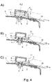
- FIG 4 shows a closure device according to the invention, which is applied to a pressure vessel 5.
- the closure device is connected to the inner body 4 with a spring 8 of the pressure vessel 5 which exerts a tensile force in the direction of the pressure vessel 5 . If the pressure vessel 5 is not pressurized or if the internal pressure of the pressure vessel 5 is only low (see Figure 4A ), the two locking hooks 3, 3' of the two locking arms 2, 2' of the central body 1 have not latched into the stop edge 11 of the valve lifter 10 of the pressure vessel 5 and the valve lifter 10 can be released from the closure device (see arrow in Figure 4A ).
- the closure device moves away from the pressure vessel 5 until the forces are balanced.
- the internal pressure of the pressure vessel 5 is 4 kPa (see Figure 4B )
- the two locking hooks 3, 3' of the two locking arms 2, 2' of the central body 12 have snapped into the stop edge 11 of the valve lifter 10 of the pressure vessel 5 and the valve lifter 10 can no longer be released from the closure device (see crossed-out arrow in Figure 4B ).
- FIG figure 5 shows an enlarged section of a locking arm 2 with locking hook 3 of a locking device according to the invention in the situation from FIG Figure 4C .
- the locking hook 3 remains locked in the stop edge 11 of the valve lifter of the pressure vessel 5 and thus prevents the valve lifter from being removed.
Landscapes
- Engineering & Computer Science (AREA)
- Food Science & Technology (AREA)
- Cookers (AREA)
- Pressure Vessels And Lids Thereof (AREA)
- Discharge Heating (AREA)
Claims (15)
- Dispositif de fermeture pour un récipient sous pression, contenanta) un corps central sensiblement cylindrique, qui présente une hauteur définie le long d'un axe de cylindre du corps central et présente, sur une surface dirigée vers l'extérieur, deux bras de verrouillage qui contiennent chacun un crochet de verrouillage ; etb) un corps intérieur sensiblement cylindrique, qui est relié au corps central, est disposé au moins par zones à l'intérieur du corps central et est adapté pour être appliqué sur une ouverture d'un récipient sous pression ;dans lequel le dispositif de fermeture comprend un corps extérieur sensiblement cylindrique, eti.) le corps extérieur est disposé au moins par zones à l'extérieur du corps central ;ii.) le corps extérieur est relié de manière mobile au corps central, de sorte que le corps central est mobile à l'intérieur du corps extérieur dans la direction d'un axe de cylindre du corps extérieur ; caractérisé en ce queiii.) le corps extérieur présente des évidements à travers lesquels les bras de verrouillage font saillie vers l'extérieur depuis le corps central à travers le corps extérieur ; etiv.) le corps extérieur présente, dans la direction d'un axe de cylindre du corps extérieur, une distance (x) définie par rapport au corps central et les bras de verrouillage présentent, dans la direction de l'axe de cylindre du corps extérieur, au moins cette distance (x) définie par rapport à une extrémité des évidements.
- Dispositif de fermeture selon la revendication 1, caractérisé en ce que la distance xi.) correspond à un trajet d'allongement d'un ressort d'un récipient sous pression à une pression interne définie du récipient sous pression, de préférence un trajet d'allongement d'un ressort d'un récipient sous pression à une pression interne du récipient sous pression dans la plage de > 0 kPa à < 4 kPa ; et/ouii.) à une valeur dans la plage de 1 mm à 6 mm, de préférence 1,5 mm à 5 mm, de manière particulièrement préférée 2 mm à 4 mm, en particulier de 3 mm.
- Dispositif de fermeture selon l'une quelconque des revendications précédentes, caractérisé en ce que le corps centrali.) est réalisé d'un seul tenant avec le corps intérieur ; et/ouii.) est enfiché dans le corps extérieur par l'intermédiaire d'une liaison enfichable.
- Dispositif de fermeture selon l'une quelconque des revendications précédentes, caractérisé en ce que, dans la direction d'un axe de cylindre du corps extérieur, le corps extérieur présente une hauteur qui est supérieure d'au moins 2 mm, de préférence d'au moins 3 mm, à la hauteur du corps central dans cette direction.
- Dispositif de fermeture selon l'une quelconque des revendications précédentes, caractérisé en ce que, dans la direction d'un axe de cylindre du corps extérieur, les évidements présentent une hauteur qui est supérieure d'au moins 2 mm, de préférence d'au moins 3 mm, à la hauteur des bras de verrouillage dans cette direction.
- Dispositif de fermeture selon l'une quelconque des revendications précédentes, caractérisé en ce que les deux bras de verrouillage du corps centrali.) sont d'un seul tenant avec le corps central ; et/ouii.) sont respectivement d'un seul tenant avec les crochets de verrouillage.
- Dispositif de fermeture selon l'une quelconque des revendications précédentes, caractérisé en ce que le corps extérieur présente un témoin de cuisson.
- Dispositif de fermeture selon l'une quelconque des revendications précédentes, caractérisé en ce que lei.) corps central sensiblement cylindrique présente un diamètre dans la plage de 20 à 35 cm, de préférence de 26 à 28 cm ; et/ouii.) corps intérieur sensiblement cylindrique présente un diamètre dans la plage de 5 à 11 cm, de préférence de 7 à 9 cm ; et/ouiii.) corps extérieur sensiblement cylindrique présente un diamètre dans la plage de 30 à 45 cm, de préférence de 32 à 36 cm.
- Récipient sous pression, de préférence autocuiseur, contenant un dispositif de fermeture selon l'une quelconque des revendications précédentes.
- Récipient sous pression selon la revendication 9, dans lequel le dispositif de fermeture selon l'une quelconque des revendications 1 à 8 est appliqué sur le récipient sous pression, de préférence est appliqué sur le récipient sous pression par l'intermédiaire du corps intérieur du dispositif de fermeture.
- Récipient sous pression selon la revendication 10, caractérisé en ce que le récipient sous pression présente un ou plusieurs lève-vannes avec chacun au moins une arête de butée, dans lequel la ou les arêtes de butée (est)sont conçue(s) de telle sorte qu'elle(s) intervienne(nt) ài.) une pression ≥ 4 kPa à l'intérieur du récipient sous pression, et une contre-pression correspondante simultanée ≥ 4 kPa sur le corps extérieur du dispositif de fermeture, s'insère/s'insèrent dans les crochets de verrouillage des bras de verrouillage du dispositif de fermeture ; et/ouii.) une pression < 4 kPa à l'intérieur du récipient sous pression, et éventuellement une contre-pression correspondante simultanée ≥ 4 kPa sur le corps extérieur du dispositif de fermeture, ne s'insère/s'insèrent pas dans les crochets de verrouillage des bras de verrouillage.
- Récipient sous pression selon l'une quelconque des revendications 10 ou 11, caractérisé en ce que, à une pression de 0 kPa à l'intérieur du récipient sous pression, le corps central présente, dans la direction d'un axe de cylindre du corps extérieur, une distance par rapport au corps extérieur qui se situe dans la plage de 1 mm à 6 mm, de préférence 1,5 mm à 5 mm, de manière particulièrement préférée 2 mm à 4 mm, en particulier de 3 mm.
- Récipient sous pression selon l'une quelconque des revendications 10 à 12, caractérisé en ce que, à une pression de 0 kPa à l'intérieur du récipient sous pression, les bras de verrouillage présentent, dans la direction d'un axe de cylindre du corps extérieur, une distance jusqu'à une extrémité des évidements qui se situe dans la plage de 1 mm à 6 mm, de préférence 1,5 mm à 5 mm, de manière particulièrement préférée 2 mm à 4 mm, en particulier de 3 mm.
- Récipient sous pression selon l'une quelconque des revendications 9 à 13, caractérisé en ce que le récipient sous pression présente un ressort qui est relié au corps intérieur du dispositif de fermeture et subit, à une pression de 4 kPa à l'intérieur du récipient sous pression, un allongement sur un trajet qui correspond sensiblement à une distance du corps central au corps extérieur et/ou à une distance des bras de verrouillage à l'extrémité des évidements, de préférence un trajet d'allongement dans la plage de 1 mm à 6 mm, de préférence 1,5 mm à 5 mm, de manière particulièrement préférée 2 mm à 4 mm, en particulier de 3 mm.
- Utilisation du dispositif de fermeture selon l'une quelconque des revendications 1 à 8 pour fermer un récipient sous pression, de préférence pour fermer un autocuiseur.
Applications Claiming Priority (2)
| Application Number | Priority Date | Filing Date | Title |
|---|---|---|---|
| DE102019211660.4A DE102019211660A1 (de) | 2019-08-02 | 2019-08-02 | Verschlussvorrichtung für einen Druckbehälter, Druckbehälter und Verwendung der Verschlussvorrichtung |
| PCT/EP2020/068248 WO2021023439A1 (fr) | 2019-08-02 | 2020-06-29 | Appareil de fermeture pour un récipient sous pression, récipient sous pression et utilisation de l'appareil de fermeture |
Publications (2)
| Publication Number | Publication Date |
|---|---|
| EP4007514A1 EP4007514A1 (fr) | 2022-06-08 |
| EP4007514B1 true EP4007514B1 (fr) | 2023-03-01 |
Family
ID=71465302
Family Applications (1)
| Application Number | Title | Priority Date | Filing Date |
|---|---|---|---|
| EP20736609.7A Active EP4007514B1 (fr) | 2019-08-02 | 2020-06-29 | Appareil de fermeture pour un récipient sous pression, récipient sous pression et utilisation de l'appareil de fermeture |
Country Status (6)
| Country | Link |
|---|---|
| EP (1) | EP4007514B1 (fr) |
| KR (1) | KR102924104B1 (fr) |
| CN (1) | CN113993426B (fr) |
| DE (1) | DE102019211660A1 (fr) |
| ES (1) | ES2941623T3 (fr) |
| WO (1) | WO2021023439A1 (fr) |
Families Citing this family (1)
| Publication number | Priority date | Publication date | Assignee | Title |
|---|---|---|---|---|
| DE102019220212A1 (de) * | 2019-12-19 | 2021-06-24 | Wmf Group Gmbh | Verschlussvorrichtung für einen Druckbehälter, Druckbehälter und Verwendung der Verschlussvorrichtung |
Family Cites Families (8)
| Publication number | Priority date | Publication date | Assignee | Title |
|---|---|---|---|---|
| US2614723A (en) * | 1946-06-15 | 1952-10-21 | Revere Copper & Brass Inc | Closure means for pressure cookers |
| DE102007056716B4 (de) * | 2007-11-26 | 2017-12-28 | Wmf Group Gmbh | Dampfdruckkochgefäß, Ventilpatrone und Steuerpatrone |
| CN202122474U (zh) * | 2011-07-11 | 2012-01-25 | 广东伊立浦电器股份有限公司 | 锅具排气阀的控制机构 |
| CN203182678U (zh) * | 2013-04-27 | 2013-09-11 | 黄振雄 | 一种压力锅的手动排气机构 |
| CN205994274U (zh) * | 2016-05-26 | 2017-03-08 | 佛山市顺德区美的电热电器制造有限公司 | 锅盖及烹饪器具 |
| DE102017201148A1 (de) * | 2017-01-25 | 2018-07-26 | Wmf Group Gmbh | Schnellkochtopfdeckel sowie Schnellkochtopf |
| DE102017202401A1 (de) * | 2017-02-15 | 2018-08-16 | Wmf Group Gmbh | Schnellkochtopfdeckel sowie Schnellkochtopf |
| CN109157127B (zh) * | 2018-10-23 | 2024-03-29 | 珠海格力电器股份有限公司 | 一种蒸汽阀及具有该蒸汽阀的烹饪器具 |
-
2019
- 2019-08-02 DE DE102019211660.4A patent/DE102019211660A1/de not_active Withdrawn
-
2020
- 2020-06-29 ES ES20736609T patent/ES2941623T3/es active Active
- 2020-06-29 KR KR1020227003015A patent/KR102924104B1/ko active Active
- 2020-06-29 WO PCT/EP2020/068248 patent/WO2021023439A1/fr not_active Ceased
- 2020-06-29 EP EP20736609.7A patent/EP4007514B1/fr active Active
- 2020-06-29 CN CN202080042777.8A patent/CN113993426B/zh active Active
Also Published As
| Publication number | Publication date |
|---|---|
| EP4007514A1 (fr) | 2022-06-08 |
| WO2021023439A1 (fr) | 2021-02-11 |
| KR102924104B1 (ko) | 2026-02-09 |
| ES2941623T3 (es) | 2023-05-24 |
| DE102019211660A1 (de) | 2021-02-04 |
| CN113993426A (zh) | 2022-01-28 |
| CN113993426B (zh) | 2022-12-02 |
| KR20220035915A (ko) | 2022-03-22 |
Similar Documents
| Publication | Publication Date | Title |
|---|---|---|
| EP2484250B1 (fr) | Couvercle doté d'un dispositif de verrouillage | |
| EP1779753B1 (fr) | Autocuiseur | |
| EP3675917A1 (fr) | Soupape d'évacuation des condensats | |
| EP4007514B1 (fr) | Appareil de fermeture pour un récipient sous pression, récipient sous pression et utilisation de l'appareil de fermeture | |
| DE102007056716B4 (de) | Dampfdruckkochgefäß, Ventilpatrone und Steuerpatrone | |
| EP0367721B1 (fr) | Récipient obturable, surtout récipient sous pression | |
| DE8012674U1 (de) | Vorrichtung zur sicherung des deckels eines unter druck stehenden behaelters gegen die entriegelung | |
| DE2405966A1 (de) | Sicherheitsvorrichtung fuer das kuehlumlaufsystem von kraftfahrzeugen und aehnliche anwendungen | |
| DE202021104825U1 (de) | Sterilcontainer | |
| EP4076095B1 (fr) | Appareil de fermeture pour un récipient sous pression, récipient sous pression et utilisation de l'appareil de fermeture | |
| DE69103838T2 (de) | Auseinandernehmbarer Behälter, der für einen internen Druck ausgelegt ist. | |
| WO2017148849A1 (fr) | Système de récipients réactionnels comprenant un élément formant rotor | |
| EP0008465A2 (fr) | Soupape de sécurité pour récipient de cuisson sous pression | |
| DE1963539A1 (de) | Vorrichtung zur Entnahme von Fluessigkeitsproben aus unter Vakuum stehenden Behandlungsapparaten | |
| DE102013209113A1 (de) | Ventileinrichtung, insbesondere zum Einbau in einem Behältnisdeckel | |
| DE331394C (de) | Schlussventil fuer Luftdruckbremsen | |
| DE102016100413B4 (de) | Deckel für einen Fluidbehälter | |
| DE2837434C2 (de) | Sicherheitsvorrichtung für Druckapparate | |
| DE102018003748A1 (de) | Gehäuse und Gasfilter mit Gehäuse | |
| DE4204660C2 (de) | Vorrichtung für die Entnahme von unter dem Druck eines Druckgases stehenden Flüssigkeiten aus einem Behälter | |
| DE102024115064A1 (de) | Vorrichtung zum Verschließen eines Druckbehälters; Verwendung der Vorrichtung zum Verschließen eines Reaktorsicherheitsbehälters | |
| DE202015102474U1 (de) | Verbinder eines Höhensicherheitsgeräts | |
| DE6950006U (de) | Vorrichtung zur verriegelung des kolbens eines zylinders in beliebigen stellungen | |
| CH269281A (de) | Ventileinrichtung mit einer Sicherheitseinrichtung mit Zerreissmembran für Druckbehälter. | |
| DE476825C (de) | Reifenventil |
Legal Events
| Date | Code | Title | Description |
|---|---|---|---|
| STAA | Information on the status of an ep patent application or granted ep patent |
Free format text: STATUS: UNKNOWN |
|
| STAA | Information on the status of an ep patent application or granted ep patent |
Free format text: STATUS: THE INTERNATIONAL PUBLICATION HAS BEEN MADE |
|
| PUAI | Public reference made under article 153(3) epc to a published international application that has entered the european phase |
Free format text: ORIGINAL CODE: 0009012 |
|
| STAA | Information on the status of an ep patent application or granted ep patent |
Free format text: STATUS: REQUEST FOR EXAMINATION WAS MADE |
|
| 17P | Request for examination filed |
Effective date: 20220223 |
|
| AK | Designated contracting states |
Kind code of ref document: A1 Designated state(s): AL AT BE BG CH CY CZ DE DK EE ES FI FR GB GR HR HU IE IS IT LI LT LU LV MC MK MT NL NO PL PT RO RS SE SI SK SM TR |
|
| GRAP | Despatch of communication of intention to grant a patent |
Free format text: ORIGINAL CODE: EPIDOSNIGR1 |
|
| STAA | Information on the status of an ep patent application or granted ep patent |
Free format text: STATUS: GRANT OF PATENT IS INTENDED |
|
| DAV | Request for validation of the european patent (deleted) | ||
| DAX | Request for extension of the european patent (deleted) | ||
| INTG | Intention to grant announced |
Effective date: 20220912 |
|
| GRAS | Grant fee paid |
Free format text: ORIGINAL CODE: EPIDOSNIGR3 |
|
| GRAA | (expected) grant |
Free format text: ORIGINAL CODE: 0009210 |
|
| STAA | Information on the status of an ep patent application or granted ep patent |
Free format text: STATUS: THE PATENT HAS BEEN GRANTED |
|
| AK | Designated contracting states |
Kind code of ref document: B1 Designated state(s): AL AT BE BG CH CY CZ DE DK EE ES FI FR GB GR HR HU IE IS IT LI LT LU LV MC MK MT NL NO PL PT RO RS SE SI SK SM TR |
|
| REG | Reference to a national code |
Ref country code: GB Ref legal event code: FG4D Free format text: NOT ENGLISH |
|
| REG | Reference to a national code |
Ref country code: CH Ref legal event code: EP Ref country code: AT Ref legal event code: REF Ref document number: 1550424 Country of ref document: AT Kind code of ref document: T Effective date: 20230315 |
|
| REG | Reference to a national code |
Ref country code: DE Ref legal event code: R096 Ref document number: 502020002643 Country of ref document: DE |
|
| REG | Reference to a national code |
Ref country code: IE Ref legal event code: FG4D Free format text: LANGUAGE OF EP DOCUMENT: GERMAN |
|
| REG | Reference to a national code |
Ref country code: ES Ref legal event code: FG2A Ref document number: 2941623 Country of ref document: ES Kind code of ref document: T3 Effective date: 20230524 |
|
| REG | Reference to a national code |
Ref country code: LT Ref legal event code: MG9D |
|
| P01 | Opt-out of the competence of the unified patent court (upc) registered |
Effective date: 20230525 |
|
| REG | Reference to a national code |
Ref country code: NL Ref legal event code: MP Effective date: 20230301 |
|
| PG25 | Lapsed in a contracting state [announced via postgrant information from national office to epo] |
Ref country code: RS Free format text: LAPSE BECAUSE OF FAILURE TO SUBMIT A TRANSLATION OF THE DESCRIPTION OR TO PAY THE FEE WITHIN THE PRESCRIBED TIME-LIMIT Effective date: 20230301 Ref country code: NO Free format text: LAPSE BECAUSE OF FAILURE TO SUBMIT A TRANSLATION OF THE DESCRIPTION OR TO PAY THE FEE WITHIN THE PRESCRIBED TIME-LIMIT Effective date: 20230601 Ref country code: LV Free format text: LAPSE BECAUSE OF FAILURE TO SUBMIT A TRANSLATION OF THE DESCRIPTION OR TO PAY THE FEE WITHIN THE PRESCRIBED TIME-LIMIT Effective date: 20230301 Ref country code: LT Free format text: LAPSE BECAUSE OF FAILURE TO SUBMIT A TRANSLATION OF THE DESCRIPTION OR TO PAY THE FEE WITHIN THE PRESCRIBED TIME-LIMIT Effective date: 20230301 Ref country code: HR Free format text: LAPSE BECAUSE OF FAILURE TO SUBMIT A TRANSLATION OF THE DESCRIPTION OR TO PAY THE FEE WITHIN THE PRESCRIBED TIME-LIMIT Effective date: 20230301 |
|
| PG25 | Lapsed in a contracting state [announced via postgrant information from national office to epo] |
Ref country code: SE Free format text: LAPSE BECAUSE OF FAILURE TO SUBMIT A TRANSLATION OF THE DESCRIPTION OR TO PAY THE FEE WITHIN THE PRESCRIBED TIME-LIMIT Effective date: 20230301 Ref country code: PL Free format text: LAPSE BECAUSE OF FAILURE TO SUBMIT A TRANSLATION OF THE DESCRIPTION OR TO PAY THE FEE WITHIN THE PRESCRIBED TIME-LIMIT Effective date: 20230301 Ref country code: NL Free format text: LAPSE BECAUSE OF FAILURE TO SUBMIT A TRANSLATION OF THE DESCRIPTION OR TO PAY THE FEE WITHIN THE PRESCRIBED TIME-LIMIT Effective date: 20230301 Ref country code: GR Free format text: LAPSE BECAUSE OF FAILURE TO SUBMIT A TRANSLATION OF THE DESCRIPTION OR TO PAY THE FEE WITHIN THE PRESCRIBED TIME-LIMIT Effective date: 20230602 Ref country code: FI Free format text: LAPSE BECAUSE OF FAILURE TO SUBMIT A TRANSLATION OF THE DESCRIPTION OR TO PAY THE FEE WITHIN THE PRESCRIBED TIME-LIMIT Effective date: 20230301 |
|
| PG25 | Lapsed in a contracting state [announced via postgrant information from national office to epo] |
Ref country code: SM Free format text: LAPSE BECAUSE OF FAILURE TO SUBMIT A TRANSLATION OF THE DESCRIPTION OR TO PAY THE FEE WITHIN THE PRESCRIBED TIME-LIMIT Effective date: 20230301 Ref country code: RO Free format text: LAPSE BECAUSE OF FAILURE TO SUBMIT A TRANSLATION OF THE DESCRIPTION OR TO PAY THE FEE WITHIN THE PRESCRIBED TIME-LIMIT Effective date: 20230301 Ref country code: PT Free format text: LAPSE BECAUSE OF FAILURE TO SUBMIT A TRANSLATION OF THE DESCRIPTION OR TO PAY THE FEE WITHIN THE PRESCRIBED TIME-LIMIT Effective date: 20230703 Ref country code: EE Free format text: LAPSE BECAUSE OF FAILURE TO SUBMIT A TRANSLATION OF THE DESCRIPTION OR TO PAY THE FEE WITHIN THE PRESCRIBED TIME-LIMIT Effective date: 20230301 Ref country code: CZ Free format text: LAPSE BECAUSE OF FAILURE TO SUBMIT A TRANSLATION OF THE DESCRIPTION OR TO PAY THE FEE WITHIN THE PRESCRIBED TIME-LIMIT Effective date: 20230301 |
|
| PG25 | Lapsed in a contracting state [announced via postgrant information from national office to epo] |
Ref country code: SK Free format text: LAPSE BECAUSE OF FAILURE TO SUBMIT A TRANSLATION OF THE DESCRIPTION OR TO PAY THE FEE WITHIN THE PRESCRIBED TIME-LIMIT Effective date: 20230301 Ref country code: IS Free format text: LAPSE BECAUSE OF FAILURE TO SUBMIT A TRANSLATION OF THE DESCRIPTION OR TO PAY THE FEE WITHIN THE PRESCRIBED TIME-LIMIT Effective date: 20230701 |
|
| REG | Reference to a national code |
Ref country code: DE Ref legal event code: R097 Ref document number: 502020002643 Country of ref document: DE |
|
| PLBE | No opposition filed within time limit |
Free format text: ORIGINAL CODE: 0009261 |
|
| STAA | Information on the status of an ep patent application or granted ep patent |
Free format text: STATUS: NO OPPOSITION FILED WITHIN TIME LIMIT |
|
| PG25 | Lapsed in a contracting state [announced via postgrant information from national office to epo] |
Ref country code: MC Free format text: LAPSE BECAUSE OF FAILURE TO SUBMIT A TRANSLATION OF THE DESCRIPTION OR TO PAY THE FEE WITHIN THE PRESCRIBED TIME-LIMIT Effective date: 20230301 |
|
| PG25 | Lapsed in a contracting state [announced via postgrant information from national office to epo] |
Ref country code: SI Free format text: LAPSE BECAUSE OF FAILURE TO SUBMIT A TRANSLATION OF THE DESCRIPTION OR TO PAY THE FEE WITHIN THE PRESCRIBED TIME-LIMIT Effective date: 20230301 Ref country code: MC Free format text: LAPSE BECAUSE OF FAILURE TO SUBMIT A TRANSLATION OF THE DESCRIPTION OR TO PAY THE FEE WITHIN THE PRESCRIBED TIME-LIMIT Effective date: 20230301 Ref country code: DK Free format text: LAPSE BECAUSE OF FAILURE TO SUBMIT A TRANSLATION OF THE DESCRIPTION OR TO PAY THE FEE WITHIN THE PRESCRIBED TIME-LIMIT Effective date: 20230301 |
|
| 26N | No opposition filed |
Effective date: 20231204 |
|
| REG | Reference to a national code |
Ref country code: BE Ref legal event code: MM Effective date: 20230630 |
|
| PG25 | Lapsed in a contracting state [announced via postgrant information from national office to epo] |
Ref country code: LU Free format text: LAPSE BECAUSE OF NON-PAYMENT OF DUE FEES Effective date: 20230629 |
|
| REG | Reference to a national code |
Ref country code: IE Ref legal event code: MM4A |
|
| PG25 | Lapsed in a contracting state [announced via postgrant information from national office to epo] |
Ref country code: LU Free format text: LAPSE BECAUSE OF NON-PAYMENT OF DUE FEES Effective date: 20230629 |
|
| PG25 | Lapsed in a contracting state [announced via postgrant information from national office to epo] |
Ref country code: IE Free format text: LAPSE BECAUSE OF NON-PAYMENT OF DUE FEES Effective date: 20230629 |
|
| PG25 | Lapsed in a contracting state [announced via postgrant information from national office to epo] |
Ref country code: IE Free format text: LAPSE BECAUSE OF NON-PAYMENT OF DUE FEES Effective date: 20230629 |
|
| PG25 | Lapsed in a contracting state [announced via postgrant information from national office to epo] |
Ref country code: BE Free format text: LAPSE BECAUSE OF NON-PAYMENT OF DUE FEES Effective date: 20230630 |
|
| PG25 | Lapsed in a contracting state [announced via postgrant information from national office to epo] |
Ref country code: BG Free format text: LAPSE BECAUSE OF FAILURE TO SUBMIT A TRANSLATION OF THE DESCRIPTION OR TO PAY THE FEE WITHIN THE PRESCRIBED TIME-LIMIT Effective date: 20230301 |
|
| PG25 | Lapsed in a contracting state [announced via postgrant information from national office to epo] |
Ref country code: BG Free format text: LAPSE BECAUSE OF FAILURE TO SUBMIT A TRANSLATION OF THE DESCRIPTION OR TO PAY THE FEE WITHIN THE PRESCRIBED TIME-LIMIT Effective date: 20230301 |
|
| GBPC | Gb: european patent ceased through non-payment of renewal fee |
Effective date: 20240629 |
|
| PG25 | Lapsed in a contracting state [announced via postgrant information from national office to epo] |
Ref country code: GB Free format text: LAPSE BECAUSE OF NON-PAYMENT OF DUE FEES Effective date: 20240629 |
|
| PGFP | Annual fee paid to national office [announced via postgrant information from national office to epo] |
Ref country code: DE Payment date: 20250617 Year of fee payment: 6 |
|
| PGFP | Annual fee paid to national office [announced via postgrant information from national office to epo] |
Ref country code: FR Payment date: 20250630 Year of fee payment: 6 |
|
| PGFP | Annual fee paid to national office [announced via postgrant information from national office to epo] |
Ref country code: AT Payment date: 20250522 Year of fee payment: 6 |
|
| PG25 | Lapsed in a contracting state [announced via postgrant information from national office to epo] |
Ref country code: CY Free format text: LAPSE BECAUSE OF FAILURE TO SUBMIT A TRANSLATION OF THE DESCRIPTION OR TO PAY THE FEE WITHIN THE PRESCRIBED TIME-LIMIT; INVALID AB INITIO Effective date: 20200629 |
|
| PG25 | Lapsed in a contracting state [announced via postgrant information from national office to epo] |
Ref country code: HU Free format text: LAPSE BECAUSE OF FAILURE TO SUBMIT A TRANSLATION OF THE DESCRIPTION OR TO PAY THE FEE WITHIN THE PRESCRIBED TIME-LIMIT; INVALID AB INITIO Effective date: 20200629 |
|
| PGFP | Annual fee paid to national office [announced via postgrant information from national office to epo] |
Ref country code: ES Payment date: 20250710 Year of fee payment: 6 |
|
| PGFP | Annual fee paid to national office [announced via postgrant information from national office to epo] |
Ref country code: IT Payment date: 20250606 Year of fee payment: 6 |
|
| PGFP | Annual fee paid to national office [announced via postgrant information from national office to epo] |
Ref country code: CH Payment date: 20250701 Year of fee payment: 6 |
|
| PG25 | Lapsed in a contracting state [announced via postgrant information from national office to epo] |
Ref country code: TR Free format text: LAPSE BECAUSE OF FAILURE TO SUBMIT A TRANSLATION OF THE DESCRIPTION OR TO PAY THE FEE WITHIN THE PRESCRIBED TIME-LIMIT Effective date: 20230301 |