EP4007539B1 - Dispositif d'anse avec anti-désalignement - Google Patents
Dispositif d'anse avec anti-désalignement Download PDFInfo
- Publication number
- EP4007539B1 EP4007539B1 EP20846256.4A EP20846256A EP4007539B1 EP 4007539 B1 EP4007539 B1 EP 4007539B1 EP 20846256 A EP20846256 A EP 20846256A EP 4007539 B1 EP4007539 B1 EP 4007539B1
- Authority
- EP
- European Patent Office
- Prior art keywords
- wire
- core
- support
- distal portion
- distal
- Prior art date
- Legal status (The legal status is an assumption and is not a legal conclusion. Google has not performed a legal analysis and makes no representation as to the accuracy of the status listed.)
- Active
Links
Images


Classifications
-
- A—HUMAN NECESSITIES
- A61—MEDICAL OR VETERINARY SCIENCE; HYGIENE
- A61B—DIAGNOSIS; SURGERY; IDENTIFICATION
- A61B17/00—Surgical instruments, devices or methods
- A61B17/22—Implements for squeezing-off ulcers or the like on inner organs of the body; Implements for scraping-out cavities of body organs, e.g. bones; for invasive removal or destruction of calculus using mechanical vibrations; for removing obstructions in blood vessels, not otherwise provided for
- A61B17/221—Gripping devices in the form of loops or baskets for gripping calculi or similar types of obstructions
-
- A—HUMAN NECESSITIES
- A61—MEDICAL OR VETERINARY SCIENCE; HYGIENE
- A61B—DIAGNOSIS; SURGERY; IDENTIFICATION
- A61B17/00—Surgical instruments, devices or methods
- A61B17/00234—Surgical instruments, devices or methods for minimally invasive surgery
- A61B2017/00358—Snares for grasping
-
- A—HUMAN NECESSITIES
- A61—MEDICAL OR VETERINARY SCIENCE; HYGIENE
- A61B—DIAGNOSIS; SURGERY; IDENTIFICATION
- A61B17/00—Surgical instruments, devices or methods
- A61B2017/00367—Details of actuation of instruments, e.g. relations between pushing buttons, or the like, and activation of the tool, working tip, or the like
- A61B2017/00398—Details of actuation of instruments, e.g. relations between pushing buttons, or the like, and activation of the tool, working tip, or the like using powered actuators, e.g. stepper motors, solenoids
-
- A—HUMAN NECESSITIES
- A61—MEDICAL OR VETERINARY SCIENCE; HYGIENE
- A61B—DIAGNOSIS; SURGERY; IDENTIFICATION
- A61B17/00—Surgical instruments, devices or methods
- A61B2017/00831—Material properties
- A61B2017/00862—Material properties elastic or resilient
-
- A—HUMAN NECESSITIES
- A61—MEDICAL OR VETERINARY SCIENCE; HYGIENE
- A61B—DIAGNOSIS; SURGERY; IDENTIFICATION
- A61B17/00—Surgical instruments, devices or methods
- A61B2017/00831—Material properties
- A61B2017/00867—Material properties shape memory effect
-
- A—HUMAN NECESSITIES
- A61—MEDICAL OR VETERINARY SCIENCE; HYGIENE
- A61B—DIAGNOSIS; SURGERY; IDENTIFICATION
- A61B17/00—Surgical instruments, devices or methods
- A61B17/22—Implements for squeezing-off ulcers or the like on inner organs of the body; Implements for scraping-out cavities of body organs, e.g. bones; for invasive removal or destruction of calculus using mechanical vibrations; for removing obstructions in blood vessels, not otherwise provided for
- A61B17/22031—Gripping instruments, e.g. forceps, for removing or smashing calculi
- A61B2017/22034—Gripping instruments, e.g. forceps, for removing or smashing calculi for gripping the obstruction or the tissue part from inside
-
- A—HUMAN NECESSITIES
- A61—MEDICAL OR VETERINARY SCIENCE; HYGIENE
- A61B—DIAGNOSIS; SURGERY; IDENTIFICATION
- A61B17/00—Surgical instruments, devices or methods
- A61B17/22—Implements for squeezing-off ulcers or the like on inner organs of the body; Implements for scraping-out cavities of body organs, e.g. bones; for invasive removal or destruction of calculus using mechanical vibrations; for removing obstructions in blood vessels, not otherwise provided for
- A61B17/221—Gripping devices in the form of loops or baskets for gripping calculi or similar types of obstructions
- A61B2017/2212—Gripping devices in the form of loops or baskets for gripping calculi or similar types of obstructions having a closed distal end, e.g. a loop
-
- A—HUMAN NECESSITIES
- A61—MEDICAL OR VETERINARY SCIENCE; HYGIENE
- A61B—DIAGNOSIS; SURGERY; IDENTIFICATION
- A61B17/00—Surgical instruments, devices or methods
- A61B17/22—Implements for squeezing-off ulcers or the like on inner organs of the body; Implements for scraping-out cavities of body organs, e.g. bones; for invasive removal or destruction of calculus using mechanical vibrations; for removing obstructions in blood vessels, not otherwise provided for
- A61B17/221—Gripping devices in the form of loops or baskets for gripping calculi or similar types of obstructions
- A61B2017/2217—Gripping devices in the form of loops or baskets for gripping calculi or similar types of obstructions single wire changing shape to a gripping configuration
Definitions
- the present invention relates generally to snare devices and relates more particularly to a novel snare device.
- the snare device has a longitudinally extending support that defines an axis.
- the support has a flexible distal section and a rigid proximal section.
- the flexible distal section which is in the form of a coiled wire, has a compressed state, in which it defines a first path relative to the axis.
- a core-wire extending along the axis has a relaxed state in which it defines a second path relative to the axis.
- An anchor disposed on the flexible distal section and attached to the core-wire causes the flexible distal section to follow the same path.
- An actuator engaged to a proximal end of the core-wire enables a surgeon to selectively apply a tensile force thereto. This tensile force causes the core-wire and the flexible distal section to transition together between the first path and the second path.
- a suitable outer overall diameter for the support of the snare device is approximately 0.036 cm (0.014 inch), which renders the device suitable for general intravascular use.
- a suitable material for forming the coiled wire support is a platinum alloy, which is radiopaque, thereby enabling a surgeon to track the position of the snare device within a body.
- a retrieval device in accordance with an exemplary embodiment includes an elongated member including a flexible collector element and a core-wire that can be engaged by a physician to actuate the collector element between a first position and a second position with the body.
- the collector element may comprise a coiled section including a coiled flat ribbon of rectangular cross-section adapted to assume a substantially straight shape in the first position and an expanded shape forming one or more helically oriented loops in the second position.
- stainless steel is a suitable material for the elongated member including the collector element.
- skewing a phenomenon sometimes referred to as "skewing." More specifically, where the flexible distal section of the support is in the form of a coiled wire, as the coiled wire transitions from the first path to the second path, some of the turns of the coiled wire may be subjected to inwardly-directed radial forces. If these forces are sufficiently great, they can cause one or more of the turns to be radially displaced inwardly or "skewed" relative to their neighboring turns. Such skewing is undesirable for at least a couple of reasons.
- a skewed turn of the coiled wire may come into contact with the core-wire in such a way as to inhibit the ability of the core-wire to transition properly from its first path to its second path.
- a skewed turn of the coiled wire may result in permanent misalignment of the turns of the coiled wire, thereby impairing the ability of the coiled wire to transition properly between the first and second paths.
- the diameter of the lumen of the coiled wire is dimensioned to be large enough relative to the outer diameter of the core-wire to reduce the likelihood that the coiled wire and the core-wire bind with each other as the snare device is in use.
- Another approach that is disclosed in the '536 patent is to position a spacer coil around the core-wire, the spacer coil being made of, or having a portion made of, a radiopaque material, such as platinum.
- the spacer coil can either be in contact with the core-wire or be separated therefrom by a clearance that is small enough to reduce the likelihood that turns of the spacer coil, themselves, become radially displaced relative to the core-wire.
- the spacing between the coiled wire and the spacer coil is selected to be small enough to reduce the likelihood that a turn of the coiled wire may become radially displaced to an extent sufficient to allow adjacent turns of the coiled wire to come into contact with one another, thereby causing the intervening turn to be permanently skewed out of alignment.
- the spacing between the spacer coil and the coiled wire is also selected to be large enough to reduce the likelihood that the spacer coil and the coiled wire bind with each other as the device is in use.
- the present inventor also believes that these approaches may be impractical or insufficient in many cases.
- the use of a spacer coil increases the distal stiffness of the device, particularly when compressed/tensioned, thereby making the device more difficult to deliver through a tortuous lumen to an obstruction that requires snaring.
- the increased friction between the spacer coil and the support coil inhibits the device from transitioning from its straight configuration to its relaxed coiled configuration.
- the use of a spacer coil increases the manufacturing cost and complexity of the device and also introduces some potential problems, such as the skewing of the spacer coil, itself. Therefore, the present inventor believes that there is a need for an alternative approach to minimizing the occurrence and effects of skewing.
- an instrument for removal of an object e.g., a blood clot lodged in a blood vessel.
- the instrument has a longitudinally extending support that defines an axis.
- the support has a flexible distal section having a compressed state, in which it defines a first path relative to the axis.
- a core-wire extending along the axis has a relaxed state in which it defines a second path relative to the axis.
- An anchor disposed on the flexible distal section and attached to the core-wire causes the flexible distal section to follow the same path.
- An actuator engaged to a proximal end of the core-wire enables selective application of a tensile force thereto. This tensile force causes the core-wire and the flexible distal section to transition together between the first path and the second path.
- the device may include a core element including a proximal portion extending substantially longitudinally and a distal portion capable of transforming between a coil configuration and a substantially straight configuration.
- An outer housing having a distal portion enclosing the distal portion of the core element is capable of attaining the coil and substantially straight configurations of the distal portion of the core element. The distal portions of the outer housing and the core element transform between the coil configuration and the substantially straight configuration when the core element is moved relative to the outer housing.
- a surgical snare for ensnaring an object in a patient.
- the surgical snare includes a flexible section that selectively switches between an insertion shape and an ensnaring shape; and a capture-area enhancer deployed when the flexible section assumes the ensnaring shape.
- An actuator coupled to the flexible section causes the flexible section to transition between the insertion shape and the ensnaring shape.
- a medical device that is movable between first and second positions.
- the medical device has an actuator which is movable between a relaxed position and a stacked position.
- the stacked position of the actuator deforms the medical device toward the stacked position of the actuator.
- the shape of the medical device is primarily determined by the shape of a main element.
- an instrument such as snare device, the instrument comprising: a longitudinally extending support defining an axis, the support having an uncompressed state of comparatively greater length and a compressed state of comparatively lesser length, the support comprising a flexible distal section, the flexible distal section comprising a coiled filament of round cross-sectional shape and defining a first path relative to the axis when in the compressed state, the flexible distal section having a tensile strength, a filamentary cross-sectional area, and a break load, wherein the break load of the flexible distal section is equal to the tensile strength of the flexible distal section multiplied by the filamentary cross-sectional area of the flexible distal section; a core-wire extending along the axis and anchored to the flexible distal section of the support, the core-wire having a relaxed state of comparatively lesser length and a tensioned state of comparatively greater length, the core-wire comprising a proximal portion
- the support may terminate distally at a distal end, and the distal end of the core-wire may be anchored to the distal end of the support.
- the support may terminate distally at a distal end, and the distal end of the core-wire may be anchored to the support at a distance proximal to the distal end of the support.
- the looped shape may be generally circular.
- the looped shape may comprise a conical helix.
- the looped shape may comprise a cylindrical helix.
- the looped shape may comprise a proximal cylindrical helix and a distal conical helix.
- the proximal portion of the core-wire may have a first strain in response to a tensile force
- the distal portion of the core-wire may have a second strain in response to the tensile force
- the first strain may be less than the second strain
- the core-wire may comprise a superelastic material
- the first strain may be in an initial elastic region
- the second strain may be in a superelastic region
- the core-wire may be a one-piece structure comprising a nickel-titanium alloy, the proximal portion of the core-wire may have a filamentary diameter of comparatively greater dimension, and the distal portion of the core-wire may have a filamentary diameter of comparatively lesser dimension.
- At least a portion of the core-wire may be coated with a lubricious coating.
- the first path may be a straight line.
- the support may further comprise a proximal portion, and the proximal portion of the support and the distal portion of the support may form a one-piece structure.
- the support may further comprise a sleeve, and the sleeve may be disposed around at least one of the proximal portion of the support and the distal portion of the support.
- the actuator may comprise a handle and a slide
- the slide may be slidably mounted on the handle to be selectively moved proximally and distally
- the proximal end of the core-wire may be coupled to the handle
- the proximal end of the support may be coupled to the slide.
- the actuator may further comprise an anchor, the proximal end of the core-wire may be secured to the anchor, and the anchor may be rotatably mounted on the handle, whereby tension applied to the core-wire may be adjusted by rotating the anchor.
- the instrument may further comprise a spacer coil mounted around the distal portion of the core-wire and interior relative to the support.
- actuation of the actuator may cause the support to transition from the uncompressed state to the compressed state and the core-wire to transition from the relaxed state to the tensioned state
- cessation of actuation of the actuator may cause the support to transition from the compressed state to the uncompressed state and the core-wire to transition from the tensioned state to the relaxed state
- the support may have a wind direction
- the core-wire may have a wind direction
- the wind direction of the support may be one of left-handed and right-handed
- the wind direction of the core-wire may be the other of left-handed and right-handed.
- the support when the support is in the uncompressed state, the support may comprise turns that may be spaced apart from one another in an area immediately proximal to a distal joinder of the core-wire and the support.
- the support may have a wind direction
- the core-wire may have a wind direction
- the wind direction of the support may be one of left-handed and right-handed
- the wind direction of the core-wire may be the other of left-handed and right-handed
- the support when the support is in the uncompressed state, the support may comprise turns that may be spaced apart from one another in an area immediately proximal to a distal joinder of the core-wire and the support.
- NITINOL TM nickel-titanium alloy is often used in medical devices in its superelastic state, where the austenite finish temperature (Af) is less than room or body temperature.
- Af austenite finish temperature
- the material may be elongated as much as 8% and then return to nearly its original length.
- the tensile force applied causes the wire to reach its loading plateau ( ⁇ 2% elongation)
- the tensile force In order to incur no hysteresis in the wire length, the tensile force must be somewhat less than the amount required to reach the loading plateau.
- both states i.e., hysteresis and no hysteresis may be achieved when applying a certain tensile force.
- superelastic NITINOL TM may be shaped using heat to form complex geometries.
- the distal section of a NITINOL TM wire may be shaped into forms that are advantageous for medical procedures.
- Such shapes may include a cylindrical helix, a conical helix, and other rounded shapes that have smooth transitions. Sharp bends in the shape are generally not conducive to the embodiments described herein.
- Superelastic NITINOL TM is often used to access locations within the human body.
- a NITINOL TM core-wire When a NITINOL TM core-wire is placed within a coil and attached at a distal location, it is possible to apply a tensile force to the core-wire while also applying a compressive force to the coil.
- the NITINOL TM core-wire may have a distal section and a proximal section, where the distal section may be made smaller in diameter than the proximal section.
- the distal section may also be set into a complex shape as described above, and the distal section of the coil may follow the complex shape, thereby resulting in gap spacing between the coils.
- An actuator may be positioned proximally, attaching to both the core-wire and the coil in order to apply a tensile force to the core-wire and a compressive force to the coil.
- the core-wire When the actuator applies tensile and compressive forces to the core-wire and the coil, respectively, the core-wire may begin to translate within the coil, the distal coil gaps may begin to close, and the distal complex shape may move from complex to straight as the coils may become stacked in their fully compressed state.
- the distal core-wire may be constrained within the compressed coil and may be mostly, though not completely, straight.
- the applied force may tension the distal, smaller core-wire portion onto its loading plateau while the proximal portion may be tensioned an amount that does not reach its loading plateau but may remain fully elastic with no hysteresis.
- the coil While actuated, if the distal portion experiences an external force that impacts the compressed coil, the coil may translate radially or become skewed. When this occurs, individual turns of the coil may become positioned inside and outside the original outer diameter and may grab onto the core-wire. The device then may become stuck and not translatable.
- the present inventor has discovered that, if the break load, relating to the ultimate tensile strength of the coil, exceeds the tensile force required for the distal core-wire to reach the loading plateau, skews will not occur or will occur with a dramatically reduced frequency.
- the coil may be selected so that its break load is greater than the distal core-wire loading plateau force. This provides sufficient headroom in the event that the complex shape of the core-wire requires a tensile force exceeding the loading plateau to be applied (where the elongation is between 6-8%).
- the actuator may then be tuned to apply only the tensile/compression forces that are required to compress the coil which straightens the device. If the actuator applied a force greater than required for straightness, there would be a risk of unwanted core-wire hysteresis and coil skewing that prevents the usefulness of the device.
- the present invention is directed at addressing the problem of skewing that commonly occurs in snare devices of the type described above, as well as in similar instruments.
- the support comprises a coil and if the coil is subjected to inwardly-directed radial forces of sufficient magnitude, one or more of the turns of the coil may become radially displaced inwardly or "skewed" relative to their neighboring turns.
- Such skewing of the coil is undesirable as it may cause the coil wire to bind with the core-wire, thereby impairing the ability of the core-wire to transition properly from its coiled state to its straightened state.
- such skewing of the coil wire may result in permanent misalignment of the turns of the coil, thereby impairing the ability of the coil to transition properly between its coiled state and its straightened state.
- the aforementioned problem of skewing may be ameliorated when the distal portions of the coil and the core-wire (i.e., the respective portions of the coil and the core-wire that transition between coiled and straightened states) are selected such that the following relationship exists therebetween: Break Load distal portion of coil > Plateau Force distal portion of core-wire wherein the break load of the distal portion of the coil is equal to the tensile strength of the distal portion of the coil multiplied by the filamentary cross-sectional area of the distal portion of the coil, wherein the distal portion of the core-wire has a filamentary cross-sectional area and also has an upper plateau stress in response to a tensile force applied thereto, and wherein the plateau force of the distal portion of the core-wire is equal to the upper plateau stress multiplied by the filamentary cross-sectional area of the distal portion of the core-wire.
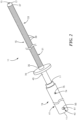
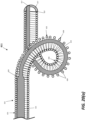
- Figs. 1 through 6 there are shown various views of a first embodiment of a snare device, the snare device being constructed according to the teachings of the present invention and being represented generally by reference numeral 11. Details of snare device 11 that are discussed elsewhere in this application or that are not critical to an understanding of the invention may be omitted from one or more of Figs. 1 through 6 and/or from the accompanying description herein or may be shown in one or more of Figs. 1 through 6 and/or described herein in a simplified manner.
- Snare device 11 may comprise a core-wire 13, a support 15, an end cap 17, and an actuator 19.
- Core-wire 13 which is also shown separately in Figs. 7 and 8 , may be an elongated, flexible, inhomogeneous filamentary structure that is capable of transitioning from a relaxed state to a tensioned state when subjected to a threshold tensile or pulling force.
- core-wire 13 may comprise a proximal portion 21 and a distal portion 23.
- Proximal portion 21 may terminate proximally at a proximal end 25 of core-wire 13
- distal portion 23 may terminate distally at a distal end 27 of core-wire 13.
- Proximal portion 21 and distal portion 23 may be contiguous with one another or may be interconnected by a short intermediate portion 29.
- proximal portion 21 may be characterized by having a first strain in response to a given tensile force (which first strain may be uniform along the entire length of proximal portion 21), and distal portion 23 may be characterized by having a second strain in response to the same tensile force (which second strain may be uniform along the entire length of distal portion 23), wherein the first strain of proximal portion 21 is less than the second strain of distal portion 23.
- the first strain of proximal portion 21 may be in the initial elastic region (i.e., completely reversible length, no permanent elongation) whereas the second strain of distal portion 23 may be in the superelastic region (i.e., some permanent elongation).
- Proximal portion 21 of core-wire 13 may have a relaxed state in which it is substantially straight in overall shape, and distal portion 23 of core-wire 13 may have a relaxed state in which it includes a looped or coiled shape.
- the looped or coiled shape of distal portion 23, in the relaxed state may be a generally circular shape.
- the looped or coiled shape of distal portion 23 may comprise a conical helix, a cylindrical helix, other rounded shapes, or combinations thereof.
- distal portion 23 When core-wire 13 is pulled to its tensioned state, distal portion 23 may lengthen, and its looped or coiled shape may substantially straighten. (To the extent that proximal portion 21 may also lengthen, such lengthening may be minor or negligible as compared to that experienced by distal portion 23.)
- core-wire 13 may be a unitary or one-piece structure made of a super-elastic and shaped-memory material. Such a material has the property that, when deformed and heated past a critical temperature, it "remembers" its deformed state. When cooled and subjected to further deformation, such a material springs back to this remembered shape.
- a suitable super-elastic material from which core-wire 13 may be manufactured is a nickel-titanium alloy commonly sold under the trade name NITINOL TM . In the case of the aforementioned nickel-titanium alloy, the critical temperature is in the neighborhood of 371-548.9 degrees Celsius (700-1020 degrees Fahrenheit).
- core-wire 13 is a unitary structure made of a super-elastic, memory-shaped material
- the difference in yield forces between proximal portion 21 and distal portion 23 may be achieved by providing proximal portion 21 with a first filamentary cross-sectional diameter di, which may be substantially uniform along the entire length of proximal portion 21, and by providing distal portion 23 with a second filamentary cross-sectional diameter d 2 , which may be substantially uniform along the entire length of distal portion 23, wherein second filamentary cross-sectional diameter d 2 is smaller than first filamentary cross-sectional diameter d 1 .
- Intermediate portion 29 may uniformly taper in filamentary cross-sectional diameter from proximal portion 21 to distal portion 23.
- proximal portion 21 of core-wire 13 has a greater filamentary cross-sectional diameter than does distal portion 23 of core-wire 13
- a given tensioning force applied to core-wire 13 results in more stress being applied to distal portion 23 of core-wire 13 than to proximal portion 21 of core-wire 13.
- distal portion 23 experiences more strain, and hence greater elongation, than does proximal portion 21.
- both proximal portion 21 of core-wire 13 and distal portion 23 of core-wire 13 may be generally circular in filamentary cross-sectional shape; however, it is to be understood that proximal portion 21 of core-wire 13 and distal portion 23 of core-wire 13 need not be circular in filamentary cross-sectional shape and may possess other filamentary cross-sectional shapes.
- core-wire 13 is a unitary wire made of a single material
- different lengths of core-wire 13 may have different filamentary cross-sectional diameters.
- proximal portion 21 and distal portion 23 may have different filamentary cross-sectional diameters from one another.
- the ratio of the filamentary cross-sectional diameters of proximal portion 21 and distal portion 23 of core-wire 13 may depend on the material properties of core-wire 13. The ratio may be selected such that a suitable differential strain can be achieved with only a modest exertion of force by an operator.
- the respective filamentary cross-sectional diameters of proximal portion 21 and distal portion 23 of core-wire 13 may be such that the tensile force applied by an operator will be insufficient for core-wire 13 to lose the memory of its remembered shape. In general, this means that the tensile force must be such that the distal portion 23 is elongated by less than 8% of its relaxed length, and preferably within 2% to 7% of its relaxed length.
- a continuous wire made of a shaped-memory metal is ground to a smaller filamentary diameter to form the distal portion 23.
- the distal portion 23 is then heat-set to the desired shape.
- This may be achieved by ensuring that the ratio of the filamentary diameter of the proximal portion 21 to that of the distal portion 23 is about 1.35 or greater.
- this may be achieved by ensuring that the ratio of the area of the proximal portion 21 to that of the distal portion 23 is about 1.8 or greater.
- the actual transition from one state to another can be viewed as a wave traveling along core-wire 13.
- the direction in which this wave travels can be controlled by controlling the taper of the transition between proximal portion 21 and distal portion 23.
- the wave travels from proximal portion 21 to distal portion 23 when the operator tensions on core-wire 13.
- the wave again travels from proximal portion 21 to distal portion 23.
- core-wire 13 may be formed from a unitary length of material by a local heat-treatment to change the yield stress in the heat-treated region. This may be done, for example, by applying heat locally to the distal portion while masking the heat from the proximal portion. In some cases, the application of localized heat to form the distal section may eliminate a need to grind core-wire 13. In other cases, the application of localized heat may reduce the ratio of the proximal portion filamentary diameter to the distal portion filamentary diameter.
- core-wire 13 may be a unitary structure, other methods exist of providing core-wire 13 with portions with different yield strengths. For example, core-wire 13 may be made by joining together two dissimilar materials having different yield strengths.
- core-wire 13 may be formed by joining together a proximal portion 21 made of stainless steel, MP35N ® nickel-chromium-cobalt alloy (SPS Technologies LLC, Jenkintown, PA), or the like and a distal portion 23 made of NITINOL TM nickel-titanium alloy or the like.
- proximal and distal portions may be joined together by one or more of welding (e.g., butt, seam, lap, resistance, friction), soldering, brazing, or one or more adhesives.
- core-wire 13 is described above as consisting of or comprising a super-elastic material, it is to be understood that core-wire 13 need not include a super-elastic material.
- core-wire 13 may consist of or comprise a non-super-elastic material, such as a high tensile stainless steel, where distal portion 23 of core-wire 13 is significantly smaller in filamentary cross-sectional diameter than proximal portion 21 of core-wire 13 (e.g., filamentary cross-sectional diameter ratio of proximal portion 21 to distal portion 23 is greater than 3:1) and the strain/elongation of distal portion 23 does not exceed the yield point.
- core-wire 13 may be coated with a lubricious coating to reduce friction between core-wire 13 and support 15.
- a composition or material that may be used to form the lubricious coating may be polytetrafluoroethylene (PTFE).
- the lubricious coating may be applied along the entire length of core-wire 13 or may be applied only to a portion thereof, for example, only to proximal portion 21.
- core-wire 13 may be coated with other types of materials, such as a hydrophilic and biocompatible composite material, examples of which include polyvinyl pyrrolidone (PVP), polyacrylamide, and hyaluronic acid.
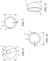
- Support 15 which is also shown separately in Figs. 9 and 10 , may be an elongated tubular structure of generally circular overall cross-section comprising a proximal portion 31 and a distal portion 33.
- support 15 may be in the form of a flexible coiled wire or filament.
- the coiled wire or filament of support 15 preferably has a round filamentary cross-sectional shape, such as a circular filamentary cross-sectional shape.
- a round filamentary cross-sectional shape is desirable as the edges of the round wire coil tend to line up more consistently when compressed, providing greater column strength when placed under compression.
- support 15 may be inserted over core-wire 13 so that proximal portion 31 may be generally disposed over much of proximal portion 21 of core-wire 13 and so that distal portion 33 may be generally disposed over much of distal portion 23 of core-wire 13.
- Proximal portion 31 may terminate proximally at a proximal end 35 of support 15, and distal portion 33 may terminate distally at a distal end 37 of support 15.
- proximal portion 31 and distal portion 33 may be contiguous with one another, and support 15 may be a unitary or one-piece structure. (Alternatively, as disclosed, for example, in U.S. Patent Nos.
- support 15 may be a multi-piece structure wherein proximal portion 31 is a cannula and distal portion 33 is a coiled wire.)
- support 15 may have a uniform filamentary cross-sectional diameter d 3 along its entire length, may have a uniform overall cross-sectional diameter d 4 along its entire length, and may possess a uniform tensile strength along its entire length.
- support 15 may be a coiled wire and may comprise a segmented structure capable of articulation between its constituent segments or turns 39.
- support 15 has an equilibrium compressed state, in which it defines a straight path corresponding to that shown in Fig. 2 , and a non-equilibrium uncompressed state, in which proximal portion 31 follows a generally straight path and distal portion 33 follows a coiled path corresponding to that shown in Fig. 1 .
- all or substantially all of turns 39 may be in contact with their neighboring turns 39.
- turns 39 of distal portion 33 may be in contact with their neighboring turns 39 along an inner radius 36 but may be separated from one another along an outer radius 38 (as seen, for example, in Fig. 5 ).
- outer radius 38 may be comparatively shorter in length (and may be equal in length to inner radius 36) whereas, when support 15 is uncompressed, outer radius 38 maybe comparatively longer in length (and may be longer in length than inner radius 36).
- Support 15 may consist of or comprise a strong coilable material, such as a stainless steel, a titanium alloy, a chromium-cobalt alloy (e.g., MP35N ® cobalt alloy, L-605 cobalt-chromium-tungsten-nickel alloy, etc.), or any other suitable strong coilable metal or other material.
- Support 15 may be made of one or more materials that are safe for use during magnetic resonance procedures.
- Support 15 may be coated with a hydrophilic and biocompatible composite material, such as polyvinyl pyrrolidone (PVP), polyacrylamide or hyaluronic acid.
- a suitable outer overall diameter of support 15 for general intra-vascular use may be approximately 0.036 cm (0.014 inches).
- support 15 may be made of, or may include a portion made of, a radiopaque material such as platinum, tungsten, iridium, tin, gold, silver, or an alloy thereof.
- support 15 may be made of a coilable material coated with a radiopaque coating.
- Support 15 may comprise a close wound coil, with or without preload, or it may comprise an open wound coil.
- support 15 may further comprise a sleeve (or other type of cover) disposed around the outside of proximal portion 31 and/or a sleeve (or other type of cover) disposed around the outside of distal portion 33.
- sleeves may be, for example, a unitary structure covering both proximal portion 31 and distal portion 33.
- a sleeve covering proximal portion 31 may be made of one or more materials possessing good lubricity, such as polytetrafluoroethylene (PTFE), or may be made of one or more materials, such as polyethylene terephthalate (PET) or urethane, to which a lubricious coating is applied.
- PTFE polytetrafluoroethylene
- PET polyethylene terephthalate
- urethane to which a lubricious coating is applied.
- the sleeve may be coated with a hydrophilic and biocompatible composite material of the type discussed above in connection with core-wire 13 and support 15.
- the sleeve may have properties conducive to protecting the coiled wire of support 15 from laser radiation (e.g., laser radiation from a YAG laser), which may be desirable where snare device 11 may be used in procedures involving the use of such lasers (e.g., stone lithotripsy).
- a sleeve covering distal portion 33 may comprise materials having both highly elastic properties and low durometer, such as silicone or urethane, and/or may comprise materials having good lubricious properties, such as PTFE.
- Such a sleeve may serve to fill spaces between adjacent turns 39 of distal portion 33 of support 15 when snare device 11 is in its coiled state. By filling such spaces, snare device 11 may be better able to capture desired materials (e.g., stone fragments from lithotripsy, blood clots, foreign bodies) when in its coiled state.
- the sleeve which may be attached to distal portion 33 of support 15, may have an inner diameter larger than the outer overall diameter of support 15, whereby snare device 11 in its coiled state may expand within the sleeve to create a channel suitable for restoring blood flow.
- the sleeve may be of a constant size or may be highly elastic and expandable or blood permeable. This arrangement may act as a temporary stent or an embolic protection device.
- End cap 17 which is also shown separately in Fig. 11 , may be a generally hemispherically-shaped member made of a rigid material, such as stainless steel or the like. In some cases, as in the present embodiment, end cap 17 may be hollow and may include an open bottom end 40-1 and an open top end 40-2. In other cases, as shown in other embodiments below, end cap 17 may be solid. End cap 17 may be used to mechanically couple core-wire 13 and support 15 at their respective distal ends.
- distal end 27 of core-wire 13 may be fixed within top end 40-2 of end cap 17 by welding, soldering, brazing, or one or more epoxies or adhesives
- distal end 37 of support 15 may be fixed to open bottom end 40-1 of end cap 17 by welding, soldering, brazing, or one or more epoxies or adhesives.
- Actuator 19 which is also shown separately in Fig. 12 , may comprise a handle 41, an anchor 43, and a slide 45.
- Handle 41 which may be made of a rigid, durable material, such as a suitable polymer or metal, may be an elongated structure.
- handle 41 may be shaped to include a pair of longitudinally extending cavities, namely, a proximal cavity 47 and a distal cavity 49.
- Proximal cavity 47 may extend distally from a proximal end 51 of handle 41, and distal cavity 49 may extend proximally from a distal end 53 of handle 41.
- Proximal cavity 47 and distal cavity 49 may be axially aligned with one another and may be contiguous, whereby the distal end of proximal cavity 47 may open into the proximal end of distal cavity 49.
- proximal cavity 47 and distal cavity 49 may be generally cylindrical in cross-sectional shape, with proximal cavity 47 having a comparatively smaller diameter and with distal cavity 49 having a comparatively larger diameter. Proximal cavity 47 and distal cavity 49 may be appropriately dimensioned so that proximal portion 21 of core-wire 13 may be freely disposed therewithin.
- Handle 41 may be shaped further to include a cavity 55.
- Cavity 55 which may be arranged to be transverse relative to the longitudinal axis of handle 41, may extend inwardly from a side 57 of handle 41 and may intersect with and pass through proximal cavity 47.
- Anchor 43 which may be made of a rigid, durable material, such as a suitable polymer or metal, may be an elongated, barrel-shaped structure. Anchor 43 may be appropriately dimensioned to be snugly mounted, yet rotatably adjustable, within cavity 55 of handle 41.
- a transverse channel 59 may be provided in anchor 43 so that proximal end 25 of core-wire 13 may be secured to anchor 43 (for example, by being inserted through channel 59 and then tied around anchor 43).
- a slot 61 may be provided in an outer end of anchor 43 and may be shaped to receive a flat-head screwdriver or similarly shaped tool (not shown) that may be used to rotate anchor 43 within cavity 55. As can be appreciated, by rotating anchor 43 within cavity 55, the amount of tension that is applied to core-wire 13 may be adjusted.
- Slide 45 which may be made of a rigid, durable material, such as a suitable polymer or metal, may be an elongated, hollow structure. Slide 45 may be appropriately dimensioned to be slidably mounted within distal cavity 49 of handle 41 so as to move proximally and distally therewithin. Slide 45 may be shaped to include a proximal end 65, a distal end 67, and a longitudinal cavity 69 that may extend from proximal end 65 to distal end 67. Cavity 69 may be appropriately dimensioned to permit core-wire 13 to extend freely therethrough. Proximal end 35 of support 15 may be fixedly secured to distal end 67 of slide 45 by welding, soldering, brazing, adhesive or other suitable means.
- a grip 70 may be fixedly mounted on slide 45 for use in moving slide 45 back and forth within handle 41.
- a stop 71 may be mounted in an opening 72 on slide 45 and may be movable within a track 73 formed in handle 41. Stop 71 may be arranged for contact with a set screw 74 mounted in an opening 75 on handle 41 to define a range of movement of slide 45 back and forth relative to handle 41.
- proximal end 25 of core-wire 13 may be secured to anchor 43, which, in turn, may be coupled to handle 41, and distal end 27 of core-wire 13 may be secured to end cap 17.
- Proximal end 35 of support 15 may be secured to slide 45, which, in turn, may be slidably mounted on handle 41, and distal end 37 of support 15 may be secured to end cap 17.
- proximal end 35 of support 15 may be movable proximally and distally relative to proximal end 25 of core-wire 13 whereas distal end 27 of core-wire 13 may be fixed relative to distal end 37 of support 15.
- proximal end 35 of support 15 is also at its most proximal position.
- the compressive force applied to support 15 is at its relative minimum, and, consequently, a distally-directed force applied to distal end 37 of support 15 is also at its relative minimum.
- the distally-directed tensioning force applied to distal end 27 of core-wire 13 is also at its relative minimum. With the tensioning of core-wire 13 thus at its relative minimum, core-wire 13 assumes its relaxed state, with distal portion 23 of core-wire 13 forming a looped or coiled shape.
- distal portion 33 of support 15 which is constrained to follow the shape of distal portion 23 of core-wire 13, assumes a correspondingly looped or coiled shape. While in this looped or coiled shape, distal portion 33 of support 15 is uncompressed.
- proximal end 35 of support 15 is also at its most distal position.
- the compressive force applied to support 15 is at its relative maximum, and, consequently, the distally-directed force applied to distal end 37 of support 15 is also at its relative maximum.
- the distally-directed tensioning force applied to distal end 27 of core-wire 13 is also at its relative maximum. With the tensioning of core-wire 13 thus at its relative maximum, core-wire 13 stretches, particularly distal portion 23 of core-wire 13. As distal portion 23 of core-wire 13 stretches, it straightens.
- snare device 11 may be transformed from its coiled state to its straightened state by moving slide 45 from its most proximal position to its most distal position. With snare device 11 thus transformed to its straightened state, snare device 11 may then be inserted into a patient to a desired location, such as to a location where end cap 17 of snare device 11 may be positioned to a point just beyond an object to be snared. Then, snare device 11 may be transformed back to coiled state from its straightened state by moving slide 45 back to its most proximal position from its most distal position, whereby the object may be snared by the coiled or looped portion of snare device 11.
- snare device 11 may be particularly well-suited for grasping a medical instrument to guide it to a desired location.
- snare device 11 could be inserted through an implanted abdominal aortic aneurysm (AAA) endovascular aneurysm repair (EVAR) stent into the second iliac artery and adjacent to a guidewire that has been placed in the femoral artery. Deploying the circular or looped shape around the aforementioned guidewire to ensnare it, snare device 11 could then be withdrawn to guide the guidewire into the EVAR stent.
- AAA abdominal aortic aneurysm
- EVAR endovascular aneurysm repair
- Other possible uses for snare device 11 may be found in U.S. Patent Nos. 6,500,185 and 6,652,536 .
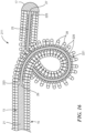
- turns 39 of support 15 may experience varying radial forces. These forces may cause one or more turns 39 to become radially displaced or "skewed" relative to core-wire 13. If the radial displacement is not too large, support 15 will not contact core-wire 13, and the tension within support 15 will restore the radially displaced turns 39 to their equilibrium aligned positions upon removal of the radial force. However, as shown in Fig. 13 , if the radial displacement is too large, as may be the case for a snare device like snare device 10 of U.S. Patent No.
- normally non-neighboring turns 85a and 85c may be caused to become adjacent to one another, permanently misaligning an intervening turn 85b. If the permanently misaligned turn 85b extends far enough inwardly to contact core-wire 87, core-wire 87 may be impaired from straightening.
- distal portion 33 of support 15 and distal portion 23 of core-wire 13 are characterized by the following relationship: Break Load distal portion 33 of support 15 > Plateau Force distal portion 23 of core-wire 13 wherein the break load of distal portion 33 of support 15 is equal to the tensile strength of distal portion 33 of support 15 multiplied by the filamentary cross-sectional area of distal portion 33 of support 15, wherein distal portion 23 of core-wire 13 has a filamentary cross-sectional area and also has an upper plateau stress in response to a tensile force applied thereto, and wherein the plateau force of distal portion 23 of core-wire 13 is equal to the upper plateau stress multiplied by the cross-sectional area of distal portion 23 of core-wire 13.
- distal portion 33 of support 15 may have a tensile strength of 2.22 ⁇ 10 9 Pa (322,000 psi) and a filamentary cross-sectional area of 6.21 ⁇ 10 -9 m 2 (9.62 x 10 -6 in 2 ), and distal portion 23 of core-wire 13 may have a filamentary cross-sectional area of 2.12 ⁇ 10 -8 m 2 (3.28 x 10 -5 in 2 ) and an upper plateau stress of 5.6 ⁇ 10 8 Pa (81,000 psi).
- the break load of distal portion 33 of support 15 is 13.8 N (3.10) (i.e., 2.22 ⁇ 10 9 Pa (322,000 psi) times 6.21 ⁇ 10 -9 m 2 (9.62 x 10 -6 in 2 )), which is greater than the plateau force of 11.9 N (2.66) (i.e., 5.6 ⁇ 10 8 Pa (81,000 psi) times 2.12 ⁇ 10 -8 m 2 (3.28 x 10 -5 in 2 )) for distal portion 23 of core-wire 13.
- the tensile strength of distal portion 33 of support 15 may be 2.07 ⁇ 10 9 -2.90 ⁇ 10 9 Pa (300,000-420,000 psi)
- the filamentary cross-sectional area of distal portion 33 of support 15 may be 3.17 ⁇ 10 -9 -6.84 ⁇ 10 -8 m 2 (4.91 ⁇ 10 -6 -1.06 ⁇ 10 -4 in 2 )
- the filamentary cross-sectional area of distal portion 23 of core-wire 13 may be 1.16 ⁇ 10 -8 -2.66 ⁇ 10 -7 m 2 (1.80 ⁇ 10 -5 -4.13 ⁇ 10 -4 in 2 )
- the upper plateau stress of distal portion 23 of core-wire 13 may be 4.8 ⁇ 10 8 -6.2 ⁇ 10 8 Pa (70,000-90,000 psi). Additional examples falling within these ranges are presented below.
- the support coil may be expected to skew.
- the distal portion of the core-wire were to have an upper plateau stress of 5.8 ⁇ 10 8 Pa (84,000 psi) and a filamentary cross-sectional area of 1.32 ⁇ 10 -8 m 2 (2.04 x 10 -5 in 2 ) and if the support coil were to consist of a platinum alloy filament having a maximum ultimate tensile strength of about 1.24 ⁇ 10 9 Pa (180,000 psi) and a filamentary cross-sectional area of 3.17 ⁇ 10 -9 m 2 (4.91 x 10 -6 in 2 ), the support coil may be expected to skew when the snare device is straightened by tensioning the core-wire and compressing the support coil.
- the plateau force of the distal portion of the core-wire would be 7.65 N (1.72 lbs), which would be greater than the break force of 3.9 N (0.88 lbs) for the support coil.
- the distal portion of the core-wire were to have an upper plateau stress of 5.8 ⁇ 10 8 Pa (84,000 psi) and a filamentary cross-sectional area of 1.32 ⁇ 10 -8 m 2 (2.04 x 10 -5 in 2 ) and if the support coil were to consist of a stainless steel wire filament having a maximum ultimate tensile strength of about 2.3 ⁇ 10 9 Pa (340,000 psi) and a filamentary cross-sectional area of 3.17 ⁇ 10 -9 m 2 (4.91 x 10 -6 in 2 ), the support coil may be expected to skew when the snare device is straightened by tensioning the core-wire and compressing the support coil. This is because the plateau force of the distal portion of the core-wire would be 7.65 N (1.72 lbs), which
- the support coil may be expected to skew. This is because the present inventor believes that a rectangular cross-sectional shape of the support coil will permit variable alignment at the support coil edges.
- the distal portion of the core-wire have a reasonably uniform filamentary diameter over its entire length in its relaxed state.
- the filamentary diameter of the distal portion of the core-wire should be reasonably uniform over its entire length.
- a typical barrel grind tolerance of ⁇ 5.1 ⁇ 10 -4 cm (0.0002 inch) is reasonable for diameters larger than 0.008 cm (0.003 inch).
- the tensile force associated with the loading plateau required to overcome the larger, more proximal diameter would result in the smaller diameter exceeding its loading plateau and elongating beyond the 8% recoverable strain.
- the smaller diameter would be plastically deformed and elongated, and the device would lose its shape in the relaxed position.
- the mechanism would not be able to transition completely from the relaxed state to the tensioned/compressed state.
- the tensile force that would be required to overcome the larger diameter would also elongate the unground core-wire, resulting in hysteresis along the entire length.
- the extended length of the core-wire would prevent the support from ever being fully compressed, and the handle stroke would be insufficient to accommodate this movement.
- NITINOL TM nickel-titanium alloy has a largely recoverable engineering strain, e, of 6-8%.
- the device will tend to skew in these locations since the compression force to overcome the tensioned wire shape will be focused at these points. Skewing from sharp bends may be mitigated against by increasing the ratio of coil wire break load vs core-wire plateau force.
- proximal portion 21 is circular in cross-sectional shape and has a uniform filamentary cross-sectional diameter of 0.03 cm (0.012 in)
- distal portion 23 is circular in cross-sectional shape and has a uniform filamentary cross-sectional diameter of 0.020 cm (0.0079 in).
- distal portion 23 exhibits an upper plateau stress (i.e., an upper region of approximately constant stress in the stress-strain curve) of approximately 5.7 ⁇ 10 8 -5.8 ⁇ 10 8 Pa (82,000-84,000 psi).
- snare device 111 there is shown an enlarged fragmentary section view of a second embodiment of a snare device constructed according to the teachings of the present invention, the snare device being represented generally by reference numeral 111. Details of snare device 111 that are discussed elsewhere in this application or that are not critical to an understanding of the invention may be omitted from Fig. 15 and/or from the accompanying description herein or may be shown in Fig. 15 and/or described herein in a simplified manner.
- Snare device 111 may be similar in most respects to snare device 11.
- One difference between snare device 111 and snare device 11 may be that, whereas snare device 11 may comprise a core-wire 13 whose distal end 27 is anchored to end cap 17, snare device 111 may comprise a core-wire 113 whose distal end 127 is not anchored to end cap 17. Instead, distal end 127 of core-wire 113 may be anchored to an anchoring element 131 disposed on distal portion 33 of support 15 at an intermediate point that is distal to the coiled or looped shape of core-wire 113 and is proximal to distal end 37 of support 15.
- a safety wire 133 may extend distally from anchoring element 131 to end cap 17 to prevent the support 15 from unravelling. This arrangement isolates any tensile force applied to core-wire 113 to points proximal to the aforementioned intermediate point and results in a coiled or looped shape having a floppy and atraumatic distal tip. Such an atraumatic tip may be advantageous because it enables the instrument to be maneuvered in constricted regions without a significant risk of perforating or otherwise damaging surrounding structures.
- snare device 211 there is shown an enlarged fragmentary section view of a third embodiment of a snare device constructed according to the teachings of the present invention, the snare device being represented generally by reference numeral 211. Details of snare device 211 that are discussed elsewhere in this application or that are not critical to an understanding of the invention may be omitted from Fig. 16 and/or from the accompanying description herein or may be shown in Fig. 16 and/or described herein in a simplified manner.
- Snare device 211 may be similar in most respects to snare device 11.
- One difference between snare device 211 and snare device 11 may be that snare device 211 may further comprise a spacer coil 221.
- Spacer coil 221 may have a proximal end attached to a proximal spacer 223 mounted on intermediate portion 29 of core-wire 13 and may have a distal end attached to a distal spacer 225 mounted on core-wire 13 proximate to distal end 27.
- Spacer coil 221 may comprise or consist of a radiopaque material, such as platinum. However, other materials may also be used depending on the specific application of the instrument 211.
- Other tubular structures may be used in place of spacer coil 221 to enclose core-wire 13. For example, baffles, bellows or any such flexible and compressible tube having dimensions as described below can also be used.
- Spacer coil 221 may consist of a single wire formed into a coil or may comprise two or more wires
- Spacer coil 221 may be in contact with core-wire 13 or may be separated therefrom by a clearance that is small enough to minimize the likelihood that articulating spacer-coil segments or turns 229 of spacer coil 221 may, themselves, become radially displaced relative to core-wire 13.
- This clearance is preferably determined by the dimensions of spacer coil 221. In one embodiment, the clearance is selected to be less than the radius of the windings or turns that make up spacer coil 221.
- spacer coil 221 and support 15 may be dimensioned relative to one another to minimize the skewing of support 15 and, additionally, to minimize the likelihood that spacer coil 221 and support 15 may bind with each other during use.
- the pitch angle of turns 229 of spacer coil 221 is preferably selected to be different from the pitch angle of turns 39 of support 15. Such a difference can be achieved by winding spacer coil 221 and support 15 in opposite directions. In one embodiment, these two pitch angles are at right angles to each other. However, any difference in pitch angle will reduce the likelihood of penetration.
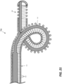
- Fig. 17 there is shown an enlarged fragmentary section view of a fourth embodiment of a snare device constructed according to the teachings of the present invention, the snare device being represented generally by reference numeral 311. Details of snare device 311 that are discussed elsewhere in this application or that are not critical to an understanding of the invention may be omitted from Fig. 17 and/or from the accompanying description herein or may be shown in Fig. 17 and/or described herein in a simplified manner.
- Snare device 311 may be similar in most respects to snare device 11.
- snare device 311 may comprise a core-wire 313, instead of core-wire 13.
- Core-wire 313 may differ from core-wire 13 in that core-wire 313 may comprise a distal portion 323 that may include a conical helix (i.e., larger turns proximally and tapering smaller turns distally) when in its relaxed state.
- a conical helix may be used like a basket and may be useful for such purposes as capturing kidney stone fragments during lithotripsy (retropulsion).
- a blood permeable sack or sock (such as in U.S. Patent Application Publication No. 2009/0209987 A1 ) may be attached to the distal region 35 of support 15 to enable device 311 to be used as an embolic protection device.
- Fig. 18 there is shown an enlarged fragmentary section view of a fifth embodiment of a snare device constructed according to the teachings of the present invention, the snare device being represented generally by reference numeral 411. Details of snare device 411 that are discussed elsewhere in this application or that are not critical to an understanding of the invention may be omitted from Fig. 18 and/or from the accompanying description herein or may be shown in Fig. 18 and/or described herein in a simplified manner.
- Snare device 411 may be similar in most respects to snare device 11.
- One difference between snare device 411 and snare device 11 may be that snare device 411 may comprise a core-wire 413, instead of core-wire 13.
- Core-wire 413 may differ from core-wire 13 in that core-wire 413 may comprise a distal portion 423 that may include a cylindrical helix when in its relaxed state.
- Such a cylindrical helix may be useful for such purposes as forming a temporary stent to open an otherwise occluded or constricted lumen in a person's body.
- snare device 411 could be used to open blood vessels to restore blood flow, to open gastrointestinal vessels to allow the flow of food, bile, etc., and to open a ureter to restore the flow of urine.
- Fig. 19 there is shown an enlarged fragmentary section view of a sixth embodiment of a snare device constructed according to the teachings of the present invention, the snare device being represented generally by reference numeral 511. Details of snare device 511 that are discussed elsewhere in this application or that are not critical to an understanding of the invention may be omitted from Fig. 19 and/or from the accompanying description herein or may be shown in Fig. 19 and/or described herein in a simplified manner.
- Snare device 511 may be similar in most respects to snare device 11.
- One difference between snare device 511 and snare device 11 may be that snare device 511 may comprise a core-wire 513, instead of core-wire 13.
- Core-wire 513 may differ from core-wire 13 in that core-wire 513 may comprise a distal portion 523 that may include, when in its relaxed state, a combination of a proximal cylindrical helix 525 and a distal cone 527.
- Such a shape may be useful as a snare to capture objects, such as blood clots, gallstones, and other foreign bodies.
- the present inventor offers the following: When the device is in its straightened configuration, the coils of the support are usually compressed, thus defining the path. However, as the device is relaxed, the coils of the support are no longer actively compressed, and the core-wire is no longer placed in tension. As a result, the non-straight configuration of the core-wire should then define the shape of the device. During this transition, the motion of return typically begins at the proximal end of the device and propagates towards the distal end.
- the distal portion of the looped or non-straight configuration does not fully return to the original, relaxed state but remains somewhere between the straight configuration and the looped configuration, where the compressed coil still provides some definition to the shape. Typically, this is primarily due to frictional forces between the coils of the support and the core-wire.
- FIGs. 20(a) and 20(b) show another embodiment of a snare device constructed according to the present invention, the snare device being represented by reference numeral 611.
- snare devices 611 and 11 may be similar in many respects.
- snare device 11 may be regarded as an idealized embodiment of a snare device of the present invention (which idealized embodiment may be attained or approximated in some cases) whereas snare device 611 may be regarded as an alternative or variant embodiment of such a snare device that may be found in practice (which alternative embodiment may be attained or approximated in some cases). Accordingly, parts of snare device 611 that correspond to parts of snare device 11 are identified by reference numbers that exceed those of snare device 11 by 600.
- a principal difference between snare devices 11 and 611 is that, in snare device 11, distal portion 23 of core-wire 13 is shown as not contacting any part of distal portion 33 of support 15. By contrast, in snare device 611, distal portion 623 of core-wire 613 is shown as contacting at least some turns 639 of support 615. Such contact between distal portion 623 and support 615 while snare device 611 is in a straightened configuration (as in Fig. 20(b) ) may cause distal portion 623 to frictionally engage or bind to support 615 and, in so doing, may impede or prevent snare device 611 from transitioning completely from a straightened configuration to a looped configuration.
- distal end 627 of core-wire 613 is not shown in Figs. 20(a) and 20(b) as centered within end cap 617, distal end 627 may be centered within end cap 617.
- the present inventor has identified certain modifications to the snare device that may be made.
- One such modification is to place a slight stretch in the support just proximal to the joint between the core-wire and the support. What this modification may accomplish is to provide a spring force to the compressed coils of the support so that, when the core-wire tension is released, the spring force is also released. Consequently, as the coils of the support reopen, they tend to slide along the core-wire and overcome the frictional forces holding the snare device in a semi-straight orientation.
- the gap stretch is no greater than approximately one coil width, and one-half of a coil width is often sufficient to overcome the aforementioned frictional forces. In most cases, the length of the stretch only needs to be up to 4 times the coil diameter to overcome the frictional forces. This distal coil stretch may aid in the device returning to its fully relaxed configuration.
- Another modification is to choose opposing wind directions for the core-wire loop and the coils of the support.
- a form tool is generally used to hold the core-wire in place before it is placed into a heat zone.
- This helix has a wind direction, as do the coils of the support.
- the core-wire is placed inside a coiled support, if the wind direction of the coiled support and the core-wire are the same, the angles are somewhat similar, and the device may resist returning to a looped configuration when at rest.
- the wind directions of the core-wire and the coiled support are opposite (e.g. left vs. right), the angles are more different, and the two members may slip more easily in relation to each other, thereby allowing the looped configuration to return more completely.
- Fig. 21 there is shown an enlarged fragmentary section view of an eighth embodiment of a snare device constructed according to the teachings of the present invention, the snare device being represented generally by reference numeral 711. Details of snare device 711 that are discussed elsewhere in this application or that are not critical to an understanding of the invention may be omitted from Fig. 21 and/or from the accompanying description herein or may be shown in Fig. 21 and/or described herein in a simplified manner.
- snare device 711 may include both of the modifications discussed above for promoting a more complete transitioning from a straightened configuration to a looped configuration. More specifically, snare device 711 may comprise a core-wire 713 and a support 715. Core-wire 713 may be identical to core-wire 13. Support 715 may be similar in many respects to support 15 but may differ from support 15 in the following two respects: First, whereas support 15 may comprise a coiled wire having a right-handed wind direction (see Fig. 5 , where turns 39 are angled from right to left moving downwardly), support 715 may comprise a coiled wire having a left-handed wind direction (i.e., turns 739 are angled from left to right moving downwardly).
- turns 39 of support 15 are closely packed or compressed in the area proximal to the distal joinder of core-wire 13 and support 15 (even when snare device 11 is in its looped configuration)
- turns 739 of support 715 are spaced apart in an area 740 proximal to the distal joinder of core-wire 713 and support 715. (It may be noted that, although the distal end of core-wire 713 is not shown in Fig. 21 as centered within the end cap, the distal end of core-wire 713 may be centered within the end cap.)
- snare device 711 is shown as differing from snare device 11 in both of the respects discussed above, snare device 711 may differ from snare device 11 in only one or the other of these two respects. Moreover, the problems discussed above and the modifications thereto may apply to any of the snare devices of the present invention.
- a snare device like that of Figs. 1-6 of the present application was constructed.
- the core-wire of the snare device was made of NITINOL TM nickel-titanium alloy, with the proximal portion of the core-wire being circular in cross-sectional shape and having a uniform filamentary cross-sectional diameter of 0.019 cm (0.0075 in) and with the distal portion of the core-wire being circular in cross-sectional shape and having a uniform filamentary cross-sectional diameter of 0.013 cm (0.0051 in). Consequently, the filamentary cross-sectional area of the distal portion of the core-wire was 1.32 ⁇ 10 -8 m 2 (2.04 x 10 -5 in 2 ).
- the upper plateau stress for the distal portion of the core-wire was 5.8 ⁇ 10 8 Pa (84,000 psi). As a result, the plateau force for the distal portion of the core-wire was 7.65 N (1.72 lbs).
- the support of the subject snare device was in the form of a coil made of a stainless steel wire of round cross-section having the highest tensile strength that is commercially available, i.e., 2.9 ⁇ 10 9 Pa (420,000 psi) (Fort Wayne Metals, Fort Wayne, Indiana).
- the support had a uniform overall outer diameter of 0.0343 cm (0.0135 in) and a uniform overall inner diameter of 0.022 cm (0.0085 in). Consequently, the filamentary cross-sectional diameter of the support was 0.0064 cm (0.0025 in), and the filamentary cross-sectional area of the support was 3.17 ⁇ 10 -9 m 2 (4.91 x 10 -6 in 2 ).
- the support coil column strength was found to be sufficient to resist skewing when compressed by the tensile force applied by the core-wire.
- the core-wire of the snare device was made of NITINOL TM nickel-titanium alloy, with the proximal portion of the core-wire having a uniform filamentary cross-sectional diameter of 0.0307 cm (0.0121 in) and with the distal portion of the core-wire having a uniform filamentary cross-sectional diameter of 0.021 cm (0.0082 in). Consequently, the filamentary cross-sectional area of the distal portion of the core-wire was 3.41 ⁇ 10 -8 m 2 (5.28 ⁇ 10 -5 in 2 ) The upper plateau stress for the distal portion of the core-wire was 5.9 ⁇ 10 8 Pa (85,000 psi). As a result, the plateau force for the distal portion of the core-wire was 20 N (4.5 lbs).
- the support of the subject snare device was in the form of a coil made of a stainless steel wire of round cross-section having an ultimate tensile strength of 2.3 ⁇ 10 9 Pa (340,000 psi).
- the support had a uniform overall outer diameter of 0.0574 cm (0.0226 in) and a uniform overall inner diameter of 0.0345 cm (0.0136 in). Consequently, the filamentary cross-sectional diameter of the support was 0.011 cm (0.0045 in), and the filamentary cross-sectional area of the support was 1.03 ⁇ 10 -8 m 2 (1.59 x 10 -5 in 2 ).
- the ultimate tensile strength of the support was 2.3 ⁇ 10 9 Pa (340,000 psi).
- the support coil column strength was found to be sufficient to resist skewing when compressed by the tensile force applied by the core-wire.
- the core-wire of the snare device was made of NITINOL TM nickel-titanium alloy, with the proximal portion of the core-wire having a uniform filamentary cross-sectional diameter of 0.0376 cm (0.0148 in) and with the distal portion of the core-wire having a uniform filamentary cross-sectional diameter of 0.025 cm (0.0098 in). Consequently, the filamentary cross-sectional area of the distal portion of the core-wire was 4.86 ⁇ 10 -8 m 2 (7.54 x 10 -5 in 2 ).
- the upper plateau stress for the distal portion of the core-wire was 5.36 ⁇ 10 8 Pa (77,700 psi). As a result, the plateau force for the distal portion of the core-wire was 26 N (5.9 lbs).
- the support of the subject snare device was in the form of a coil made of a stainless steel wire of round cross-section having an ultimate tensile strength of 2.37 ⁇ 10 9 Pa (344,000 psi).
- the support had a uniform overall outer diameter of 0.0668 cm (0.0263 in) and a uniform overall inner diameter of 0.0414 cm (0.0163 in). Consequently, the filamentary cross-sectional diameter of the support was 0.013 cm (0.0050 in), and the filamentary cross-sectional area of the support was 1.26 ⁇ 10 -8 m 2 (1.96 x 10 -5 in 2 ).
- the ultimate tensile strength of the support was 2.37 ⁇ 10 9 Pa (344,000 psi).
- the support coil column strength was found to be sufficient to resist skewing when compressed by the tensile force applied by the core-wire.
- the core-wire of the snare device was made of NITINOL TM nickel-titanium alloy, with the proximal portion of the core-wire having a uniform filamentary cross-sectional diameter of 0.0307 cm (0.0121 in) and with the distal portion of the core-wire having a uniform filamentary cross-sectional diameter of 0.023 cm (0.0090 in). Consequently, the filamentary cross-sectional area of the distal portion of the core-wire was 4.10 ⁇ 10 -8 m 2 (6.36 x 10 -5 in 2 ).
- the upper plateau stress for the distal portion of the core-wire was 5.9 ⁇ 10 8 Pa (85,000 psi). As a result, the plateau force for the distal portion of the core-wire was 24 N (5.4 lbs).
- the support of the subject snare device was in the form of a coil made of a stainless steel wire of round cross-section having an ultimate tensile strength of 2.3 ⁇ 10 9 Pa (340,000 psi).
- the support had a uniform overall outer diameter of 0.0574 cm (0.0226 in) and a uniform overall inner diameter of 0.0345 cm (0.0136 in). Consequently, the filamentary cross-sectional diameter of the support was 0.011 cm (0.0045 in), and the filamentary cross-sectional area of the support was 1.03 ⁇ 10 -8 m 2 (1.59 x 10 -5 in 2 ).
- the ultimate tensile strength of the support was 2.3 ⁇ 10 9 Pa (340,000 psi).
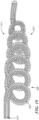
- Fig. 22 is a photo showing the skewed support of this device.
Landscapes
- Health & Medical Sciences (AREA)
- Surgery (AREA)
- Life Sciences & Earth Sciences (AREA)
- Heart & Thoracic Surgery (AREA)
- Nuclear Medicine, Radiotherapy & Molecular Imaging (AREA)
- Vascular Medicine (AREA)
- Engineering & Computer Science (AREA)
- Biomedical Technology (AREA)
- Orthopedic Medicine & Surgery (AREA)
- Medical Informatics (AREA)
- Molecular Biology (AREA)
- Animal Behavior & Ethology (AREA)
- General Health & Medical Sciences (AREA)
- Public Health (AREA)
- Veterinary Medicine (AREA)
- Surgical Instruments (AREA)
Claims (15)
- Un instrument (11, 111, 211, 311, 411, 511, 611, 711) comprenant :un support (15) s'étendant longitudinalement, définissant un axe, le support (15) ayant un état non comprimé de longueur comparativement plus grande et un état comprimé de longueur comparativement plus petite, le support (15) comprenant une section distale flexible (33), la section distale flexible (33) comprenant un filament enroulé de forme transversale ronde et définissant un premier trajet par rapport à l'axe lorsqu'elle est dans l'état comprimé, la section distale flexible (33) ayant une résistance à la traction, une surface de section transversale filamentaire et une charge de rupture, la charge de rupture de la section distale flexible (33) étant égale à la résistance à la traction de la section distale flexible (33) multipliée par la surface filamentaire en section transversale de la section distale flexible (33) ;un fil central (13), s'étendant le long de l'axe et ancré à la section distale flexible (33) du support (15), le fil central (13) ayant un état relâché de longueur comparativement plus petite et un état tendu de longueur comparativement plus grande, le fil central (13) comprenant une partie proximale (21) se terminant à une extrémité proximale (25) du fil central (13) et une partie distale (23) se terminant à une extrémité distale (27) du fil central (13), la partie distale (23) du fil central (13) définissant un deuxième trajet par rapport à l'axe lorsqu'il est dans l'état relâché, le deuxième trajet étant différent du premier trajet et comprenant une forme en boucle,la partie distale (23) du fil central (13) ayant un diamètre filamentaire (d2) et une surface filamentaire en section transversale, la partie distale (23) du fil central (13) ayant également une contrainte de plateau supérieure en réponse à une force de traction appliquée à elle, une force de plateau de la partie distale (23) du fil central (13) étant égale à la contrainte de plateau supérieure multipliée par la surface filamentaire en section transversale de la partie distale (23) du fil central (13), la partie distale (23) du fil central (13) ayant une longueur, et le diamètre filamentaire (d2) de la partie distale (23) du fil central (13) étant sensiblement uniforme sur la longueur de la partie distale (23) du fil central (13) dans l'état détendu ; etun actionneur (19), fixé à une extrémité proximale (25) du fil central (13) et à une extrémité proximale (35) du support (15) pour appliquer sélectivement à la fois une force de traction au fil central (13) et une force de compression au support (15), la force de traction provoquant la transition du fil central (13) de son état relâché à son état tendu, la force de compression provoquant la transition du support (15) de son état non comprimé à son état comprimé ;caractérisé en ce que la charge de rupture de la section distale flexible (33) du support (15) est supérieure à la force de plateau de la partie distale (23) du fil central (13).
- L'instrument (11, 111, 211, 311, 411, 511, 611, 711) tel que revendiqué dans la revendication 1, dans lequel le support (15) se termine distalement à une extrémité distale (37), et dans lequel l'extrémité distale (27) du fil central (13) est ancrée à l'extrémité distale (37) du support (15) ou dans lequel l'extrémité distale (27) du fil central (13) est ancrée au support (15) à une distance proximale de l'extrémité distale (37) du support (15).
- L'instrument (11, 111, 211, 311, 411, 511, 611, 711) tel que revendiqué dans la revendication 1, dans lequel la forme en boucle est généralement circulaire ou dans lequel la forme en boucle comprend une hélice conique ou dans lequel la forme en boucle comprend une hélice cylindrique ou dans lequel la forme en boucle comprend une hélice cylindrique proximale et une hélice conique distale.
- L'instrument (11, 111, 211, 311, 411, 511, 611, 711) tel que revendiqué dans la revendication 1, dans lequel la partie proximale (21) du fil central (13) présente une première tension en réponse à une force de traction, la partie distale (23) du fil central (13) présente une deuxième tension en réponse à la force de traction, et la première tension étant inférieure à la deuxième tension.
- L'instrument (11, 111, 211, 311, 411, 511, 611, 711) tel que revendiqué dans la revendication 4, dans lequel le fil central (13) comprend un matériau superélastique, la première tension étant présente dans une zone élastique initiale et la deuxième tension étant présente dans une zone superélastique.
- L'instrument (11, 111, 211, 311, 411, 511, 611, 711) tel que revendiqué dans la revendication 5, dans lequel le fil central (13) est une structure en une pièce comprenant un alliage nickel-titane, la partie proximale (21) du fil central (13) ayant un diamètre filamentaire (di) de dimension comparativement plus grande et la partie distale (23) du fil central (13) ayant un diamètre filamentaire (d2) de dimension comparativement plus petite.
- L'instrument (11, 111, 211, 311, 411, 511, 611, 711) tel que revendiqué dans la revendication 1, dans lequel au moins une partie du fil central (13) est revêtue d'un revêtement lubrifiant.
- L'instrument (11, 111, 211, 311, 411, 511, 611, 711) tel que revendiqué dans la revendication 1, dans lequel le premier trajet est une ligne droite.
- L'instrument (11, 111, 211, 311, 411, 511, 611, 711) tel que revendiqué dans la revendication 1, dans lequel le support (15) comprend en outre une partie proximale (31), la partie proximale (31) du support (15) et la partie distale (33) du support (15) formant une structure en une pièce, et optionnellement dans laquelle le support (15) comprend en outre un manchon, le manchon étant disposé autour d'au moins une parmi la partie proximale (31) du support (15) et la partie distale (33) du support (15).
- L'instrument (11, 111, 211, 311, 411, 511, 611, 711) tel que revendiqué dans la revendication 1, dans lequel l'actionneur (19) comprend une poignée (41) et une glissière (45), la glissière (45) étant montée coulissante sur la poignée (41) pour être déplacée sélectivement de manière proximale et distale, l'extrémité proximale (25) du fil central (13) étant reliée à la poignée (41), l'extrémité proximale (35) du support (15) étant reliée à la glissière (45), ou dans lequel l'actionneur (19) comprend en outre un organe d'ancrage (43), l'extrémité proximale (25) du fil central (13) étant fixée à l'organe d'ancrage (43), l'organe d'ancrage (43) étant monté rotatif sur la poignée (41), de sorte que la tension appliquée au fil central (13) est ajustée par rotation de l'organe d'ancrage (43).
- L'instrument (211) tel que revendiqué dans la revendication 1, comprenant en outre une bobine d'espacement (221) montée autour de la partie distale (23) du fil central (13) et à l'intérieur par rapport au support (15).
- L'instrument (11, 111, 211, 311, 411, 511, 611, 711) tel que revendiqué dans la revendication 1, dans lequel l'actionnement de l'actionneur (19) provoque la transition du support (15) de l'état non comprimé à l'état comprimé et la transition du fil central (13) de l'état relâché à l'état tendu, et dans lequel la cessation de l'actionnement de l'actionneur (19) provoque la transition du support (15) de l'état comprimé à l'état non comprimé et la transition du fil central (13) de l'état tendu à l'état relâché.
- L'instrument (711) tel que revendiqué dans la revendication 12, dans lequel le support (715) présente une direction de vent, le fil central (713) présentant une direction de vent, la direction de vent du support (715) étant l'une parmi gauche et droite, et la direction de vent du fil central (713) étant l'autre parmi gauche et droite.
- L'instrument (711) tel que revendiqué dans la revendication 13, dans lequel, lorsque le support (715) est dans l'état non comprimé, le support (715) comprend des spires (739) qui sont espacées les unes des autres dans une zone (740) immédiatement proximale à un organe distal de jonction du fil central (713) et du support (715).
- L'instrument (711) tel que revendiqué dans la revendication 12, dans lequel, lorsque le support (715) est dans l'état non comprimé, le support (715) comprend des spires (739) qui sont espacées les unes des autres dans une zone (740) immédiatement proximale à un organe distal de jonction du fil central (713) et du support (715).
Applications Claiming Priority (2)
| Application Number | Priority Date | Filing Date | Title |
|---|---|---|---|
| US16/528,814 US11350956B2 (en) | 2019-08-01 | 2019-08-01 | Snare device with anti-skewing |
| PCT/US2020/044469 WO2021022143A1 (fr) | 2019-08-01 | 2020-07-31 | Dispositif d'anse avec anti-désalignement |
Publications (3)
| Publication Number | Publication Date |
|---|---|
| EP4007539A1 EP4007539A1 (fr) | 2022-06-08 |
| EP4007539A4 EP4007539A4 (fr) | 2023-08-23 |
| EP4007539B1 true EP4007539B1 (fr) | 2025-01-15 |
Family
ID=74230560
Family Applications (1)
| Application Number | Title | Priority Date | Filing Date |
|---|---|---|---|
| EP20846256.4A Active EP4007539B1 (fr) | 2019-08-01 | 2020-07-31 | Dispositif d'anse avec anti-désalignement |
Country Status (4)
| Country | Link |
|---|---|
| US (1) | US11350956B2 (fr) |
| EP (1) | EP4007539B1 (fr) |
| JP (1) | JP7523156B2 (fr) |
| WO (1) | WO2021022143A1 (fr) |
Families Citing this family (2)
| Publication number | Priority date | Publication date | Assignee | Title |
|---|---|---|---|---|
| US12274462B2 (en) | 2019-08-01 | 2025-04-15 | Carnelian Medical LLC | Snare device with anti-skewing |
| JP7832694B2 (ja) | 2021-03-04 | 2026-03-18 | カーネリアン メディカル エルエルシー | スネア装置 |
Family Cites Families (12)
| Publication number | Priority date | Publication date | Assignee | Title |
|---|---|---|---|---|
| WO1995001123A2 (fr) | 1993-06-24 | 1995-01-12 | Conceptus, Inc. | Dispositif de type fil de guidage et d'utilisation dudit dispositif |
| JP3274384B2 (ja) | 1997-03-31 | 2002-04-15 | 株式会社パイオラックス | 留置カテーテル及びその挿入装置 |
| JP3524788B2 (ja) | 1998-12-24 | 2004-05-10 | 株式会社パイオラックス | 制癌剤投与用体内留置カテーテル |
| US6620172B1 (en) | 1999-07-01 | 2003-09-16 | Medsource Technologies, Inc. | Entraining biological calculi |
| US6500185B1 (en) | 2000-09-29 | 2002-12-31 | Primus Medical, Inc. | Snare device |
| US7058456B2 (en) | 2002-08-09 | 2006-06-06 | Concentric Medical, Inc. | Methods and devices for changing the shape of a medical device |
| US7098292B2 (en) * | 2003-05-08 | 2006-08-29 | The Procter & Gamble Company | Molded or extruded articles comprising polyhydroxyalkanoate copolymer and an environmentally degradable thermoplastic polymer |
| US20090209987A1 (en) | 2005-02-01 | 2009-08-20 | Mathews Eric D | Snare with capture-area enhancement |
| US20060200171A1 (en) * | 2005-03-04 | 2006-09-07 | Boston Scientific Scimed, Inc. | Medical retrieval device and related methods of use |
| US20060229638A1 (en) | 2005-03-29 | 2006-10-12 | Abrams Robert M | Articulating retrieval device |
| US20130190772A1 (en) * | 2012-01-24 | 2013-07-25 | Mis Surgical, Llc | Elastic Guide Wire for Spinal Surgery |
| WO2014081942A1 (fr) | 2012-11-21 | 2014-05-30 | Concert Medical, Llc | Fil-guide préformé |
-
2019
- 2019-08-01 US US16/528,814 patent/US11350956B2/en active Active
-
2020
- 2020-07-31 JP JP2022506055A patent/JP7523156B2/ja active Active
- 2020-07-31 EP EP20846256.4A patent/EP4007539B1/fr active Active
- 2020-07-31 WO PCT/US2020/044469 patent/WO2021022143A1/fr not_active Ceased
Also Published As
| Publication number | Publication date |
|---|---|
| EP4007539A1 (fr) | 2022-06-08 |
| JP2022544062A (ja) | 2022-10-17 |
| WO2021022143A1 (fr) | 2021-02-04 |
| US20210030431A1 (en) | 2021-02-04 |
| JP7523156B2 (ja) | 2024-07-26 |
| US11350956B2 (en) | 2022-06-07 |
| EP4007539A4 (fr) | 2023-08-23 |
Similar Documents
| Publication | Publication Date | Title |
|---|---|---|
| US11197771B2 (en) | Method and apparatus for occlusion removal | |
| US7058456B2 (en) | Methods and devices for changing the shape of a medical device | |
| US6902572B2 (en) | Anchoring mechanisms for intravascular devices | |
| CN1223314C (zh) | 手术勒除装置 | |
| US8246641B2 (en) | Thrombus removal device | |
| US8353850B2 (en) | Steerable guide wire with torsionally stable tip | |
| EP0708621B1 (fr) | Dispositif medical de recuperation a deux spirales | |
| US20100082059A1 (en) | Radial coil expandable medical wire | |
| US20080275464A1 (en) | Articulating retrieval device | |
| EP4124305B1 (fr) | Cathéter super-alésage pliable | |
| EP4007539B1 (fr) | Dispositif d'anse avec anti-désalignement | |
| KR20140112424A (ko) | 자가 확장 스텐트용 원위 포획 장치 | |
| US20060106447A1 (en) | Adjustable stiffness medical system | |
| WO2008085167A1 (fr) | Fil guide orientable muni d'une extrémité stable à la torsion | |
| US12274462B2 (en) | Snare device with anti-skewing | |
| HK1056990B (en) | Surgical snare apparatus |
Legal Events
| Date | Code | Title | Description |
|---|---|---|---|
| STAA | Information on the status of an ep patent application or granted ep patent |
Free format text: STATUS: THE INTERNATIONAL PUBLICATION HAS BEEN MADE |
|
| PUAI | Public reference made under article 153(3) epc to a published international application that has entered the european phase |
Free format text: ORIGINAL CODE: 0009012 |
|
| STAA | Information on the status of an ep patent application or granted ep patent |
Free format text: STATUS: REQUEST FOR EXAMINATION WAS MADE |
|
| 17P | Request for examination filed |
Effective date: 20220228 |
|
| AK | Designated contracting states |
Kind code of ref document: A1 Designated state(s): AL AT BE BG CH CY CZ DE DK EE ES FI FR GB GR HR HU IE IS IT LI LT LU LV MC MK MT NL NO PL PT RO RS SE SI SK SM TR |
|
| DAV | Request for validation of the european patent (deleted) | ||
| DAX | Request for extension of the european patent (deleted) | ||
| REG | Reference to a national code |
Ref country code: DE Free format text: PREVIOUS MAIN CLASS: A61B0017220000 Ref country code: DE Ref legal event code: R079 Ref document number: 602020044947 Country of ref document: DE Free format text: PREVIOUS MAIN CLASS: A61B0017220000 Ipc: A61B0017221000 |
|
| A4 | Supplementary search report drawn up and despatched |
Effective date: 20230724 |
|
| RIC1 | Information provided on ipc code assigned before grant |
Ipc: A61B 17/00 20060101ALN20230718BHEP Ipc: A61B 17/22 20060101ALN20230718BHEP Ipc: A61B 17/221 20060101AFI20230718BHEP |
|
| RIC1 | Information provided on ipc code assigned before grant |
Ipc: A61B 17/00 20060101ALN20240709BHEP Ipc: A61B 17/22 20060101ALN20240709BHEP Ipc: A61B 17/221 20060101AFI20240709BHEP |
|
| GRAP | Despatch of communication of intention to grant a patent |
Free format text: ORIGINAL CODE: EPIDOSNIGR1 |
|
| STAA | Information on the status of an ep patent application or granted ep patent |
Free format text: STATUS: GRANT OF PATENT IS INTENDED |
|
| INTG | Intention to grant announced |
Effective date: 20240819 |
|
| GRAS | Grant fee paid |
Free format text: ORIGINAL CODE: EPIDOSNIGR3 |
|
| GRAA | (expected) grant |
Free format text: ORIGINAL CODE: 0009210 |
|
| STAA | Information on the status of an ep patent application or granted ep patent |
Free format text: STATUS: THE PATENT HAS BEEN GRANTED |
|
| AK | Designated contracting states |
Kind code of ref document: B1 Designated state(s): AL AT BE BG CH CY CZ DE DK EE ES FI FR GB GR HR HU IE IS IT LI LT LU LV MC MK MT NL NO PL PT RO RS SE SI SK SM TR |
|
| REG | Reference to a national code |
Ref country code: CH Ref legal event code: EP Ref country code: GB Ref legal event code: FG4D |
|
| REG | Reference to a national code |
Ref country code: DE Ref legal event code: R096 Ref document number: 602020044947 Country of ref document: DE |
|
| P01 | Opt-out of the competence of the unified patent court (upc) registered |
Free format text: CASE NUMBER: APP_68659/2024 Effective date: 20250102 |
|
| REG | Reference to a national code |
Ref country code: IE Ref legal event code: FG4D |
|
| REG | Reference to a national code |
Ref country code: NL Ref legal event code: MP Effective date: 20250115 |
|
| PG25 | Lapsed in a contracting state [announced via postgrant information from national office to epo] |
Ref country code: NL Free format text: LAPSE BECAUSE OF FAILURE TO SUBMIT A TRANSLATION OF THE DESCRIPTION OR TO PAY THE FEE WITHIN THE PRESCRIBED TIME-LIMIT Effective date: 20250115 |
|
| PG25 | Lapsed in a contracting state [announced via postgrant information from national office to epo] |
Ref country code: RS Free format text: LAPSE BECAUSE OF FAILURE TO SUBMIT A TRANSLATION OF THE DESCRIPTION OR TO PAY THE FEE WITHIN THE PRESCRIBED TIME-LIMIT Effective date: 20250415 |
|
| PG25 | Lapsed in a contracting state [announced via postgrant information from national office to epo] |
Ref country code: FI Free format text: LAPSE BECAUSE OF FAILURE TO SUBMIT A TRANSLATION OF THE DESCRIPTION OR TO PAY THE FEE WITHIN THE PRESCRIBED TIME-LIMIT Effective date: 20250115 |
|
| PG25 | Lapsed in a contracting state [announced via postgrant information from national office to epo] |
Ref country code: PL Free format text: LAPSE BECAUSE OF FAILURE TO SUBMIT A TRANSLATION OF THE DESCRIPTION OR TO PAY THE FEE WITHIN THE PRESCRIBED TIME-LIMIT Effective date: 20250115 |
|
| PG25 | Lapsed in a contracting state [announced via postgrant information from national office to epo] |
Ref country code: ES Free format text: LAPSE BECAUSE OF FAILURE TO SUBMIT A TRANSLATION OF THE DESCRIPTION OR TO PAY THE FEE WITHIN THE PRESCRIBED TIME-LIMIT Effective date: 20250115 |
|
| REG | Reference to a national code |
Ref country code: LT Ref legal event code: MG9D |
|
| PG25 | Lapsed in a contracting state [announced via postgrant information from national office to epo] |
Ref country code: NO Free format text: LAPSE BECAUSE OF FAILURE TO SUBMIT A TRANSLATION OF THE DESCRIPTION OR TO PAY THE FEE WITHIN THE PRESCRIBED TIME-LIMIT Effective date: 20250415 Ref country code: IS Free format text: LAPSE BECAUSE OF FAILURE TO SUBMIT A TRANSLATION OF THE DESCRIPTION OR TO PAY THE FEE WITHIN THE PRESCRIBED TIME-LIMIT Effective date: 20250515 |
|
| REG | Reference to a national code |
Ref country code: AT Ref legal event code: MK05 Ref document number: 1759326 Country of ref document: AT Kind code of ref document: T Effective date: 20250115 |
|
| PG25 | Lapsed in a contracting state [announced via postgrant information from national office to epo] |
Ref country code: HR Free format text: LAPSE BECAUSE OF FAILURE TO SUBMIT A TRANSLATION OF THE DESCRIPTION OR TO PAY THE FEE WITHIN THE PRESCRIBED TIME-LIMIT Effective date: 20250115 |
|
| PG25 | Lapsed in a contracting state [announced via postgrant information from national office to epo] |
Ref country code: LV Free format text: LAPSE BECAUSE OF FAILURE TO SUBMIT A TRANSLATION OF THE DESCRIPTION OR TO PAY THE FEE WITHIN THE PRESCRIBED TIME-LIMIT Effective date: 20250115 Ref country code: PT Free format text: LAPSE BECAUSE OF FAILURE TO SUBMIT A TRANSLATION OF THE DESCRIPTION OR TO PAY THE FEE WITHIN THE PRESCRIBED TIME-LIMIT Effective date: 20250515 |
|
| PG25 | Lapsed in a contracting state [announced via postgrant information from national office to epo] |
Ref country code: BG Free format text: LAPSE BECAUSE OF FAILURE TO SUBMIT A TRANSLATION OF THE DESCRIPTION OR TO PAY THE FEE WITHIN THE PRESCRIBED TIME-LIMIT Effective date: 20250115 Ref country code: GR Free format text: LAPSE BECAUSE OF FAILURE TO SUBMIT A TRANSLATION OF THE DESCRIPTION OR TO PAY THE FEE WITHIN THE PRESCRIBED TIME-LIMIT Effective date: 20250416 |
|
| PG25 | Lapsed in a contracting state [announced via postgrant information from national office to epo] |
Ref country code: AT Free format text: LAPSE BECAUSE OF FAILURE TO SUBMIT A TRANSLATION OF THE DESCRIPTION OR TO PAY THE FEE WITHIN THE PRESCRIBED TIME-LIMIT Effective date: 20250115 |
|
| PG25 | Lapsed in a contracting state [announced via postgrant information from national office to epo] |
Ref country code: SE Free format text: LAPSE BECAUSE OF FAILURE TO SUBMIT A TRANSLATION OF THE DESCRIPTION OR TO PAY THE FEE WITHIN THE PRESCRIBED TIME-LIMIT Effective date: 20250115 |
|
| PG25 | Lapsed in a contracting state [announced via postgrant information from national office to epo] |
Ref country code: SM Free format text: LAPSE BECAUSE OF FAILURE TO SUBMIT A TRANSLATION OF THE DESCRIPTION OR TO PAY THE FEE WITHIN THE PRESCRIBED TIME-LIMIT Effective date: 20250115 |
|
| PG25 | Lapsed in a contracting state [announced via postgrant information from national office to epo] |
Ref country code: DK Free format text: LAPSE BECAUSE OF FAILURE TO SUBMIT A TRANSLATION OF THE DESCRIPTION OR TO PAY THE FEE WITHIN THE PRESCRIBED TIME-LIMIT Effective date: 20250115 |
|
| PGFP | Annual fee paid to national office [announced via postgrant information from national office to epo] |
Ref country code: DE Payment date: 20250728 Year of fee payment: 6 |
|
| PG25 | Lapsed in a contracting state [announced via postgrant information from national office to epo] |
Ref country code: IT Free format text: LAPSE BECAUSE OF FAILURE TO SUBMIT A TRANSLATION OF THE DESCRIPTION OR TO PAY THE FEE WITHIN THE PRESCRIBED TIME-LIMIT Effective date: 20250115 |
|
| PGFP | Annual fee paid to national office [announced via postgrant information from national office to epo] |
Ref country code: GB Payment date: 20250724 Year of fee payment: 6 |
|
| REG | Reference to a national code |
Ref country code: DE Ref legal event code: R097 Ref document number: 602020044947 Country of ref document: DE |
|
| PGFP | Annual fee paid to national office [announced via postgrant information from national office to epo] |
Ref country code: FR Payment date: 20250723 Year of fee payment: 6 |
|
| PG25 | Lapsed in a contracting state [announced via postgrant information from national office to epo] |
Ref country code: CZ Free format text: LAPSE BECAUSE OF FAILURE TO SUBMIT A TRANSLATION OF THE DESCRIPTION OR TO PAY THE FEE WITHIN THE PRESCRIBED TIME-LIMIT Effective date: 20250115 Ref country code: EE Free format text: LAPSE BECAUSE OF FAILURE TO SUBMIT A TRANSLATION OF THE DESCRIPTION OR TO PAY THE FEE WITHIN THE PRESCRIBED TIME-LIMIT Effective date: 20250115 |
|
| PG25 | Lapsed in a contracting state [announced via postgrant information from national office to epo] |
Ref country code: RO Free format text: LAPSE BECAUSE OF FAILURE TO SUBMIT A TRANSLATION OF THE DESCRIPTION OR TO PAY THE FEE WITHIN THE PRESCRIBED TIME-LIMIT Effective date: 20250115 |
|
| PG25 | Lapsed in a contracting state [announced via postgrant information from national office to epo] |
Ref country code: SK Free format text: LAPSE BECAUSE OF FAILURE TO SUBMIT A TRANSLATION OF THE DESCRIPTION OR TO PAY THE FEE WITHIN THE PRESCRIBED TIME-LIMIT Effective date: 20250115 |
|
| PLBE | No opposition filed within time limit |
Free format text: ORIGINAL CODE: 0009261 |
|
| STAA | Information on the status of an ep patent application or granted ep patent |
Free format text: STATUS: NO OPPOSITION FILED WITHIN TIME LIMIT |
|
| REG | Reference to a national code |
Ref country code: CH Ref legal event code: L10 Free format text: ST27 STATUS EVENT CODE: U-0-0-L10-L00 (AS PROVIDED BY THE NATIONAL OFFICE) Effective date: 20251126 |
|
| 26N | No opposition filed |
Effective date: 20251016 |
|
| REG | Reference to a national code |
Ref country code: CH Ref legal event code: H13 Free format text: ST27 STATUS EVENT CODE: U-0-0-H10-H13 (AS PROVIDED BY THE NATIONAL OFFICE) Effective date: 20260224 |
|
| PG25 | Lapsed in a contracting state [announced via postgrant information from national office to epo] |
Ref country code: LU Free format text: LAPSE BECAUSE OF NON-PAYMENT OF DUE FEES Effective date: 20250731 |
|
| REG | Reference to a national code |
Ref country code: BE Ref legal event code: MM Effective date: 20250731 |
|
| PG25 | Lapsed in a contracting state [announced via postgrant information from national office to epo] |
Ref country code: BE Free format text: LAPSE BECAUSE OF NON-PAYMENT OF DUE FEES Effective date: 20250731 |
|
| PG25 | Lapsed in a contracting state [announced via postgrant information from national office to epo] |
Ref country code: CH Free format text: LAPSE BECAUSE OF NON-PAYMENT OF DUE FEES Effective date: 20250731 |