EP4007550B1 - Antimikrobieller/antibakterieller verband mit zerstörender wirkung zur verwendung mit unterdruck und flüssigkeitsinstillation - Google Patents
Antimikrobieller/antibakterieller verband mit zerstörender wirkung zur verwendung mit unterdruck und flüssigkeitsinstillation Download PDFInfo
- Publication number
- EP4007550B1 EP4007550B1 EP20747133.5A EP20747133A EP4007550B1 EP 4007550 B1 EP4007550 B1 EP 4007550B1 EP 20747133 A EP20747133 A EP 20747133A EP 4007550 B1 EP4007550 B1 EP 4007550B1
- Authority
- EP
- European Patent Office
- Prior art keywords
- contact layer
- pressure
- tissue
- debris
- layer
- Prior art date
- Legal status (The legal status is an assumption and is not a legal conclusion. Google has not performed a legal analysis and makes no representation as to the accuracy of the status listed.)
- Active
Links
Images





Classifications
-
- A—HUMAN NECESSITIES
- A61—MEDICAL OR VETERINARY SCIENCE; HYGIENE
- A61F—FILTERS IMPLANTABLE INTO BLOOD VESSELS; PROSTHESES; DEVICES PROVIDING PATENCY TO, OR PREVENTING COLLAPSING OF, TUBULAR STRUCTURES OF THE BODY, e.g. STENTS; ORTHOPAEDIC, NURSING OR CONTRACEPTIVE DEVICES; FOMENTATION; TREATMENT OR PROTECTION OF EYES OR EARS; BANDAGES, DRESSINGS OR ABSORBENT PADS; FIRST-AID KITS
- A61F13/00—Bandages or dressings; Absorbent pads
- A61F13/00051—Accessories for dressings
- A61F13/00063—Accessories for dressings comprising medicaments or additives, e.g. odor control, PH control, debriding, antimicrobic
-
- A—HUMAN NECESSITIES
- A61—MEDICAL OR VETERINARY SCIENCE; HYGIENE
- A61F—FILTERS IMPLANTABLE INTO BLOOD VESSELS; PROSTHESES; DEVICES PROVIDING PATENCY TO, OR PREVENTING COLLAPSING OF, TUBULAR STRUCTURES OF THE BODY, e.g. STENTS; ORTHOPAEDIC, NURSING OR CONTRACEPTIVE DEVICES; FOMENTATION; TREATMENT OR PROTECTION OF EYES OR EARS; BANDAGES, DRESSINGS OR ABSORBENT PADS; FIRST-AID KITS
- A61F13/00—Bandages or dressings; Absorbent pads
- A61F13/05—Bandages or dressings; Absorbent pads specially adapted for use with sub-pressure or over-pressure therapy, wound drainage or wound irrigation, e.g. for use with negative-pressure wound therapy [NPWT]
-
- A—HUMAN NECESSITIES
- A61—MEDICAL OR VETERINARY SCIENCE; HYGIENE
- A61L—METHODS OR APPARATUS FOR STERILISING MATERIALS OR OBJECTS IN GENERAL; DISINFECTION, STERILISATION OR DEODORISATION OF AIR; CHEMICAL ASPECTS OF BANDAGES, DRESSINGS, ABSORBENT PADS OR SURGICAL ARTICLES; MATERIALS FOR BANDAGES, DRESSINGS, ABSORBENT PADS OR SURGICAL ARTICLES
- A61L15/00—Chemical aspects of, or use of materials for, bandages, dressings or absorbent pads
- A61L15/16—Bandages, dressings or absorbent pads for physiological fluids such as urine or blood, e.g. sanitary towels, tampons
- A61L15/42—Use of materials characterised by their function or physical properties
- A61L15/44—Medicaments
-
- A—HUMAN NECESSITIES
- A61—MEDICAL OR VETERINARY SCIENCE; HYGIENE
- A61L—METHODS OR APPARATUS FOR STERILISING MATERIALS OR OBJECTS IN GENERAL; DISINFECTION, STERILISATION OR DEODORISATION OF AIR; CHEMICAL ASPECTS OF BANDAGES, DRESSINGS, ABSORBENT PADS OR SURGICAL ARTICLES; MATERIALS FOR BANDAGES, DRESSINGS, ABSORBENT PADS OR SURGICAL ARTICLES
- A61L15/00—Chemical aspects of, or use of materials for, bandages, dressings or absorbent pads
- A61L15/16—Bandages, dressings or absorbent pads for physiological fluids such as urine or blood, e.g. sanitary towels, tampons
- A61L15/42—Use of materials characterised by their function or physical properties
- A61L15/46—Deodorants or malodour counteractants, e.g. to inhibit the formation of ammonia or bacteria
-
- A—HUMAN NECESSITIES
- A61—MEDICAL OR VETERINARY SCIENCE; HYGIENE
- A61L—METHODS OR APPARATUS FOR STERILISING MATERIALS OR OBJECTS IN GENERAL; DISINFECTION, STERILISATION OR DEODORISATION OF AIR; CHEMICAL ASPECTS OF BANDAGES, DRESSINGS, ABSORBENT PADS OR SURGICAL ARTICLES; MATERIALS FOR BANDAGES, DRESSINGS, ABSORBENT PADS OR SURGICAL ARTICLES
- A61L2300/00—Biologically active materials used in bandages, wound dressings, absorbent pads or medical devices
- A61L2300/10—Biologically active materials used in bandages, wound dressings, absorbent pads or medical devices containing or releasing inorganic materials
- A61L2300/102—Metals or metal compounds, e.g. salts such as bicarbonates, carbonates, oxides, zeolites, silicates
- A61L2300/104—Silver, e.g. silver sulfadiazine
-
- A—HUMAN NECESSITIES
- A61—MEDICAL OR VETERINARY SCIENCE; HYGIENE
- A61L—METHODS OR APPARATUS FOR STERILISING MATERIALS OR OBJECTS IN GENERAL; DISINFECTION, STERILISATION OR DEODORISATION OF AIR; CHEMICAL ASPECTS OF BANDAGES, DRESSINGS, ABSORBENT PADS OR SURGICAL ARTICLES; MATERIALS FOR BANDAGES, DRESSINGS, ABSORBENT PADS OR SURGICAL ARTICLES
- A61L2300/00—Biologically active materials used in bandages, wound dressings, absorbent pads or medical devices
- A61L2300/40—Biologically active materials used in bandages, wound dressings, absorbent pads or medical devices characterised by a specific therapeutic activity or mode of action
- A61L2300/404—Biocides, antimicrobial agents, antiseptic agents
-
- A—HUMAN NECESSITIES
- A61—MEDICAL OR VETERINARY SCIENCE; HYGIENE
- A61L—METHODS OR APPARATUS FOR STERILISING MATERIALS OR OBJECTS IN GENERAL; DISINFECTION, STERILISATION OR DEODORISATION OF AIR; CHEMICAL ASPECTS OF BANDAGES, DRESSINGS, ABSORBENT PADS OR SURGICAL ARTICLES; MATERIALS FOR BANDAGES, DRESSINGS, ABSORBENT PADS OR SURGICAL ARTICLES
- A61L2300/00—Biologically active materials used in bandages, wound dressings, absorbent pads or medical devices
- A61L2300/40—Biologically active materials used in bandages, wound dressings, absorbent pads or medical devices characterised by a specific therapeutic activity or mode of action
- A61L2300/45—Mixtures of two or more drugs, e.g. synergistic mixtures
Definitions
- the invention set forth in the appended claims relates generally to tissue treatment systems and more particularly, but without limitation, to an apparatus for debriding a tissue site with negative pressure.
- Negative-pressure therapy may provide a number of benefits, including migration of epithelial and subcutaneous tissues, improved blood flow, and micro-deformation of tissue at a wound site. Together, these benefits can increase development of granulation tissue and reduce healing times.
- a wound can be washed out with a stream of liquid solution, or a cavity can be washed out using a liquid solution for therapeutic purposes.
- These practices are commonly referred to as “irrigation” and “lavage” respectively.
- “Instillation” is another practice that generally refers to a process of slowly introducing fluid to a tissue site and leaving the fluid for a prescribed period of time before removing the fluid.
- instillation of topical treatment solutions over a wound bed can be combined with negative-pressure therapy to further promote wound healing by loosening soluble contaminants in a wound bed and removing infectious material. As a result, soluble bacterial burden can be decreased, contaminants removed, and the wound cleansed.
- US2018/353337 and WO2018/094061 disclose systems for treating tissue site.
- WO2020/097529 discloses a wound dressing for debridement.
- the apparatus includes a felted foam having a plurality of perforations, the perforations fluidly coupling a first side of the felted foam to a second side of the felted foam.
- a film is coupled to the first side of the felted foam.
- the film has an anti-bioburden agent, wherein the anti-bioburden agent comprises citric acid and/or acetic acid.
- tissue site in this context broadly refers to a wound, defect, or other treatment target located on or within tissue, including but not limited to, a surface wound, bone tissue, adipose tissue, muscle tissue, neural tissue, dermal tissue, vascular tissue, connective tissue, cartilage, tendons, or ligaments.
- tissue site may also refer to areas of any tissue that are not necessarily wounded or defective, but are instead areas in which it may be desirable to add or promote the growth of additional tissue. For example, negative pressure may be applied to a tissue site to grow additional tissue that may be harvested and transplanted.
- a surface wound is a wound on the surface of a body that is exposed to the outer surface of the body, such an injury or damage to the epidermis, dermis, and/or subcutaneous layers.
- Surface wounds may include ulcers or closed incisions, for example.
- a surface wound, as used herein, does not include wounds within an intra-abdominal cavity.
- a wound may include chronic, acute, traumatic, subacute, and dehisced wounds, partial-thickness burns, ulcers (such as diabetic, pressure, or venous insufficiency ulcers), flaps, and grafts, for example.
- FIG. 1 is a simplified functional block diagram of an example embodiment of a therapy system 100 that can provide negative-pressure therapy with instillation of topical treatment solutions to a tissue site in accordance with this specification.
- the therapy system 100 may include a source or supply of negative pressure, such as a negative-pressure source 102, a dressing 104, a fluid container, such as a container 106, and a regulator or controller, such as a controller 108, for example.
- the therapy system 100 may include sensors to measure operating parameters and provide feedback signals to the controller 108 indicative of the operating parameters.
- the therapy system 100 may include a pressure sensor 110, an electric sensor 112, or both, coupled to the controller 108.
- the dressing 104 may comprise or consist essentially of a tissue interface 114, a cover 116, or both in some embodiments.
- the therapy system 100 may also include a source of instillation solution.
- a solution source 118 may be fluidly coupled to the dressing 104, as illustrated in the example embodiment of Figure 1 .
- the solution source 118 may be fluidly coupled to a positive-pressure source such as the positive-pressure source 120, a negative-pressure source such as the negative-pressure source 102, or both in some embodiments.
- a regulator such as an instillation regulator 122, may also be fluidly coupled to the solution source 118 and the dressing 104 to ensure proper dosage of instillation solution (e.g. saline or sterile water) to a tissue site.
- the instillation regulator 122 may comprise a piston that can be pneumatically actuated by the negative-pressure source 102 to draw instillation solution from the solution source during a negative-pressure interval and to instill the solution to a dressing during a venting interval.
- the controller 108 may be coupled to the negative-pressure source 102, the positive-pressure source 120, or both, to control dosage of instillation solution to a tissue site.
- the instillation regulator 122 may also be fluidly coupled to the negative-pressure source 102 through the dressing 104, as illustrated in the example of Figure 1 .
- Some components of the therapy system 100 may be housed within or used in conjunction with other components, such as sensors, processing units, alarm indicators, memory, databases, software, display devices, or user interfaces that further facilitate therapy.
- the negative-pressure source 102 may be combined with the solution source 118, the controller 108, and other components into a therapy unit.
- components of the therapy system 100 may be coupled directly or indirectly.
- the negative-pressure source 102 may be directly coupled to the container 106, and may be indirectly coupled to the dressing 104 through the container 106. Coupling may include fluid, mechanical, thermal, electrical, or chemical coupling (such as a chemical bond), or some combination of coupling in some contexts.
- the negative-pressure source 102 may be electrically coupled to the controller 108, and may be fluidly coupled to one or more distribution components to provide a fluid path to a tissue site.
- components may also be coupled by virtue of physical proximity, being integral to a single structure, or being formed from the same piece of material.
- the tissue interface 114 and the cover 116 may be discrete layers disposed adjacent to each other, and may be joined together in some embodiments.
- a distribution component is preferably detachable, and may be disposable, reusable, or recyclable.
- the dressing 104 and the container 106 are illustrative of distribution components.
- a fluid conductor is another illustrative example of a distribution component.
- a tube is an elongated, cylindrical structure with some flexibility, but the geometry and rigidity may vary.
- some fluid conductors may be molded into or otherwise integrally combined with other components.
- Distribution components may also include or comprise interfaces or fluid ports to facilitate coupling and de-coupling other components. In some embodiments, for example, a dressing interface may facilitate coupling a fluid conductor to the dressing 104.
- a negative-pressure supply such as the negative-pressure source 102, may be a reservoir of air at a negative pressure, or may be a manual or electrically-powered device, such as a vacuum pump, a suction pump, a wall suction port available at many healthcare facilities, or a micro-pump, for example.
- Negative pressure generally refers to a pressure less than a local ambient pressure, such as the ambient pressure in a local environment external to a sealed therapeutic environment. In many cases, the local ambient pressure may also be the atmospheric pressure at which a tissue site is located. Alternatively, the pressure may be less than a hydrostatic pressure associated with tissue at the tissue site. Unless otherwise indicated, values of pressure stated herein are gauge pressures.
- references to increases in negative pressure typically refer to a decrease in absolute pressure, while decreases in negative pressure typically refer to an increase in absolute pressure. While the amount and nature of negative pressure applied to a tissue site may vary according to therapeutic requirements, the pressure is generally a low vacuum, also commonly referred to as a rough vacuum, between -5 mm Hg (-667 Pa) and -500 mm Hg (-66.7 kPa). Common therapeutic ranges are between - 50 mm Hg (-6.7 kPa) and -300 mm Hg (-39.9 kPa).
- the container 106 is representative of a container, canister, pouch, or other storage component, which can be used to manage exudates and other fluids withdrawn from a tissue site.
- a rigid container may be preferred or required for collecting, storing, and disposing of fluids.
- fluids may be properly disposed of without rigid container storage, and a re-usable container could reduce waste and costs associated with negative-pressure therapy.
- a controller such as the controller 108, may be a microprocessor or computer programmed to operate one or more components of the therapy system 100, such as the negative-pressure source 102.
- the controller 108 may be a microcontroller, which generally comprises an integrated circuit containing a processor core and a memory programmed to directly or indirectly control one or more operating parameters of the therapy system 100. Operating parameters may include the power applied to the negative-pressure source 102, the pressure generated by the negative-pressure source 102, or the pressure distributed to the tissue interface 114, for example.
- the controller 108 is also preferably configured to receive one or more input signals, such as a feedback signal, and programmed to modify one or more operating parameters based on the input signals.
- Sensors such as the pressure sensor 110 or the electric sensor 112 are generally known in the art as any apparatus operable to detect or measure a physical phenomenon or property, and generally provide a signal indicative of the phenomenon or property that is detected or measured.
- the pressure sensor 110 and the electric sensor 112 may be configured to measure one or more operating parameters of the therapy system 100.
- the pressure sensor 110 may be a transducer configured to measure pressure in a pneumatic pathway and convert the measurement to a signal indicative of the pressure measured.
- the pressure sensor 110 may be a piezoresistive strain gauge.
- the electric sensor 112 may optionally measure operating parameters of the negative-pressure source 102, such as the voltage or current, in some embodiments.
- the signals from the pressure sensor 110 and the electric sensor 112 are suitable as an input signal to the controller 108, but some signal conditioning may be appropriate.
- the signal may need to be filtered or amplified before it can be processed by the controller 108.
- the signal is an electrical signal, but may be represented in other forms, such as an optical signal.
- the tissue interface 114 can be generally adapted to partially or fully contact a tissue site.
- the tissue interface 114 may take many forms, and may have many sizes, shapes, or thicknesses depending on a variety of factors, such as the type of treatment being implemented or the nature and size of a tissue site.
- the size and shape of the tissue interface 114 may be adapted to the contours of deep and irregular shaped tissue sites.
- the cover 116 may provide a bacterial barrier and protection from physical trauma.
- the cover 116 may also be constructed from a material that can reduce evaporative losses and provide a fluid seal between two components or two environments, such as between a therapeutic environment and a local external environment.
- the cover 116 may be, for example, an elastomeric film or membrane that can provide a seal adequate to maintain a negative pressure at a tissue site for a given negative-pressure source.
- the cover 116 may have a high moisture-vapor transmission rate (MVTR) in some applications.
- the MVTR may be at least about 300 g/m 2 per twenty-four hours in some embodiments.
- the cover 116 may be a polymer drape, such as a polyurethane film, that is permeable to water vapor but impermeable to liquid.
- a polymer drape such as a polyurethane film
- Such drapes typically have a thickness in the range of about 25 microns to about 50 microns.
- the permeability generally should be low enough that a desired negative pressure may be maintained.
- the cover 116 may comprise, for example, one or more of the following materials: hydrophilic polyurethane; cellulosics; hydrophilic polyamides; polyvinyl alcohol; polyvinyl pyrrolidone; hydrophilic acrylics; hydrophilic silicone elastomers; an INSPIRE 2301 material from Coveris Advanced Coatings of Wrexham, United Kingdom having, for example, an MVTR (inverted cup technique) of about 14400 g/m 2 /24 hours and a thickness of about 30 microns; a thin, uncoated polymer drape; natural rubbers; polyisoprene; styrene butadiene rubber; chloroprene rubber; polybutadiene; nitrile rubber; butyl rubber; ethylene propylene rubber; ethylene propylene diene monomer; chlorosulfonated polyethylene; polysulfide rubber; polyurethane (PU); EVA film; copolyester; silicones; a silicone drape; a
- An attachment device may be used to attach the cover 116 to an attachment surface, such as undamaged epidermis, a gasket, or another cover.
- the attachment device may take many forms.
- an attachment device may be a medically-acceptable, pressure-sensitive adhesive configured to bond the cover 116 to epidermis around a tissue site.
- some or all of the cover 116 may be coated with an adhesive, such as an acrylic adhesive, which may have a coating weight between about 25 grams per square meter (g.s.m.) to about 65 g.s.m. Thicker adhesives, or combinations of adhesives, may be applied in some embodiments to improve the seal and reduce leaks.
- Other example embodiments of an attachment device may include a double-sided tape, paste, hydrocolloid, hydrogel, silicone gel, or organogel.
- the solution source 118 may also be representative of a container, canister, pouch, bag, or other storage component, which can provide a solution for instillation therapy.
- Compositions of solutions may vary according to a prescribed therapy, but examples of solutions that may be suitable for some prescriptions include hypochlorite-based solutions, silver nitrate (0.5%), sulfur-based solutions, biguanides, cationic solutions, and isotonic solutions.
- the fluid mechanics of using a negative-pressure source to reduce pressure in another component or location, such as within a sealed therapeutic environment, can be mathematically complex.
- the basic principles of fluid mechanics applicable to negative-pressure therapy and instillation are generally well-known to those skilled in the art, and the process of reducing pressure may be described illustratively herein as "delivering,” “distributing,” or “generating” negative pressure, for example.
- downstream typically implies a position in a fluid path relatively closer to a source of negative pressure or further away from a source of positive pressure.
- upstream implies a position relatively further away from a source of negative pressure or closer to a source of positive pressure.
- Biofilms can comprise a microbial infection that can cover a tissue site and impair healing of the tissue site. Biofilms can also lower the effectiveness of topical antibacterial treatments by preventing the topical treatments from reaching the tissue site. The presence of biofilms can increase healing times, reduce the efficacy and efficiency of various treatments, and increase the risk of a more serious infection.
- the application of an antibacterial or antimicrobial treatment may require removal of the overlying dressing. Repeated removal of the overlying dressing may cause pain or other trauma to a patient that may prolong a normal treatment period.
- necrotic tissue may be dead tissue resulting from infection, toxins, or trauma that caused the tissue to die faster than the tissue can be removed by the normal body processes that regulate the removal of dead tissue.
- necrotic tissue may be in the form of slough, which may include a viscous liquid mass of tissue.
- slough is produced by bacterial and fungal infections that stimulate an inflammatory response in the tissue. Slough may be a creamy yellow color and may also be referred to as pus.
- Necrotic tissue may also include eschar. Eschar may be a portion of necrotic tissue that has become dehydrated and hardened. Eschar may be the result of a burn injury, gangrene, ulcers, fungal infections, spider bites, or anthrax. Eschar may be difficult to move without the use of surgical cutting instruments.
- the tissue site may include biofilms, necrotic tissue, lacerated tissue, devitalized tissue, contaminated tissue, damaged tissue, infected tissue, exudate, highly viscous exudate, fibrinous slough and/or other material that can generally be referred to as debris.
- the debris may inhibit the efficacy of tissue treatment and slow the healing of the tissue site. If the debris is in the tissue site, the tissue site may be treated with different processes to disrupt the debris. Examples of disruption can include softening of the debris, separation of the debris from desired tissue, such as the subcutaneous tissue, preparation of the debris for removal from the tissue site, and removal of the debris from the tissue site.
- the debris can require debridement performed in an operating room.
- tissue sites requiring debridement may not be life-threatening, and debridement may be considered low-priority.
- Low-priority cases can experience delays prior to treatment as other, more life-threatening, cases may be given priority for an operating room.
- Low priority cases may need temporization.
- Temporization can include stasis of a tissue site that limits deterioration of the tissue site prior to other treatments, such as debridement, negative-pressure therapy or instillation.
- Debridement may include the removal of the debris.
- a mechanical process is used to remove the debris.
- Mechanical processes may include using scalpels or other cutting tools having a sharp edge to cut away the debris from the tissue site.
- Other mechanical processes may use devices that can provide a stream of particles to impact the debris to remove the debris in an abrasion process, or jets of high pressure fluid to impact the debris to remove the debris using water-jet cutting or lavage.
- mechanical processes of debriding a tissue site may be painful and may require the application of local anesthetics. Mechanical processes also risk over removal of healthy tissue that can cause further damage to the tissue site and delay the healing process.
- Debridement may also be performed with an autolytic process.
- an autolytic process may involve using enzymes and moisture produced by a tissue site to soften and liquefy the necrotic tissue and debris.
- a dressing may be placed over a tissue site having debris so that fluid produced by the tissue site may remain in place, hydrating the debris.
- Autolytic processes can be pain-free, but autolytic processes are a slow and can take many days. Because autolytic processes are slow, autolytic processes may also involve many dressing changes.
- Some autolytic processes may be paired with negative-pressure therapy so that, as debris hydrates, negative pressure supplied to a tissue site may draw off the debris.
- a manifold positioned at a tissue site to distribute negative-pressure across the tissue site may become blocked or clogged with debris broken down by an autolytic process. If a manifold becomes clogged, negative-pressure may not be able to remove debris, which can slow or stop the autolytic process.
- Debridement may also be performed by adding enzymes or other agents to the tissue site that digest tissue. Often, strict control of the placement of the enzymes and the length of time the enzymes are in contact with a tissue site must be maintained. If enzymes are left on a tissue site for longer than needed, the enzymes may remove too much healthy tissue, contaminate the tissue site, or be carried to other areas of a patient. Once carried to other areas of a patient, the enzymes may break down undamaged tissue and cause other complications.
- the therapy system 100 which can provide negative-pressure therapy, instillation therapy, disruption of debris, and application of an antibacterial or antimicrobial agent.
- the therapy system 100 can provide mechanical movement at a surface of the tissue site in combination with cyclic delivery and dwell of topical solutions to help solubilize debris.
- a negative-pressure source may be fluidly coupled to a tissue site to provide negative pressure to the tissue site for negative-pressure therapy.
- a fluid source may be fluidly coupled to a tissue site to provide therapeutic fluid to the tissue site for instillation therapy.
- the therapy system 100 may include a contact layer positioned adjacent to a tissue site that may be used with negative-pressure therapy, instillation therapy, or both to disrupt areas of a tissue site having debris. Following the disruption of the debris, negative-pressure therapy, instillation therapy, and other processes may be used to remove the debris from a tissue site.
- the dressing may also include a coating having an antibacterial or antimicrobial agent.
- the therapy system 100 may be used in conjunction with other tissue removal and debridement techniques. For example, the therapy system 100 may be used prior to enzymatic debridement to soften the debris. In another example, mechanical debridement may be used to remove a portion of the debris at the tissue site, and the therapy system 100 may then be used to remove the remaining debris while reducing the risk of trauma to the tissue site.
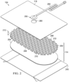
- FIG 2 is an assembly view of an example of the dressing 104 of Figure 1 , illustrating additional details that may be associated with some embodiments in which the tissue interface 114 comprises multiple layers.
- the tissue interface 114 includes a debridement tool or contact layer 202 and a film layer 204.
- the contact layer 202 has a first surface 206, a second surface 208, and a plurality of through-holes 210 extending through the contact layer 202 from the first surface 206 to the second surface 208.
- the film layer 204 is disposed adjacent to the second surface 208 of the contact layer 202. In some embodiments, the film layer 204 can be coupled to the second surface 208 of the contact layer 202.
- the contact layer 202 may have a substantially uniform thickness 212.
- the thickness 212 may be between about 7 mm and about 15 mm. In other embodiments, the thickness 212 may be thinner or thicker than the stated range as needed for the tissue site. In a preferred embodiment, the thickness 212 may be about 8 mm. In some embodiments, individual portions of the contact layer 202 may have a minimal tolerance from the thickness 212. In some embodiments, the thickness 212 may have a tolerance of about 2 mm. In some embodiments, the thickness 212 may be between about 6 mm and about 10 mm.
- the contact layer 202 may be flexible so that the contact layer 202 can be contoured to a surface of the tissue site.
- the contact layer 202 may be formed from thermoplastic elastomers (TPE), such as styrene ethylene butylene styrene (SEBS) copolymers, or thermoplastic polyurethane (TPU).
- TPE thermoplastic elastomers
- SEBS styrene ethylene butylene styrene
- TPU thermoplastic polyurethane
- the contact layer 202 may be formed by combining sheets of TPE or TPU.
- the sheets of TPE or TPU may be bonded, welded, adhered, or otherwise coupled to one another.
- the sheets of TPE or TPU may be welded using radiant heat, radio-frequency welding, or laser welding.
- the contact layer 202 may be formed from a 3D textile, also referred to as a spacer fabric. Suitable 3D textiles may be produced by Heathcoat Fabrics, Ltd., Baltex, and Mueller Textil Group.
- the contact layer 202 can also be formed from polyurethane, silicone, polyvinyl alcohol, and metals, such as copper, tin, silver or other beneficial metals.
- the contact layer 202 may be formed from a foam.
- cellular foam, open-cell foam, reticulated foam, or porous tissue collections may be used to form the contact layer 202.
- the contact layer 202 may be formed of V.A.C. ® GRANUFOAM TM Dressing, grey foam, or Zotefoam.
- Grey foam may be a polyester polyurethane foam having about 60 pores per inch (ppi).
- Zotefoam may be a closed-cell crosslinked polyolefin foam.
- the contact layer 202 may be an open-cell, reticulated polyurethane foam such as V.A.C.
- the contact layer 202 may be an open-cell, reticulated polyurethane foam such as a V.A.C. VERAFLO TM dressing, also available from Kinetic Concepts, Inc., of San Antonio, Texas.
- the contact layer 202 is formed from a foam that is mechanically or chemically compressed to increase the density of the foam at ambient pressure.
- a foam that is mechanically or chemically compressed may be referred to as a compressed foam.
- a compressed foam may be characterized by a firmness factor (FF) that is defined as a ratio of the density of a foam in a compressed state to the density of the same foam in an uncompressed state.
- FF firmness factor
- 5 may refer to a compressed foam having a density at ambient pressure that is five times greater than a density of the same foam in an uncompressed state at ambient pressure.
- Mechanically or chemically compressing a foam may reduce a thickness of the foam at ambient pressure when compared to the same foam that has not been compressed.
- a thickness of a foam by mechanical or chemical compression may increase a density of the foam, which may increase the firmness factor (FF) of the foam.
- FF firmness factor
- Increasing the firmness factor (FF) of a foam may increase a stiffness of the foam in a direction that is parallel to a thickness of the foam.
- increasing a firmness factor (FF) of the contact layer 202 may increase a stiffness of the contact layer 202 in a direction that is parallel to the thickness 212 of the contact layer 202.
- a compressed foam may be a compressed V.A.C. ® GRANUFOAM TM Dressing. V.A.C.
- V.A.C. ® GRANUFOAM TM Dressing may have a density of about 0.03 grams per centimeter 3 (g/cm 3 ) in its uncompressed state. If the V.A.C. ® GRANUFOAM TM Dressing is compressed to have a firmness factor (FF) of 5, the V.A.C. ® GRANUFOAM TM Dressing may be compressed until the density of the V.A.C. ® GRANUFOAM TM Dressing is about 0.15g/cm 3 . V.A.C. VERAFLO TM dressing may also be compressed to form a compressed foam having a firmness factor (FF) up to 5.
- FF firmness factor
- the contact layer 202 may have a thickness between about 4 mm to about 15 mm, and more specifically, about 8 mm at ambient pressure. In an exemplary embodiment, if the thickness 212 of the contact layer is about 8 mm, and the contact layer 202 is positioned within the sealed environment and subjected to negative pressure of about -115 mmHg to about -135 mm Hg, the thickness 212 of the contact layer 202 may be between about 1 mm and about 5 mm and, generally, greater than about 3 mm.
- a compressed foam is referred to as a felted foam.
- a felted foam undergoes a thermoforming process to permanently compress the foam to increase the density of the foam.
- a felted foam may also be compared to other felted foams or compressed foams by comparing the firmness factor of the felted foam to the firmness factor of other compressed or uncompressed foams. Generally a compressed or felted foam may have a firmness factor greater than 1.
- the firmness factor (FF) may also be used to compare compressed foam materials with non-foam materials.
- a Supracor ® material may have a firmness factor (FF) that allows Supracor ® to be compared to compressed foams.
- the firmness factor (FF) for a non-foam material may represent that the non-foam material has a stiffness that is equivalent to a stiffness of a compressed foam having the same firmness factor.
- the contact layer may have a stiffness that is about the same as the stiffness of a compressed V.A.C. ® GRANUFOAM TM Dressing material having a firmness factor (FF) of 3.
- the compressed foam exhibits less deformation than a similar uncompressed foam.
- the contact layer 202 is formed of a compressed foam
- the thickness 212 of the contact layer 202 may deform less than if the contact layer 202 is formed of a comparable uncompressed foam.
- the decrease in deformation may be caused by the increased stiffness as reflected by the firmness factor (FF).
- FF firmness factor
- the contact layer 202 that is formed of compressed foam may flatten less than the contact layer 202 that is formed from uncompressed foam.
- the foam material used to form a compressed foam may be either hydrophobic or hydrophilic.
- the foam material used to form a compressed foam may also be either reticulated or un-reticulated.
- the pore size of a foam material may vary according to needs of the contact layer 202 and the amount of compression of the foam. For example, in some embodiments, an uncompressed foam may have pore sizes in a range of about 400 microns to about 600 microns. If the same foam is compressed, the pore sizes may be smaller than when the foam is in its uncompressed state.
- the film layer 204 is a film of a material having antimicrobial and/or antibacterial properties.
- the film layer 204 can be formed from a mixture containing silver, citric acid, acetic acid, or a combination thereof.
- the film layer 204 can be a coating of silver, a film of citric acid, or a film of acetic acid.
- the contact layer 202 may be an open-cell reticulated foam having a thin layer of silver coated onto the foam to form the film layer 204.
- the reticulated, open-cell structure of the foam may be maintained after the coating process.
- the foam may have pore sizes in the range of about 400 microns to about 600 microns.
- the silver coating of the film layer 204 may have a thickness of about 1 micron to about 10 microns and, in particular, about 3 microns. In some embodiments, the coating of silver may extend through the open-cell reticulated foam of the contact layer 202 so that substantially all surfaces of the contact layer 202 may be coated. In other embodiments, the silver coating of the film layer 204 may only be applied to a portion of the contact layer 202 or to the second surface 208 of the contact layer 202. The silver coating may be 99.9% pure metallic silver that is bonded to the contact layer 202. In some embodiments, the contact layer 202 may be felted or un-felted V.A.C. ® GRANUFOAM SILVER TM Dressing available from KCI, Inc.
- the film layer 204 can be formed from acetic acid.
- the film layer 204 can be a 100 millimolar (“mM”) acetic acid.
- mM millimolar
- 2.0 grams of collagen and oxidized regenerated cellulose (“ORC”) can be placed in 200 milliliters ("mL") of 0.05 molarity (“M”) acetic acid.
- the collagen/ORC can absorb or swell with the acetic acid for about 5 minutes. Mixing of the collagen/ORC and the acetic acid can be followed by the addition of glycerol.
- the glycerol can be added by drop and mixed until a concentration of the solution ("v/v") is approximately 300 microliters (" ⁇ L") of glycerol per 100 mL of acetic acid or 0.3% v/v. In the example embodiment, about 600 ⁇ L of glycerol were added to the 200 mL of acetic acid.
- the resulting solution can be mixed and placed in a vacuum chamber to draw out gas bubbles from the solution.
- the solution can be placed into trays in about 20 mL quantities and incubated at 37 °C to produce a film having a thickness between about 100 microns and about 500 microns.
- the film layer 204 can be coated onto the second surface 208 of the contact layer 202.
- the second surface 208 of the contact layer 202 can be placed into a tray having the solution while the solution cures into the film layer 204.
- the acetic acid can be produced in the ratios described to produce sheets of film. The sheets can be positioned over the contact layer 202 and placed in contact with the contact layer 202. The natural tackiness of the acetic acid sheet can couple the sheet to the contact layer 202.
- the tackiness of the acetic acid sheet of the film layer 204 can bond the sheet to the contact layer 202.
- the film layer 204 can cover the through-holes 210 of the contact layer 202.
- the film layer 204 can be removed from the contact layer 202 at the plurality of through-holes 210, leaving the film layer 204 coating the walls 302 of the second surface 208.
- the through-holes 210 of the contact layer 202 can be formed after the film layer 204 is coupled to the contact layer 202.
- the film layer 204 can be formed from citric acid.
- the film layer 204 can be a 100 millimolar ("mM") citric acid.
- citric acid powder can be dissolved into water or other similar solution.
- Glycerol can be titrated into the citric acid as described above to produce sheets of the citric acid film.
- the process produced an exemplary 100 mM citric acid solution and an exemplary 200 mM citric acid solution.
- the 100 mM citric acid solution had a formula weight of about 129.12 Daltons, a volume of 110 mL, and a mass of about 2.1 grams.
- the film layer 204 can be coated onto the second surface 208 of the contact layer 202.
- the film layer 204 can cover the through-holes 210 of the contact layer 202.
- the film layer 204 can be removed from the contact layer 202 at the plurality of through-holes 210.
- the dressing 104 may include a release liner 245 to protect an optional adhesive on a portion of the cover 116 prior to use.
- the release liner 245 may also provide stiffness to assist with, for example, deployment of the dressing 104.
- the release liner 245 may be, for example, a casting paper, a film, or polyethylene.
- the release liner 245 may be a polyester material such as polyethylene terephthalate (PET), or similar polar semi-crystalline polymer.
- PET polyethylene terephthalate
- the use of a polar semi-crystalline polymer for the release liner 245 may substantially preclude wrinkling or other deformation of the dressing 104.
- the polar semi-crystalline polymer may be highly orientated and resistant to softening, swelling, or other deformation that may occur when brought into contact with components of the dressing 104, or when subjected to temperature or environmental variations, or sterilization.
- a release agent may be disposed on a side of the release liner 245 that is configured to contact the tissue interface 114.
- the release agent may be a silicone coating and may have a release factor suitable to facilitate removal of the release liner 245 by hand and without damaging or deforming the dressing 104.
- the release agent may be a fluorocarbon or a fluorosilicone, for example.
- the release liner 245 may be uncoated or otherwise used without a release agent.
- Figure 2 also illustrates one example of a fluid conductor 250 and a dressing interface 255.
- the fluid conductor 250 may be a flexible tube, which can be fluidly coupled on one end to the dressing interface 255.
- the dressing interface 255 may be an elbow connector, as shown in the example of Figure 2 , which can be placed over an aperture 260 in the cover 116 to provide a fluid path between the fluid conductor 250 and the tissue interface 114.
- Figure 3 is a plan view, illustrating additional details that may be associated with some embodiments of the contact layer 202.
- the contact layer 202 includes a plurality of through-holes 210 or other perforations extending through the contact layer 202 to form walls 302.
- an exterior surface of the walls 302 may be parallel to sides of the contact layer 202.
- an interior surface of the walls 302 may be generally perpendicular to the second surface 208 and the first surface 206 of the contact layer 202.
- the exterior surface or surfaces of the walls 302 may be coincident with the second surface 208 and the first surface 206.
- the interior surface or surfaces of the walls 302 may form a perimeter 304 of each through-hole 210 and may connect the second surface 208 to the first surface 206.
- the through-holes 210 may have a circular shape as shown.
- the through-holes 210 may have diameters between about 5 mm and about 20 mm, and in some embodiments, the diameters of the through-holes 210 may be about 10 mm.
- the through-holes 210 may have a depth that is about equal to the thickness 212 of the contact layer 202.
- the through-holes 210 may have a depth between about 6 mm to about 10 mm, and more specifically, about 8 mm at ambient pressure.
- the contact layer 202 may have a first orientation line 306 and a second orientation line 308 that is perpendicular to the first orientation line 306.
- the first orientation line 306 and the second orientation line 308 may be lines of symmetry of the contact layer 202.
- a line of symmetry may be, for example, an imaginary line across the second surface 208 or the first surface 206 of the contact layer 202 defining a fold line such that if the contact layer 202 is folded on the line of symmetry, the through-holes 210 and walls 302 would be coincidentally aligned.
- the first orientation line 306 and the second orientation line 308 aid in the description of the contact layer 202.
- the first orientation line 306 and the second orientation line 308 may be used to refer to the desired directions of contraction of the contact layer 202.
- the desired direction of contraction may be parallel to the second orientation line 308 and perpendicular to the first orientation line 306.
- the desired direction of contraction may be parallel to the first orientation line 306 and perpendicular to the second orientation line 308.
- the desired direction of contraction may be at a non-perpendicular angle to both the first orientation line 306 and the second orientation line 308.
- the contact layer 202 may not have a desired direction of contraction.
- the contact layer 202 may be placed at the tissue site so that the second orientation line 308 extends across debris located at the tissue site.
- the contact layer 202 is shown as having a generally rectangular shape including longitudinal edges 310 and circular edges 312, the contact layer 202 may have other shapes.
- the contact layer 202 may have a diamond, square, or circular shape.
- the shape of the contact layer 202 may be selected to accommodate the type of tissue site being treated.
- the contact layer 202 may have an oval or circular shape to accommodate an oval or circular tissue site.
- the first orientation line 306 may be parallel to the longitudinal edges 310.
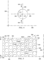
- FIG 4 is a plan view illustrating additional details that may be associated with some embodiments of the through-hole 210 of the contact layer 202 of Figure 3 .
- a single through-hole 210 having a circular shape is shown.
- the through-hole 210 may include a center 402 and the perimeter 304.
- the through-hole 210 may have a perforation shape factor (PSF).
- the perforation shape factor (PSF) may represent an orientation of the through-hole 210 relative to the first orientation line 306 and the second orientation line 308.
- the perforation shape factor is a ratio of 1 ⁇ 2 a maximum length of the through-hole 210 that is parallel to the desired direction of contraction to 1 ⁇ 2 a maximum length of the through-hole 210 that is perpendicular to the desired direction of contraction.
- the desired direction of contraction is parallel to the second orientation line 308.
- the desired direction of contraction may be indicated by a lateral force 404.
- the through-hole 210 may have an X-axis 406 extending through the center 402 parallel to the first orientation line 306, and a Y-axis 408 extending through the center 402 parallel to the second orientation line 308.
- the perforation shape factor (PSF) of the through-hole 210 may be defined as a ratio of a line segment 410 on the Y-axis 408 extending from the center 402 to the perimeter 304 of the through-hole 210, to a line segment 412 on the X-axis 406 extending from the center 402 to the perimeter 304 of the through-hole 210. If a length of the line segment 410 is 2.5 mm and the length of the line segment 412 is 2.5 mm, the perforation shape factor (PSF) would be 1.
- the through-holes 210 may have other shapes and orientations, for example, oval, hexagonal, square, triangular, or amorphous or irregular and be oriented relative to the first orientation line 306 and the second orientation line 308 so that the perforation shape factor (PSF) may range from about 0.5 to about 1.10.
- PSF perforation shape factor
- Figure 5 is a plan view illustrating additional details of a portion of the contact layer 202 of Figure 3 .
- the contact layer 202 may include the plurality of through-holes 210 aligned in parallel rows to form an array.
- the array of through-holes 210 may include a first row 502 of the through-holes 210, a second row 504 of the through-holes 210, and a third row 506 of the through-holes 210.
- a width of the wall 302 between the perimeters 304 of adjacent the through-holes 210 in a row, such as the first row 502 may be about 5 mm.
- the centers 402 of the through-holes 210 in adjacent rows may be characterized by being offset from the second orientation line 308 along the first orientation line 306.
- a line connecting the centers of adjacent rows may form a strut angle (SA) with the first orientation line 306.
- SA strut angle
- a first through-hole 210A in the first row 502 may have a center 402A
- a second through-hole 210B in the second row 504 may have a center 402B.
- a strut line 508 may connect the center 402A with the center 402B.
- the strut line 508 may form an angle 510 with the first orientation line 306.
- the angle 510 may be the strut angle (SA) of the contact layer 202.
- the strut angle (SA) may be less than about 90°.
- the strut angle (SA) may be between about 30° and about 70° relative to the first orientation line 306.
- the strut angle (SA) may be about 66° from the first orientation line 306.
- a stiffness of the contact layer 202 in a direction parallel to the first orientation line 306 may increase. Increasing the stiffness of the contact layer 202 parallel to the first orientation line 306 may increase the compressibility of the contact layer 202 perpendicular to the first orientation line 306.
- the contact layer 202 may be more compliant or compressible in a direction perpendicular to the first orientation line 306.
- the contact layer 202 may collapse to apply the lateral force 404 to the tissue site described in more detail below.
- the centers 402 of the through-holes 210 in alternating rows may be spaced from each other parallel to the second orientation line 308 by a length 512.
- the length 512 may be greater than an effective diameter of the through-hole 210. If the centers 402 of through-holes 210 in alternating rows are separated by the length 512, the exterior surface of the walls 302 parallel to the first orientation line 306 may be considered continuous. Generally, the exterior surface of the walls 302 may be continuous if the exterior surface of the walls 302 do not have any discontinuities or breaks between through-holes 210.
- the length 512 may be between about 7 mm and about 25 mm.
- the through-holes 210 in the contact layer 202 may leave void spaces in the contact layer 202 and on the second surface 208 and the first surface 206 of the contact layer 202 so that only the exterior surface of the walls 302 of the contact layer 202 remain with a surface available to contact the tissue site. It may be desirable to minimize the exterior surface of the walls 302 so that the through-holes 210 may collapse, causing the contact layer 202 to collapse and generate the lateral force 404 in a direction perpendicular to the first orientation line 306. However, it may also be desirable not to minimize the exterior surface of the walls 302 so much that the contact layer 202 becomes too fragile for sustaining the application of a negative pressure.
- the void space percentage (VS) of the through-holes 210 may be equal to the percentage of the volume or surface area of the void spaces of the second surface 208 created by the through-holes 210 to the total volume or surface area of the second surface 208 of the contact layer 202. In some embodiments, the void space percentage (VS) may be between about 40% and about 75%. In other embodiments, the void space percentage (VS) may be about 55%.
- the organization of the through-holes 210 can also impact the void space percentage (VS), influencing the total surface area of the contact layer 202 that may contact the tissue site. In some embodiments, the longitudinal edge 310 and the circular edge 312 of the contact layer 202 may be discontinuous.
- An edge may be discontinuous where the through-holes 210 overlap an edge causing the edge to have a non-linear profile.
- a discontinuous edge may reduce the disruption of keratinocyte migration and enhance re-epithelialization while negative pressure is applied to the dressing 104.
- the through-holes 210 of the contact layer 202 may have a depth that is less than the thickness 212 of the contact layer 202.
- the through-holes 210 may be blind holes formed in the second surface 208 of the contact layer 202.
- the through-holes 210 may leave void spaces in the contact layer 202 on the second surface 208 so that only the exterior surface of the walls 302 of the contact layer 202 on the second surface 208 remain with a surface available to contact the tissue site at ambient pressure.
- the void space percentage (VS) of the first surface 206 may be zero, while the void space percentage (VS) of the second surface 208 is greater than zero, for example 55%.
- the through-holes 210 may be formed during molding of the contact layer 202. In other embodiments, the through-holes 210 may be formed by cutting, melting, drilling, or vaporizing the contact layer 202 after the contact layer 202 is formed. For example, the through-holes 210 may be formed in the contact layer 202 by laser cutting the compressed foam of the contact layer 202. In some embodiments, the through-holes 210 may be formed so that the interior surfaces of the walls 302 of the through-holes 210 are parallel to the thickness 212. In other embodiments, the through-holes 210 may be formed so that the interior surfaces of the walls 302 of the through-holes 210 form a non-perpendicular angle with the second surface 208.
- the interior surfaces of the walls 302 of the through-holes 210 may taper toward the center 402 of the through-holes 210 to form conical, pyramidal, or other irregular through-hole shapes. If the interior surfaces of the walls 302 of the through-holes 210 taper, the through-holes 210 may have a height less than the thickness 212 of the contact layer 202.
- formation of the through-holes 210 may thermoform the material of the contact layer 202, for example a compressed foam or a felted foam, causing the interior surface of the walls 302 extending between the second surface 208 and the first surface 206 to be smooth.
- smoothness may refer to the formation of the through-holes 210 that causes the interior surface of the walls 302 that extends between the second surface 208 and the first surface 206 to be substantially free of pores if compared to an uncut portion of the contact layer 202.
- laser-cutting the through-holes 210 into the contact layer 202 may plastically deform the material of the contact layer 202, closing any pores on the interior surfaces of the walls 302 that extend between the second surface 208 and the first surface 206.
- a smooth interior surface of the walls 302 may limit or otherwise inhibit ingrowth of tissue into the contact layer 202 through the through-holes 210.
- the smooth interior surfaces of the walls 302 may be formed by a smooth material or a smooth coating.
- an effective diameter of the through-holes 210 may be selected to permit flow of particulates through the through-holes 210.
- the diameter of the through-holes 210 may be selected based on the size of the solubilized debris to be lifted from the tissue site. Larger through-holes 210 may allow larger debris to pass through the contact layer 202, and smaller through-holes 210 may allow smaller debris to pass through the contact layer 202 while blocking debris larger than the through-holes.
- successive applications of the dressing 104 can use contact layers 202 having successively smaller diameters of the through-holes 210 as the size of the solubilized debris in the tissue site decreases.
- Sequentially decreasing diameters of the through-holes 210 may also aid in fine tuning a level of tissue disruption to the debris during the treatment of the tissue site.
- the diameter of the through-holes 210 can also influence fluid movement in the contact layer 202 and the dressing 104.
- the contact layer 202 can channel fluid in the dressing 104 toward the through-holes 210 to aid in the disruption of the debris on the tissue site.
- Variation of the diameters of the through-holes 210 can vary how fluid is moved through the dressing 104 with respect to both the removal of fluid and the application of negative pressure.
- the effective diameter of the through-holes 210 is between about 5 mm and about 20 mm and, more specifically, about 10 mm.
- An effective diameter of a non-circular area is defined as a diameter of a circular area having the same surface area as the non-circular area.
- each through-hole 210 may have an effective diameter of about 3.5 mm. In other embodiments, each through-hole 210 may have an effective diameter between about 5 mm and about 20 mm.
- the effective diameter of the through-holes 210 should be distinguished from the porosity of the material forming the walls 302 of the contact layer 202. Generally, an effective diameter of the through-holes 210 is an order of magnitude larger than the effective diameter of the pores of a material forming the contact layer 202.
- the effective diameter of the through-holes 210 may be larger than about 1 mm, while the walls 302 may be formed from V.A.C. ® GRANUFOAM TM Dressing having a pore size less than about 600 microns.
- the pores of the walls 302 may not create openings that extend all the way through the material.
- the through-holes 210 do not include pores formed by the foam formation process, and the through-holes 210 may have an average effective diameter that is greater than ten times an average effective diameter of pores of a material.
- the through-holes 210 may form a pattern depending on the geometry of the through-holes 210 and the alignment of the through-holes 210 between adjacent and alternating rows in the contact layer 202 with respect to the first orientation line 306. If the contact layer 202 is subjected to negative pressure, the through-holes 210 of the contact layer 202 may contract. As used herein, contraction can refer to both vertical compression of a body parallel to a thickness of the body, such as the contact layer 202, and lateral compression of a body perpendicular to a thickness of the body, such as the contact layer 202.
- the void space percentage (VS), the perforation shape factor (PSF), and the strut angle (SA) may cause the contact layer 202 to contract along the second orientation line 308 perpendicular to the first orientation line 306 as shown in more detail in Figure 6 .
- Figure 6 is a plan view illustrating additional details of the contact layer 202 of Figure 3 in a contracted state. If the contact layer 202 is positioned on the tissue site, the contact layer 202 may generate the lateral force 404 along the second orientation line 308, contracting the contact layer 202, as shown in more detail in Figure 6 .
- the lateral force 404 may be optimized by adjusting the factors described above as set forth in Table 1 below.
- the through-holes 210 may be circular, have a strut angle (SA) of approximately 37°, a void space percentage (VS) of about 54%, a firmness factor (FF) of about 5, a perforation shape factor (PSF) of about 1, and a diameter of about 5 mm.
- SA strut angle
- VS void space percentage
- FF firmness factor
- PSF perforation shape factor
- the contact layer 202 asserts the lateral force 404 of approximately 11.9 N. If the diameter of the through-holes 210 of the contact layer 202 is increased to about 20 mm, the void space percentage (VS) changed to about 52%, the strut angle (SA) changed to about 52°, and the perforation shape factor (PSF) and the firmness factor (FF) remain the same, the lateral force 404 is decreased to about 6.5 N.
- the through-holes 210 may be hexagonal, have a strut angle (SA) of approximately 66°, a void space percentage (VS) of about 55%, a firmness factor (FF) of about 5, a perforation shape factor (PSF) of about 1.07, and an effective diameter of about 5 mm. If the contact layer 202 is subjected to a negative pressure of about -125 mmHg, the lateral force 404 asserted by the contact layer 202 is about 13.3 N. If the effective diameter of the through-holes 210 of the contact layer 202 is increased to 10 mm, the lateral force 404 is decreased to about 7.5 N.
- SA strut angle
- VS void space percentage
- FF firmness factor
- PSF perforation shape factor
- the contact layer 202 is in the second position, or contracted position, as indicated by the lateral force 404.
- negative pressure is supplied to the sealed environment with the negative-pressure source 102.
- the contact layer 202 contracts from the relaxed position illustrated in Figure 3 to the contracted position illustrated in Figure 6 .
- the thickness 212 of the contact layer 202 remains substantially the same.
- the contact layer 202 expands back to the relaxed position. If the contact layer 202 is cycled between the contracted and relaxed positions of Figures 6 and Figure 3 , respectively, the second surface 208 of the contact layer 202 may disrupt the debris on the tissue site by rubbing the debris from the tissue site.
- edges of the through-holes 210 formed by the second surface 208 and the interior surfaces or transverse surfaces of the walls 302 can form cutting edges that can disrupt the debris in the tissue site, allowing the debris to exit through the through-holes 210.
- the cutting edges are defined by the perimeter 304 where each through-hole 210 intersects the second surface 208.
- the material, the void space percentage (VS), the firmness factor, the strut angle, the hole shape, the perforation shape factor (PSF), and the hole diameter may be selected to increase compression or collapse of the contact layer 202 in a lateral direction, as shown by the lateral force 404, by forming weaker walls 302.
- the factors may be selected to decrease compression or collapse of the contact layer 202 in a lateral direction, as shown by the lateral force 404, by forming stronger walls 302.
- the factors described herein can be selected to decrease or increase the compression or collapse of the contact layer 202 perpendicular to the lateral force 404.
- the therapy system 100 may provide cyclic therapy. Cyclic therapy may alternately apply negative pressure to and vent negative pressure from a sealed space or sealed environment containing the tissue interface 114. In some embodiments, negative pressure may be supplied to the tissue site until the pressure in the sealed environment reaches a predetermined therapy pressure. If negative pressure is supplied to the sealed environment, the debris and the subcutaneous tissue underlying the debris may be drawn into the through-holes 210. In some embodiments, the sealed environment may remain at the therapy pressure for a predetermined therapy period such as, for example, about 10 minutes. In other embodiments, the therapy period may be longer or shorter as needed to supply appropriate negative-pressure therapy to the tissue site.
- a predetermined therapy period such as, for example, about 10 minutes. In other embodiments, the therapy period may be longer or shorter as needed to supply appropriate negative-pressure therapy to the tissue site.
- the sealed environment may be vented.
- the negative-pressure source 102 may fluidly couple the sealed environment to the atmosphere (not shown), allowing the sealed environment to return to ambient pressure.
- the negative-pressure source 102 may vent the sealed environment for about 1 minute. In other embodiments, the negative-pressure source 102 may vent the sealed environment for longer or shorter periods. After venting of the sealed environment, the negative-pressure source 102 may be operated to begin another negative-pressure therapy cycle.
- instillation therapy may be combined with negative-pressure therapy.
- the solution source 118 may operate to provide fluid to the sealed environment.
- the solution source 118 may provide fluid while the negative-pressure source 102 vents the sealed environment.
- the positive-pressure source 120 may be configured to move instillation fluid from the solution source 118 to the sealed environment.
- the solution source 118 may not have a pump and may operate using a gravity feed system.
- the negative-pressure source 102 may not vent the sealed environment. Instead, the negative pressure in the sealed environment is used to draw instillation fluid from the solution source 118 into the sealed environment.
- the solution source 118 may provide a volume of fluid to the sealed environment.
- the volume of fluid may be the same as a volume of the sealed environment.
- the volume of fluid may be smaller or larger than the sealed environment as needed to appropriately apply instillation therapy. Instilling of the tissue site may raise a pressure in the sealed environment to a pressure greater than the ambient pressure, for example to between about 0 mmHg and about 15 mmHg and, more specifically, about 5 mmHg.
- the fluid provided by the solution source 118 may remain in the sealed environment for a dwell time.
- the dwell time is about 5 minutes.
- the dwell time may be longer or shorter as needed to appropriately administer instillation therapy to the tissue site.
- the dwell time may be zero.
- the negative-pressure source 102 may be operated to draw the instillation fluid into the container, completing a cycle of therapy.
- negative pressure may also be supplied to the sealed environment, starting another cycle of therapy.
- Figure 7 is a sectional view of a portion of the contact layer 202, illustrating additional details that may be associated with some embodiments.
- the contact layer 202 and the film layer 204 may be placed at a tissue site 702 having debris 704 covering subcutaneous tissue 706.
- the film layer 204 may be adjacent to the debris 704 and the contact layer 202 adjacent to the film layer 204.
- the second surface 208 of the contact layer 202 may be positioned adjacent to the debris 704.
- the cover 116 may be placed over the contact layer 202 and the film layer 204 to provide a sealed environment for the application of negative-pressure therapy or instillation therapy.
- Figure 8 is a sectional view of a portion of the dressing 104 during negative-pressure therapy, illustrating additional details that may be associated with some embodiments.
- Figure 8 may illustrate a moment in time where a pressure in the sealed environment may be about 125 mmHg of negative pressure.
- the contact layer 202 may be a precompressed or felted foam. In response to the application of negative pressure, the contact layer 202 may not compress.
- negative pressure in the sealed environment can generate concentrated stresses in the debris 704 adjacent to the through-holes 210 in the contact layer 202. The concentrated stresses can cause macro-deformations of the debris 704 and the subcutaneous tissue 706 that draws portions of the debris 704 and the subcutaneous tissue 706 into the through-holes 210.
- the film layer 204 can be drawn into the through-holes 210, remaining in contact with the debris 704.
- Figure 9 is a detail view of the contact layer 202, illustrating additional details of the operation of the contact layer 202 during negative-pressure therapy.
- the through-holes 210 of the contact layer 202 may create macro-pressure points in portions of the film layer 204, the debris 704, and the subcutaneous tissue 706 that are in contact with the second surface 208 of the contact layer 202, causing tissue puckering and nodules 902 in the film layer 204, the debris 704, and the subcutaneous tissue 706.
- a height of the nodules 902 over the surrounding tissue may be selected to maximize disruption of debris 704 and minimize damage to subcutaneous tissue 706 or other desired tissue.
- the pressure in the sealed environment can exert a force that is proportional to the area over which the pressure is applied.
- the force may be concentrated as the resistance to the application of the pressure is less than in the walls 302 of the contact layer 202.
- the debris and the subcutaneous tissue 706 that forms the nodules 902 may be drawn into and through the through-holes 210 until the force applied by the pressure is equalized by the reactive force of the film layer 204, the debris 704, and the subcutaneous tissue 706.
- the thickness 212 of the contact layer 202 may be selected to limit the height of the nodules 902 over the surrounding tissue. In some embodiments, the height of the nodules 902 may be limited to a height that is less than the thickness 212 of the contact layer 202. In an exemplary embodiment, the thickness 212 of the contact layer 202 may be about 7 mm. During the application of negative pressure, the height of the nodules 902 may be limited to about 2 mm to about 7 mm. By controlling the height of the nodules 902 by controlling the thickness 212 of the contact layer 202, the aggressiveness of disruption to the debris 704 and tearing can be controlled.
- the height of the nodules 902 can also be controlled by controlling an expected compression of the contact layer 202 during negative-pressure therapy.
- the contact layer 202 may have a thickness 212 of about 8 mm. If the contact layer 202 is formed from a compressed foam, the firmness factor of the contact layer 202 may be higher; however, the contact layer 202 may still reduce in thickness in response to negative pressure in the sealed environment. In one embodiment, application of negative pressure of between about -50 mmHg and about -350 mmHg, between about -100 mm Hg and about -250 mmHg and, more specifically, about - 125 mmHg in the sealed environment may reduce the thickness 212 of the contact layer 202 from about 8 mm to about 3 mm.
- the height of the nodules 902 may be limited to be no greater than the thickness 212 of the contact layer 202 during negative-pressure therapy, for example, about 3 mm. By controlling the height of the nodules 902, the forces applied to the debris 704 by the contact layer 202 can be adjusted and the degree that the debris 704 is stretched can be varied.
- the formation of the nodules 902 can cause the debris 704 to remain in contact with a tissue interface 114 during negative pressure therapy.
- the nodules 902 may contact the sidewalls of the through-holes 210 of the contact layer 202, while the surrounding tissue may contact the film layer 204 coating the second surface 208 of the contact layer 202.
- the film layer 204 may be in contact with the debris 704 throughout therapy.
- the film layer 204 can provide a continuous application of antimicrobial/antibacterial agents to the debris 704, allowing the antimicrobial/antibacterial properties of the film layer 204 to remain effective throughout therapy.
- formation of the nodules 902 may lift debris 704 and particulates off of the surrounding tissue, operating in a piston-like manner to move debris 704 toward the retainer layer 1002 and out of the sealed environment.
- the debris 704 and the subcutaneous tissue 706 may leave the through-holes 210, returning to the position shown in Figure 7
- repeated application of negative-pressure therapy and instillation therapy while the contact layer 202 is disposed over the debris 704 may disrupt the debris 704, allowing the debris 704 to be removed during dressing changes.
- the contact layer 202 may disrupt the debris 704 so that the debris 704 can be removed by negative pressure.
- the contact layer 202 may disrupt the debris 704, aiding removal of the debris 704 during debridement processes.
- the contact layer 202 may form nodules 902 in the debris 704. The formation of the nodules 902 and release of the nodules 902 by the contact layer 202 during therapy may disrupt the debris. With each subsequent cycle of therapy, disruption of the debris 704 can be increased.
- Disruption of the debris 704 can be caused, at least in part, by the concentrated forces applied to the debris 704 by the through-holes 210 and the walls 302 of the contact layer 202.
- the forces applied to the debris 704 can be a function of the negative pressure supplied to the sealed environment and the area of each through-hole 210. For example, if the negative pressure supplied to the sealed environment is about 125 mmHg and the diameter of each through-hole 210 is about 5 mm, the force applied at each through-hole 210 is about 0.07 lbs. If the diameter of each through-hole 210 is increased to about 8 mm, the force applied at each through-hole 210 can increase up to 6 times. Generally, the relationship between the diameter of each through-hole 210 and the applied force at each through-hole 210 is not linear and can increase exponentially with an increase in diameter.
- the negative pressure applied by the negative-pressure source 102 may be cycled rapidly. For example, negative pressure may be supplied for a few seconds, then vented for a few seconds, causing a pulsation of negative pressure in the sealed environment. The pulsation of the negative pressure can pulsate the nodules 902, causing further disruption of the debris 704.
- the cyclical application of instillation therapy and negative pressure therapy may cause micro-floating.
- negative pressure may be applied to the sealed environment during a negative-pressure therapy cycle.
- instillation fluid may be supplied during the instillation therapy cycle.
- the instillation fluid may cause the contact layer 202 to float relative to the debris.
- the position change may cause the contact layer 202 to engage a slightly different portion of the debris 704 during the next negative-pressure therapy cycle, aiding disruption of the debris 704 and the application of antimicrobial/antibacterial agents by the film layer 204.
- the contact layer 202 may be provided as a component of a dressing kit.
- the kit may include a punch, and the contact layer 202 may be provided without any through-holes 210.
- the user may use the punch to place the through-holes 210 through portions of the contact layer 202 that may be placed over the debris.
- the kit provides a user, such as a clinician, the ability to customize the contact layer 202 to the particular tissue site, so that the through-holes 210 are only disrupting the debris and not healthy tissue that may be near or surround the debris.
- the through-holes 210 of the contact layer 202 may generate concentrated stresses that influence disruption of the debris in different ways. For example, different shapes of the through-holes 210 may also focus the stresses generated by the contact layer 202 in advantageous areas.
- a lateral force, such as the lateral force 404, generated by a contact layer, such as the contact layer 202, may be related to a compressive force generated by applying negative pressure at a therapy pressure to a sealed therapeutic environment.
- the lateral force 404 may be proportional to a product of a therapy pressure (TP) in the sealed environment, the compressibility factor (CF) of the contact layer 202, and a surface area (A) the second surface 208 of the contact layer 202.
- TP therapy pressure
- CF compressibility factor
- A surface area
- the therapy pressure TP is measured in N/m 2
- the compressibility factor (CF) is dimensionless
- the area (A) is measured in m 2
- the lateral force is measured in Newtons (N).
- the compressibility factor (CF) resulting from the application of negative pressure to a contact layer may be, for example, a dimensionless number that is proportional to the product of the void space percentage (VS) of a contact layer, the firmness factor (FF) of the contact layer, the strut angle (SA) of the through-holes in the contact layer, and the perforation shape factor (PSF) of the through-holes in the contact layer.
- the relationship is expressed as follows: Compressibility Factor CF ⁇ VS * FF * sin SA * PSF
- contact layers formed from different materials with through-holes of different shapes were manufactured and tested to determine the lateral force of the contact layers.
- the therapy pressure TP was about -125 mmHg and the dimensions of the contact layer were about 200 mm by about 53 mm so that the surface area (A) of the tissue-facing surface of the contact layer was about 106 cm 2 or 0.0106 m 2 .
- the lateral force for a Supracor ® contact layer 202 having a firmness factor (FF) of 3 was about 13.3 where the Supracor ® contact layer 202 had hexagonal through-holes 210 with a distance between opposite vertices of 5 mm, a perforation shape factor (PSF) of 1.07, a strut angle (SA) of approximately 66°, and a void space percentage (VS) of about 55%.
- a similarly dimensioned V.A.C. ® GRANUFOAM TM Dressing contact layer 202 generated the lateral force 404 of about 9.1 Newtons (N). TABLE 1 Material VS FF SA Hole Shape PSF Major diam. (mm) Lateral force V.A.C.
- the formulas described above may not precisely describe the lateral forces due to losses in force due to the transfer of the force from the contact layer to the wound.
- the modulus and stretching of the cover 116, the modulus of the tissue site, slippage of the cover 116 over the tissue site, and friction between the contact layer 202 and the tissue site may cause the actual value of the lateral force 404 to be less than the calculated value of the lateral force 404.
- FIG 10 is an assembly view of an example of the dressing 104 of Figure 1 , illustrating additional details that may be associated with some embodiments in which the tissue interface 114 comprises multiple layers.
- the tissue interface 114 can include the contact layer 202, the film layer 204, and a retainer layer 1002.
- the contact layer 202 may have the first surface 206, the second surface 208, the plurality of through-holes 210 extending through the contact layer 202 from the first surface 206 to the second surface 208, and the thickness 212.
- the retainer layer 1002 can have a first surface 1004 and a second surface 1006 on an opposite side of the retainer layer 1002 from the first surface 1004.
- the film layer 204 may be disposed adjacent to the second surface 1006 of the retainer layer 1002.
- the film layer 204 can be coupled to the second surface 1006 of the retainer layer 1002.
- the retainer layer 1002 may be positioned over the contact layer 202. In other embodiments, the retainer layer 1002 may be positioned over the contact layer 202, and if the depth of the tissue site is greater than a thickness of the retainer layer 1002 and the thickness 212 of the contact layer 202 combined, another retainer layer 1002 may be placed over the contact layer 202 and the retainer layer 1002.
- the retainer layer 1002 may be a foam having pore sizes in a range of about 60 microns to about 2000 microns. In other embodiments, the retainer layer 1002 may be a foam having pore sizes in a range of about 400 microns to about 600 microns.
- the tensile strength of the retainer layer 1002 may also vary according to needs of a prescribed therapy. For example, the tensile strength of a foam may be increased for instillation of topical treatment solutions.
- the retainer layer 1002 may be an open-cell, reticulated polyurethane foam such as V.A.C. ® GRANUFOAM TM Dressing available from Kinetic Concepts, Inc.
- the retainer layer 1002 may be an open-cell, reticulated polyurethane foam such as a V.A.C. VERAFLO TM dressing, also available from Kinetic Concepts, Inc., of San Antonio, Texas. In other embodiments, the retainer layer 1002 may be formed of an un-reticulated open-cell foam.
- the retainer layer 1002 may be an open-cell reticulated foam having a thin layer of silver coated onto the foam to form the film layer 204.
- the film layer 204 can be formed from citric acid or acetic acid.
- the film layer 204 can be a 100 millimolar ("mM”) citric acid or a 100 millimolar ("mM”) acetic acid.
- the film layer 204 can be coated onto the second surface 1006 of the retainer layer 1002.
- the second surface 1006 of the retainer layer 1002 can be placed into a tray having the solution of the citric acid or the acetic acid while the solution cures into the film layer 204.
- the solution of the citric acid or the acetic acid can be produced in sheets.
- the sheets can be positioned over the second surface 1006 of the retainer layer 1002 and placed in contact with the second surface 1006.
- the natural tackiness of the citric acid and the acetic acid can couple the sheet to the retainer layer 1002 and form the film layer 204.
- the tackiness of the citric acid or the acetic acid sheet of the film layer 204 can bond the film layer 204 to the retainer layer 1002.
- the dressing 104 may include a release liner 245 to protect an optional adhesive on a portion of the cover 116 prior to use.
- the release liner 245 may also provide stiffness to assist with, for example, deployment of the dressing 104.
- Figure 10 also illustrates one example of a fluid conductor 250 and a dressing interface 255.
- the fluid conductor 250 may be a flexible tube, which can be fluidly coupled on one end to the dressing interface 255.
- the dressing interface 255 may be an elbow connector, as shown in the example of Figure 2 , which can be placed over an aperture 260 in the cover 116 to provide a fluid path between the fluid conductor 250 and the tissue interface 114.
- Figure 11 is a sectional view of a portion of the contact layer 202, illustrating additional details that may be associated with some embodiments.
- the contact layer 202, the film layer 204, and the retainer layer 1002 may be placed at the tissue site 702 having the debris 704 covering the subcutaneous tissue 706.
- the film layer 204 can be coupled to the second surface 1006 of the retainer layer 1002.
- the cover 116 may be placed over the retainer layer 1002 to provide the sealed environment for the application of negative-pressure therapy or instillation therapy.
- the retainer layer 1002 may have a thickness 1102 if the pressure in the sealed environment is about an ambient pressure. In some embodiments, the thickness 1102 may be about 8 mm. In other embodiments, the thickness 1102 may be about 16 mm.
- Figure 12 is a sectional view of a portion of the dressing 104 during negative-pressure therapy, illustrating additional details that may be associated with some embodiments.
- Figure 12 may illustrate a moment in time where a pressure in the sealed environment may be about 125 mmHg of negative pressure.
- the retainer layer 1002 may be a non-felted foam, and the contact layer 202 may be a felted foam.
- the contact layer 202 may not compress, and the retainer layer 1002 may compress so that the manifold has a thickness 1202.
- the thickness 1202 of the retainer layer 1002 during negative-pressure therapy may be less than the thickness 1102 of the retainer layer 1002 if the pressure in the sealed environment is about the ambient pressure.
- negative pressure in the sealed environment can generate concentrated stresses in the retainer layer 1002 and the film layer 204 adjacent to the through-holes 210 in the contact layer 202.
- the concentrated stresses can cause macro-deformation of the retainer layer 1002 and the film layer 204 that draws portions of the retainer layer 1002 and the film layer 204 into the through-holes 210 of the contact layer 202.
- negative pressure in the sealed environment can generate concentrated stresses in the debris 704 adjacent to the through-holes 210 in the contact layer 202.
- the concentrated stresses can cause macro-deformations of the debris 704 and the subcutaneous tissue 706 that draws portions of the debris 704 and the subcutaneous tissue 706 into the through-holes 210.
- Figure 13 is a detail view of the contact layer 202, illustrating additional details of the operation of the contact layer 202 during negative-pressure therapy.
- Portions of the retainer layer 1002 and the film layer 204 in contact with the first surface 206 of the contact layer 202 may be drawn into the through-holes 210 to form bosses 1302.
- the bosses 1302 may have a shape that corresponds to the through-holes 210.
- a height of the bosses 1302 from the retainer layer 1002 may be dependent on the pressure of the negative pressure in the sealed environment, the area of the through-holes 210, and the firmness factor of the retainer layer 1002.
- the through-holes 210 of the contact layer 202 may create macro-pressure points in portions of the debris 704 and the subcutaneous tissue 706 that are in contact with the second surface 208 of the contact layer 202, causing tissue puckering and formation of the nodules 902 in the debris 704 and the subcutaneous tissue 706.
- the retainer layer 1002 may limit the height of the nodules 902 to the thickness 212 of the contact layer 202 under negative pressure if the contact layer 202 is compressible.
- the bosses 1302 of the retainer layer 1002 may limit the height of the nodules 902 to a height that is less than the thickness 212 of the contact layer 202.
- the height of the nodules 902 can be limited to the difference of the thickness 212 of the contact layer 202 and the height of the bosses 1302.
- the height of the bosses 1302 can vary from zero to several millimeters as the firmness factor of the retainer layer 1002 decreases.
- the thickness 212 of the contact layer 202 may be about 7 mm.
- the bosses 1302 may have a height between about 4 mm to about 5 mm, limiting the height of the nodules to about 2 mm to about 3 mm.
- the bosses 1302 and the nodules 902 place the debris 704 into contact with the film layer 204.
- the nodules 902 and the bosses 1302 trap the bacterial material that may reside in the debris 704 against the film layer 204 drawn into the through-holes 210 by the bosses 1302.
- portions of the film layer 204 can be drawn into the through-holes 210 by the bosses 1302, positioning the film layer 204 in contact with debris 704.
- the film layer 204 may be spaced from both the tissue site 702 and the cover 116, extending the usable life of the film layer 204.
- the antimicrobial/antibacterial properties of the film layer 204 can apply antimicrobial/antibacterial agents to the debris 704 that limit and inhibit the growth of bacteria, microbes, and other entities that can slow or inhibit healing. Furthermore, as the debris 704 and the tissue are torn or cracked by the application of negative-pressure therapy, the antimicrobial/antibacterial properties of the film layer 204 can prevent the development of infection in the newly opened areas of tissue.
- the nodules 902 and the bosses 1302 may leave the through-holes 210, returning to the position shown in Figure 11 .
- FIG 14 is an assembly view of an example of the dressing 104 of Figure 1 , illustrating additional details that may be associated with some embodiments in which the tissue interface 114 comprises multiple layers.
- the tissue interface 114 can include the contact layer 202 and a cover layer or a retainer layer 1002.
- the contact layer 202 may have the first surface 206, the second surface 208, the plurality of through-holes 210 extending through the contact layer 202 from the first surface 206 to the second surface 208, and the thickness 212.
- the retainer layer 1002 can have the first surface 1004 and the second surface 1006. In some embodiments, the retainer layer 1002 may be positioned over the contact layer 202.
- the retainer layer 1002 may be positioned over the contact layer 202, and if the depth of the tissue site is greater than a thickness of the retainer layer 1002 and the thickness 212 of the contact layer 202 combined, another retainer layer 1002 may be placed over the contact layer 202 and the retainer layer 1002.
- the film layer 204 can comprise a coating 1402 disposed on the interior surfaces of the walls 302.
- the interior surfaces of the walls 302 can also be referred to as the sidewalls of the through-holes 210.
- the coating 1402 can comprise a thin layer of silver coated onto the through-holes 210.
- the coating 1402 can be formed from citric acid or acetic acid.
- the coating 1402 can be a 100 millimolar ("mM”) citric acid or a 100 millimolar (“mM”) acetic acid.
- the dressing 104 may include the release liner 245, the fluid conductor 250, and the dressing interface 255, which can be placed over the aperture 260 in the cover 116 to provide a fluid path between the fluid conductor 250 and the tissue interface 114.
- Figure 15 is a plan view illustrating additional details of a portion of the contact layer 202 of Figure 14 .
- the contact layer 202 may include the plurality of through-holes 210 aligned in parallel rows to form an array.
- the coating 1402 can be coupled to the interior surfaces of the walls 302. In some embodiments, the coating 1402 can substantially coat the interior surfaces of the walls 302 between the first surface 206 and the second surface 208.
- the coating 1402 can be a thin layer of silver coated onto the interior surfaces of the walls 302.
- the silver coating of the coating 1402 may have a thickness of about 1 micron to about 10 microns and, in particular, about 3 microns.
- the silver of the coating 1402 may be 99.9% pure metallic silver that is bonded to the interior surfaces of the walls 302.
- the coating 1402 is a citric acid and/or an acetic acid.
- the contact layer 202 can be submerged into a tray having the solution of the citric acid or the acetic acid previously described.
- the solution can cure into the coating 1402 covering the submerged surfaces of the contact layer 202.
- the first surface 206 and the second surface 208 can be shaved or otherwise planed to remove the coating 1402 from the first surface 206 and the second surface 208. If necessary, the through holes 210 can be re-cut or drilled to form the coating 1402 having a thickness between 100 microns and about 500 microns.
- the thickness of the coating can be reduced, for example, the coating 1402 could have a thickness between about 1 micron and about 10 microns and preferably about 3 microns.
- the solution of the citric acid or the acetic acid can be produced in sheets. The sheets can be positioned over the contact layer 202 and placed in contact with the interior surfaces of the walls 302. Material not in contact with the interior surfaces of the walls 302 can be removed to leave the first surface 206 and the second surface 208 free from the coating 1402. The natural tackiness of the sheet formed from the citric acid and the acetic acid can couple the sheet to the interior surfaces of the walls 302 of the contact layer 202.
- the average effective diameter of the through-holes 210 is between about 5 mm and about 20 mm and, more specifically, about 10 mm following the addition of the coating 1402.
- Figure 16 is a sectional view of a portion of the contact layer 202, illustrating additional details that may be associated with some embodiments.
- the contact layer 202 having the coating 1402 and the retainer layer 1002 may be placed at the tissue site 702 having the debris 704 covering the subcutaneous tissue 706.
- the cover 116 may be placed over the retainer layer 1002 to provide the sealed environment for the application of negative-pressure therapy or instillation therapy.
- the retainer layer 1002 may have the thickness 1102 if the pressure in the sealed environment is about an ambient pressure.
- Figure 17 is a sectional view of a portion of the dressing 104 during negative-pressure therapy, illustrating additional details that may be associated with some embodiments.
- Figure 17 may illustrate a moment in time where a pressure in the sealed environment may be about 125 mmHg of negative pressure.
- the retainer layer 1002 may be a non-felted foam, and the contact layer 202 may be a felted foam.
- the contact layer 202 may not compress, and the retainer layer 1002 may compress so that the manifold has a thickness 1202.
- the thickness 1202 of the retainer layer 1002 during negative-pressure therapy may be less than the thickness 1102 of the retainer layer 1002 if the pressure in the sealed environment is about the ambient pressure.
- negative pressure in the sealed environment can generate concentrated stresses in the retainer layer 1002 and the film layer 204 adjacent to the through-holes 210 in the contact layer 202.
- the concentrated stresses can cause macro-deformation of the retainer layer 1002 that draws portions of the retainer layer 1002 into the through-holes 210 of the contact layer 202.
- negative pressure in the sealed environment can generate concentrated stresses in the debris 704 adjacent to the through-holes 210 in the contact layer 202.
- the concentrated stresses can cause macro-deformations of the debris 704 and the subcutaneous tissue 706 that draws portions of the debris 704 and the subcutaneous tissue 706 into the through-holes 210.
- Figure 18 is a detail view of the contact layer 202, illustrating additional details of the operation of the contact layer 202 during negative-pressure therapy.
- Portions of the retainer layer 1002 in contact with the first surface 206 of the contact layer 202 may be drawn into the through-holes 210 to form the bosses 1302.
- the through-holes 210 of the contact layer 202 may create macro-pressure points in portions of the debris 704 and the subcutaneous tissue 706 that are in contact with the second surface 208 of the contact layer 202, causing tissue puckering and the formation of the nodules 902 in the debris 704 and the subcutaneous tissue 706.
- the bosses 1302 and the nodules 902 place the debris 704 into contact with the coating 1402 on the interior surfaces of the walls 302.
- formation of the nodules 902 and the bosses 1302 may press the bacterial material that may reside in the debris 704 against the coating 1402.
- the coating 1402 can have increased exposure to portions of the debris 704 that may be cracked or torn by the debridement process.
- the antimicrobial/antibacterial properties of the coating 1402 can apply antimicrobial/antibacterial agents to the debris 704 that limit and inhibit the growth of bacteria, microbes, and other entities that can slow or inhibit healing to the cracked and torn portions of the debris 704.
- the antimicrobial/antibacterial properties of the film layer 204 can prevent the re-development of infection in the newly exposed areas of tissue.
- the debris 704 and the subcutaneous tissue 706 may leave the through-holes 210, returning to the position shown in Figure 16 .
- the tissue interface 114 can include both the film layer 204 and the coating 1402.
- the film layer 204 can be coated to the second surface 208 of the contact layer 202 or the second surface 1006 of the retainer layer 1002, and the coating 1402 can be coupled to the interior surface of the walls 302 of the contact layer 202.
- the tissue interface 114 can include a first film layer 204 coated to the second surface 208 of the contact layer 202, a second film layer 204 coated to the second surface 1006 of the retainer layer 1002, and the coating 1402 can be coupled to the interior surface of the walls 302 of the contact layer 202.
- additional retainer layers 1002 having additional film layers 204 can be added to the tissue interface 114 as needed to substantially fill the tissue site.
- the film layers 204 and the coating 1402 can be formed from the same material, for example, silver, citric acid, or acetic acid.
- the one or more film layers 204 and the coating 1402 can also be formed from different materials for example, the first film layer 204 can be formed from silver, the coating 1402 can be formed from citric acid, and if included, the second of other additional film layers 204 can be formed from acetic acid or any combination thereof.
- the apparatuses described herein may provide significant advantages. For example, combining the mechanical rubbing action of a contact layer with the hydrating and flushing action of instillation and negative-pressure therapy may enable low or no pain debridement of a tissue site.
- a contact layer as described herein may also require less monitoring from a clinician or other attendant as compared to other mechanical debridement processes and enzymatic debridement processes.
- contact layers as described herein may not become blocked by removed necrotic tissue as may occur during autolytic debridement of a tissue site.
- the contact layers described herein can aid in removal of necrosis, eschar, impaired tissue, sources of infection, exudate, slough including hyperkeratosis, pus, foreign bodies, debris, and other types of bioburden or barriers to healing.
- the contact layers can also decrease odor, excess wound moisture, and the risk of infection while stimulating edges of a tissue site and epithelialization.
- the contact layers described herein can also provide improved removal of thick exudate, allow for earlier placement of instillation and negative-pressure therapy devices, may limit or prevent the use of other debridement processes, and can be used on tissue sites that are difficult to debride.
- the film layer and the coating described herein can provide continuous delivery of antibacterial/antimicrobial agents direct to the area in contact with the tissue site.
- the dressings are easy to use, provide effective protection to reduce bacteria (aerobic, anaerobic, gram positive and negative), yeast, and fungi and can reduce infection.
- the dressing can also provide an effective barrier to bacterial penetration.
- the dressing can remove thick wound exudate and provide a wound cleansing option and decreasing bioburden.
- the therapy system may be used in conjunction with other tissue removal and debridement techniques.
- the therapy system may be used prior to enzymatic debridement to soften the debris.
- mechanical debridement may be used to remove a portion of the debris at the tissue site, and the therapy system may then be used to remove the remaining debris while reducing the risk of trauma to the tissue site.
Landscapes
- Health & Medical Sciences (AREA)
- Animal Behavior & Ethology (AREA)
- Engineering & Computer Science (AREA)
- Veterinary Medicine (AREA)
- Public Health (AREA)
- General Health & Medical Sciences (AREA)
- Life Sciences & Earth Sciences (AREA)
- Chemical & Material Sciences (AREA)
- Hematology (AREA)
- Materials Engineering (AREA)
- Epidemiology (AREA)
- Vascular Medicine (AREA)
- Heart & Thoracic Surgery (AREA)
- Biomedical Technology (AREA)
- Medicinal Chemistry (AREA)
- Media Introduction/Drainage Providing Device (AREA)
Claims (9)
- Einrichtung zum Debridieren einer Gewebestelle mit Unterdruck, die Einrichtung umfassend:einen gefilzten Schaumstoff (202) mit einer Vielzahl von Perforationen (210), wobei die Perforationen (210) eine erste Seite des gefilzten Schaumstoffs (202) fluidisch mit einer zweiten Seite des gefilzten Schaumstoffs (202) verbinden; undeinen Film (204), der mit der ersten Seite des gefilzten Schaumstoffs (202) verbunden ist, wobei der Film (204) ein Mittel gegen biologische Belastung aufweist, wobei das Mittel gegen biologische Belastung Zitronensäure und/oder Essigsäure umfasst.
- Einrichtung nach Anspruch 1, wobei der Film (204) auf die erste Seite des gefilzten Schaumstoffs (202) aufgetragen ist.
- Einrichtung nach Anspruch 1, wobei das Mittel gegen biologische Belastung ferner Silber umfasst.
- Einrichtung nach Anspruch 1, ferner umfassend einen nicht gefilzten Schaumstoff, der so konfiguriert ist, dass er über dem gefilzten Schaumstoff (202) angeordnet wird.
- Einrichtung nach Anspruch 4, wobei der nicht gefilzte Schaumstoff eine Dicke von etwa 8 mm aufweist.
- Einrichtung nach Anspruch 1, wobei die Perforationen (210) Seitenwände aufweisen, die sich von der ersten Seite zur zweiten Seite erstrecken, wobei die erste Seite so konfiguriert ist, dass sie neben der Gewebestelle positioniert ist, und wobei das Mittel gegen biologische Belastung ein erstes Mittel gegen biologische Belastung umfasst, wobei die Einrichtung ferner ein zweites Mittel gegen biologische Belastung umfasst, das mit den Seitenwänden der Perforationen (210) verbunden ist.
- Einrichtung nach Anspruch 6, wobei das erste Mittel gegen biologische Belastung sich von dem zweiten Mittel gegen biologische Belastung unterscheidet.
- Einrichtung nach Anspruch 1, wobei jede Perforation der Vielzahl von Perforationen (210) einen durchschnittlichen effektiven Durchmesser zwischen etwa 5 mm und etwa 20 mm aufweist.
- Einrichtung nach Anspruch 1, wobei jede Perforation der Vielzahl von Perforationen (210) einen durchschnittlichen effektiven Durchmesser von etwa 10 mm aufweist.
Applications Claiming Priority (2)
| Application Number | Priority Date | Filing Date | Title |
|---|---|---|---|
| US201962878812P | 2019-07-26 | 2019-07-26 | |
| PCT/IB2020/056911 WO2021019371A1 (en) | 2019-07-26 | 2020-07-22 | Antimicrobial/antibacterial disruptive dressing for use with negative pressure and fluid instillation |
Publications (2)
| Publication Number | Publication Date |
|---|---|
| EP4007550A1 EP4007550A1 (de) | 2022-06-08 |
| EP4007550B1 true EP4007550B1 (de) | 2024-11-27 |
Family
ID=71842727
Family Applications (1)
| Application Number | Title | Priority Date | Filing Date |
|---|---|---|---|
| EP20747133.5A Active EP4007550B1 (de) | 2019-07-26 | 2020-07-22 | Antimikrobieller/antibakterieller verband mit zerstörender wirkung zur verwendung mit unterdruck und flüssigkeitsinstillation |
Country Status (3)
| Country | Link |
|---|---|
| US (1) | US12697254B2 (de) |
| EP (1) | EP4007550B1 (de) |
| WO (1) | WO2021019371A1 (de) |
Families Citing this family (2)
| Publication number | Priority date | Publication date | Assignee | Title |
|---|---|---|---|---|
| SG11202112292QA (en) | 2019-06-03 | 2021-12-30 | Convatec Ltd | Methods and devices to disrupt and contain pathogens |
| GB202002339D0 (en) | 2020-02-20 | 2020-04-08 | Convatec Ltd | A wound dressing and a wound therapy apparatus |
Citations (1)
| Publication number | Priority date | Publication date | Assignee | Title |
|---|---|---|---|---|
| WO2020097529A1 (en) * | 2018-11-08 | 2020-05-14 | Kci Licensing, Inc. | Wound dressing with semi-rigid support to increase disruption using perforated dressing and negative pressure wound therapy |
Family Cites Families (233)
| Publication number | Priority date | Publication date | Assignee | Title |
|---|---|---|---|---|
| US1355846A (en) | 1920-02-06 | 1920-10-19 | David A Rannells | Medical appliance |
| US2547758A (en) | 1949-01-05 | 1951-04-03 | Wilmer B Keeling | Instrument for treating the male urethra |
| US2632443A (en) | 1949-04-18 | 1953-03-24 | Eleanor P Lesher | Surgical dressing |
| GB692578A (en) | 1949-09-13 | 1953-06-10 | Minnesota Mining & Mfg | Improvements in or relating to drape sheets for surgical use |
| US2682873A (en) | 1952-07-30 | 1954-07-06 | Johnson & Johnson | General purpose protective dressing |
| NL189176B (nl) | 1956-07-13 | 1900-01-01 | Hisamitsu Pharmaceutical Co | Pleister op basis van een synthetische rubber. |
| US2969057A (en) | 1957-11-04 | 1961-01-24 | Brady Co W H | Nematodic swab |
| US3066672A (en) | 1960-09-27 | 1962-12-04 | Jr William H Crosby | Method and apparatus for serial sampling of intestinal juice |
| US3367332A (en) | 1965-08-27 | 1968-02-06 | Gen Electric | Product and process for establishing a sterile area of skin |
| US3520300A (en) | 1967-03-15 | 1970-07-14 | Amp Inc | Surgical sponge and suction device |
| US3568675A (en) | 1968-08-30 | 1971-03-09 | Clyde B Harvey | Fistula and penetrating wound dressing |
| US3682180A (en) | 1970-06-08 | 1972-08-08 | Coilform Co Inc | Drain clip for surgical drain |
| US3683921A (en) | 1970-08-17 | 1972-08-15 | Berry A Brooks | Absorbent sponges |
| BE789293Q (fr) | 1970-12-07 | 1973-01-15 | Parke Davis & Co | Pansement medico-chirugical pour brulures et lesions analogues |
| US3826254A (en) | 1973-02-26 | 1974-07-30 | Verco Ind | Needle or catheter retaining appliance |
| DE2527706A1 (de) | 1975-06-21 | 1976-12-30 | Hanfried Dr Med Weigand | Einrichtung zum einleiten von kontrastmittel in einen kuenstlichen darmausgang |
| DE2640413C3 (de) | 1976-09-08 | 1980-03-27 | Richard Wolf Gmbh, 7134 Knittlingen | Katheter-Überwachungsgerät |
| NL7710909A (nl) | 1976-10-08 | 1978-04-11 | Smith & Nephew | Samengestelde hechtstrook. |
| GB1562244A (en) | 1976-11-11 | 1980-03-05 | Lock P M | Wound dressing materials |
| US4080970A (en) | 1976-11-17 | 1978-03-28 | Miller Thomas J | Post-operative combination dressing and internal drain tube with external shield and tube connector |
| US4139004A (en) | 1977-02-17 | 1979-02-13 | Gonzalez Jr Harry | Bandage apparatus for treating burns |
| US4184510A (en) | 1977-03-15 | 1980-01-22 | Fibra-Sonics, Inc. | Valued device for controlling vacuum in surgery |
| US4165748A (en) | 1977-11-07 | 1979-08-28 | Johnson Melissa C | Catheter tube holder |
| US4245637A (en) | 1978-07-10 | 1981-01-20 | Nichols Robert L | Shutoff valve sleeve |
| SE414994B (sv) | 1978-11-28 | 1980-09-01 | Landstingens Inkopscentral | Venkateterforband |
| GB2047543B (en) | 1978-12-06 | 1983-04-20 | Svedman Paul | Device for treating tissues for example skin |
| US4266545A (en) | 1979-04-06 | 1981-05-12 | Moss James P | Portable suction device for collecting fluids from a closed wound |
| US4284079A (en) | 1979-06-28 | 1981-08-18 | Adair Edwin Lloyd | Method for applying a male incontinence device |
| US4261363A (en) | 1979-11-09 | 1981-04-14 | C. R. Bard, Inc. | Retention clips for body fluid drains |
| US4569348A (en) | 1980-02-22 | 1986-02-11 | Velcro Usa Inc. | Catheter tube holder strap |
| US4480638A (en) | 1980-03-11 | 1984-11-06 | Eduard Schmid | Cushion for holding an element of grafted skin |
| US4297995A (en) | 1980-06-03 | 1981-11-03 | Key Pharmaceuticals, Inc. | Bandage containing attachment post |
| JPS59387B2 (ja) | 1980-06-26 | 1984-01-06 | 日本フル−ト株式会社 | 板素材繰出し装置 |
| US4333468A (en) | 1980-08-18 | 1982-06-08 | Geist Robert W | Mesentery tube holder apparatus |
| US4465485A (en) | 1981-03-06 | 1984-08-14 | Becton, Dickinson And Company | Suction canister with unitary shut-off valve and filter features |
| US4392853A (en) | 1981-03-16 | 1983-07-12 | Rudolph Muto | Sterile assembly for protecting and fastening an indwelling device |
| US4373519A (en) | 1981-06-26 | 1983-02-15 | Minnesota Mining And Manufacturing Company | Composite wound dressing |
| US4392858A (en) | 1981-07-16 | 1983-07-12 | Sherwood Medical Company | Wound drainage device |
| US4419097A (en) | 1981-07-31 | 1983-12-06 | Rexar Industries, Inc. | Attachment for catheter tube |
| AU550575B2 (en) | 1981-08-07 | 1986-03-27 | Richard Christian Wright | Wound drainage device |
| SE429197B (sv) | 1981-10-14 | 1983-08-22 | Frese Nielsen | Anordning for behandling av sar |
| DE3146266A1 (de) | 1981-11-21 | 1983-06-01 | B. Braun Melsungen Ag, 3508 Melsungen | Kombinierte vorrichtung fuer eine medizinische saugdrainage |
| US4551139A (en) | 1982-02-08 | 1985-11-05 | Marion Laboratories, Inc. | Method and apparatus for burn wound treatment |
| US4475909A (en) | 1982-05-06 | 1984-10-09 | Eisenberg Melvin I | Male urinary device and method for applying the device |
| DE3361779D1 (en) | 1982-07-06 | 1986-02-20 | Dow Corning | Medical-surgical dressing and a process for the production thereof |
| NZ206837A (en) | 1983-01-27 | 1986-08-08 | Johnson & Johnson Prod Inc | Thin film adhesive dressing:backing material in three sections |
| US4548202A (en) | 1983-06-20 | 1985-10-22 | Ethicon, Inc. | Mesh tissue fasteners |
| US4540412A (en) | 1983-07-14 | 1985-09-10 | The Kendall Company | Device for moist heat therapy |
| US4543100A (en) | 1983-11-01 | 1985-09-24 | Brodsky Stuart A | Catheter and drain tube retainer |
| US4525374A (en) | 1984-02-27 | 1985-06-25 | Manresa, Inc. | Treating hydrophobic filters to render them hydrophilic |
| CA1286177C (en) | 1984-05-03 | 1991-07-16 | Smith And Nephew Associated Companies Plc | Adhesive wound dressing |
| US4897081A (en) | 1984-05-25 | 1990-01-30 | Thermedics Inc. | Percutaneous access device |
| US5215522A (en) | 1984-07-23 | 1993-06-01 | Ballard Medical Products | Single use medical aspirating device and method |
| GB8419745D0 (en) | 1984-08-02 | 1984-09-05 | Smith & Nephew Ass | Wound dressing |
| US4872450A (en) | 1984-08-17 | 1989-10-10 | Austad Eric D | Wound dressing and method of forming same |
| US4655754A (en) | 1984-11-09 | 1987-04-07 | Stryker Corporation | Vacuum wound drainage system and lipids baffle therefor |
| US4826494A (en) | 1984-11-09 | 1989-05-02 | Stryker Corporation | Vacuum wound drainage system |
| US4605399A (en) | 1984-12-04 | 1986-08-12 | Complex, Inc. | Transdermal infusion device |
| US5037397A (en) | 1985-05-03 | 1991-08-06 | Medical Distributors, Inc. | Universal clamp |
| US4640688A (en) | 1985-08-23 | 1987-02-03 | Mentor Corporation | Urine collection catheter |
| US4710165A (en) | 1985-09-16 | 1987-12-01 | Mcneil Charles B | Wearable, variable rate suction/collection device |
| US4758220A (en) | 1985-09-26 | 1988-07-19 | Alcon Laboratories, Inc. | Surgical cassette proximity sensing and latching apparatus |
| US4733659A (en) | 1986-01-17 | 1988-03-29 | Seton Company | Foam bandage |
| WO1987004626A1 (en) | 1986-01-31 | 1987-08-13 | Osmond, Roger, L., W. | Suction system for wound and gastro-intestinal drainage |
| US4838883A (en) | 1986-03-07 | 1989-06-13 | Nissho Corporation | Urine-collecting device |
| JPS62281965A (ja) | 1986-05-29 | 1987-12-07 | テルモ株式会社 | カテ−テルおよびカテ−テル用固定部材 |
| GB8621884D0 (en) | 1986-09-11 | 1986-10-15 | Bard Ltd | Catheter applicator |
| GB2195255B (en) | 1986-09-30 | 1991-05-01 | Vacutec Uk Limited | Apparatus for vacuum treatment of an epidermal surface |
| US4743232A (en) | 1986-10-06 | 1988-05-10 | The Clinipad Corporation | Package assembly for plastic film bandage |
| DE3634569A1 (de) | 1986-10-10 | 1988-04-21 | Sachse Hans E | Kondomkatheter, ein harnroehrenkatheter zur verhinderung von aufsteigenden infektionen |
| JPS63135179A (ja) | 1986-11-26 | 1988-06-07 | 立花 俊郎 | 薬物の経皮投与具 |
| GB8628564D0 (en) | 1986-11-28 | 1987-01-07 | Smiths Industries Plc | Anti-foaming agent suction apparatus |
| GB8706116D0 (en) | 1987-03-14 | 1987-04-15 | Smith & Nephew Ass | Adhesive dressings |
| US4787888A (en) | 1987-06-01 | 1988-11-29 | University Of Connecticut | Disposable piezoelectric polymer bandage for percutaneous delivery of drugs and method for such percutaneous delivery (a) |
| US4863449A (en) | 1987-07-06 | 1989-09-05 | Hollister Incorporated | Adhesive-lined elastic condom cathether |
| GB8717949D0 (en) | 1987-07-29 | 1987-09-03 | Yarsley Technical Centre Ltd | Water absorbent structures |
| US5176663A (en) | 1987-12-02 | 1993-01-05 | Pal Svedman | Dressing having pad with compressibility limiting elements |
| US4906240A (en) | 1988-02-01 | 1990-03-06 | Matrix Medica, Inc. | Adhesive-faced porous absorbent sheet and method of making same |
| US4985019A (en) | 1988-03-11 | 1991-01-15 | Michelson Gary K | X-ray marker |
| GB8812803D0 (en) | 1988-05-28 | 1988-06-29 | Smiths Industries Plc | Medico-surgical containers |
| US4919654A (en) | 1988-08-03 | 1990-04-24 | Kalt Medical Corporation | IV clamp with membrane |
| US5000741A (en) | 1988-08-22 | 1991-03-19 | Kalt Medical Corporation | Transparent tracheostomy tube dressing |
| US5059596A (en) | 1989-01-16 | 1991-10-22 | Roussel Uclaf | Azabicyclo compounds |
| GB8906100D0 (en) | 1989-03-16 | 1989-04-26 | Smith & Nephew | Laminates |
| US5261893A (en) | 1989-04-03 | 1993-11-16 | Zamierowski David S | Fastening system and method |
| US5527293A (en) | 1989-04-03 | 1996-06-18 | Kinetic Concepts, Inc. | Fastening system and method |
| US5100396A (en) | 1989-04-03 | 1992-03-31 | Zamierowski David S | Fluidic connection system and method |
| US4969880A (en) | 1989-04-03 | 1990-11-13 | Zamierowski David S | Wound dressing and treatment method |
| JP2719671B2 (ja) | 1989-07-11 | 1998-02-25 | 日本ゼオン株式会社 | 創傷被覆材 |
| US5358494A (en) | 1989-07-11 | 1994-10-25 | Svedman Paul | Irrigation dressing |
| US5232453A (en) | 1989-07-14 | 1993-08-03 | E. R. Squibb & Sons, Inc. | Catheter holder |
| GB2235877A (en) | 1989-09-18 | 1991-03-20 | Antonio Talluri | Closed wound suction apparatus |
| US5134994A (en) | 1990-02-12 | 1992-08-04 | Say Sam L | Field aspirator in a soft pack with externally mounted container |
| US5092858A (en) | 1990-03-20 | 1992-03-03 | Becton, Dickinson And Company | Liquid gelling agent distributor device |
| US5149331A (en) | 1991-05-03 | 1992-09-22 | Ariel Ferdman | Method and device for wound closure |
| US5278100A (en) | 1991-11-08 | 1994-01-11 | Micron Technology, Inc. | Chemical vapor deposition technique for depositing titanium silicide on semiconductor wafers |
| US5636643A (en) | 1991-11-14 | 1997-06-10 | Wake Forest University | Wound treatment employing reduced pressure |
| US5645081A (en) | 1991-11-14 | 1997-07-08 | Wake Forest University | Method of treating tissue damage and apparatus for same |
| US5279550A (en) | 1991-12-19 | 1994-01-18 | Gish Biomedical, Inc. | Orthopedic autotransfusion system |
| US5167613A (en) | 1992-03-23 | 1992-12-01 | The Kendall Company | Composite vented wound dressing |
| FR2690617B1 (fr) | 1992-04-29 | 1994-06-24 | Cbh Textile | Pansement adhesif transparent. |
| DE4306478A1 (de) | 1993-03-02 | 1994-09-08 | Wolfgang Dr Wagner | Drainagevorrichtung, insbesondere Pleuradrainagevorrichtung, und Drainageverfahren |
| US5342376A (en) | 1993-05-03 | 1994-08-30 | Dermagraphics, Inc. | Inserting device for a barbed tissue connector |
| US6241747B1 (en) | 1993-05-03 | 2001-06-05 | Quill Medical, Inc. | Barbed Bodily tissue connector |
| US5344415A (en) | 1993-06-15 | 1994-09-06 | Deroyal Industries, Inc. | Sterile system for dressing vascular access site |
| US5437651A (en) | 1993-09-01 | 1995-08-01 | Research Medical, Inc. | Medical suction apparatus |
| US5549584A (en) | 1994-02-14 | 1996-08-27 | The Kendall Company | Apparatus for removing fluid from a wound |
| US5556375A (en) | 1994-06-16 | 1996-09-17 | Hercules Incorporated | Wound dressing having a fenestrated base layer |
| US5607388A (en) | 1994-06-16 | 1997-03-04 | Hercules Incorporated | Multi-purpose wound dressing |
| US5664270A (en) | 1994-07-19 | 1997-09-09 | Kinetic Concepts, Inc. | Patient interface system |
| CA2198243C (en) | 1994-08-22 | 2007-06-26 | Cesar Z. Lina | Wound drainage equipment |
| DE29504378U1 (de) | 1995-03-15 | 1995-09-14 | MTG Medizinisch, technische Gerätebau GmbH, 66299 Friedrichsthal | Elektronisch geregelte Niedervakuumpumpe für die Thorax- und Wunddrainage |
| GB9523253D0 (en) | 1995-11-14 | 1996-01-17 | Mediscus Prod Ltd | Portable wound treatment apparatus |
| US6135116A (en) | 1997-07-28 | 2000-10-24 | Kci Licensing, Inc. | Therapeutic method for treating ulcers |
| GB9719520D0 (en) | 1997-09-12 | 1997-11-19 | Kci Medical Ltd | Surgical drape and suction heads for wound treatment |
| AU755496B2 (en) | 1997-09-12 | 2002-12-12 | Kci Licensing, Inc. | Surgical drape and suction head for wound treatment |
| US6071267A (en) | 1998-02-06 | 2000-06-06 | Kinetic Concepts, Inc. | Medical patient fluid management interface system and method |
| US6488643B1 (en) | 1998-10-08 | 2002-12-03 | Kci Licensing, Inc. | Wound healing foot wrap |
| US6287316B1 (en) | 1999-03-26 | 2001-09-11 | Ethicon, Inc. | Knitted surgical mesh |
| US7799004B2 (en) | 2001-03-05 | 2010-09-21 | Kci Licensing, Inc. | Negative pressure wound treatment apparatus and infection identification system and method |
| US6856821B2 (en) | 2000-05-26 | 2005-02-15 | Kci Licensing, Inc. | System for combined transcutaneous blood gas monitoring and vacuum assisted wound closure |
| US6991643B2 (en) | 2000-12-20 | 2006-01-31 | Usgi Medical Inc. | Multi-barbed device for retaining tissue in apposition and methods of use |
| US6387103B2 (en) | 1999-12-30 | 2002-05-14 | Aq Technologies, Inc. | Instruments and techniques for inducing neocollagenesis in skin treatments |
| JP4129536B2 (ja) | 2000-02-24 | 2008-08-06 | ヴェネテック インターナショナル,インコーポレイテッド | 高適合性カテーテルアンカリングシステム |
| GB0011202D0 (en) | 2000-05-09 | 2000-06-28 | Kci Licensing Inc | Abdominal wound dressing |
| US6855135B2 (en) | 2000-11-29 | 2005-02-15 | Hill-Rom Services, Inc. | Vacuum therapy and cleansing dressing for wounds |
| US6685681B2 (en) | 2000-11-29 | 2004-02-03 | Hill-Rom Services, Inc. | Vacuum therapy and cleansing dressing for wounds |
| US7700819B2 (en) | 2001-02-16 | 2010-04-20 | Kci Licensing, Inc. | Biocompatible wound dressing |
| US6540705B2 (en) | 2001-02-22 | 2003-04-01 | Core Products International, Inc. | Ankle brace providing upper and lower ankle adjustment |
| GB2377939B (en) | 2001-07-26 | 2005-04-20 | Johnson & Johnson Medical Ltd | Apertured sheet materials |
| WO2003057485A1 (en) | 2001-12-21 | 2003-07-17 | Avery Dennison Corporation | Process for the manufacture of multi-layered wound dressings |
| US7846141B2 (en) | 2002-09-03 | 2010-12-07 | Bluesky Medical Group Incorporated | Reduced pressure treatment system |
| GB0224986D0 (en) | 2002-10-28 | 2002-12-04 | Smith & Nephew | Apparatus |
| GB0325120D0 (en) | 2003-10-28 | 2003-12-03 | Smith & Nephew | Apparatus with actives |
| GB0325126D0 (en) | 2003-10-28 | 2003-12-03 | Smith & Nephew | Apparatus with heat |
| US10058642B2 (en) | 2004-04-05 | 2018-08-28 | Bluesky Medical Group Incorporated | Reduced pressure treatment system |
| US7909805B2 (en) | 2004-04-05 | 2011-03-22 | Bluesky Medical Group Incorporated | Flexible reduced pressure treatment appliance |
| US7951124B2 (en) | 2004-04-13 | 2011-05-31 | Boehringer Technologies, Lp | Growth stimulating wound dressing with improved contact surfaces |
| US7884258B2 (en) | 2004-04-13 | 2011-02-08 | Boehringer Technologies, L.P. | Wound contact device |
| US8529548B2 (en) | 2004-04-27 | 2013-09-10 | Smith & Nephew Plc | Wound treatment apparatus and method |
| GB0508531D0 (en) | 2005-04-27 | 2005-06-01 | Smith & Nephew | Sai with ultrasound |
| US20050282895A1 (en) * | 2004-06-21 | 2005-12-22 | Dosch Michael H | Antimicrobial compositions and methods of use thereof |
| US8415523B2 (en) | 2005-04-16 | 2013-04-09 | Aalnex, Inc. | Secondary wound dressings for securing primary dressings and managing fluid from wounds, and methods of using same |
| DE102006017194B4 (de) | 2006-04-12 | 2010-11-04 | Birgit Riesinger | Flüssigkeitsdurchlässiger Primärverband |
| EP2059204A4 (de) | 2006-07-07 | 2010-12-01 | Boehringer Technologies Lp | Wachstumsfördernde wundauflage mit verbesserten kontaktflächen |
| US8030534B2 (en) | 2006-11-28 | 2011-10-04 | Boehringer Technologies, L.P. | Tunnel dressing for use with negative pressure wound therapy system |
| US10117977B2 (en) | 2007-03-14 | 2018-11-06 | The Board Of Trustees Of The Leland Stanford Junior University | Devices and methods for application of reduced pressure therapy |
| JP2010525873A (ja) | 2007-05-01 | 2010-07-29 | ザ ブライハム アンド ウイメンズ ホスピタル, インコーポレイテッド | 創傷治癒デバイス |
| US8057447B2 (en) | 2007-05-10 | 2011-11-15 | Kci Licensing Inc. | Reduced pressure wound dressing having a wound contact surface with columnar protrusions |
| WO2009021523A1 (en) | 2007-08-14 | 2009-02-19 | Coloplast A/S | Pressure-distributing element of closed cell foam |
| US9023001B2 (en) | 2007-09-12 | 2015-05-05 | Heal-Ex, Llc | Systems and methods for providing a debriding wound vacuum |
| BRPI0906093A2 (pt) | 2008-03-05 | 2016-10-25 | Kci Licensing Inc | sistema de tratamento com pressão reduzida, curativo com pressão reduzida adaptado pra distribuir uma pressão reduzida a um sítio tecidual, método para coletar fluido em um curativo posicionado em um sítio tecidual e kit de curativo com pressão reduzida. |
| US8021347B2 (en) | 2008-07-21 | 2011-09-20 | Tyco Healthcare Group Lp | Thin film wound dressing |
| US9033942B2 (en) | 2008-03-07 | 2015-05-19 | Smith & Nephew, Inc. | Wound dressing port and associated wound dressing |
| US8007481B2 (en) | 2008-07-17 | 2011-08-30 | Tyco Healthcare Group Lp | Subatmospheric pressure mechanism for wound therapy system |
| BRPI0909606A2 (pt) | 2008-05-30 | 2016-02-16 | Kci Licensing Inc | sistema para prover força a uma área de tratamento desejada em uma parte curva de corpo de uma pessoa, sistema para prover força de compressão a uma área de tratamento desejada no torso de uma pessoa, método para fabricar um sistema para prover força de compressão a uma área de tratamento desejada em uma parte curva do corpo de uma pessoa |
| AU2009262883B2 (en) | 2008-05-30 | 2013-05-02 | Solventum Intellectual Properties Company | Reduced-pressure, linear wound closing bolsters and systems |
| US8251979B2 (en) | 2009-05-11 | 2012-08-28 | Tyco Healthcare Group Lp | Orientation independent canister for a negative pressure wound therapy device |
| US8216198B2 (en) | 2009-01-09 | 2012-07-10 | Tyco Healthcare Group Lp | Canister for receiving wound exudate in a negative pressure therapy system |
| US9414968B2 (en) | 2008-09-05 | 2016-08-16 | Smith & Nephew, Inc. | Three-dimensional porous film contact layer with improved wound healing |
| JP5118255B2 (ja) | 2008-10-29 | 2013-01-16 | ケーシーアイ ライセンシング インコーポレイテッド | 減圧による創傷閉鎖および治療システムおよび方法 |
| US8708984B2 (en) | 2008-12-24 | 2014-04-29 | Kci Licensing, Inc. | Reduced-pressure wound treatment systems and methods employing manifold structures |
| US8529528B2 (en) | 2008-12-24 | 2013-09-10 | Kci Licensing, Inc. | Reduced-pressure wound treatment systems and methods employing microstrain-inducing manifolds |
| US8486032B2 (en) | 2008-12-24 | 2013-07-16 | Kci Licensing, Inc. | Reduced-pressure treatment systems and methods employing debridement mechanisms |
| US8162907B2 (en) | 2009-01-20 | 2012-04-24 | Tyco Healthcare Group Lp | Method and apparatus for bridging from a dressing in negative pressure wound therapy |
| JP5414098B2 (ja) | 2009-03-30 | 2014-02-12 | ユニ・チャーム株式会社 | 使い捨ておむつ |
| US9421309B2 (en) | 2009-06-02 | 2016-08-23 | Kci Licensing, Inc. | Reduced-pressure treatment systems and methods employing hydrogel reservoir members |
| JP6001449B2 (ja) | 2009-06-16 | 2016-10-05 | スリーエム イノベイティブ プロパティズ カンパニー | 自己支持基材を備える柔軟性のある接着性医療用物品 |
| US8469936B2 (en) | 2009-07-15 | 2013-06-25 | Kci Licensing, Inc. | Reduced-pressure dressings, systems, and methods employing desolidifying barrier layers |
| US20110015619A1 (en) | 2009-07-16 | 2011-01-20 | Pal Svedman | Wound dressings for negative pressure therapy in deep wounds and method of using |
| US8690844B2 (en) | 2009-08-27 | 2014-04-08 | Kci Licensing, Inc. | Re-epithelialization wound dressings and systems |
| WO2011089098A1 (de) | 2010-01-19 | 2011-07-28 | Basf Se | Verfahren zur herstellung von isocyanaten durch thermische spaltung von carbamaten |
| CN102712112B (zh) | 2010-01-20 | 2015-11-25 | 凯希特许有限公司 | 具有较高和较低密度区域的泡沫伤口插入物、伤口敷料以及方法 |
| US8791315B2 (en) | 2010-02-26 | 2014-07-29 | Smith & Nephew, Inc. | Systems and methods for using negative pressure wound therapy to manage open abdominal wounds |
| US9358158B2 (en) | 2010-03-16 | 2016-06-07 | Kci Licensing, Inc. | Patterned neo-epithelialization dressings, systems, and methods |
| US9061095B2 (en) | 2010-04-27 | 2015-06-23 | Smith & Nephew Plc | Wound dressing and method of use |
| US10639404B2 (en) | 2010-06-03 | 2020-05-05 | Wound Healing Technologies, Llc | Wound dressing |
| WO2012078561A2 (en) | 2010-12-07 | 2012-06-14 | Kci Licensing, Inc. | A drape having microstrain inducing projections for treating a wound site |
| US8613733B2 (en) | 2010-12-15 | 2013-12-24 | Kci Licensing, Inc. | Foam dressing with integral porous film |
| US9421132B2 (en) | 2011-02-04 | 2016-08-23 | University Of Massachusetts | Negative pressure wound closure device |
| MX364446B (es) | 2011-04-15 | 2019-04-26 | Univ Massachusetts | Drenaje de cavidad quirúrgica y sistema de cierre. |
| US9681993B2 (en) | 2011-06-07 | 2017-06-20 | Kci Licensing, Inc. | Solutions for bridging and pressure concentration reduction at wound sites |
| CN103702646B (zh) | 2011-06-24 | 2016-03-30 | 凯希特许有限公司 | 采用组织固定元件的减压敷件 |
| JP5967675B2 (ja) | 2011-08-31 | 2016-08-10 | ケーシーアイ ライセンシング インコーポレイテッド | 減圧治療および創面切除用のシステムおよび方法 |
| EP3072533B1 (de) * | 2011-09-26 | 2019-11-06 | BSN medical GmbH | Verbesserte wundauflage |
| US9393354B2 (en) | 2011-11-01 | 2016-07-19 | J&M Shuler Medical, Inc. | Mechanical wound therapy for sub-atmospheric wound care system |
| EP2776084B1 (de) | 2011-11-11 | 2015-10-28 | KCI Licensing, Inc. | Druckreduzierte tunnelwundverbände sowie systeme und verfahren dafür |
| US10940047B2 (en) | 2011-12-16 | 2021-03-09 | Kci Licensing, Inc. | Sealing systems and methods employing a hybrid switchable drape |
| CN111685936A (zh) | 2012-02-02 | 2020-09-22 | 凯希特许有限公司 | 用于定向肉芽形成的泡沫结构伤口插入物 |
| JP6067973B2 (ja) | 2012-02-28 | 2017-01-25 | ユニ・チャーム株式会社 | 創傷部被覆材 |
| AU2013237989B2 (en) | 2012-03-28 | 2017-07-20 | 3M Innovative Properties Company | Reduced-pressure systems, dressings, and methods facilitating separation of electronic and clinical component parts |
| RU2015104581A (ru) | 2012-07-16 | 2016-09-10 | Смит Энд Нефью, Инк. | Устройство для закрытия раны с использованием отрицательного давления |
| MX2015001760A (es) | 2012-08-08 | 2015-06-03 | Smith & Nephew | Aparatos hechos a la medida para el tratamiento de heridas y metodos para su uso en la terapia de heridas con presion negativa. |
| BR112015011271B1 (pt) | 2012-11-16 | 2022-03-03 | 3M Innovative Properties Company | Campo cirúrgico, sistema e método de fabricação de um campo cirúrgico |
| DE102013002521A1 (de) | 2013-02-13 | 2014-08-14 | Paul Hartmann Ag | Abdominalwundauflage mit Verbindungsmittel |
| US10124098B2 (en) | 2013-03-13 | 2018-11-13 | Smith & Nephew, Inc. | Negative pressure wound closure device and systems and methods of use in treating wounds with negative pressure |
| US9474653B2 (en) | 2013-03-14 | 2016-10-25 | Kci Licensing, Inc. | Absorbent dressing and method |
| US9107974B2 (en) | 2013-07-11 | 2015-08-18 | Links Medical Products, Inc | Honey impregnated composite dressing having super absorbency and intelligent management of wound exudate and method of making same |
| WO2015065616A1 (en) * | 2013-10-30 | 2015-05-07 | Kci Licensing, Inc. | Dressing with sealing and retention intereface |
| WO2015103045A1 (en) | 2013-12-31 | 2015-07-09 | Kci Licensing, Inc. | Hydraulically actuated skin graft harvesting |
| CA2937397A1 (en) | 2014-01-21 | 2015-07-30 | Smith & Nephew Plc | Wound treatment apparatuses |
| WO2015172108A1 (en) | 2014-05-09 | 2015-11-12 | Kci Licensing, Inc. | Dressing with contracting layer for linear tissue sites |
| US10898217B2 (en) | 2014-05-09 | 2021-01-26 | Kci Licensing, Inc. | Dressing providing apertures with multiple orifice sizes for negative-pressure therapy |
| EP3354241B1 (de) * | 2014-05-09 | 2020-12-30 | 3M Innovative Properties Company | Ablösungsverband zur verwendung mit unterdruck- und fluidinstillation |
| EP3263078B1 (de) | 2014-05-09 | 2019-05-08 | KCI Licensing, Inc. | Ablösungsverband zur verwendung mit unterdruck- und fluidinstillation |
| WO2015173547A1 (en) | 2014-05-14 | 2015-11-19 | Brightwake Limited | Wound dressing |
| WO2015193257A1 (en) | 2014-06-18 | 2015-12-23 | Smith & Nephew Plc | Wound dressing |
| WO2016007776A1 (en) * | 2014-07-09 | 2016-01-14 | Derma Sciences, Inc. | Honey-based foam compositions |
| GB201414146D0 (en) | 2014-08-08 | 2014-09-24 | Medtrade Products Ltd | Wound dressing |
| GB201414147D0 (en) * | 2014-08-08 | 2014-09-24 | Medtrade Products Ltd | Wound dressing |
| CA2963260A1 (en) | 2014-10-06 | 2016-04-14 | Kci Licensing, Inc. | Ion exchange absorbent systems, apparatuses, and methods |
| TWM498591U (zh) | 2014-12-09 | 2015-04-11 | Benq Materials Corp | 負壓傷口敷料 |
| WO2016100098A1 (en) | 2014-12-17 | 2016-06-23 | Kci Licensing, Inc. | Dressing with offloading capability |
| WO2017087173A1 (en) | 2015-11-18 | 2017-05-26 | Kci Licensing, Inc. | Medical drapes and methods for reducing trauma on removal |
| CA3023772A1 (en) | 2016-05-13 | 2017-11-16 | Smith & Nephew Plc | Sensor enabled wound monitoring and therapy apparatus |
| EP3503857B1 (de) | 2016-08-25 | 2024-04-17 | Smith & Nephew plc | Absorbierender unterdruckwundtherapieverband |
| GB2555584B (en) | 2016-10-28 | 2020-05-27 | Smith & Nephew | Multi-layered wound dressing and method of manufacture |
| EP3747412B8 (de) | 2016-11-18 | 2024-03-20 | Solventum Intellectual Properties Company | Brücke für medizinisches system und verband zur verwendung unter kompression |
| EP3378450A1 (de) | 2017-03-22 | 2018-09-26 | Mölnlycke Health Care AB | Verfahren zur herstellung eines wundverbands sowie ein wundverband |
| US20210121333A1 (en) | 2017-06-07 | 2021-04-29 | Kci Licensing, Inc. | Tissue interface incorporating multiple layers |
| US20180353338A1 (en) | 2017-06-07 | 2018-12-13 | Kci Licensing, Inc. | Customizable Composite Dressings For Improved Granulation And Reduced Maceration With Negative-Pressure Treatment |
| JP2020523073A (ja) * | 2017-06-07 | 2020-08-06 | ケーシーアイ ライセンシング インコーポレイテッド | 陰圧治療のための剥がして貼るドレッシング |
| WO2018226627A1 (en) | 2017-06-07 | 2018-12-13 | Kci Licensing, Inc. | Composite dressings for improved granulation and reduced maceration with negative-pressure treatment |
| EP3638167B1 (de) | 2017-06-14 | 2023-11-01 | T.J. Smith and Nephew, Limited | Unterdruckwundtherapievorrichtung |
| GB201718851D0 (en) | 2017-11-15 | 2017-12-27 | Smith & Nephew | Flocked conformable circuit boards for sensor enabled wound therapy dressings and systems |
| WO2019083827A1 (en) * | 2017-10-24 | 2019-05-02 | Kci Licensing, Inc. | DEBRIDMENT DRESSINGS AND SYSTEMS USING THEM |
| US20210077302A1 (en) | 2018-01-04 | 2021-03-18 | Kci Licensing, Inc. | Peel And Place Dressing For Thick Exudate And Instillation |
| WO2019136164A1 (en) | 2018-01-04 | 2019-07-11 | Kci Licensing, Inc. | Peel and place dressing for thick exudate and instillation |
| US20190240073A1 (en) | 2018-02-05 | 2019-08-08 | Kci Licensing, Inc. | Dressing for disruption of debris at a tissue site |
| US20200046567A1 (en) | 2018-08-13 | 2020-02-13 | Kci Licensing, Inc. | Disruptive dressing for use with negative pressure and fluid instillation |
| US12648880B2 (en) | 2018-11-08 | 2026-06-09 | Solventum Intellectual Properties Comapny | Dressing with protruding layer allowing for cleansing of wound bed macro deformations |
| WO2021111356A1 (en) | 2019-12-04 | 2021-06-10 | Kci Licensing, Inc. | Tissue interface for negative pressure and instillation therapy |
| EP4069170B1 (de) | 2019-12-04 | 2024-07-03 | KCI Manufacturing Unlimited Company | Gewebeschnittstelle für unterdruck- und instillationstherapie |
-
2020
- 2020-07-22 EP EP20747133.5A patent/EP4007550B1/de active Active
- 2020-07-22 US US17/629,174 patent/US12697254B2/en active Active
- 2020-07-22 WO PCT/IB2020/056911 patent/WO2021019371A1/en not_active Ceased
Patent Citations (1)
| Publication number | Priority date | Publication date | Assignee | Title |
|---|---|---|---|---|
| WO2020097529A1 (en) * | 2018-11-08 | 2020-05-14 | Kci Licensing, Inc. | Wound dressing with semi-rigid support to increase disruption using perforated dressing and negative pressure wound therapy |
Also Published As
| Publication number | Publication date |
|---|---|
| US20220249291A1 (en) | 2022-08-11 |
| US12697254B2 (en) | 2026-08-04 |
| EP4007550A1 (de) | 2022-06-08 |
| WO2021019371A1 (en) | 2021-02-04 |
Similar Documents
| Publication | Publication Date | Title |
|---|---|---|
| US20250352397A1 (en) | Wound dressing with semi-rigid support to increase disruption using perforated dressing and negative pressure wound therapy | |
| US12408939B2 (en) | Disruptive dressing for use with negative pressure and fluid instillation | |
| EP4069170B1 (de) | Gewebeschnittstelle für unterdruck- und instillationstherapie | |
| US20200046567A1 (en) | Disruptive dressing for use with negative pressure and fluid instillation | |
| US20230000687A1 (en) | Tissue interface for negative-pressure and instillation therapy | |
| WO2019152422A1 (en) | Dressing for disruption of debris at a tissue site | |
| US20220249291A1 (en) | Antimicrobial/antibacterial disruptive dressing for use with negative pressure and fluid instillation | |
| WO2021140468A1 (en) | Systems and apparatuses for wound cleansing and tissue deformation | |
| EP4164567B1 (de) | Gewebeschnittstelle für gewebedebridement | |
| EP4132440B1 (de) | Gewebeschnittstelle für unterdruck- und instillationstherapie | |
| US20230404812A1 (en) | Extended wear dressing with slough cleaning holes |
Legal Events
| Date | Code | Title | Description |
|---|---|---|---|
| STAA | Information on the status of an ep patent application or granted ep patent |
Free format text: STATUS: UNKNOWN |
|
| STAA | Information on the status of an ep patent application or granted ep patent |
Free format text: STATUS: THE INTERNATIONAL PUBLICATION HAS BEEN MADE |
|
| PUAI | Public reference made under article 153(3) epc to a published international application that has entered the european phase |
Free format text: ORIGINAL CODE: 0009012 |
|
| STAA | Information on the status of an ep patent application or granted ep patent |
Free format text: STATUS: REQUEST FOR EXAMINATION WAS MADE |
|
| 17P | Request for examination filed |
Effective date: 20220221 |
|
| AK | Designated contracting states |
Kind code of ref document: A1 Designated state(s): AL AT BE BG CH CY CZ DE DK EE ES FI FR GB GR HR HU IE IS IT LI LT LU LV MC MK MT NL NO PL PT RO RS SE SI SK SM TR |
|
| DAV | Request for validation of the european patent (deleted) | ||
| DAX | Request for extension of the european patent (deleted) | ||
| RAP1 | Party data changed (applicant data changed or rights of an application transferred) |
Owner name: 3M INNOVATIVE PROPERTIES COMPANY |
|
| STAA | Information on the status of an ep patent application or granted ep patent |
Free format text: STATUS: EXAMINATION IS IN PROGRESS |
|
| 17Q | First examination report despatched |
Effective date: 20231221 |
|
| RAP1 | Party data changed (applicant data changed or rights of an application transferred) |
Owner name: SOLVENTUM INTELLECTUAL PROPERTIES COMPANY |
|
| REG | Reference to a national code |
Ref country code: DE Ref legal event code: R079 Free format text: PREVIOUS MAIN CLASS: A61F0013000000 Ipc: A61F0013050000 Ref country code: DE Ref legal event code: R079 Ref document number: 602020042061 Country of ref document: DE Free format text: PREVIOUS MAIN CLASS: A61F0013000000 Ipc: A61F0013050000 |
|
| GRAP | Despatch of communication of intention to grant a patent |
Free format text: ORIGINAL CODE: EPIDOSNIGR1 |
|
| STAA | Information on the status of an ep patent application or granted ep patent |
Free format text: STATUS: GRANT OF PATENT IS INTENDED |
|
| RIC1 | Information provided on ipc code assigned before grant |
Ipc: A61L 15/46 20060101ALI20240718BHEP Ipc: A61F 13/00 20060101ALI20240718BHEP Ipc: A61L 15/44 20060101ALI20240718BHEP Ipc: A61F 13/05 20240101AFI20240718BHEP |
|
| INTG | Intention to grant announced |
Effective date: 20240802 |
|
| GRAS | Grant fee paid |
Free format text: ORIGINAL CODE: EPIDOSNIGR3 |
|
| GRAA | (expected) grant |
Free format text: ORIGINAL CODE: 0009210 |
|
| STAA | Information on the status of an ep patent application or granted ep patent |
Free format text: STATUS: THE PATENT HAS BEEN GRANTED |
|
| AK | Designated contracting states |
Kind code of ref document: B1 Designated state(s): AL AT BE BG CH CY CZ DE DK EE ES FI FR GB GR HR HU IE IS IT LI LT LU LV MC MK MT NL NO PL PT RO RS SE SI SK SM TR |
|
| REG | Reference to a national code |
Ref country code: GB Ref legal event code: FG4D |
|
| REG | Reference to a national code |
Ref country code: CH Ref legal event code: EP |
|
| REG | Reference to a national code |
Ref country code: DE Ref legal event code: R096 Ref document number: 602020042061 Country of ref document: DE |
|
| REG | Reference to a national code |
Ref country code: IE Ref legal event code: FG4D |
|
| REG | Reference to a national code |
Ref country code: LT Ref legal event code: MG9D |
|
| REG | Reference to a national code |
Ref country code: NL Ref legal event code: MP Effective date: 20241127 |
|
| PG25 | Lapsed in a contracting state [announced via postgrant information from national office to epo] |
Ref country code: HR Free format text: LAPSE BECAUSE OF FAILURE TO SUBMIT A TRANSLATION OF THE DESCRIPTION OR TO PAY THE FEE WITHIN THE PRESCRIBED TIME-LIMIT Effective date: 20241127 Ref country code: IS Free format text: LAPSE BECAUSE OF FAILURE TO SUBMIT A TRANSLATION OF THE DESCRIPTION OR TO PAY THE FEE WITHIN THE PRESCRIBED TIME-LIMIT Effective date: 20250327 Ref country code: PT Free format text: LAPSE BECAUSE OF FAILURE TO SUBMIT A TRANSLATION OF THE DESCRIPTION OR TO PAY THE FEE WITHIN THE PRESCRIBED TIME-LIMIT Effective date: 20250327 |
|
| PG25 | Lapsed in a contracting state [announced via postgrant information from national office to epo] |
Ref country code: NL Free format text: LAPSE BECAUSE OF FAILURE TO SUBMIT A TRANSLATION OF THE DESCRIPTION OR TO PAY THE FEE WITHIN THE PRESCRIBED TIME-LIMIT Effective date: 20241127 Ref country code: FI Free format text: LAPSE BECAUSE OF FAILURE TO SUBMIT A TRANSLATION OF THE DESCRIPTION OR TO PAY THE FEE WITHIN THE PRESCRIBED TIME-LIMIT Effective date: 20241127 |
|
| REG | Reference to a national code |
Ref country code: AT Ref legal event code: MK05 Ref document number: 1745028 Country of ref document: AT Kind code of ref document: T Effective date: 20241127 |
|
| PG25 | Lapsed in a contracting state [announced via postgrant information from national office to epo] |
Ref country code: BG Free format text: LAPSE BECAUSE OF FAILURE TO SUBMIT A TRANSLATION OF THE DESCRIPTION OR TO PAY THE FEE WITHIN THE PRESCRIBED TIME-LIMIT Effective date: 20241127 |
|
| PG25 | Lapsed in a contracting state [announced via postgrant information from national office to epo] |
Ref country code: ES Free format text: LAPSE BECAUSE OF FAILURE TO SUBMIT A TRANSLATION OF THE DESCRIPTION OR TO PAY THE FEE WITHIN THE PRESCRIBED TIME-LIMIT Effective date: 20241127 |
|
| PG25 | Lapsed in a contracting state [announced via postgrant information from national office to epo] |
Ref country code: NO Free format text: LAPSE BECAUSE OF FAILURE TO SUBMIT A TRANSLATION OF THE DESCRIPTION OR TO PAY THE FEE WITHIN THE PRESCRIBED TIME-LIMIT Effective date: 20250227 |
|
| PG25 | Lapsed in a contracting state [announced via postgrant information from national office to epo] |
Ref country code: LV Free format text: LAPSE BECAUSE OF FAILURE TO SUBMIT A TRANSLATION OF THE DESCRIPTION OR TO PAY THE FEE WITHIN THE PRESCRIBED TIME-LIMIT Effective date: 20241127 Ref country code: GR Free format text: LAPSE BECAUSE OF FAILURE TO SUBMIT A TRANSLATION OF THE DESCRIPTION OR TO PAY THE FEE WITHIN THE PRESCRIBED TIME-LIMIT Effective date: 20250228 Ref country code: AT Free format text: LAPSE BECAUSE OF FAILURE TO SUBMIT A TRANSLATION OF THE DESCRIPTION OR TO PAY THE FEE WITHIN THE PRESCRIBED TIME-LIMIT Effective date: 20241127 |
|
| PG25 | Lapsed in a contracting state [announced via postgrant information from national office to epo] |
Ref country code: PL Free format text: LAPSE BECAUSE OF FAILURE TO SUBMIT A TRANSLATION OF THE DESCRIPTION OR TO PAY THE FEE WITHIN THE PRESCRIBED TIME-LIMIT Effective date: 20241127 |
|
| PG25 | Lapsed in a contracting state [announced via postgrant information from national office to epo] |
Ref country code: RS Free format text: LAPSE BECAUSE OF FAILURE TO SUBMIT A TRANSLATION OF THE DESCRIPTION OR TO PAY THE FEE WITHIN THE PRESCRIBED TIME-LIMIT Effective date: 20250227 |
|
| PG25 | Lapsed in a contracting state [announced via postgrant information from national office to epo] |
Ref country code: SM Free format text: LAPSE BECAUSE OF FAILURE TO SUBMIT A TRANSLATION OF THE DESCRIPTION OR TO PAY THE FEE WITHIN THE PRESCRIBED TIME-LIMIT Effective date: 20241127 |
|
| PG25 | Lapsed in a contracting state [announced via postgrant information from national office to epo] |
Ref country code: DK Free format text: LAPSE BECAUSE OF FAILURE TO SUBMIT A TRANSLATION OF THE DESCRIPTION OR TO PAY THE FEE WITHIN THE PRESCRIBED TIME-LIMIT Effective date: 20241127 |
|
| PG25 | Lapsed in a contracting state [announced via postgrant information from national office to epo] |
Ref country code: EE Free format text: LAPSE BECAUSE OF FAILURE TO SUBMIT A TRANSLATION OF THE DESCRIPTION OR TO PAY THE FEE WITHIN THE PRESCRIBED TIME-LIMIT Effective date: 20241127 |
|
| PG25 | Lapsed in a contracting state [announced via postgrant information from national office to epo] |
Ref country code: RO Free format text: LAPSE BECAUSE OF FAILURE TO SUBMIT A TRANSLATION OF THE DESCRIPTION OR TO PAY THE FEE WITHIN THE PRESCRIBED TIME-LIMIT Effective date: 20241127 |
|
| PG25 | Lapsed in a contracting state [announced via postgrant information from national office to epo] |
Ref country code: SK Free format text: LAPSE BECAUSE OF FAILURE TO SUBMIT A TRANSLATION OF THE DESCRIPTION OR TO PAY THE FEE WITHIN THE PRESCRIBED TIME-LIMIT Effective date: 20241127 |
|
| PG25 | Lapsed in a contracting state [announced via postgrant information from national office to epo] |
Ref country code: CZ Free format text: LAPSE BECAUSE OF FAILURE TO SUBMIT A TRANSLATION OF THE DESCRIPTION OR TO PAY THE FEE WITHIN THE PRESCRIBED TIME-LIMIT Effective date: 20241127 |
|
| PG25 | Lapsed in a contracting state [announced via postgrant information from national office to epo] |
Ref country code: IT Free format text: LAPSE BECAUSE OF FAILURE TO SUBMIT A TRANSLATION OF THE DESCRIPTION OR TO PAY THE FEE WITHIN THE PRESCRIBED TIME-LIMIT Effective date: 20241127 |
|
| REG | Reference to a national code |
Ref country code: DE Ref legal event code: R097 Ref document number: 602020042061 Country of ref document: DE |
|
| PG25 | Lapsed in a contracting state [announced via postgrant information from national office to epo] |
Ref country code: SE Free format text: LAPSE BECAUSE OF FAILURE TO SUBMIT A TRANSLATION OF THE DESCRIPTION OR TO PAY THE FEE WITHIN THE PRESCRIBED TIME-LIMIT Effective date: 20241127 |
|
| PLBE | No opposition filed within time limit |
Free format text: ORIGINAL CODE: 0009261 |
|
| STAA | Information on the status of an ep patent application or granted ep patent |
Free format text: STATUS: NO OPPOSITION FILED WITHIN TIME LIMIT |
|
| REG | Reference to a national code |
Ref country code: CH Ref legal event code: L10 Free format text: ST27 STATUS EVENT CODE: U-0-0-L10-L00 (AS PROVIDED BY THE NATIONAL OFFICE) Effective date: 20251008 |
|
| PGFP | Annual fee paid to national office [announced via postgrant information from national office to epo] |
Ref country code: DE Payment date: 20250620 Year of fee payment: 6 |
|
| 26N | No opposition filed |
Effective date: 20250828 |
|
| REG | Reference to a national code |
Ref country code: CH Ref legal event code: H13 Free format text: ST27 STATUS EVENT CODE: U-0-0-H10-H13 (AS PROVIDED BY THE NATIONAL OFFICE) Effective date: 20260224 |
|
| PG25 | Lapsed in a contracting state [announced via postgrant information from national office to epo] |
Ref country code: LU Free format text: LAPSE BECAUSE OF NON-PAYMENT OF DUE FEES Effective date: 20250722 |
|
| REG | Reference to a national code |
Ref country code: BE Ref legal event code: MM Effective date: 20250731 |
|
| PG25 | Lapsed in a contracting state [announced via postgrant information from national office to epo] |
Ref country code: BE Free format text: LAPSE BECAUSE OF NON-PAYMENT OF DUE FEES Effective date: 20250731 |
|
| PG25 | Lapsed in a contracting state [announced via postgrant information from national office to epo] |
Ref country code: FR Free format text: LAPSE BECAUSE OF NON-PAYMENT OF DUE FEES Effective date: 20250731 |
|
| PG25 | Lapsed in a contracting state [announced via postgrant information from national office to epo] |
Ref country code: CH Free format text: LAPSE BECAUSE OF NON-PAYMENT OF DUE FEES Effective date: 20250731 |
|
| REG | Reference to a national code |
Ref country code: DE Ref legal event code: R081 Ref document number: 602020042061 Country of ref document: DE Owner name: SOLVENTUM INTELLECTUAL PROPERTIES COMPANY, EAG, US Free format text: FORMER OWNER: SOLVENTUM INTELLECTUAL PROPERTIES COMPANY, MAPLEWOOD, MN, US |
|
| PG25 | Lapsed in a contracting state [announced via postgrant information from national office to epo] |
Ref country code: LT Free format text: LAPSE BECAUSE OF FAILURE TO SUBMIT A TRANSLATION OF THE DESCRIPTION OR TO PAY THE FEE WITHIN THE PRESCRIBED TIME-LIMIT Effective date: 20241127 |
|
| PGFP | Annual fee paid to national office [announced via postgrant information from national office to epo] |
Ref country code: GB Payment date: 20260618 Year of fee payment: 7 |
|
| PG25 | Lapsed in a contracting state [announced via postgrant information from national office to epo] |
Ref country code: IE Free format text: LAPSE BECAUSE OF NON-PAYMENT OF DUE FEES Effective date: 20250722 |
|
| PG25 | Lapsed in a contracting state [announced via postgrant information from national office to epo] |
Ref country code: MC Free format text: LAPSE BECAUSE OF FAILURE TO SUBMIT A TRANSLATION OF THE DESCRIPTION OR TO PAY THE FEE WITHIN THE PRESCRIBED TIME-LIMIT Effective date: 20241127 |
|
| PG25 | Lapsed in a contracting state [announced via postgrant information from national office to epo] |
Ref country code: CY Free format text: LAPSE BECAUSE OF FAILURE TO SUBMIT A TRANSLATION OF THE DESCRIPTION OR TO PAY THE FEE WITHIN THE PRESCRIBED TIME-LIMIT Effective date: 20241127 |