EP4007552B1 - Pansement pour main destiné à être utilisé lors d'une thérapie de plaies par pression négative - Google Patents
Pansement pour main destiné à être utilisé lors d'une thérapie de plaies par pression négative Download PDFInfo
- Publication number
- EP4007552B1 EP4007552B1 EP20751310.2A EP20751310A EP4007552B1 EP 4007552 B1 EP4007552 B1 EP 4007552B1 EP 20751310 A EP20751310 A EP 20751310A EP 4007552 B1 EP4007552 B1 EP 4007552B1
- Authority
- EP
- European Patent Office
- Prior art keywords
- dressing
- film layer
- felted foam
- barrier film
- wound
- Prior art date
- Legal status (The legal status is an assumption and is not a legal conclusion. Google has not performed a legal analysis and makes no representation as to the accuracy of the status listed.)
- Active
Links
Images






Classifications
-
- A—HUMAN NECESSITIES
- A61—MEDICAL OR VETERINARY SCIENCE; HYGIENE
- A61F—FILTERS IMPLANTABLE INTO BLOOD VESSELS; PROSTHESES; DEVICES PROVIDING PATENCY TO, OR PREVENTING COLLAPSING OF, TUBULAR STRUCTURES OF THE BODY, e.g. STENTS; ORTHOPAEDIC, NURSING OR CONTRACEPTIVE DEVICES; FOMENTATION; TREATMENT OR PROTECTION OF EYES OR EARS; BANDAGES, DRESSINGS OR ABSORBENT PADS; FIRST-AID KITS
- A61F13/00—Bandages or dressings; Absorbent pads
- A61F13/05—Bandages or dressings; Absorbent pads specially adapted for use with sub-pressure or over-pressure therapy, wound drainage or wound irrigation, e.g. for use with negative-pressure wound therapy [NPWT]
-
- A—HUMAN NECESSITIES
- A61—MEDICAL OR VETERINARY SCIENCE; HYGIENE
- A61F—FILTERS IMPLANTABLE INTO BLOOD VESSELS; PROSTHESES; DEVICES PROVIDING PATENCY TO, OR PREVENTING COLLAPSING OF, TUBULAR STRUCTURES OF THE BODY, e.g. STENTS; ORTHOPAEDIC, NURSING OR CONTRACEPTIVE DEVICES; FOMENTATION; TREATMENT OR PROTECTION OF EYES OR EARS; BANDAGES, DRESSINGS OR ABSORBENT PADS; FIRST-AID KITS
- A61F13/00—Bandages or dressings; Absorbent pads
- A61F13/10—Bandages or dressings; Absorbent pads specially adapted for fingers, hands or arms; Finger-stalls; Nail-protectors
- A61F13/104—Bandages or dressings; Absorbent pads specially adapted for fingers, hands or arms; Finger-stalls; Nail-protectors for the hands or fingers
-
- A—HUMAN NECESSITIES
- A61—MEDICAL OR VETERINARY SCIENCE; HYGIENE
- A61M—DEVICES FOR INTRODUCING MEDIA INTO, OR ONTO, THE BODY; DEVICES FOR TRANSDUCING BODY MEDIA OR FOR TAKING MEDIA FROM THE BODY; DEVICES FOR PRODUCING OR ENDING SLEEP OR STUPOR
- A61M1/00—Suction or pumping devices for medical purposes; Devices for carrying-off, for treatment of, or for carrying-over, body-liquids; Drainage systems
- A61M1/71—Suction drainage systems
- A61M1/73—Suction drainage systems comprising sensors or indicators for physical values
-
- A—HUMAN NECESSITIES
- A61—MEDICAL OR VETERINARY SCIENCE; HYGIENE
- A61M—DEVICES FOR INTRODUCING MEDIA INTO, OR ONTO, THE BODY; DEVICES FOR TRANSDUCING BODY MEDIA OR FOR TAKING MEDIA FROM THE BODY; DEVICES FOR PRODUCING OR ENDING SLEEP OR STUPOR
- A61M1/00—Suction or pumping devices for medical purposes; Devices for carrying-off, for treatment of, or for carrying-over, body-liquids; Drainage systems
- A61M1/71—Suction drainage systems
- A61M1/74—Suction control
-
- A—HUMAN NECESSITIES
- A61—MEDICAL OR VETERINARY SCIENCE; HYGIENE
- A61M—DEVICES FOR INTRODUCING MEDIA INTO, OR ONTO, THE BODY; DEVICES FOR TRANSDUCING BODY MEDIA OR FOR TAKING MEDIA FROM THE BODY; DEVICES FOR PRODUCING OR ENDING SLEEP OR STUPOR
- A61M1/00—Suction or pumping devices for medical purposes; Devices for carrying-off, for treatment of, or for carrying-over, body-liquids; Drainage systems
- A61M1/71—Suction drainage systems
- A61M1/77—Suction-irrigation systems
-
- A—HUMAN NECESSITIES
- A61—MEDICAL OR VETERINARY SCIENCE; HYGIENE
- A61M—DEVICES FOR INTRODUCING MEDIA INTO, OR ONTO, THE BODY; DEVICES FOR TRANSDUCING BODY MEDIA OR FOR TAKING MEDIA FROM THE BODY; DEVICES FOR PRODUCING OR ENDING SLEEP OR STUPOR
- A61M1/00—Suction or pumping devices for medical purposes; Devices for carrying-off, for treatment of, or for carrying-over, body-liquids; Drainage systems
- A61M1/90—Negative pressure wound therapy devices, i.e. devices for applying suction to a wound to promote healing, e.g. including a vacuum dressing
- A61M1/91—Suction aspects of the dressing
- A61M1/915—Constructional details of the pressure distribution manifold
-
- A—HUMAN NECESSITIES
- A61—MEDICAL OR VETERINARY SCIENCE; HYGIENE
- A61M—DEVICES FOR INTRODUCING MEDIA INTO, OR ONTO, THE BODY; DEVICES FOR TRANSDUCING BODY MEDIA OR FOR TAKING MEDIA FROM THE BODY; DEVICES FOR PRODUCING OR ENDING SLEEP OR STUPOR
- A61M1/00—Suction or pumping devices for medical purposes; Devices for carrying-off, for treatment of, or for carrying-over, body-liquids; Drainage systems
- A61M1/90—Negative pressure wound therapy devices, i.e. devices for applying suction to a wound to promote healing, e.g. including a vacuum dressing
- A61M1/91—Suction aspects of the dressing
- A61M1/917—Suction aspects of the dressing specially adapted for covering whole body parts
-
- A—HUMAN NECESSITIES
- A61—MEDICAL OR VETERINARY SCIENCE; HYGIENE
- A61M—DEVICES FOR INTRODUCING MEDIA INTO, OR ONTO, THE BODY; DEVICES FOR TRANSDUCING BODY MEDIA OR FOR TAKING MEDIA FROM THE BODY; DEVICES FOR PRODUCING OR ENDING SLEEP OR STUPOR
- A61M1/00—Suction or pumping devices for medical purposes; Devices for carrying-off, for treatment of, or for carrying-over, body-liquids; Drainage systems
- A61M1/90—Negative pressure wound therapy devices, i.e. devices for applying suction to a wound to promote healing, e.g. including a vacuum dressing
- A61M1/92—Negative pressure wound therapy devices, i.e. devices for applying suction to a wound to promote healing, e.g. including a vacuum dressing with liquid supply means
-
- A—HUMAN NECESSITIES
- A61—MEDICAL OR VETERINARY SCIENCE; HYGIENE
- A61M—DEVICES FOR INTRODUCING MEDIA INTO, OR ONTO, THE BODY; DEVICES FOR TRANSDUCING BODY MEDIA OR FOR TAKING MEDIA FROM THE BODY; DEVICES FOR PRODUCING OR ENDING SLEEP OR STUPOR
- A61M1/00—Suction or pumping devices for medical purposes; Devices for carrying-off, for treatment of, or for carrying-over, body-liquids; Drainage systems
- A61M1/90—Negative pressure wound therapy devices, i.e. devices for applying suction to a wound to promote healing, e.g. including a vacuum dressing
- A61M1/96—Suction control thereof
-
- A—HUMAN NECESSITIES
- A61—MEDICAL OR VETERINARY SCIENCE; HYGIENE
- A61M—DEVICES FOR INTRODUCING MEDIA INTO, OR ONTO, THE BODY; DEVICES FOR TRANSDUCING BODY MEDIA OR FOR TAKING MEDIA FROM THE BODY; DEVICES FOR PRODUCING OR ENDING SLEEP OR STUPOR
- A61M2205/00—General characteristics of the apparatus
- A61M2205/33—Controlling, regulating or measuring
- A61M2205/332—Force measuring means
-
- A—HUMAN NECESSITIES
- A61—MEDICAL OR VETERINARY SCIENCE; HYGIENE
- A61M—DEVICES FOR INTRODUCING MEDIA INTO, OR ONTO, THE BODY; DEVICES FOR TRANSDUCING BODY MEDIA OR FOR TAKING MEDIA FROM THE BODY; DEVICES FOR PRODUCING OR ENDING SLEEP OR STUPOR
- A61M2205/00—General characteristics of the apparatus
- A61M2205/33—Controlling, regulating or measuring
- A61M2205/3324—PH measuring means
-
- A—HUMAN NECESSITIES
- A61—MEDICAL OR VETERINARY SCIENCE; HYGIENE
- A61M—DEVICES FOR INTRODUCING MEDIA INTO, OR ONTO, THE BODY; DEVICES FOR TRANSDUCING BODY MEDIA OR FOR TAKING MEDIA FROM THE BODY; DEVICES FOR PRODUCING OR ENDING SLEEP OR STUPOR
- A61M2205/00—General characteristics of the apparatus
- A61M2205/33—Controlling, regulating or measuring
- A61M2205/3331—Pressure; Flow
- A61M2205/3344—Measuring or controlling pressure at the body treatment site
-
- A—HUMAN NECESSITIES
- A61—MEDICAL OR VETERINARY SCIENCE; HYGIENE
- A61M—DEVICES FOR INTRODUCING MEDIA INTO, OR ONTO, THE BODY; DEVICES FOR TRANSDUCING BODY MEDIA OR FOR TAKING MEDIA FROM THE BODY; DEVICES FOR PRODUCING OR ENDING SLEEP OR STUPOR
- A61M2205/00—General characteristics of the apparatus
- A61M2205/35—Communication
- A61M2205/3546—Range
- A61M2205/3569—Range sublocal, e.g. between console and disposable
-
- A—HUMAN NECESSITIES
- A61—MEDICAL OR VETERINARY SCIENCE; HYGIENE
- A61M—DEVICES FOR INTRODUCING MEDIA INTO, OR ONTO, THE BODY; DEVICES FOR TRANSDUCING BODY MEDIA OR FOR TAKING MEDIA FROM THE BODY; DEVICES FOR PRODUCING OR ENDING SLEEP OR STUPOR
- A61M2205/00—General characteristics of the apparatus
- A61M2205/35—Communication
- A61M2205/3576—Communication with non implanted data transmission devices, e.g. using external transmitter or receiver
- A61M2205/3592—Communication with non implanted data transmission devices, e.g. using external transmitter or receiver using telemetric means, e.g. radio or optical transmission
-
- A—HUMAN NECESSITIES
- A61—MEDICAL OR VETERINARY SCIENCE; HYGIENE
- A61M—DEVICES FOR INTRODUCING MEDIA INTO, OR ONTO, THE BODY; DEVICES FOR TRANSDUCING BODY MEDIA OR FOR TAKING MEDIA FROM THE BODY; DEVICES FOR PRODUCING OR ENDING SLEEP OR STUPOR
- A61M2205/00—General characteristics of the apparatus
- A61M2205/50—General characteristics of the apparatus with microprocessors or computers
Definitions
- Negative pressure wound therapy refers to the application of negative pressure (relative to atmospheric pressure) to a wound bed to facilitate healing of the wound bed. Negative pressure may be applied in coordination with instillation therapy, in which instillation fluid (e.g., cleansing fluid, medicated fluid, antibiotic fluid, irrigation fluid) is applied to the wound bed. Negative pressure and instillation wound therapy (NPWTi) may facilitate removal of wound exudate and other debris from the wound bed and otherwise support healing.
- instillation fluid e.g., cleansing fluid, medicated fluid, antibiotic fluid, irrigation fluid
- Negative pressure and instillation wound therapy may facilitate removal of wound exudate and other debris from the wound bed and otherwise support healing.
- US 2005/186260 A1 concerns a medicated gel foam and method of use. US 2018/0353339 A1 composite dressings for improved granulation and reduced maceration with negative-pressure treatment.
- NPWTi NPWTi
- standard NPWTi dressings may be challenging to use on a hand due to the shape, size, contours, articulation, etc. of a hand. Accordingly, hand-specific dressings may facilitate improved NPWTi for hand wounds.
- the dressing includes a barrier film layer, a wound contact layer coupled to the barrier film layer, and a plurality of felted foam strips positioned between the barrier film layer and the wound contact layer. Each strip provides a manifolding pathway.
- the barrier film layer and the wound contact layer include a central region and a plurality of peninsular projections extending therefrom in the shape of a hand.
- the plurality of felted foam strips occupy only a portion of the surface area of the barrier film layer and only a portion of the surface area of the wound contact layer.
- each strip extends from the central region to one of the plurality of peninsular projections.
- the dressing can include a felted foam pad positioned at the central region, with the plurality of strips extending from the felted foam pad.
- the felted foam strips may be configured to allow airflow between the peninsular region and the felted foam pad.
- the dressing can include a connection assembly coupled to the barrier film layer at the felted foam pad.
- the connection assembly is configured to provide airflow between the felted foam pad and a tube coupled to the connection assembly.
- the barrier film layer and the wound contact layer are configured to form wrinkles therein when air is removed from the dressing via the felted foam strips.
- the wrinkles can allow fluid to flow therethrough.
- the felted foam strips include an open-cell foam.
- the wound contact layer and the barrier film layer may be configured to allow visual observation of a wound through the wound contact layer and the barrier film layer.
- the barrier film layer is welded to the wound contact layer around a perimeter of the barrier film layer and at a plurality of spot welds distributed amongst the plurality of felted foam strips.
- the spot welds constrain movement of the plurality of felted foam strips relative to the barrier film layer and the wound contact layer.
- the barrier film layer, the wound contact layer, and the plurality of felted foam strips are formed as a first side of a glove assembly.
- the first side of the glove assembly is coupled to a second side of the glove assembly to form the glove assembly.
- the second side of the glove assembly may include a second barrier film layer, a second wound contact layer coupled to the second barrier film layer, and a plurality of second felted foam strips positioned between the barrier film layer and the wound contact layer.
- Each strip provides a manifolding pathway.
- the dressing may include a felted foam cuff fluidly communicable with the plurality of felted foam strips of the first side and the plurality of second felted foam strips of the second side.
- the glove assembly is configured to receive a hand of a patient between the wound contact layer and the second wound contact layer.
- the dressing may include an adhesive configured to seal the first the first side and the second side to a wrist of the patient when the glove assembly receives the hand.
- the barrier film layer and the second barrier film layer provide a substantially airtight volume therebetween when the adhesive is sealed to the wrist of the patient.
- the wound therapy system includes a pump, a tube coupled to the pump, and dressing according to the invention coupled to the tube.
- the felted foam strips are fluidly communicable with the pump via the tube.
- the pump is configured to draw a negative pressure at the felted foam strips.
- the barrier film layer and the wound contact layer may be configured to form wrinkles when the pump draws the negative pressure at the felted foam strips. The wrinkles can allow airflow therethrough.
- the barrier film layer and the wound contact layer are configured to allow a wound to be visually observed therethrough.
- the wound therapy system includes a felted foam pad positioned at the central region.
- the plurality of felted foam strips extend from the felted foam pad and the tube is coupled to the glove-shaped dressing proximate the felted foam pad.
- the method includes inserting a hand of a patient into a glove-shaped dressing.
- the glove-shaped dressing includes a wound contact layer, a barrier film layer, and a plurality of felted foam strips positioned between the barrier film layer and the wound contact layer.
- the method also includes sealing the glove-shaped dressing around a wrist of the patient, coupling the glove-shaped dressing to a pump such that the pump is in fluid communication with the plurality of felted foam strips, and operating the pump to remove air from the felted foam strips.
- the method includes forming creases in the barrier film layer by operating the pump to remove air from the glove-shaped dressing via the felted foam strips. Operating the pump may cause fluid to flow through the creases.
- coupling the glove-shaped dressing to the pump comprises positioning a connection pad on the barrier film layer at a felted foam pad.
- the plurality of felted foam strips extend from the felted foam pad.
- the method may also include coupling a tube to the pump and the connection pad.
- FIGS. 1 and 2 a negative pressure and instillation wound therapy (NPWTi) system 100 is shown, according to exemplary embodiments.
- FIG. 1 shows a perspective view of the NPWTi system 100, according to an exemplary embodiment.
- FIG. 2 shows a block diagram of the NPWTi system 100, according to an exemplary embodiment.
- the NPWTi system 100 is shown to include a therapy unit 102 fluidly coupled to a dressing 104 via a vacuum tube 106 and an instillation tube 108.
- the dressing 104 is configured for use in treating one or more wounds on a patient's hand.
- the NPWTi system 100 is also shown to include an instillation fluid source 110 fluidly coupled to the instillation tube 108.
- the NPWTi system 100 is configured to provide negative pressure wound therapy at a wound bed by reducing the pressure at the dressing 104 relative to atmospheric pressure.
- the NPWTi system 100 is also configured to provide instillation therapy by providing instillation fluid to the dressing 104.
- the NPWTi system 100 is configured to facilitate wound healing.
- the NPWTi system 100 is also configured to provide a physiotherapy mode that facilitates mobility, articulation, etc. of a patient's hand during treatment by the NPWTi system 100.
- the NPWTi system 100 thereby facilitates wound healing while also allowing for functional rehabilitation of the hand and reducing the risk of contractures.
- NPWTi system 100 configured to provide both negative pressure wound therapy and instillation therapy
- system 100 is configured to provide negative pressure wound therapy (NPWT) without instillation therapy.
- NPWT negative pressure wound therapy
- the dressing 104 is coupleable to a wound bed, i.e., a location of a wound (e.g., sore, laceration, burn, etc.) on a patient.
- the dressing 104 is configured to be placed on a hand of a patient to cover a wound bed located on the hand.
- the dressing 104 may be substantially sealed over/around the wound bed such that a pressure differential may be maintained between the atmosphere and the wound bed (i.e., across the dressing 104).
- the dressing 104 may be coupled to the vacuum tube 106 and the instillation tube 108, for example to place the vacuum tube 106 and/or the instillation tube 108 in fluid communication with the wound bed.
- Embodiments of the dressing 104 are shown in FIGS. 3-9 and described in detail with reference thereto.
- the dressing 104 includes one or more sensors 204.
- the one or more sensor(s) 204 are configured to measure one or more physical parameters at the dressing and provide the measurements to the control circuit 202, for example by transmitting the measurements via wireless communications (e.g., via a wireless network such as Bluetooth, WiFi, etc.).
- the one or more sensor(s) 204 include a humidity sensor configured to measure humidity at the dressing 104, a moisture sensor configured to measure moisture at the dressing 104, and a strain sensor configured to measure a strain on the dressing 104.
- the one or more sensor(s) 204 include one or more pH sensors to measure tissue pH or fluid pH.
- the therapy unit 102 includes a negative pressure pump 112 (shown in FIG. 2 and obscured within the therapy unit 102 in the perspective view of FIG. 1 ) configured to pump air, wound exudate, and/or other debris (e.g., necrotic tissue) and/or fluids (e.g., instillation fluid) out of the dressing 104 via the vacuum tube 106, thereby creating a negative pressure at the dressing 104.
- the negative pressure pump 112 is fluidly communicable with the vacuum tube 106 and the dressing 104. Wound exudate and/or other debris and/or fluids removed from the wound bed by the negative pressure pump 112 may be collected in a canister 114 located on the therapy unit 102.
- the canister 114 may be removable from the therapy unit 102 to allow canister 114 to be emptied or replaced when the canister 114 fills with fluid and debris.
- Operating the negative pressure pump 112 may therefore both create a negative pressure at the wound bed and remove undesirable fluid and debris from the wound bed. In some cases, operating the negative pressure pump 112 may cause deformation of the wound bed and/or provide other energy to the wound bed to facilitate debridement and healing of the wound bed. In various embodiments, the negative pressure pump 112 may be operated to provide various levels (amounts, values, etc.) of negative pressure at the wound bed (e.g., 30 mmHg, 60 mmHg, 75 mmHg, 125 mmHg, 150 mmHg, etc.) for example varying over time as part of a dynamic pressure control approach.
- various levels e.g., 30 mmHg, 60 mmHg, 75 mmHg, 125 mmHg, 150 mmHg, etc.
- the negative pressure pump 112 is configured to operate, as controlled by the control circuit 202, to provide a first level of negative pressure at the wound bed corresponding to a wound therapy mode (e.g., 125 mmHg) and a second level of negative pressure at the wound bed corresponding to a physiotherapy mode (e.g., 60 mmHg), where the second level is closer to ambient air pressure than the first level.
- a wound therapy mode e.g., 125 mmHg
- a second level of negative pressure at the wound bed corresponding to a physiotherapy mode e.g. 60 mmHg
- the therapy unit 102 also includes an instillation pump 116.
- the instillation pump 116 is configured to selectively provide instillation fluid from the instillation fluid source 110 to the dressing 104.
- the instillation pump 116 is operable to control the timing and amount (volume) of instillation fluid provided to the dressing 104.
- the instillation pump 116 may be controlled in coordination with the negative pressure pump 112 to provide one or more wound treatment cycles that may facilitate wound healing.
- the amount of fluid provided by the instillation pump is automatically determined using a wound volume estimation process executed by the therapy unit 102.
- the therapy unit 102 is also shown to include an input/output device 118.
- the input/output device 118 is configured to provide information relating to the operation of the NPWTi system 100 to a user and to receive user input from the user.
- the input/output device 118 may display status information relating to the NPWTi system 100, for example including measurements obtained from the sensor(s) 204 of the dressing 104 or the sensor(s) 200 of the therapy unit 102.
- the input/output device 118 may allow a user to input various preferences, settings, commands, etc. that may be used in controlling the negative pressure pump 112 and the instillation pump 116 as described in detail below.
- the input/output device 118 may include a display (e.g., a touchscreen), one or more buttons, one or more speakers, and/or various other devices configured to provide information to a user and/or receive input from a user.
- the therapy unit 102 is also shown to include one or more sensors 200 and a control circuit 202.
- the sensor(s) 200 may be configured to monitor one or more of various physical parameters relating to the operation of the NPWTi system 100.
- the sensor(s) 200 may measure pressure at the vacuum tube 106, which may be substantially equivalent and/or otherwise indicative of the pressure at the dressing 104.
- the sensor(s) 200 may measure an amount (e.g., volume) of instillation fluid provided to the dressing 104 by the instillation pump 116.
- the sensor(s) 200 may provide such measurements to the control circuit 202.
- the control circuit 202 is configured to control the operation of the therapy unit 102, including by controlling the negative pressure pump 112, the instillation pump 116, and the input/output device 118.
- the control circuit 202 may receive measurements from the sensor(s) 200 and the sensor(s) 204 and/or user input from the input/output device 118 and use the measurements and/or the user input to generate control signals for the instillation pump 116 and/or the negative pressure pump 112.
- the control circuit 202 may control the negative pressure pump 112 and the instillation pump 116 to provide various combinations of various instillation phases, soak periods, and negative pressure phases (i.e., various pressures and instillation amounts over various durations) to support and encourage wound healing.
- control circuit 202 is configured to automatically initiate a wound therapy mode in response to strain measurements from the sensor(s) 204 by controlling the negative pressure pump 112 to reduce the negative pressure at the dressing 104, thereby allowing increased mobility, flexion, articulation, etc. of the hand treated by the dressing 104.
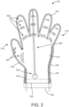
- FIGS. 3-5 various views of a first embodiment not in accordance with the claimed invention of the dressing 104 is shown.
- FIG. 3 shows a top view of the dressing 104 and
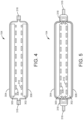
- FIGS. 4-6 show various cross-sectional views of the dressing 104.
- the dressing 104 is shown to include a first manifold layer 300, a second manifold layer 302, a first barrier layer 304 that is adjacent to (e.g., abuts) the first manifold layer 300, and a second barrier layer 306 abuts the second manifold layer 302.
- the first manifold layer 300 and the second manifold layer 302 are positioned between the first barrier layer 304 and the second barrier layer 306.
- the first manifold layer 300 is coupled to the first barrier layer 304 by an adhesive and/or the second manifold layer 302 is coupled to the second barrier layer 306 by an adhesive.
- the dressing 104 is also shown to includes a first fenestrated film layer 308 that abuts the first manifold layer 300 with and a second fenestrated film layer 310 that abuts the second manifold layer 302.
- the first manifold layer 300 is positioned between the first fenestrated film layer 308 and the first barrier layer 304
- the second manifold layer 302 is positioned between the second fenestrated film layer 310 and the second barrier layer 306.
- the first fenestrated film layer 308 is coupled to the first manifold layer 300 by an adhesive and/or the second fenestrated film layer 310 is coupled to the second manifold layer 302 by an adhesive. In preferred embodiments.
- the first fenestrated film layer 308 is configured to be easily separated from the second fenestrated film layer 310. That is, the first fenestrated film layer 308 and the second fenestrated film layer 310 are configured to not adhere to one another.
- each of the layers 302-310 includes a central region 312 and five peninsular projections 314 that extend from the central region 312 in the shape of a hand.
- Each of the five peninsular projections 314 corresponds to one finger or thumb of a patient.
- the dressing 104 may be made available in various sizes corresponding to different hand sizes (i.e., different dimensions of the central region 312 and the peninsular projections 314 of the layers 300-310). For example, the dressing 104 may be available in a small size, a medium size, a large size, etc. to allow fitting to various patients without requiring individual/patient-specific customization.
- the first barrier layer 304 is coupled to the second barrier layer 306 along a hand portion of a perimeter of the dressing 104 and separated from the second barrier layer 306 along a wrist portion 320 of the perimeter of the dressing 104.
- the first barrier layer 304 is not coupled to the second barrier layer 306 along the wrist portion 320 of the perimeter of the dressing 104, which creates an opening that allows a patient's hand to be inserted into the dressing 104.
- the dressing 104 is formed as a glove.
- the dressing 104 is thereby configured to receive a patient's hand between the first fenestrated film layer 308 and the second fenestrated film layer 310.
- the first barrier layer 304 is coupled to the second barrier layer 306 along edges of the peninsular regions 314 and the central region 312 by film welds 316, and along a portion of the perimeter of the central region by anchor welds 318.
- FIG. 4 shows a cross-section view of the dressing 104 including film welds 316.
- the film welds 316 couple the first barrier layer 304 to the second barrier layer 306 and substantially prevent air from passing between the first barrier layer 304 and the second barrier layer 306 at the film welds.
- the first barrier layer 304 may be thermally bonded to the second barrier layer 306 at the film welds 316.
- FIG. 5 shows a cross-section view of the dressing includes film welds 316 and anchor welds 318.
- the anchor welds 318 couple the first manifold layer, the second manifold layer 302, the first barrier layer 304, the second barrier layer 306, the first fenestrated film layer 308, and the second fenestrated film layer 310 together along portions of the perimeter of the dressing where the anchor welds 318 are present.
- the anchor welds 318 include structures (e.g., staples, pins, etc.) extending through the layers 300-310 to restrict (e.g., substantially prevent) movement of the layers 300-310 relative to one another at the anchor welds 318.
- adhesive is used along the anchor welds 318 to restrict movement of the layers 300-310 relative to one another at the anchor welds 318.
- the dressing 104 is also shown to include an adhesive cuff 322.
- Adhesive cuff 322 includes an adhesive (or multiple adhesives) configured to seal the adhesive cuff 322 to the first barrier layer 304 and the second barrier layer 306 along the wrist portion 320 of the perimeter of the dressing and to skin of a patient.
- the adhesive cuff 322 extends from the first barrier layer 304 and the second barrier layer 306 such that the adhesive cuff 322 is configured to be coupled to a wrist of a patient when the patient's hand is inserted into the dressing 104.
- the adhesive cuff 322 When the adhesive cuff 322 is sealed to a patient's wrist, the first barrier layer 304, and the second barrier layer 306, the adhesive cuff 322 substantially prevents air from flowing between an ambient environment and the interior of dressing 104 (e.g., the manifold layers 300, 302) via the opening at the wrist portion 320 of the dressing 104.
- the adhesive cuff 322 may be produced as an integrated piece of the dressing 104 or may be distributed as a separate piece of a dressing kit (e.g., as an adhesive strip).
- the barrier layers 304, 306 are configured to substantially prevent airflow therethrough.
- the barrier layers 304, 306 may include a polyurethane drape material, for example a drape material as used in a V.A.C. ® Drape by Acelity.
- the barrier layers 304, 306 are sealed with a substantially-airtight seal by film welds 316. Accordingly, when the adhesive cuff 322 is sealed around the wrist of a patient and the barrier layers 304, 306, a substantially airtight volume is created within the dressing 104, i.e., between the barrier layers 304, 306 and the patient's hand.
- the barrier layers 304, 306 may each have a thickness in a range between approximately 80 and 120 microns.
- the first barrier layer 304 includes knuckle flexion points 324 arranged at positions that correspond to knuckles/joints within a typical hand that may be inserted into the dressing 104.
- each peninsular portion 314 corresponding to a finger includes three knuckle flexion points 324, while the peninsular portion 314 corresponding to a thumb includes two knuckle flexion points.
- FIG. 6 shows cross sectional views of a knuckle flexion point 324, includes a first view 600 of the knuckle flexion point 324 in an unflexed state and a second view 602 of the knuckle flexion point 324. As illustrated by FIG.
- each knuckle flexion point 324 includes a series of folds (e.g., three folds) which, in the unflexed state, draw the barrier layer 304 away from the manifold layer 300.
- the series of folds are extended (unfolded) to facilitate curvature (bending) of the dressing 104 at the knuckle flexion point 324 by increasing an effective length of the barrier layer 304.
- the knuckle flexion points 324 are configured to facilitate articulation, movement, etc. of a patient's fingers confined in the dressing 104.
- the fenestrated film layers 308, 310 and the manifolding film layers 300, 302 may be configured to resiliently stretch and/or flex to accommodate articulation, movement, etc. of a hand in the dressing 104 as shown in FIG. 6 .
- the fenestrated film layers 308, 310 are made of a non-adherent film and are configured to provide a non-adherent interface between the dressing 104 and a hand of a patient, including a wound bed located on the hand.
- the fenestrated film layers 308, 310 are also configured to prevent ingrowth of skin to the dressing (e.g., healing into the manifold layers 300, 302).
- the fenestrated film layer 308, 310 thereby facilitate easy insertion of a hand into the dressing 104 and removal of the hand from the dressing 104.
- the fenestrated film layers 308, 310 have fenestrations (perforations, holes, airways, windows, etc.) extending therethrough that allow air and fluid to pass between the hand (e.g., a wound bed) and the manifold layers 300, 302.
- the fenestrated film layers 308 may each have a thickness of approximately 30 microns.
- the manifold layers 300, 302 are configured to allow air and fluid to flow therethrough.
- the manifold layers are made of an open-cell foam, for example a reticulated polyurethane open cell foam.
- the manifold layers 300, 302 are made of an open-cell foam marketed as GRANUFOAM TM by ACELITY TM .
- the manifold layers 300, 302 may each have a thickness in a range between approximately 6mm and 10mm. Accordingly, the manifold layers 300, 302 may be thinner than in conventional bulky dressings. The reduced thickness of the manifold layers 300, 302 facilitates flexion of the dressing 104 to allow for physiotherapy for the hand in the dressing 104 in a way not previously achieved.
- the manifold layers 300, 302 allow for the communication of air pressure, for example negative pressure (relative to ambient air pressure), through the manifold layers 300, 302 and to the hand and the wound bed (via the fenestrated film layers 308, 310.
- the dressing 104 is configured such that air and fluid can flow between the first manifold layer 300 and the second manifold layer 302 proximate the film welds 316 and anchor welds 318, i.e., through the fenestrated film layers 308, 310 and around a hand positioned in the dressing 104. Negative pressure can thereby be communicated across both manifold layers 300, 302 (i.e., such that both manifold layers 300, 302 are maintained at approximately equal pressures).
- the dressing 104 is configured to be coupled to a vacuum (negative pressure) tube 106 and, in some embodiments, an instillation tube 108.
- a hole may be cut in the first barrier layer 304 (e.g., with a diameter in a range between approximately 3-20mm) and a connection pad may be coupled to the barrier layer 304 over the hole.
- the connection pad is coupled to the vacuum tube 106 and/or instillation tube 108.
- multiple holes and/or connection pads are used.
- the connection pad may be a SENSAT.R.A.C. TM connection pad marketed by ACELITY TM .
- the manifold layers 300, 302 can thereby be put in fluid communication with the vacuum tube 106 and/or instillation tube 108.
- the negative pressure pump 112 can be controlled to remove air from the manifold layers 300, 302 to establish a negative pressure at the manifold layers 300, 302.
- the negative pressure at the manifold layers 300, 302 is communicated to the hand/wound via the fenestrations in the fenestrated film layers 308, 310.
- Instillation fluid may also be provided to the wound via the manifold layers 300, 302 and the fenestrated film layers 308. Wound exudate, instillation fluid, other debris, etc. may also be removed from the wound and manifold layers via the vacuum tube 106 as described above with reference to FIGS. 1-2 .
- the dressing 104 thereby facilitates treatment of a hand wound using NPWTi.
- the dressing 104 is also shown to include one or more sensor(s) 204. positioned on the first barrier layer 304.
- the one or more sensor(s) include a humidity sensor and a moisture sensor, which may be positioned extending through the first barrier layer 304 to measure humidity and moisture in the first manifold layer 300.
- the one or more sensor(s) include one or more pH sensor(s) configured to measure tissue pH and/or fluid pH.
- the one or more sensor(s) also include a strain sensor 326.
- the strain sensor 326 is positioned on or in the first barrier layer 304 and extends along a length of the dressing from proximate the wrist portion 320 to a tip of one of the peninsular regions 314 (e.g., corresponding to a middle finger).
- the strain sensor 326 is configured to measure (e.g., generate an electrical signal indicative of) a strain on the dressing 104 (i.e., on the strain sensor 326), which may correspond to a curvature of the dressing 104 and/or a force applied by the hand inside the dressing 104.
- a strain measured by the strain sensor 326 may increase when a patient attempts to clench the hand (e.g., in a fist) or otherwise bend one or more fingers in the dressing 104.
- the strain may decrease when the patient moves the hand in the dressing 104 to an open or neutral pose.
- the one or more sensors 204 include a wireless communications circuit (e.g., WiFi transceiver, Bluetooth transceiver, etc.) configured to facilitate wireless transmission of measurements from the one or more sensors to the control circuit 202 of the therapy unit 102.
- a wireless communications circuit e.g., WiFi transceiver, Bluetooth transceiver, etc.
- FIGS. 7-9 a second embodiment also not in accordance with the claimed invention of the dressing 104 is shown, according to an exemplary embodiment.
- the non-adhesive fenestrated film layers 308, 310 are omitted from the dressing 104, such that the dressing 104 is formed as a glove including the barrier layers 304, 306 and the manifold layers 300, 302 arranged as described above.
- a wound-dressing interface 700 is also included as a separate piece (i.e., distributed to caregivers/patients as a separate piece in a dressing kit that also includes the glove-shaped dressing 104 formed from the barrier layers 304, 306 and the manifold layers 300, 302).
- the wound-dressing interface 700 is formed as a single piece (sheet) as shown in FIG. 4 , for example shaped within peninsular extensions and or bridge/isthmus-shaped portions configured to be aligned with fingers of a patient when the wound-dressing interface 700 is folded over a patient's hand.
- the wound-dressing interface 700 includes a patient interface layer 702 and a foam interface layer 704.
- the foam interface layer 704 includes a fenestrated film, for example a polyurethane or polyethylene film with fenestrations extending therethrough.
- the foam interface layer 704 allows air and fluid to flow therethrough and limits adherence of the wound-dressing interface 700 to the manifold layers 300, 302.
- the patient interface layer 702 includes a perforated silicone and a hydrogel or polyurethane gel.
- the patient interface layer 702 is configured to adhere to itself. In some embodiments, the patient interface layer 702 is configured to adhere to skin.
- the wound-dressing interface 700 is thereby configured to be folded over a hand and adhered to itself (mated to itself) to substantially enclose the hand in the wound dressing interface 700 such that the patient interface layer 702 faces inwards (i.e., towards the hand) and the foam interface layer 704 faces outwards (i.e., away from the hand).
- the hand and the wound-dressing interface 700 can then be inserted into the glove portion of the dressing 104, i.e., the barrier layers 304, 306 and the manifold layers 300, 302 arranged as described above (and as shown in FIGS. 9 and 3 ).
- the wound-dressing interface 700 prevents direct contact between the hand and the manifold layers 300, 302 while allowing air and fluid to pass through fenestrations in the wound-dressing interface 700.
- the adhesive cuff 322 can then be applied around the patient's wrist to seal the dressing 104 around the hand as described above.
- a hole can be cut in a barrier layer 304, 306 and a connection pad coupled to the barrier layer 304, 306 over the hole to place a vacuum tube 106 and/or an instillation tube 108 in fluid communication with the manifold layers 300, 302.
- the therapy unit 102 can then be operated as described above to establish negative pressure at the hand and/or provide instillation fluid to the hand.
- FIGS. 3-9 show glove-shaped dressings, i.e., with individually-differentiated fingers (e.g., as formed by peninsular projections 314).
- Other embodiments of the dressing 104 may be mitten-shaped, i.e., with a unified area for four fingers and a separate projection for a thumb.
- Such mitten-shaped dressings may otherwise be configured as described herein for the glove-shaped dressings of FIGS. 3-9 .
- Other variations are also contemplated by the presented disclosure, for example a three-compartment glove where the two pairs of fingers each share a compartment and the thumb has a compartment, etc. All such variations are within the scope of the present disclosure.
- Process 1000 provides a physiotherapy mode that allows movement, articulation, bending, etc. of a hand in the dressing 104 during NPWTi treatment. Accordingly, execution of process 1000 facilitates a patient in redeveloping strength, neuromuscular activity, coordination, etc. in the hand while the dressing 104 is applied to the hand.
- Process 1000 can be executed by the control circuit 202 of the therapy unit 102.
- the negative pressure pump 112 is operated to establish a first level of negative pressure at the glove-shaped dressing 104.
- the first level of negative pressure may correspond to a preferred level for negative pressure wound therapy, for example in the range of approximately 100 mmHg to 175 mmHg of negative pressure.
- the pressure differential between the ambient air and the interior of the dressing 104 increases the rigidity of the dressing 104 such that dressing 104 substantially restricts (limits, prevents, etc.) articulation of the hand.
- a measurement is received from the strain sensor 326 on the glove-shaped dressing 104.
- the measurement includes a current value of a strain on the dressing 104.
- the strain on the dressing 104 may correspond to an amount of force exerted on the dressing 104 by the hand in the dressing 104 in an attempt to curl, bend, articulate, etc. the fingers in the dressing 104.
- the measurement may be received by the control circuit 202 via a wireless network (e.g., Bluetooth communications, WiFi communications, etc.).
- the measurement is compared to a threshold strain value.
- the threshold strain value may be predetermined, for example by bench testing.
- the threshold strain value corresponds to a significant probability that the patient is deliberately attempting to articulate the hand in the dressing 104.
- pump 112 continues to be controlled to provide the first level of negative pressure at the dressing 104 while more measurements of the strain are received at the control circuit 202 over time.
- a physiotherapy mode is initiated at step 1008.
- the pump 112 is controlled (e.g., by the control circuit 202) to reduce the negative pressure from the first level of negative pressure to a second level of negative pressure.
- the second level of negative pressure is "lower" than the first level of negative pressure, i.e., closer to atmospheric pressure (e.g., in a range of approximately 25mmHg to 75 mmHg).
- the rigidity of the dressing 104 is lower than at the first level of negative pressure.
- the dressing 104 and the NPWIT system 100 allows the patient to at least partially bend, articulate, move, etc. the fingers and hand in the dressing 104.
- the patient may follow guided instructions from a therapist.
- the therapy unit is configured to provide instructions for a physiotherapy routine to a user via the input/output device 118.
- step 1010 additional measurements of the strain are received from the strain sensor 234. As the patient continues to articulate the hand in the dressing 104, the strain will stay above the threshold strain value and/or repeatedly exceed the threshold strain value.
- step 1012 a determination is made of whether the measurement has fallen below the threshold strain value for at least a threshold duration of time. The threshold duration of time may be selected as indicative that the patient has ended a physiotherapy routine or other attempt to articulate the hand in the dressing 104. If the strain has not fallen below the threshold strain value for at least the threshold duration of time, the pump 112 continues to be controlled to maintain the second level of negative pressure at the dressing.
- the pump 112 is controlled to reestablish the first level of negative pressure at the dressing at step 1014, i.e., to reestablish an optimal NPWTi regime and exit the physiotherapy mode.
- the process may then return to step 1004 where the strain measurements are monitored. Repeated iterations of the physiotherapy mode may thereby be initiated and exited to facilitate both physiotherapy and NPWTi for the hand in the dressing 104 over time.
- the dressing 104 may be well-suited for long-term application to the hand (e.g., seven days or longer).
- the physiotherapy mode can be initiated or ended in response to user input to the input/output device 118 commanding a start or end to the physiotherapy mode.
- the control circuit 202 may prevent execution of the process 1000 (e.g., prevent initiation of physiotherapy mode) during an instillation cycle (e.g., while instillation fluid is being supplied to the dressing 104).
- a dynamic pressure control mode e.g., cyclic variations in negative pressure
- is applied outside of the physiotherapy mode e.g., in place of the first level of negative pressure.
- a variation suitable for use on a foot may be formed as a sock, with or without a separate pocket/projection for each toe, rather than as a glove as shown for the hand dressings described above.
- Variations of the dressing 104 can therefore be tailored for use in treating wounds in many anatomical locations.
- the dressing 104 and NPWTi system 100 described above provide various advantages over existing dressings and wound therapy systems.
- the dressing 104 is easy to apply (thereby reducing application time) and remove without damaging the healed/healing wound (e.g., by avoiding a risk of in-growth into the dressing structure).
- the dressing 104 and NPWTi system 100 also allow for effective positioning of the dressing 104 while also allowing early movement in the full range of motion (or at least a significant portion of the range of motion) of the wounded/treated hand.
- the dressing 104 and NPWTi system 100 in the embodiments shown, are suitable for providing negative pressure and instillation therapy for up to at least seven days.
- the dressing 104 may reduce the use of foam relative to existing dressings, thereby making the dressing 104 smaller and less cumbersome for the patient.
- the dressing 104 and the NPWTi system 100 in the embodiments shown, also provide for an automatic physiotherapy mode that facilitates rehabilitation and reduces the risk of contractures.
- the dressing 104 includes sensors that wirelessly (e.g., without the annoyance/complication of additional cables/wires/etc.) communicate useful measurements/diagnostics to a caregiver that allow early detection of infection or other developments in wound treatment. Therefore, the dressing 104 and NPWTi system 100 disclosed herein provide many advantages over existing systems that can improve outcomes for patients while also improving the overall treatment experience.
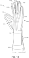
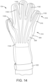
- FIGS. 11-16 another embodiment of the dressing 104 is shown, according to exemplary embodiments.
- FIGS. 11-14 show various perspective views of the dressing 104.
- FIG. 15 shows a cross-sectional view of the dressing 104.
- FIG. 16 illustrates an advantageous behavior of the dressing 104 when air is removed from the dressing 104.
- the dressing 104 as in FIGS. 11-16 may include some or all of the various features and advantages of the dressing 104 in the embodiments described above, with some differences as described in detail below.
- the dressing 104 includes transparent or translucent portions such that a patient or caregiver can visually assess a wound without removing the dressing 104 from the patient's hand.
- the manifold layers 300, 302 are formed as multiple felted foam strips 1100 which extend from a felted foam pad 1102.
- Each felted foam strip extends from the central region 312 of the dressing to one of the multiple peninsular projections 314.
- each "finger" (including the "thumb") of the dressing 104 has a corresponding felted foam strip 1100 aligned therewith.
- both a first side 1110 of the dressing 104 (corresponding to a back of the hand) and a second side 1112 of the dressing 104 (corresponding to the palm of the hand) include felted foam strips 1100.
- two felted foam strips 1100 are aligned with each of the peninsular projections 314 (i.e., one felted foam strip 100 on the first side 1110 and one felted foam strip 1100 on the second side 1112). It should be understood that various arrangements, numbers, patterns, webs, lattices, etc. of felted foam strips 1100 are possible in various embodiments.
- the felted foam pad 1102 includes a wrist strap 1104 and a connection surface 1106.
- the wrist strap 1104 e.g., felted foam cuff
- the wrist strap 1104 is located at a wrist region of the dressing 104 and connects the felted foam strips 1100 of the first side 1110 with the felted foam strips 1100 of the second side 1112, thereby allowing air and fluid to flow between the felted foam strips 1100 of the first side 1110 and the felted foam strips 1100 of the second side (e.g., to facilitate communication of negative pressure between the first side 1110 and the second side 1112).
- connection surface 1106 provides an area of felted foam having a sufficient surface area to allow connection of the dressing 104 to the tube 106 in fluid communication with the manifolding layer 300 (i.e., with the wrist strap 1104 and the felted foam strips 1100).
- the felted foam strips 1100 and the wrist strap 1104 may be narrow (e.g., having a width less than a diameter of a connection pad 1108 which couples the dressing 104 to the vacuum tube 106 and, in some embodiments, to the instillation tube 108.
- connection surface 1106 provides a larger surface area (e.g., having a diameter equal to or larger than the diameter of the connection pad 1108; having a diameter in a range between approximately ten millimeters and approximate twenty-five millimeters, for example approximately twenty millimeters; etc.) which allows the tube 106 to be placed in fluid communication with the manifolding layer 300.
- the connection surface 1106 of the felted foam pad 1102 is located along a forearm region of the dressing 104, such that the connection pad 1108 is positioned at a non-articulating anatomical feature when applied to a patient.
- the connection surface 1106 thereby provides a convenient, comfortable, and effective position at which the connection pad 1108 can be coupled to the dressing 104.
- the dressing 104 includes as a first manifold layer 300 (shown as a felted foam strip 1100), a second manifold layer 302 (also shown as a felted foam strip 1100), a first barrier film layer 304, a second barrier film layer 306, a first fenestrated film layer (wound contact layer) 308, and a second fenestrated film layer (wound contact layer) 308.
- the first manifold layer 300 is positioned between the first fenestrated film layer 308 and the first barrier layer 304
- the second manifold layer 302 is positioned between the second fenestrated film layer 310 and the second barrier layer 306.
- the first manifold layer 300, the first fenestrated film layer 308, and the first barrier film layer 304 form a first side 1110 of the dressing 104.
- the second manifold layer 302, the second fenestrated film layer 310, and the second barrier layer 306 form a second side of the dressing 104.
- the first side 1110 and/or the second side 1112 are thermoformed to have a domed cross section to match the anatomical curvature of a hand, thereby improving fit, aesthetics, and comfort of the dressing 104.
- the first manifold layer 300 and second manifold layer 302 are formed as felted foam strips 1100 that occupy only a portion (i.e., less than an entirety) of the surface area of the barrier film layers 304, 306 and only a portion (i.e., less than an entirety) of the surface area of the fenestrated film layers 308, 310.
- the felted foam strips 1100 may have a width in a range of approximately two millimeters to ten millimeters, and may have a thickness in a range of approximately one millimeter to two millimeters.
- the first barrier film layer 304 is adjacent to (e.g., abutting) the first fenestrated film layer 308 and the second barrier film layer 306 is adjacent to the second fenestrated film layer 310.
- the barrier film layers 304, 306 and the fenestrated film layers 308 are transparent or translucent.
- the dressing 104 can be transparent or translucent. Accordingly, in the embodiments of FIGS. 11-16 , the dressing 104 is configured to allow a patient or caregiver to visually assess (see, optically inspect, etc.) a wound through the dressing 104 without removal or modification of the dressing 104. The dressing 104 thereby facilitates a caregiver or patient in monitoring wound healing and, in some cases, making adjustments to wound therapy based on such monitoring.
- the first side 1110 and the second side 1112 may be coupled together by welds 316 and/or 318 around a perimeter of the dressing 104 with the exception of an opening at a wrist portion 320 of the perimeter of the dressing 104 (e.g., as described above with reference to FIGS. 3-5 ).
- spot welds 1600 may also be included and distributed between and around the felted foam strips 1100.
- the first barrier film layer 304 is coupled (e.g., welded, adhered) to the first fenestrated film layer 308.
- the second barrier film layer 306 is coupled to the second fenestrated film layer 310.
- the spot welds 1600 may be placed to partially constrain movement of the of the felted foam strips 1100.
- spot welds 1600 may be placed slightly apart from the felted foam strips 1100 such that the felted foam strips 1100 are allowed to move, bend, translate, slide, etc. within a limited range of positions relative to the barrier film layer 304/306 and the fenestrated film layer 308/310.
- the spot welds 1600 ensure that the felted foam strips 1100 remain substantially aligned with the peninsular (finger, thumb) regions 314 while allowing for some movement and repositioning which facilitates the dressing 104 in conforming to a particular patient's hand, provides flexibility to the dressing 104, and facilitates articulation of the patient's hand while the dressing 104 is applied to the hand.
- an adhesive can be included to couplet the felted foam strips 1100 to the barrier film layer 304/306 and/or the fenestrated film layer 308/310.
- FIG. 16 illustrates application and use of the dressing 104 of FIGS. 11-15 in a two-frame storyboard depiction.
- the dressing 104 is placed onto a patient's hand and the adhesive cuff 322 is applied to seal the dressing 104 around the patient's wrist or forearm.
- the dressing 104 may include a wrist/forearm region of various lengths (i.e., to extend along a forearm of a patient), such that the opening may align with various locations on the forearm of the patent in various embodiments.
- the dressing 104 may be sized slightly larger than the hand to facilitate insertion of the hand into the dressing 104.
- the negative pressure pump 112 is operated to remove air and/or other fluids or debris from the dressing 104 via the tube 106, the connection pad 1108, the felted foam pad 1102, and the felted foam strips 1100 to establish a negative pressure within the dressing 104 and at the hand (e.g., at a wound).
- Operating the negative pressure pump 112 results in a reduction in volume of the dressing 104 as the dressing 104 is pulled inwards towards the hand by the pressure differential across the barrier film layers 304, 306.
- the reduction in volume of the dressing 104 in response to operation of the negative pressure pump 112 results in the formation of wrinkles (creases, folds, etc.) in the barrier film layers 304, 306 and the fenestrated film layers 308, 310.
- the wrinkles may form with openings, gaps, channels, airways, etc. in and across the wrinkles, such that at least a portion of the wrinkles provide manifolding pathways for air and fluid flow.
- gaps, channels, etc. may be formed between the barrier film layers 304, 306 and the fenestrated film layers 308, 310.
- at least a portion of the wrinkles are in fluid and/or pneumatic communication with the felted film strips 1100. Accordingly, air and fluid can flow between the felted film strips 1100 and regions of the hand not directly aligned with the felted foam strips 1100.
- the felted foam strips 1100 cover only a portion of the surface area of the dressing 104 and the hand treated thereby, the wrinkles formed by operation negative pressure pump 112 can provide air and fluid manifolding to a much larger portion of the surface area of the dressing 104 and the hand (e.g., to the substantially the entire hand).
- the dressing 104 thereby facilitates the establishment and maintenance of a negative pressure at the hand, removal of wound exudate and other fluid/debris from the hand, and, in some embodiments, instillation of an instillation fluid to the hand.
- the (substantially opaque) felted foam material covers only a portion of the surface area of the dressing 104, a patient or caregiver can visually inspect a wound without removing the dressing 104, including while negative pressure is established at the hand.
- thermo-chromic indicators are positioned on the fenestrated film layers 308, 310, for example on the inner (i.e., hand-facing) surface or outer (i.e., non-hand-facing) surface of the fenestrated film layers 308, 310.
- the thermo-chromic indicators are configured to change color with changes in temperature, such that the color of a thermo-chromic indictor is indicative of the temperature of the skin or wound bed proximate the thermo-chromic indicator. Because the dressing 104 of FIGS. 11-16 is translucent or transparent in various regions, such indicators may be visible through the dressing 104, thereby allowing a patient or caregiver to assess wound healing on the basis of temperature indications.
- Such temperature indicators may be particularly useful in assessment and treatment of burns. Multiple indicators can be used to provide temperature information at multiple locations of the dressing 104.
- pH-chromic indicators configured to change color with changes in pH may be included with the dressing 104 and opinionated like the thermo-chromic indicators to provide information relating to the pH of the hand at various areas of the hand.
- the felted foam strips 1100 are non-felted. That is, the foam strips 1100 may be made of an open-celled polyurethane foam which may or may not be felted (e.g., heated and compressed) in various embodiments. In other embodiments, the felted foam strips 1100 are replaced by non-foam thermoformed pathways, for example tubes or other pathways formed on or coupled to the barrier film layer (e.g., formed of a polyurethane drape material). In other embodiments, various spacer materials are positioned to cause the wrinkles to form in a desired pattern, in some cases such that some or all of the felted foam strips 1100 can be omitted.
- the first side 1110 of the dressing 104 includes the felted foam strips as in FIGS. 11-16
- the second side 1112 includes a sold/continuous manifold layer 302 as in FIGS. 3-5 (or vice versa).
- felted foam materials, strips, pads, zones, etc. may be used to customize wound therapy. All such variations are within the scope of the present disclosure.
Landscapes
- Health & Medical Sciences (AREA)
- Heart & Thoracic Surgery (AREA)
- General Health & Medical Sciences (AREA)
- Engineering & Computer Science (AREA)
- Biomedical Technology (AREA)
- Life Sciences & Earth Sciences (AREA)
- Animal Behavior & Ethology (AREA)
- Vascular Medicine (AREA)
- Public Health (AREA)
- Veterinary Medicine (AREA)
- Anesthesiology (AREA)
- Hematology (AREA)
- Pulmonology (AREA)
- Media Introduction/Drainage Providing Device (AREA)
Claims (17)
- Pansement (104) pour thérapie de plaie par pression négative, comprenant :une couche de film barrière (304) ;une couche de contact de la plaie (308) accouplée à la couche de film barrière (304) ; etune pluralité de bandes de mousse feutrée (1100) positionnées entre la couche de film barrière (304) et la couche de contact avec la plaie (308), chaque bande fournissant une voie de pliage ;dans lequel la couche de film barrière (304) et la couche de contact avec la plaie (308) comprennent une région centrale (312) et une pluralité de projections péninsulaires (314) s'étendant à partir de celle-ci sous la forme d'une main ; etdans lequel la pluralité de bandes de mousse feutrée (1100) n'occupe qu'une partie de la surface de la couche de film barrière (304) et qu'une partie de la surface de la couche de contact avec la plaie (308).
- Pansement (104) selon la revendication 1, dans lequel chaque bande s'étend à partir de la région centrale (312) jusqu'à l'une de la pluralité de projections péninsulaires (314).
- Pansement (104) selon la revendication 2, comprenant un tampon de mousse feutrée (1102) positionné au niveau de la région centrale (312), la pluralité de bandes s'étendant à partir du tampon de mousse feutrée (1102).
- Pansement (104) selon la revendication 3, comprenant un ensemble de liaison accouplé à la couche de film barrière (304) au niveau du tampon de mousse feutrée (1102), l'ensemble de liaison conçu pour fournir un écoulement d'air entre le tampon de mousse feutrée (1102) et un tube (106) accouplé à l'ensemble de liaison.
- Pansement (104) selon la revendication 3, dans lequel la pluralité de bandes de mousse feutrée (1100) sont conçues pour permettre un écoulement d'air entre les régions péninsulaires et le tampon de mousse feutrée (1102), éventuellement dans lequel :la couche de film barrière (304) et la couche de contact avec la plaie (308) sont conçues pour former des plis dans celles-ci lorsque l'air est évacué du pansement (104) par les bandes de mousse feutrée (1100) ; etles plis permettent au fluide de s'écouler à travers ceux-ci.
- Pansement (104) selon la revendication 1, dans lequel les bandes de mousse feutrée (1100) comprennent une mousse à cellules ouvertes.
- Pansement (104) selon la revendication 1, dans lequel la couche de contact avec la plaie (308) et la couche de film barrière (304) sont conçues pour permettre une observation visuelle d'une plaie à travers la couche de contact avec la plaie (308) et la couche de film barrière (304).
- Pansement (104) selon la revendication 1, dans lequel :la couche de film barrière (304) est soudée à la couche de contact avec la plaie (308) autour d'un périmètre de la couche de film barrière (304) et au niveau d'une pluralité de soudures par points (1600) réparties parmi la pluralité de bandes de mousse feutrée (1100) ; etles soudures par points (1600) limitent le mouvement de la pluralité de bandes de mousse feutrée (1100) par rapport à la couche de film barrière (304) et à la couche de contact avec la plaie (308).
- Pansement (104) selon la revendication 1, dans lequel :la couche de film barrière (304), la couche de contact avec la plaie (308) et la pluralité de bandes de mousse feutrée (1100) sont formées comme un premier côté d'un ensemble gant ; etle premier côté de l'ensemble gant est accouplé à un second côté de l'ensemble gant pour former l'ensemble gant.
- Pansement (104) selon la revendication 10, dans lequel le deuxième côté de l'ensemble gant comprend :une seconde couche de film barrière (306) ;une seconde couche de contact avec la plaie (310) accouplée à la seconde couche de film barrière (306) ; etune pluralité de secondes bandes de mousse feutrée (1100) positionnées entre la couche de film barrière (304) et la couche de contact avec la plaie (308), chaque bande fournissant une voie de pliage.
- Pansement (104) selon la revendication 11, comprenant une manchette de mousse feutrée pouvant communiquer fluidiquement avec la pluralité de bandes de mousse feutrée (1100) du premier côté et la pluralité de secondes bandes de mousse feutrée (1100) du second côté.
- Pansement (104) selon la revendication 11, dans lequel l'ensemble gant est conçu pour recevoir une main d'un patient entre la couche de contact avec la plaie (308) et la seconde couche de contact avec la plaie (310), comprenant éventuellement un adhésif conçu pour sceller le premier côté et le second côté à un poignet du patient lorsque l'ensemble gant reçoit la main ;
dans lequel la couche de film barrière (304) et la seconde couche de film barrière (306) fournissent un volume sensiblement étanche à l'air entre elles lorsque l'adhésif est scellé sur le poignet du patient. - Système de thérapie de plaie, comprenant :une pompe (112) ;un tube (106) accouplé à la pompe (112) ;un pansement (104) selon l'une quelconque revendication précédente accouplé au tube (106).
- Système de thérapie de plaie selon la revendication 13, dans lequel les bandes de mousse feutrée (1100) peuvent communiquer fluidiquement avec la pompe (112) par l'intermédiaire du tube (106), la pompe (112) étant conçue pour extraire une pression négative sur les bandes de mousse feutrée (1100).
- Système de thérapie de plaie selon la revendication 14, dans lequel la couche de film barrière (304) et la couche de contact avec la plaie (308) sont conçues pour former des plis lorsque la pompe (112) extrait la pression négative sur les bandes de mousse feutrée (1100).
- Système de thérapie de plaie selon la revendication 15, dans lequel les plis permettent un écoulement d'air à travers ceux-ci.
- Système de thérapie de plaie selon la revendication 13, comprenant un tampon de mousse feutrée (1102) positionné dans la région centrale (312), dans lequel :la pluralité de bandes de mousse feutrée (1100) s'étendent à partir du tampon de mousse feutrée (1102) ; etle tube (106) est accouplé au pansement (104) à proximité du tampon de mousse feutrée (1102).
Applications Claiming Priority (2)
| Application Number | Priority Date | Filing Date | Title |
|---|---|---|---|
| US201962881591P | 2019-08-01 | 2019-08-01 | |
| PCT/IB2020/057197 WO2021019486A1 (fr) | 2019-08-01 | 2020-07-30 | Pansement pour main destiné à être utilisé lors d'une thérapie de plaies par pression négative |
Publications (2)
| Publication Number | Publication Date |
|---|---|
| EP4007552A1 EP4007552A1 (fr) | 2022-06-08 |
| EP4007552B1 true EP4007552B1 (fr) | 2025-03-19 |
Family
ID=71948649
Family Applications (1)
| Application Number | Title | Priority Date | Filing Date |
|---|---|---|---|
| EP20751310.2A Active EP4007552B1 (fr) | 2019-08-01 | 2020-07-30 | Pansement pour main destiné à être utilisé lors d'une thérapie de plaies par pression négative |
Country Status (3)
| Country | Link |
|---|---|
| US (1) | US12343239B2 (fr) |
| EP (1) | EP4007552B1 (fr) |
| WO (1) | WO2021019486A1 (fr) |
Families Citing this family (4)
| Publication number | Priority date | Publication date | Assignee | Title |
|---|---|---|---|---|
| AU2017243601A1 (en) | 2016-03-30 | 2018-11-22 | Acib Gmbh | Detecting microbial infection in wounds |
| SG11202112292QA (en) | 2019-06-03 | 2021-12-30 | Convatec Ltd | Methods and devices to disrupt and contain pathogens |
| EP4081128A1 (fr) | 2019-12-23 | 2022-11-02 | ConvaTec Limited | Dispositifs de point de soins pour détecter l'état d'infection d'une plaie |
| TWI820881B (zh) * | 2022-08-26 | 2023-11-01 | 南臺學校財團法人南臺科技大學 | 居家輔助手套 |
Family Cites Families (144)
| Publication number | Priority date | Publication date | Assignee | Title |
|---|---|---|---|---|
| US1355846A (en) | 1920-02-06 | 1920-10-19 | David A Rannells | Medical appliance |
| US2547758A (en) | 1949-01-05 | 1951-04-03 | Wilmer B Keeling | Instrument for treating the male urethra |
| US2632443A (en) | 1949-04-18 | 1953-03-24 | Eleanor P Lesher | Surgical dressing |
| GB692578A (en) | 1949-09-13 | 1953-06-10 | Minnesota Mining & Mfg | Improvements in or relating to drape sheets for surgical use |
| US2682873A (en) | 1952-07-30 | 1954-07-06 | Johnson & Johnson | General purpose protective dressing |
| NL189176B (nl) | 1956-07-13 | 1900-01-01 | Hisamitsu Pharmaceutical Co | Pleister op basis van een synthetische rubber. |
| US2969057A (en) | 1957-11-04 | 1961-01-24 | Brady Co W H | Nematodic swab |
| US3066672A (en) | 1960-09-27 | 1962-12-04 | Jr William H Crosby | Method and apparatus for serial sampling of intestinal juice |
| US3367332A (en) | 1965-08-27 | 1968-02-06 | Gen Electric | Product and process for establishing a sterile area of skin |
| US3520300A (en) | 1967-03-15 | 1970-07-14 | Amp Inc | Surgical sponge and suction device |
| US3568675A (en) | 1968-08-30 | 1971-03-09 | Clyde B Harvey | Fistula and penetrating wound dressing |
| US3682180A (en) | 1970-06-08 | 1972-08-08 | Coilform Co Inc | Drain clip for surgical drain |
| BE789293Q (fr) | 1970-12-07 | 1973-01-15 | Parke Davis & Co | Pansement medico-chirugical pour brulures et lesions analogues |
| US3826254A (en) | 1973-02-26 | 1974-07-30 | Verco Ind | Needle or catheter retaining appliance |
| DE2527706A1 (de) | 1975-06-21 | 1976-12-30 | Hanfried Dr Med Weigand | Einrichtung zum einleiten von kontrastmittel in einen kuenstlichen darmausgang |
| DE2640413C3 (de) | 1976-09-08 | 1980-03-27 | Richard Wolf Gmbh, 7134 Knittlingen | Katheter-Überwachungsgerät |
| NL7710909A (nl) | 1976-10-08 | 1978-04-11 | Smith & Nephew | Samengestelde hechtstrook. |
| GB1562244A (en) | 1976-11-11 | 1980-03-05 | Lock P M | Wound dressing materials |
| US4080970A (en) | 1976-11-17 | 1978-03-28 | Miller Thomas J | Post-operative combination dressing and internal drain tube with external shield and tube connector |
| US4139004A (en) | 1977-02-17 | 1979-02-13 | Gonzalez Jr Harry | Bandage apparatus for treating burns |
| US4184510A (en) | 1977-03-15 | 1980-01-22 | Fibra-Sonics, Inc. | Valued device for controlling vacuum in surgery |
| US4165748A (en) | 1977-11-07 | 1979-08-28 | Johnson Melissa C | Catheter tube holder |
| US4256109A (en) | 1978-07-10 | 1981-03-17 | Nichols Robert L | Shut off valve for medical suction apparatus |
| SE414994B (sv) | 1978-11-28 | 1980-09-01 | Landstingens Inkopscentral | Venkateterforband |
| WO1980001139A1 (fr) | 1978-12-06 | 1980-06-12 | Svedman Paul | Dispositif de traitement des tissus, par exemple de la peau |
| US4266545A (en) | 1979-04-06 | 1981-05-12 | Moss James P | Portable suction device for collecting fluids from a closed wound |
| US4284079A (en) | 1979-06-28 | 1981-08-18 | Adair Edwin Lloyd | Method for applying a male incontinence device |
| US4261363A (en) | 1979-11-09 | 1981-04-14 | C. R. Bard, Inc. | Retention clips for body fluid drains |
| US4569348A (en) | 1980-02-22 | 1986-02-11 | Velcro Usa Inc. | Catheter tube holder strap |
| ATE14835T1 (de) | 1980-03-11 | 1985-08-15 | Schmid Eduard | Hauttransplantations-druckverband. |
| US4297995A (en) | 1980-06-03 | 1981-11-03 | Key Pharmaceuticals, Inc. | Bandage containing attachment post |
| US4333468A (en) | 1980-08-18 | 1982-06-08 | Geist Robert W | Mesentery tube holder apparatus |
| US4465485A (en) | 1981-03-06 | 1984-08-14 | Becton, Dickinson And Company | Suction canister with unitary shut-off valve and filter features |
| US4392853A (en) | 1981-03-16 | 1983-07-12 | Rudolph Muto | Sterile assembly for protecting and fastening an indwelling device |
| US4373519A (en) | 1981-06-26 | 1983-02-15 | Minnesota Mining And Manufacturing Company | Composite wound dressing |
| US4392858A (en) | 1981-07-16 | 1983-07-12 | Sherwood Medical Company | Wound drainage device |
| US4419097A (en) | 1981-07-31 | 1983-12-06 | Rexar Industries, Inc. | Attachment for catheter tube |
| AU550575B2 (en) | 1981-08-07 | 1986-03-27 | Richard Christian Wright | Wound drainage device |
| SE429197B (sv) | 1981-10-14 | 1983-08-22 | Frese Nielsen | Anordning for behandling av sar |
| DE3146266A1 (de) | 1981-11-21 | 1983-06-01 | B. Braun Melsungen Ag, 3508 Melsungen | Kombinierte vorrichtung fuer eine medizinische saugdrainage |
| US4551139A (en) | 1982-02-08 | 1985-11-05 | Marion Laboratories, Inc. | Method and apparatus for burn wound treatment |
| US4475909A (en) | 1982-05-06 | 1984-10-09 | Eisenberg Melvin I | Male urinary device and method for applying the device |
| EP0100148B1 (fr) | 1982-07-06 | 1986-01-08 | Dow Corning Limited | Pansement médico-chirurgical et son procédé de production |
| NZ206837A (en) | 1983-01-27 | 1986-08-08 | Johnson & Johnson Prod Inc | Thin film adhesive dressing:backing material in three sections |
| US4548202A (en) | 1983-06-20 | 1985-10-22 | Ethicon, Inc. | Mesh tissue fasteners |
| US4540412A (en) | 1983-07-14 | 1985-09-10 | The Kendall Company | Device for moist heat therapy |
| US4543100A (en) | 1983-11-01 | 1985-09-24 | Brodsky Stuart A | Catheter and drain tube retainer |
| US4525374A (en) | 1984-02-27 | 1985-06-25 | Manresa, Inc. | Treating hydrophobic filters to render them hydrophilic |
| CA1286177C (fr) | 1984-05-03 | 1991-07-16 | Smith And Nephew Associated Companies Plc | Pansement adhesif |
| US4897081A (en) | 1984-05-25 | 1990-01-30 | Thermedics Inc. | Percutaneous access device |
| US5215522A (en) | 1984-07-23 | 1993-06-01 | Ballard Medical Products | Single use medical aspirating device and method |
| GB8419745D0 (en) | 1984-08-02 | 1984-09-05 | Smith & Nephew Ass | Wound dressing |
| US4872450A (en) | 1984-08-17 | 1989-10-10 | Austad Eric D | Wound dressing and method of forming same |
| US4826494A (en) | 1984-11-09 | 1989-05-02 | Stryker Corporation | Vacuum wound drainage system |
| US4655754A (en) | 1984-11-09 | 1987-04-07 | Stryker Corporation | Vacuum wound drainage system and lipids baffle therefor |
| US4605399A (en) | 1984-12-04 | 1986-08-12 | Complex, Inc. | Transdermal infusion device |
| US5037397A (en) | 1985-05-03 | 1991-08-06 | Medical Distributors, Inc. | Universal clamp |
| US4640688A (en) | 1985-08-23 | 1987-02-03 | Mentor Corporation | Urine collection catheter |
| US4710165A (en) | 1985-09-16 | 1987-12-01 | Mcneil Charles B | Wearable, variable rate suction/collection device |
| US4758220A (en) | 1985-09-26 | 1988-07-19 | Alcon Laboratories, Inc. | Surgical cassette proximity sensing and latching apparatus |
| US4733659A (en) | 1986-01-17 | 1988-03-29 | Seton Company | Foam bandage |
| WO1987004626A1 (fr) | 1986-01-31 | 1987-08-13 | Osmond, Roger, L., W. | Systeme de succion pour drainage de blessures et drainage gastro-intestinal |
| US4838883A (en) | 1986-03-07 | 1989-06-13 | Nissho Corporation | Urine-collecting device |
| JPS62281965A (ja) | 1986-05-29 | 1987-12-07 | テルモ株式会社 | カテ−テルおよびカテ−テル用固定部材 |
| GB8621884D0 (en) | 1986-09-11 | 1986-10-15 | Bard Ltd | Catheter applicator |
| GB2195255B (en) | 1986-09-30 | 1991-05-01 | Vacutec Uk Limited | Apparatus for vacuum treatment of an epidermal surface |
| US4743232A (en) | 1986-10-06 | 1988-05-10 | The Clinipad Corporation | Package assembly for plastic film bandage |
| DE3634569A1 (de) | 1986-10-10 | 1988-04-21 | Sachse Hans E | Kondomkatheter, ein harnroehrenkatheter zur verhinderung von aufsteigenden infektionen |
| JPS63135179A (ja) | 1986-11-26 | 1988-06-07 | 立花 俊郎 | 薬物の経皮投与具 |
| GB8628564D0 (en) | 1986-11-28 | 1987-01-07 | Smiths Industries Plc | Anti-foaming agent suction apparatus |
| GB8706116D0 (en) | 1987-03-14 | 1987-04-15 | Smith & Nephew Ass | Adhesive dressings |
| US4787888A (en) | 1987-06-01 | 1988-11-29 | University Of Connecticut | Disposable piezoelectric polymer bandage for percutaneous delivery of drugs and method for such percutaneous delivery (a) |
| US4863449A (en) | 1987-07-06 | 1989-09-05 | Hollister Incorporated | Adhesive-lined elastic condom cathether |
| US5176663A (en) | 1987-12-02 | 1993-01-05 | Pal Svedman | Dressing having pad with compressibility limiting elements |
| US4906240A (en) | 1988-02-01 | 1990-03-06 | Matrix Medica, Inc. | Adhesive-faced porous absorbent sheet and method of making same |
| US4985019A (en) | 1988-03-11 | 1991-01-15 | Michelson Gary K | X-ray marker |
| GB8812803D0 (en) | 1988-05-28 | 1988-06-29 | Smiths Industries Plc | Medico-surgical containers |
| US4919654A (en) | 1988-08-03 | 1990-04-24 | Kalt Medical Corporation | IV clamp with membrane |
| US5000741A (en) | 1988-08-22 | 1991-03-19 | Kalt Medical Corporation | Transparent tracheostomy tube dressing |
| DE69017479T2 (de) | 1989-01-16 | 1995-07-13 | Roussel Uclaf | Azabicycloheptenderivate und ihre Salze, Verfahren zu ihrer Herstellung, ihre Verwendung als Arzneimittel und diese enthaltende Zubereitungen. |
| GB8906100D0 (en) | 1989-03-16 | 1989-04-26 | Smith & Nephew | Laminates |
| US4969880A (en) | 1989-04-03 | 1990-11-13 | Zamierowski David S | Wound dressing and treatment method |
| US5261893A (en) | 1989-04-03 | 1993-11-16 | Zamierowski David S | Fastening system and method |
| US5100396A (en) | 1989-04-03 | 1992-03-31 | Zamierowski David S | Fluidic connection system and method |
| US5527293A (en) | 1989-04-03 | 1996-06-18 | Kinetic Concepts, Inc. | Fastening system and method |
| US5358494A (en) | 1989-07-11 | 1994-10-25 | Svedman Paul | Irrigation dressing |
| JP2719671B2 (ja) | 1989-07-11 | 1998-02-25 | 日本ゼオン株式会社 | 創傷被覆材 |
| US5232453A (en) | 1989-07-14 | 1993-08-03 | E. R. Squibb & Sons, Inc. | Catheter holder |
| GB2235877A (en) | 1989-09-18 | 1991-03-20 | Antonio Talluri | Closed wound suction apparatus |
| US5134994A (en) | 1990-02-12 | 1992-08-04 | Say Sam L | Field aspirator in a soft pack with externally mounted container |
| US5092858A (en) | 1990-03-20 | 1992-03-03 | Becton, Dickinson And Company | Liquid gelling agent distributor device |
| US5149331A (en) | 1991-05-03 | 1992-09-22 | Ariel Ferdman | Method and device for wound closure |
| US5278100A (en) | 1991-11-08 | 1994-01-11 | Micron Technology, Inc. | Chemical vapor deposition technique for depositing titanium silicide on semiconductor wafers |
| US5636643A (en) | 1991-11-14 | 1997-06-10 | Wake Forest University | Wound treatment employing reduced pressure |
| US5645081A (en) | 1991-11-14 | 1997-07-08 | Wake Forest University | Method of treating tissue damage and apparatus for same |
| US5279550A (en) | 1991-12-19 | 1994-01-18 | Gish Biomedical, Inc. | Orthopedic autotransfusion system |
| US5167613A (en) | 1992-03-23 | 1992-12-01 | The Kendall Company | Composite vented wound dressing |
| FR2690617B1 (fr) | 1992-04-29 | 1994-06-24 | Cbh Textile | Pansement adhesif transparent. |
| DE4306478A1 (de) | 1993-03-02 | 1994-09-08 | Wolfgang Dr Wagner | Drainagevorrichtung, insbesondere Pleuradrainagevorrichtung, und Drainageverfahren |
| US6241747B1 (en) | 1993-05-03 | 2001-06-05 | Quill Medical, Inc. | Barbed Bodily tissue connector |
| US5342376A (en) | 1993-05-03 | 1994-08-30 | Dermagraphics, Inc. | Inserting device for a barbed tissue connector |
| US5344415A (en) | 1993-06-15 | 1994-09-06 | Deroyal Industries, Inc. | Sterile system for dressing vascular access site |
| US5437651A (en) | 1993-09-01 | 1995-08-01 | Research Medical, Inc. | Medical suction apparatus |
| US5549584A (en) | 1994-02-14 | 1996-08-27 | The Kendall Company | Apparatus for removing fluid from a wound |
| US5556375A (en) | 1994-06-16 | 1996-09-17 | Hercules Incorporated | Wound dressing having a fenestrated base layer |
| US5607388A (en) | 1994-06-16 | 1997-03-04 | Hercules Incorporated | Multi-purpose wound dressing |
| US5664270A (en) | 1994-07-19 | 1997-09-09 | Kinetic Concepts, Inc. | Patient interface system |
| DK1219311T3 (da) | 1994-08-22 | 2004-08-30 | Kci Licensing Inc | Beholder |
| DE29504378U1 (de) | 1995-03-15 | 1995-09-14 | MTG Medizinisch, technische Gerätebau GmbH, 66299 Friedrichsthal | Elektronisch geregelte Niedervakuumpumpe für die Thorax- und Wunddrainage |
| GB9523253D0 (en) | 1995-11-14 | 1996-01-17 | Mediscus Prod Ltd | Portable wound treatment apparatus |
| US6135116A (en) | 1997-07-28 | 2000-10-24 | Kci Licensing, Inc. | Therapeutic method for treating ulcers |
| AU755496B2 (en) | 1997-09-12 | 2002-12-12 | Kci Licensing, Inc. | Surgical drape and suction head for wound treatment |
| GB9719520D0 (en) | 1997-09-12 | 1997-11-19 | Kci Medical Ltd | Surgical drape and suction heads for wound treatment |
| US6071267A (en) | 1998-02-06 | 2000-06-06 | Kinetic Concepts, Inc. | Medical patient fluid management interface system and method |
| US6488643B1 (en) | 1998-10-08 | 2002-12-03 | Kci Licensing, Inc. | Wound healing foot wrap |
| US6287316B1 (en) | 1999-03-26 | 2001-09-11 | Ethicon, Inc. | Knitted surgical mesh |
| US7799004B2 (en) | 2001-03-05 | 2010-09-21 | Kci Licensing, Inc. | Negative pressure wound treatment apparatus and infection identification system and method |
| US6856821B2 (en) | 2000-05-26 | 2005-02-15 | Kci Licensing, Inc. | System for combined transcutaneous blood gas monitoring and vacuum assisted wound closure |
| GB9909301D0 (en) * | 1999-04-22 | 1999-06-16 | Kci Medical Ltd | Wound treatment apparatus employing reduced pressure |
| US6991643B2 (en) | 2000-12-20 | 2006-01-31 | Usgi Medical Inc. | Multi-barbed device for retaining tissue in apposition and methods of use |
| WO2001062328A1 (fr) | 2000-02-24 | 2001-08-30 | Venetec International, Inc. | Systeme polyvalent servant a fixer un catheter |
| US6540705B2 (en) | 2001-02-22 | 2003-04-01 | Core Products International, Inc. | Ankle brace providing upper and lower ankle adjustment |
| US7846141B2 (en) | 2002-09-03 | 2010-12-07 | Bluesky Medical Group Incorporated | Reduced pressure treatment system |
| GB0224986D0 (en) | 2002-10-28 | 2002-12-04 | Smith & Nephew | Apparatus |
| GB0325120D0 (en) | 2003-10-28 | 2003-12-03 | Smith & Nephew | Apparatus with actives |
| GB0325126D0 (en) | 2003-10-28 | 2003-12-03 | Smith & Nephew | Apparatus with heat |
| US20050186260A1 (en) | 2004-02-19 | 2005-08-25 | Narini Philip P. | Medicated gel foam and method of use |
| US7909805B2 (en) | 2004-04-05 | 2011-03-22 | Bluesky Medical Group Incorporated | Flexible reduced pressure treatment appliance |
| US8529548B2 (en) | 2004-04-27 | 2013-09-10 | Smith & Nephew Plc | Wound treatment apparatus and method |
| US7469427B2 (en) * | 2005-06-30 | 2008-12-30 | Kimberly-Clark Worldwide, Inc. | Stretchable and permeable non-woven protective gloves |
| US8021347B2 (en) | 2008-07-21 | 2011-09-20 | Tyco Healthcare Group Lp | Thin film wound dressing |
| US8007481B2 (en) | 2008-07-17 | 2011-08-30 | Tyco Healthcare Group Lp | Subatmospheric pressure mechanism for wound therapy system |
| US8216198B2 (en) | 2009-01-09 | 2012-07-10 | Tyco Healthcare Group Lp | Canister for receiving wound exudate in a negative pressure therapy system |
| US8251979B2 (en) | 2009-05-11 | 2012-08-28 | Tyco Healthcare Group Lp | Orientation independent canister for a negative pressure wound therapy device |
| US8469935B2 (en) * | 2010-03-11 | 2013-06-25 | Kci Licensing, Inc. | Abdominal treatment systems, delivery devices, and methods |
| US9302034B2 (en) * | 2011-04-04 | 2016-04-05 | Smith & Nephew, Inc. | Negative pressure wound therapy dressing |
| US20130198938A1 (en) * | 2012-02-08 | 2013-08-08 | Betty Birnbaum | Protective Anchoring Cuff for Compression Hosiery |
| US10493184B2 (en) * | 2013-03-15 | 2019-12-03 | Smith & Nephew Plc | Wound dressing and method of treatment |
| US10201642B2 (en) * | 2014-01-21 | 2019-02-12 | Smith & Nephew Plc | Collapsible dressing for negative pressure wound treatment |
| US10143485B2 (en) * | 2014-05-09 | 2018-12-04 | Kci Licensing, Inc. | Debriding dressing for use with negative pressure and fluid instillation |
| WO2017019810A1 (fr) * | 2015-07-27 | 2017-02-02 | Noleus Technologies Inc. | Appareils et procédés pour améliorer la récupération post-opératoire après une intervention chirurgicale |
| EP3634335B1 (fr) * | 2017-06-07 | 2023-05-24 | 3M Innovative Properties Company | Pansements composites de granulation améliorée et de macération réduite avec traitement à pression négative |
| US11285048B2 (en) * | 2017-08-02 | 2022-03-29 | Kci Licensing, Inc. | Multi-layer compartment dressing and negative-pressure treatment method |
| DE202018005662U1 (de) * | 2018-12-06 | 2019-02-15 | Norbert Neubauer | Wund - Heildrainage |
-
2020
- 2020-07-30 EP EP20751310.2A patent/EP4007552B1/fr active Active
- 2020-07-30 US US17/629,233 patent/US12343239B2/en active Active
- 2020-07-30 WO PCT/IB2020/057197 patent/WO2021019486A1/fr not_active Ceased
Also Published As
| Publication number | Publication date |
|---|---|
| US12343239B2 (en) | 2025-07-01 |
| WO2021019486A1 (fr) | 2021-02-04 |
| EP4007552A1 (fr) | 2022-06-08 |
| US20220265478A1 (en) | 2022-08-25 |
Similar Documents
| Publication | Publication Date | Title |
|---|---|---|
| US12343239B2 (en) | Hand dressing for use with negative pressure wound therapy | |
| US12290352B2 (en) | Neurostimulation and monitoring using sensor enabled wound monitoring and therapy apparatus | |
| US20240000618A1 (en) | Negative pressure dressing and method of using same | |
| EP3697359B1 (fr) | Gestion des fluides pour pansements de traitement de plaies activés par capteur et systèmes associés | |
| EP3681452B1 (fr) | Pansements de thérapie de plaie activés par un capteur et systèmes mettant en oeuvre une cybersécurité | |
| JP7674835B2 (ja) | 統合センサ対応型創傷モニタリングおよび/または治療被覆材ならびにシステム | |
| EP3659409B1 (fr) | Encapsulation biocompatible et libération des contraintes des composants pour pansements de traitement de plaies à pression négative activés par capteur | |
| EP2765967B1 (fr) | Vêtement formant un pansement | |
| US20210267806A1 (en) | Component positioning and encapsulation for sensor enabled wound dressings | |
| JP4796230B2 (ja) | 減圧を使用する創傷部治療装置 | |
| EP3946499B1 (fr) | Traitement par pression négative avec stabilisation de zone | |
| US20220047175A1 (en) | Device, apparatus and method of determining skin perfusion pressure | |
| EP3866738B1 (fr) | Procédé pour l'application d'une encapsulation biocompatible à des pansements de surveillance et de thérapie de plaie activés par un capteur | |
| US20220265477A1 (en) | Hand Dressing For Use With Negative Pressure Wound Therapy, Negative Pressure Wound Therapy System Comprising The Same, Method For Controlling A Pump Coupled To Said Dressing | |
| WO2021165730A1 (fr) | Pansement spécifique de la main pour une thérapie de plaies par pression négative et instillation | |
| JP2022550509A (ja) | 異なるインピーダンスインクを有するセンサ対応陰圧創傷監視装置 | |
| WO2021165820A1 (fr) | Pansement d'extrémité avec manchon repliable pour thérapie de plaie par pression négative | |
| WO2021165821A1 (fr) | Pansements d'extrémité présentant une facilité d'application améliorée | |
| WO2021152360A1 (fr) | Pansement d'extrémité et système de thérapie de plaie à pression négative l'utilisant | |
| EP4076312B1 (fr) | Pansements et systèmes intégrés à des capteurs | |
| EP4221654A1 (fr) | Pansement à support externe pour thérapie par pression négative |
Legal Events
| Date | Code | Title | Description |
|---|---|---|---|
| STAA | Information on the status of an ep patent application or granted ep patent |
Free format text: STATUS: UNKNOWN |
|
| STAA | Information on the status of an ep patent application or granted ep patent |
Free format text: STATUS: THE INTERNATIONAL PUBLICATION HAS BEEN MADE |
|
| PUAI | Public reference made under article 153(3) epc to a published international application that has entered the european phase |
Free format text: ORIGINAL CODE: 0009012 |
|
| STAA | Information on the status of an ep patent application or granted ep patent |
Free format text: STATUS: REQUEST FOR EXAMINATION WAS MADE |
|
| 17P | Request for examination filed |
Effective date: 20220225 |
|
| AK | Designated contracting states |
Kind code of ref document: A1 Designated state(s): AL AT BE BG CH CY CZ DE DK EE ES FI FR GB GR HR HU IE IS IT LI LT LU LV MC MK MT NL NO PL PT RO RS SE SI SK SM TR |
|
| DAV | Request for validation of the european patent (deleted) | ||
| DAX | Request for extension of the european patent (deleted) | ||
| RAP1 | Party data changed (applicant data changed or rights of an application transferred) |
Owner name: 3M INNOVATIVE PROPERTIES COMPANY |
|
| RAP1 | Party data changed (applicant data changed or rights of an application transferred) |
Owner name: SOLVENTUM INTELLECTUAL PROPERTIES COMPANY |
|
| GRAP | Despatch of communication of intention to grant a patent |
Free format text: ORIGINAL CODE: EPIDOSNIGR1 |
|
| STAA | Information on the status of an ep patent application or granted ep patent |
Free format text: STATUS: GRANT OF PATENT IS INTENDED |
|
| INTG | Intention to grant announced |
Effective date: 20241202 |
|
| GRAS | Grant fee paid |
Free format text: ORIGINAL CODE: EPIDOSNIGR3 |
|
| GRAA | (expected) grant |
Free format text: ORIGINAL CODE: 0009210 |
|
| STAA | Information on the status of an ep patent application or granted ep patent |
Free format text: STATUS: THE PATENT HAS BEEN GRANTED |
|
| AK | Designated contracting states |
Kind code of ref document: B1 Designated state(s): AL AT BE BG CH CY CZ DE DK EE ES FI FR GB GR HR HU IE IS IT LI LT LU LV MC MK MT NL NO PL PT RO RS SE SI SK SM TR |
|
| REG | Reference to a national code |
Ref country code: GB Ref legal event code: FG4D |
|
| REG | Reference to a national code |
Ref country code: CH Ref legal event code: EP |
|
| REG | Reference to a national code |
Ref country code: IE Ref legal event code: FG4D |
|
| REG | Reference to a national code |
Ref country code: DE Ref legal event code: R096 Ref document number: 602020047943 Country of ref document: DE |
|
| PG25 | Lapsed in a contracting state [announced via postgrant information from national office to epo] |
Ref country code: RS Free format text: LAPSE BECAUSE OF FAILURE TO SUBMIT A TRANSLATION OF THE DESCRIPTION OR TO PAY THE FEE WITHIN THE PRESCRIBED TIME-LIMIT Effective date: 20250619 |
|
| PG25 | Lapsed in a contracting state [announced via postgrant information from national office to epo] |
Ref country code: FI Free format text: LAPSE BECAUSE OF FAILURE TO SUBMIT A TRANSLATION OF THE DESCRIPTION OR TO PAY THE FEE WITHIN THE PRESCRIBED TIME-LIMIT Effective date: 20250319 |
|
| PGFP | Annual fee paid to national office [announced via postgrant information from national office to epo] |
Ref country code: GB Payment date: 20250619 Year of fee payment: 6 |
|
| REG | Reference to a national code |
Ref country code: LT Ref legal event code: MG9D |
|
| PG25 | Lapsed in a contracting state [announced via postgrant information from national office to epo] |
Ref country code: NO Free format text: LAPSE BECAUSE OF FAILURE TO SUBMIT A TRANSLATION OF THE DESCRIPTION OR TO PAY THE FEE WITHIN THE PRESCRIBED TIME-LIMIT Effective date: 20250619 |
|
| PG25 | Lapsed in a contracting state [announced via postgrant information from national office to epo] |
Ref country code: HR Free format text: LAPSE BECAUSE OF FAILURE TO SUBMIT A TRANSLATION OF THE DESCRIPTION OR TO PAY THE FEE WITHIN THE PRESCRIBED TIME-LIMIT Effective date: 20250319 |
|
| PG25 | Lapsed in a contracting state [announced via postgrant information from national office to epo] |
Ref country code: LV Free format text: LAPSE BECAUSE OF FAILURE TO SUBMIT A TRANSLATION OF THE DESCRIPTION OR TO PAY THE FEE WITHIN THE PRESCRIBED TIME-LIMIT Effective date: 20250319 |
|
| PG25 | Lapsed in a contracting state [announced via postgrant information from national office to epo] |
Ref country code: GR Free format text: LAPSE BECAUSE OF FAILURE TO SUBMIT A TRANSLATION OF THE DESCRIPTION OR TO PAY THE FEE WITHIN THE PRESCRIBED TIME-LIMIT Effective date: 20250620 Ref country code: BG Free format text: LAPSE BECAUSE OF FAILURE TO SUBMIT A TRANSLATION OF THE DESCRIPTION OR TO PAY THE FEE WITHIN THE PRESCRIBED TIME-LIMIT Effective date: 20250319 |
|
| REG | Reference to a national code |
Ref country code: NL Ref legal event code: MP Effective date: 20250319 |
|
| REG | Reference to a national code |
Ref country code: AT Ref legal event code: MK05 Ref document number: 1776346 Country of ref document: AT Kind code of ref document: T Effective date: 20250319 |
|
| PG25 | Lapsed in a contracting state [announced via postgrant information from national office to epo] |
Ref country code: NL Free format text: LAPSE BECAUSE OF FAILURE TO SUBMIT A TRANSLATION OF THE DESCRIPTION OR TO PAY THE FEE WITHIN THE PRESCRIBED TIME-LIMIT Effective date: 20250319 |
|
| PG25 | Lapsed in a contracting state [announced via postgrant information from national office to epo] |
Ref country code: SE Free format text: LAPSE BECAUSE OF FAILURE TO SUBMIT A TRANSLATION OF THE DESCRIPTION OR TO PAY THE FEE WITHIN THE PRESCRIBED TIME-LIMIT Effective date: 20250319 |
|
| PG25 | Lapsed in a contracting state [announced via postgrant information from national office to epo] |
Ref country code: SM Free format text: LAPSE BECAUSE OF FAILURE TO SUBMIT A TRANSLATION OF THE DESCRIPTION OR TO PAY THE FEE WITHIN THE PRESCRIBED TIME-LIMIT Effective date: 20250319 |
|
| PG25 | Lapsed in a contracting state [announced via postgrant information from national office to epo] |
Ref country code: ES Free format text: LAPSE BECAUSE OF FAILURE TO SUBMIT A TRANSLATION OF THE DESCRIPTION OR TO PAY THE FEE WITHIN THE PRESCRIBED TIME-LIMIT Effective date: 20250319 Ref country code: PT Free format text: LAPSE BECAUSE OF FAILURE TO SUBMIT A TRANSLATION OF THE DESCRIPTION OR TO PAY THE FEE WITHIN THE PRESCRIBED TIME-LIMIT Effective date: 20250721 |
|
| PGFP | Annual fee paid to national office [announced via postgrant information from national office to epo] |
Ref country code: DE Payment date: 20250620 Year of fee payment: 6 |
|
| PG25 | Lapsed in a contracting state [announced via postgrant information from national office to epo] |
Ref country code: IT Free format text: LAPSE BECAUSE OF FAILURE TO SUBMIT A TRANSLATION OF THE DESCRIPTION OR TO PAY THE FEE WITHIN THE PRESCRIBED TIME-LIMIT Effective date: 20250319 Ref country code: PL Free format text: LAPSE BECAUSE OF FAILURE TO SUBMIT A TRANSLATION OF THE DESCRIPTION OR TO PAY THE FEE WITHIN THE PRESCRIBED TIME-LIMIT Effective date: 20250319 |
|
| PG25 | Lapsed in a contracting state [announced via postgrant information from national office to epo] |
Ref country code: AT Free format text: LAPSE BECAUSE OF FAILURE TO SUBMIT A TRANSLATION OF THE DESCRIPTION OR TO PAY THE FEE WITHIN THE PRESCRIBED TIME-LIMIT Effective date: 20250319 |
|
| PG25 | Lapsed in a contracting state [announced via postgrant information from national office to epo] |
Ref country code: EE Free format text: LAPSE BECAUSE OF FAILURE TO SUBMIT A TRANSLATION OF THE DESCRIPTION OR TO PAY THE FEE WITHIN THE PRESCRIBED TIME-LIMIT Effective date: 20250319 Ref country code: CZ Free format text: LAPSE BECAUSE OF FAILURE TO SUBMIT A TRANSLATION OF THE DESCRIPTION OR TO PAY THE FEE WITHIN THE PRESCRIBED TIME-LIMIT Effective date: 20250319 |
|
| PG25 | Lapsed in a contracting state [announced via postgrant information from national office to epo] |
Ref country code: RO Free format text: LAPSE BECAUSE OF FAILURE TO SUBMIT A TRANSLATION OF THE DESCRIPTION OR TO PAY THE FEE WITHIN THE PRESCRIBED TIME-LIMIT Effective date: 20250319 |
|
| PG25 | Lapsed in a contracting state [announced via postgrant information from national office to epo] |
Ref country code: SK Free format text: LAPSE BECAUSE OF FAILURE TO SUBMIT A TRANSLATION OF THE DESCRIPTION OR TO PAY THE FEE WITHIN THE PRESCRIBED TIME-LIMIT Effective date: 20250319 |
|
| PG25 | Lapsed in a contracting state [announced via postgrant information from national office to epo] |
Ref country code: IS Free format text: LAPSE BECAUSE OF FAILURE TO SUBMIT A TRANSLATION OF THE DESCRIPTION OR TO PAY THE FEE WITHIN THE PRESCRIBED TIME-LIMIT Effective date: 20250719 |
|
| REG | Reference to a national code |
Ref country code: DE Ref legal event code: R097 Ref document number: 602020047943 Country of ref document: DE |
|
| PG25 | Lapsed in a contracting state [announced via postgrant information from national office to epo] |
Ref country code: DK Free format text: LAPSE BECAUSE OF FAILURE TO SUBMIT A TRANSLATION OF THE DESCRIPTION OR TO PAY THE FEE WITHIN THE PRESCRIBED TIME-LIMIT Effective date: 20250319 |
|
| PLBE | No opposition filed within time limit |
Free format text: ORIGINAL CODE: 0009261 |
|
| STAA | Information on the status of an ep patent application or granted ep patent |
Free format text: STATUS: NO OPPOSITION FILED WITHIN TIME LIMIT |
|
| REG | Reference to a national code |
Ref country code: CH Ref legal event code: L10 Free format text: ST27 STATUS EVENT CODE: U-0-0-L10-L00 (AS PROVIDED BY THE NATIONAL OFFICE) Effective date: 20260128 |
|
| REG | Reference to a national code |
Ref country code: CH Ref legal event code: H13 Free format text: ST27 STATUS EVENT CODE: U-0-0-H10-H13 (AS PROVIDED BY THE NATIONAL OFFICE) Effective date: 20260224 |
|
| 26N | No opposition filed |
Effective date: 20251222 |
|
| PG25 | Lapsed in a contracting state [announced via postgrant information from national office to epo] |
Ref country code: LU Free format text: LAPSE BECAUSE OF NON-PAYMENT OF DUE FEES Effective date: 20250730 |
|
| REG | Reference to a national code |
Ref country code: BE Ref legal event code: MM Effective date: 20250731 |
|
| PG25 | Lapsed in a contracting state [announced via postgrant information from national office to epo] |
Ref country code: BE Free format text: LAPSE BECAUSE OF NON-PAYMENT OF DUE FEES Effective date: 20250731 |
|
| PG25 | Lapsed in a contracting state [announced via postgrant information from national office to epo] |
Ref country code: FR Free format text: LAPSE BECAUSE OF NON-PAYMENT OF DUE FEES Effective date: 20250731 |
|
| PG25 | Lapsed in a contracting state [announced via postgrant information from national office to epo] |
Ref country code: CH Free format text: LAPSE BECAUSE OF NON-PAYMENT OF DUE FEES Effective date: 20250731 |