EP4007659B1 - Buse - Google Patents
Buse Download PDFInfo
- Publication number
- EP4007659B1 EP4007659B1 EP20727956.3A EP20727956A EP4007659B1 EP 4007659 B1 EP4007659 B1 EP 4007659B1 EP 20727956 A EP20727956 A EP 20727956A EP 4007659 B1 EP4007659 B1 EP 4007659B1
- Authority
- EP
- European Patent Office
- Prior art keywords
- nozzle
- cleaning
- oscillating
- cleaning device
- nozzles
- Prior art date
- Legal status (The legal status is an assumption and is not a legal conclusion. Google has not performed a legal analysis and makes no representation as to the accuracy of the status listed.)
- Active
Links
Images

Classifications
-
- B—PERFORMING OPERATIONS; TRANSPORTING
- B05—SPRAYING OR ATOMISING IN GENERAL; APPLYING FLUENT MATERIALS TO SURFACES, IN GENERAL
- B05B—SPRAYING APPARATUS; ATOMISING APPARATUS; NOZZLES
- B05B1/00—Nozzles, spray heads or other outlets, with or without auxiliary devices such as valves, heating means
- B05B1/02—Nozzles, spray heads or other outlets, with or without auxiliary devices such as valves, heating means designed to produce a jet, spray, or other discharge of particular shape or nature, e.g. in single drops, or having an outlet of particular shape
- B05B1/08—Nozzles, spray heads or other outlets, with or without auxiliary devices such as valves, heating means designed to produce a jet, spray, or other discharge of particular shape or nature, e.g. in single drops, or having an outlet of particular shape of pulsating nature, e.g. delivering liquid in successive separate quantities
-
- B—PERFORMING OPERATIONS; TRANSPORTING
- B05—SPRAYING OR ATOMISING IN GENERAL; APPLYING FLUENT MATERIALS TO SURFACES, IN GENERAL
- B05B—SPRAYING APPARATUS; ATOMISING APPARATUS; NOZZLES
- B05B1/00—Nozzles, spray heads or other outlets, with or without auxiliary devices such as valves, heating means
- B05B1/26—Nozzles, spray heads or other outlets, with or without auxiliary devices such as valves, heating means with means for mechanically breaking-up or deflecting the jet after discharge, e.g. with fixed deflectors; Breaking-up the discharged liquid or other fluent material by impinging jets
- B05B1/262—Nozzles, spray heads or other outlets, with or without auxiliary devices such as valves, heating means with means for mechanically breaking-up or deflecting the jet after discharge, e.g. with fixed deflectors; Breaking-up the discharged liquid or other fluent material by impinging jets with fixed deflectors
- B05B1/267—Nozzles, spray heads or other outlets, with or without auxiliary devices such as valves, heating means with means for mechanically breaking-up or deflecting the jet after discharge, e.g. with fixed deflectors; Breaking-up the discharged liquid or other fluent material by impinging jets with fixed deflectors the liquid or other fluent material being deflected in determined directions
-
- B—PERFORMING OPERATIONS; TRANSPORTING
- B05—SPRAYING OR ATOMISING IN GENERAL; APPLYING FLUENT MATERIALS TO SURFACES, IN GENERAL
- B05B—SPRAYING APPARATUS; ATOMISING APPARATUS; NOZZLES
- B05B15/00—Details of spraying plant or spraying apparatus not otherwise provided for; Accessories
- B05B15/60—Arrangements for mounting, supporting or holding spraying apparatus
- B05B15/65—Mounting arrangements for fluid connection of the spraying apparatus or its outlets to flow conduits
- B05B15/658—Mounting arrangements for fluid connection of the spraying apparatus or its outlets to flow conduits the spraying apparatus or its outlet axis being perpendicular to the flow conduit
-
- B—PERFORMING OPERATIONS; TRANSPORTING
- B08—CLEANING
- B08B—CLEANING IN GENERAL; PREVENTION OF FOULING IN GENERAL
- B08B3/00—Cleaning by methods involving the use or presence of liquid or steam
- B08B3/02—Cleaning by the force of jets or sprays
-
- D—TEXTILES; PAPER
- D21—PAPER-MAKING; PRODUCTION OF CELLULOSE
- D21F—PAPER-MAKING MACHINES; METHODS OF PRODUCING PAPER THEREON
- D21F3/00—Press section of machines for making continuous webs of paper
- D21F3/02—Wet presses
- D21F3/10—Suction rolls, e.g. couch rolls
-
- F—MECHANICAL ENGINEERING; LIGHTING; HEATING; WEAPONS; BLASTING
- F15—FLUID-PRESSURE ACTUATORS; HYDRAULICS OR PNEUMATICS IN GENERAL
- F15C—FLUID-CIRCUIT ELEMENTS PREDOMINANTLY USED FOR COMPUTING OR CONTROL PURPOSES
- F15C1/00—Circuit elements having no moving parts
- F15C1/22—Oscillators
Definitions
- the invention relates to an oscillating nozzle, in particular for a cleaning device according to the preamble of claim 1, as well as a cleaning device with an oscillating nozzle and a suction roller with a cleaning device.
- the object is achieved by a cleaning device, in particular for a suction roll, for a system for producing or processing a fibrous web, wherein the cleaning device comprises a distribution line and a number of cleaning nozzles that can be supplied with a cleaning fluid via the distribution line. It is provided that at least one, in particular all, of the cleaning nozzles are designed as oscillating nozzles.
- Such fluid oscillators have so far been used mainly in areas such as the automotive industry.
- the company Bowles Fluidics www.bowlesfluidics.com ) markets such oscillators, for example, as wiper nozzles for headlights and windshields.
- the inventors have recognized that such an oscillator is surprisingly also suitable for use in cleaning suction rolls. It has been shown that such an oscillator has three properties that make it suitable for use in a cleaning device. It can clean a certain area of the roll shell - particularly in the CD direction - and can therefore clean several adjacent perforations. In contrast to the cleaning devices known from the prior art, this takes place without the need for a mechanics or a hydraulic device to move the nozzle.
- the oscillating nozzles are aligned so that the jet oscillates in the same direction for all oscillating nozzles, or these directions differ by less than 10°.
- this oscillation can advantageously occur in the CD direction.
- the cleaning devices according to various aspects of the present invention are, as described, particularly suitable for cleaning suction and blow rolls. However, they can also be used advantageously for cleaning or moistening other parts of a paper or nonwoven machine.
- One example here is the cleaning or conditioning of clothing, in particular screens or felts.
- the jet emerging from the oscillating nozzles sweeps over an angle in the range between 90° and 170°, preferably between 110° and 130°, particularly preferably 120°, during oscillation.
- the cleaning device can be provided with a first set and a second set of oscillating nozzles, wherein the exit angle of the jet plane of the first set and the second set differs from one another.
- it can be provided that one oscillating nozzle each of the first and second sets is arranged alternately.
- third, fourth, etc. exit angles can also be provided depending on the application.
- the exit angle should be determined as the angle that the beam plane makes with the vertical.
- the flow path is straight, meaning that the direction in which the fluid flows into the oscillator lies in the plane of the oscillating jet.
- different exit angles of the jet plane can be achieved simply by changing the inflow direction accordingly.
- the distribution line can advantageously be a cylindrical, or essentially cylindrical, pipe.
- the inventors improved the known fluid oscillators in such a way that the jet plane is deflected within the nozzle, while still maintaining the oscillating jet.
- These angled oscillating nozzles represent a further invention in themselves and are described in more detail later in this application.
- the cleaning device may be advantageous for the cleaning device if at least some, in particular all, of the oscillating nozzles are angled so that the jet plane is deflected inside the nozzle.
- the cleaning nozzles can be easily replaced in the cleaning device according to one aspect of the invention.
- the cleaning device can be subjected to a fluid, in particular spray water, wherein the fluid has a pressure of less than 40 bar, in particular less than 10 bar, preferably between 1 and 5 bar.
- the cleaning process described can be carried out either continuously during the operation of the suction roll or only in discrete cleaning intervals, which can also be during a machine downtime.
- the angled oscillating nozzles represent a further invention which is applicable both to a cleaning device according to an aspect of the previous invention, but are also suitable for a variety of other applications.
- an oscillating nozzle in particular for a cleaning device as described above, wherein the oscillating nozzle comprises a fluid oscillator and the oscillating nozzle is angled so that the jet plane is deflected inside the nozzle, characterized in that the deflection takes place after the fluid oscillator.
- the fluid oscillator in the angled nozzle often includes an oscillation chamber after the oscillator inlet and usually one or two return channels.
- the shape and arrangement of these channels cause the oscillation of the fluid jet, which then exits the fluid oscillator at an outlet. While oscillators designed in this way are advantageous, the invention is not limited to them.
- the nozzle geometry is designed such that the fluid is guided downstream of the oscillation chamber via at least two channels separated by an island. This area is referred to as the wake area. The deflection of the jet plane takes place in this wake area.
- the channels can advantageously be symmetrical. It can also be advantageous if the The width of the channels remains constant, or at least largely constant, throughout their length. It should be understood, in particular, that the channel width in the initial and final regions may differ from the width in the remaining region. This design has proven very advantageous, as it allows a very wide range of angles to be realized without impairing the effect of the oscillator.
- nozzles of the described type can be manufactured very easily and cost-effectively using additive processes ("3D printing").
- the nozzles can be made from a variety of materials, e.g., metals and/or polymer materials.
- a disadvantage of such additively manufactured nozzles is that the inner surfaces of the flow chamber usually have a relatively high degree of roughness, making post-treatment inside the nozzle difficult or even impossible. This internal roughness means that when using a nozzle without a wake region, a large portion of the fluid is discharged in the area of the reversal points of the oscillating jet.
- the downstream wake region preferably in the described annular shape, can achieve a noticeable homogenization of the fluid discharge.
- the nozzle can be angled over a wide range of angles without affecting the formation of the oscillation.
- the beam plane is deflected by an angle between 1° and 90°, in particular between 5° and 45°.
- At least one lip is provided at the outlet from the oscillating nozzle after the outlet opening in order to prevent the To prevent the jet from spreading perpendicular to the jet plane. It can be particularly advantageous to provide two lips. This prevents the jet from expanding both upwards and downwards.
- the length of the lip may be at least three times the width of the oscillator inlet.
- the emerging beam covers an angle in the range between 90° and 170°, preferably between 110° and 130°, particularly preferably 120°.
- the angled oscillating nozzle can be made from a variety of materials. These include metals such as steel, aluminum, etc., as well as plastics such as polyamide, especially PA12, or polyethylene.
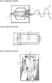
- FIGS. 1a, 1b and 1c schematically show various designs of fluid oscillators as known from the prior art. These are suitable for use in oscillating nozzles 20 according to various aspects of the present invention. However, the present inventions are not limited to these designs of the fluid oscillators. In general, all types of fluid oscillators are suitable.
- the fluid can enter the flow chamber through an inlet 1.
- an acceleration nozzle e.g. in the form of a taper
- the fluid then enters the oscillation chamber 3.
- Flow obstacles 6 in the form of islands 6 may be provided in the oscillation chamber 3.
- return flow channels 4 may also be provided, which redirect parts of the fluid flow back toward the inlet 1.
- the fluid then leaves the oscillator as an oscillating jet 10.
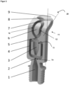
- Figure 2 shows an angled oscillating nozzle 20 according to one aspect of the invention.
- the fluid is introduced into the nozzle 20 via an inlet 1.
- the fluid is then guided through an acceleration nozzle 2 via the oscillator inlet 3a into the oscillator chamber 3.
- An oscillator is shown which comprises two return channels 4.
- the nozzle in Figure 2 a constriction 5.
- the fluid is then directed through two channels 12 separated by an island 6. It is very advantageous if the channels and the island 6 exhibit a high degree of symmetry.
- the island 6 can be circular, elliptical, teardrop-shaped, or similar.
- the channels 12 are reunited, and the fluid then leaves the nozzle 20 as an oscillating jet via the outlet 7.
- the area between the constriction 5 and the outlet 7 is referred to as the wake area 11.
- the oscillating nozzle 20 is angled.
- the nozzle 20 is angled by an exit angle within the wake area. This exit angle can advantageously be between 1° and 90°, in particular between 5° and 45°.
- Figure 2 An angle of 30° is shown as an example.
- the nozzle 20 is provided with Figure 2 A lip 8 is provided. This prevents the jet 20 from deflecting downwards. Alternatively or additionally, a lip 8 may be provided to prevent the jet from deflecting upwards.
- the lip 8 or lips 8 are in Figure 2 not angled or curved, but straight. Bending or curving the lips 8 is also not necessary to deflect the jet, since the bending already occurs beforehand inside the nozzle 20. Nevertheless, in some cases it may be useful to provide an additional curvature or bending in the area of the lips 8.
- Such an angled oscillating nozzle 20 can be used for a variety of applications. In particular, it is ideally suited for use as an oscillating nozzle 20 in a cleaning device 100 according to one aspect of the invention.
- FIG. 3 2 shows an angled oscillating nozzle 20 according to one aspect of the invention in various external views.
- B1 denotes the inlet width after the acceleration nozzle 2
- B2 the width of the constriction 5
- B3 the width of the channels 12
- B4 the width of the outlet 7.
- These four widths B1-B4 combined with the length of the lip 8, influence the shape of the oscillating jet 10.
- a jet spread of 120° in the jet plane which has proven to be very advantageous, can be achieved, for example, if the widths B1 and B2, i.e. the inlet width and the width of the constriction, are the same.
- the width of the channels and the outlet opening can be somewhat wider than the inlet width B1.
- the width B1 can be selected, for example, between 1 mm and 5 mm, in particular 2 mm.
- the geometry of the flow chambers remains the same over their entire height.
- the height H is chosen to be equal to the inlet width B1. This results in a square cross-section of the inlet 1.
- the length of the lip 8 can be at least three times as long as the inlet width B1. This is advantageous for achieving a jet 20 that is focused in the normal direction.
- a very advantageous design of the oscillating nozzle has the following dimensions: B1 B2 B3 B4 H lip 2mm 2mm 2.5mm 3mm 2mm ⁇ 6mm
- the Figures 2 and 3 The nozzles 20 shown each have a thread at their base. This is advantageous for connecting to a fluid supply line. Alternatively, this connection can also be made via a plug-in connection, for example. In both cases, the nozzles 20 can be easily replaced. Depending on the application, other connection types, in particular non-detachable connections to the fluid supply line, can also be provided.
- FIG 4 shows a section of a cleaning device 100 according to one aspect of the invention.
- a cleaning device 100 is particularly suitable as a cleaning device 100 for a suction roll 130 for a system for producing or processing a fibrous web.
- a plurality of cleaning nozzles 120a, 120b are attached to a distribution line 110, which can be designed as a distribution pipe 110. These can be supplied with a cleaning fluid, such as spray water, from the distribution line 110.
- the cleaning fluid can be supplied to the distribution line 110 via a single fluid connection 111 or via multiple fluid connections 111.
- the cleaning nozzles are arranged in Figure 4 all as oscillating nozzles 20.
- the cleaning nozzles are designed as angled oscillating nozzles 20, for example those as shown in the Figures 2 and 3 described.
- the execution in Figure 4 comprises a first set 120a and a second set 120b of angled cleaning nozzles, wherein the exit angle of the jet plane of the first set 120a and the second set 120b differ from one another. A difference of 5° - 10° in the angles is often advantageous.
- the exit angle of the first set 120a can be 30°
- the exit angle of the second set 120b can be 35°.
- FIG. 4 A cleaning device 100 is shown in which the distance between the cleaning nozzles varies.
- the cleaning nozzles are positioned, for example, in groups of two, consisting of one nozzle of the first and one of the second set. This can be advantageous, as will be shown below with reference to Figure 5 c explained
- the distance between adjacent cleaning nozzles can also be the same, for example, 250 mm. However, it can also be provided that in regions where less contamination is expected—for example, at the edge of a suction roller 130—the distances between the cleaning nozzles are larger than in the other regions.
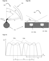
- FIG. 5a The installation situation of a cleaning device 100 in a suction roll 130 is shown.
- the distribution line 110 runs parallel to the axis of the suction roll 130, or at least largely parallel.
- the cleaning device 100 comprises, for example, a first set 120a and a second set 120b of angled oscillating nozzles 20, which are arranged alternately.
- the respective exit angles are designated ⁇ 1 and ⁇ 2.
- the distance between the cleaning device 100 and the casing of the suction roll 130 is I d .
- Figure 5b shows a device as in Figure 5a in plan view.
- the oscillation angle ⁇ W i.e. the angle covered by the oscillating beam 10 during oscillation.
- This oscillation angle can, for example, be between 90° and 170°.
- the nozzles 20 can be arranged such that the areas in which the jets 10 oscillate overlap in adjacent nozzles. It is advantageous here if adjacent nozzles 20, 120a, 120b have different exit angles ⁇ 1, ⁇ 2. This places the jet planes of adjacent nozzles in such a way that the jets do not touch and thus cannot interfere.
- Figure 5a As can be seen, the beam of the first quantity ⁇ 1 hits the casing of the suction roll 130 above the beam of the second quantity ⁇ 2.
- Figure 5c illustrates why an overlap of adjacent jet areas according to one aspect of the invention is not only easily possible, but also advantageous.
- the graph shows the volume flow of fluid from four adjacent oscillating nozzles 20.
- a typical 'M-profile' can be seen, which means that less fluid per unit of time hits the suction roller 130 in the middle of the swept area than towards the edges. This is generally typical for oscillators.
- the distribution of the fluid can be made more uniform by using a trailing area 11, whereby wider oscillation angles ⁇ W or larger swept areas bs become possible.
- the cleaning device 100 can therefore be realized with fewer nozzles 20. It can be seen that the nozzles of the first set 120a are positioned such that their jets do not touch.
- the nozzles of the second set 120b can now be positioned so that the regions with high fluid volume flow are where the nozzles of the first set 120a encounter a lower volume flow, and vice versa. This ensures that, on average, the surface of the suction roll 130—or other moving surfaces to be cleaned or moistened—is uniformly exposed to fluid across its width.
- the cleaning nozzles as in Figure 4 shown, in groups of two consisting of a nozzle of the first and the second set. These two nozzles of a group have the distance I A , while the distance to the first nozzle of the next group of two concerns I B.
- I A 0.25 bs
- I B 0.75 bs This results in a particularly homogeneous cleaning of the suction roll 130. More generally, the distances should be l A ⁇ 0.2 , 0.3 b s ; l B ⁇ 0.7 , 0.8 b s be elected.
Landscapes
- Engineering & Computer Science (AREA)
- General Engineering & Computer Science (AREA)
- Theoretical Computer Science (AREA)
- Physics & Mathematics (AREA)
- Fluid Mechanics (AREA)
- Mechanical Engineering (AREA)
- Nozzles (AREA)
Claims (14)
- Buse oscillante (20), en particulier pour un dispositif de nettoyage (100), dans laquelle la buse oscillante (20) comprend un oscillateur fluidique pourvu d'une chambre d'oscillation (3), et la buse oscillante (20) est réalisée de manière coudée de sorte que le plan de jet est dévié à l'intérieur de la buse (20), la déviation étant effectuée après la chambre d'oscillation (3), caractérisée en ce qu'après la chambre d'oscillation (3), le fluide est guidé par l'intermédiaire de deux canaux (12) séparés par un îlot (6) et qui définissent une zone de sillage (11), et la déviation du plan de jet est effectuée dans cette zone de sillage (11).
- Buse oscillante (20) selon l'une quelconque des revendications précédentes, caractérisée en ce que le plan de jet est dévié d'un angle entre 1° et 90°, en particulier entre 5° et 45°.
- Buse oscillante (20) selon l'une quelconque des revendications précédentes, caractérisée en ce qu'au moins une lèvre (8) est prévue à la sortie de la buse oscillante (20) pour empêcher un élargissement du jet (10) perpendiculairement au plan de jet.
- Buse oscillante (20) selon l'une quelconque des revendications précédentes, caractérisée en ce que le jet oscillant (10) balaie un angle d'oscillation dans la plage entre 90° et 170°, de manière particulièrement préférée un angle de 120°.
- Buse oscillante (20) selon l'une quelconque des revendications précédentes, caractérisée en ce que la buse (20) est composée entièrement ou partiellement d'un métal ou d'une matière plastique.
- Buse oscillante (20) selon l'une quelconque des revendications précédentes, caractérisée en ce que la buse (20) est réalisée d'un seul tenant.
- Dispositif de nettoyage (100), en particulier pour un rouleau aspirant (130), destiné à une installation de fabrication ou de traitement d'une bande de matière fibreuse, le dispositif de nettoyage (100) comprenant une conduite de distribution (110) ainsi qu'un nombre de buses de nettoyage (20) qui peuvent être alimentées en fluide de nettoyage par l'intermédiaire de la conduite de distribution (110) et sont caractérisées en ce qu'au moins une, en particulier toutes les buses de nettoyage, sont réalisées sous la forme de buses oscillantes (20) selon l'une quelconque des revendications 1 à 6.
- Dispositif de nettoyage selon la revendication 7, caractérisé en ce qu'une première quantité (120a) et une deuxième quantité (120b) de buses oscillantes (20) sont prévues, dans lequel l'angle de sortie (θ1, θ2) du plan de jet de la première quantité (120a) et de la deuxième quantité (120b) sont différents l'un de l'autre.
- Dispositif de nettoyage (100) selon l'une quelconque des revendications 7 ou 8, caractérisé en ce que respectivement une buse oscillante de la première quantité (120a) et une buse oscillante de la deuxième quantité (120b) sont disposées en alternance.
- Dispositif de nettoyage (100) selon l'une quelconque des revendications 8 ou 9, caractérisé en ce que l'angle de sortie du plan de jet de la première quantité (120a) et de la deuxième quantité (120b) se distinguent de plus de 2°, en particulier entre 5° et 25°.
- Dispositif de nettoyage (100) selon l'une quelconque des revendications 7 à 10, caractérisé en ce que les buses de nettoyage sont reliées à la conduite de distribution par une liaison amovible, en particulier par une liaison vissée ou enfichable.
- Dispositif de nettoyage (100) selon l'une quelconque des revendications 7 à 11, caractérisé en ce que les buses de nettoyage sont disposées à une distance de moins de 500 mm, en particulier entre 150 mm et 350 mm.
- Rouleau aspirant (130) destiné à une installation de fabrication ou de traitement d'une bande de matière fibreuse, caractérisé en ce que le rouleau aspirant (130) comprend au moins un dispositif de nettoyage (100) selon l'une quelconque des revendications 8 à 12.
- Rouleau aspirant (130) selon la revendication 13, caractérisé en ce que le dispositif de nettoyage (100) est disposé à l'intérieur du rouleau aspirant (130).
Applications Claiming Priority (2)
| Application Number | Priority Date | Filing Date | Title |
|---|---|---|---|
| DE102019120809.2A DE102019120809A1 (de) | 2019-08-01 | 2019-08-01 | Düse |
| PCT/EP2020/063885 WO2021018433A1 (fr) | 2019-08-01 | 2020-05-19 | Buse |
Publications (3)
| Publication Number | Publication Date |
|---|---|
| EP4007659A1 EP4007659A1 (fr) | 2022-06-08 |
| EP4007659C0 EP4007659C0 (fr) | 2025-03-12 |
| EP4007659B1 true EP4007659B1 (fr) | 2025-03-12 |
Family
ID=70847345
Family Applications (1)
| Application Number | Title | Priority Date | Filing Date |
|---|---|---|---|
| EP20727956.3A Active EP4007659B1 (fr) | 2019-08-01 | 2020-05-19 | Buse |
Country Status (5)
| Country | Link |
|---|---|
| US (1) | US12226786B2 (fr) |
| EP (1) | EP4007659B1 (fr) |
| CN (1) | CN114206507A (fr) |
| DE (1) | DE102019120809A1 (fr) |
| WO (1) | WO2021018433A1 (fr) |
Families Citing this family (1)
| Publication number | Priority date | Publication date | Assignee | Title |
|---|---|---|---|---|
| CN114370337B (zh) * | 2022-01-14 | 2023-05-23 | 中国航空发动机研究院 | 一种射流振荡器 |
Family Cites Families (9)
| Publication number | Priority date | Publication date | Assignee | Title |
|---|---|---|---|---|
| US5035361A (en) * | 1977-10-25 | 1991-07-30 | Bowles Fluidics Corporation | Fluid dispersal device and method |
| US20040250837A1 (en) * | 2003-06-13 | 2004-12-16 | Michael Watson | Ware wash machine with fluidic oscillator nozzles |
| DE102007037492A1 (de) * | 2007-08-08 | 2009-02-12 | Volkswagen Ag | Waschflüssigkeitsdüse zur Reinigung einer Scheibe an einem Fahrzeug |
| DE102008002259A1 (de) * | 2008-06-06 | 2009-12-10 | Voith Patent Gmbh | Saugwalze, insbesondere Trockensiebsaugwalze und Verfahren zur Erhöhung der Verfügbarkeit von Saugwalzen |
| US9566593B2 (en) | 2011-04-19 | 2017-02-14 | Delta Faucet Company | Hand shower |
| CN102861679B (zh) * | 2012-10-15 | 2015-07-08 | 江苏大学 | 射流振荡三通 |
| US11186974B2 (en) * | 2015-08-11 | 2021-11-30 | Dlhbowles, Inc. | Fluidic faucet spray face and spray generation method |
| DE102016208344A1 (de) * | 2016-05-13 | 2017-11-16 | Technische Universität Berlin | Fluidisches Bauteil |
| DE102017206849A1 (de) * | 2017-04-24 | 2018-10-25 | Fdx Fluid Dynamix Gmbh | Fluidische Baugruppe |
-
2019
- 2019-08-01 DE DE102019120809.2A patent/DE102019120809A1/de not_active Ceased
-
2020
- 2020-05-19 EP EP20727956.3A patent/EP4007659B1/fr active Active
- 2020-05-19 CN CN202080055024.0A patent/CN114206507A/zh active Pending
- 2020-05-19 WO PCT/EP2020/063885 patent/WO2021018433A1/fr not_active Ceased
- 2020-05-19 US US17/631,944 patent/US12226786B2/en active Active
Also Published As
| Publication number | Publication date |
|---|---|
| EP4007659C0 (fr) | 2025-03-12 |
| DE102019120809A1 (de) | 2021-02-04 |
| US20220280954A1 (en) | 2022-09-08 |
| EP4007659A1 (fr) | 2022-06-08 |
| WO2021018433A1 (fr) | 2021-02-04 |
| CN114206507A (zh) | 2022-03-18 |
| US12226786B2 (en) | 2025-02-18 |
Similar Documents
| Publication | Publication Date | Title |
|---|---|---|
| DE102010056576B4 (de) | Papierherstellungsmaschine und Verfahren zum Herstellen von Papier | |
| EP3692188B1 (fr) | Dispositif permettant l'extrusion de filaments et la fabrication de non-tissés meltspun | |
| EP2931434A1 (fr) | Buse à jet plat | |
| DE4213707A1 (de) | Stoffauflaufeinrichtung für eine Papiermaschine | |
| WO2021018433A1 (fr) | Buse | |
| EP1420089B1 (fr) | Dispositif pour la fabrication de fibres en matière thermoplastique | |
| WO2021018432A1 (fr) | Dispositif de nettoyage pour cylindre aspirant et procédé de nettoyage d'un cylindre aspirant | |
| DE4237310C2 (de) | Stoffauflauf mit Vorrichtung zur Einstellung der Faserorientierung | |
| DE202019005374U1 (de) | Düse | |
| DE69316534T2 (de) | Vorrichtung zur Behandlung eines Garnes mit einer Flüssigkeit | |
| EP2383046B1 (fr) | Dispositif de buse | |
| EP2383047B9 (fr) | Dispositif de buse | |
| EP1753909B1 (fr) | Procede de nettoyage | |
| DE102004001222B4 (de) | Düseneinheit und Gargerät mit einer Düseneinheit | |
| EP3928957B1 (fr) | Buse de soufflage | |
| EP1464754A2 (fr) | Appareil de nettoyage d'une bande en mouvement | |
| EP4046799B1 (fr) | Bec de triangle de pliage et triangle de pliage | |
| EP1770206B1 (fr) | Procédé et système de formage pour la fabrication d'une bande fibreuse | |
| EP3976334B1 (fr) | Dispositif et procédé de fabrication d'une nappe de fibres | |
| DE4430035A1 (de) | Vorrichtung zum Trocknen von Materialbahnen | |
| EP1884589A1 (fr) | Dispositif d'aspiration stable, utilisation et machine destinée à la fabrication de bandes de matière fibreuse dotées d'un tel dispositif d'aspiration | |
| DE102024108561A1 (de) | Sprühdüse | |
| AT13597U1 (de) | Dampfblaskasten | |
| WO2015091432A1 (fr) | Dispositif de nettoyage d'une toile d'une machine à papier | |
| DE202004021014U1 (de) | Vorrichtung zum Reinigen eines umlaufenden Bandes |
Legal Events
| Date | Code | Title | Description |
|---|---|---|---|
| STAA | Information on the status of an ep patent application or granted ep patent |
Free format text: STATUS: UNKNOWN |
|
| STAA | Information on the status of an ep patent application or granted ep patent |
Free format text: STATUS: THE INTERNATIONAL PUBLICATION HAS BEEN MADE |
|
| PUAI | Public reference made under article 153(3) epc to a published international application that has entered the european phase |
Free format text: ORIGINAL CODE: 0009012 |
|
| STAA | Information on the status of an ep patent application or granted ep patent |
Free format text: STATUS: REQUEST FOR EXAMINATION WAS MADE |
|
| 17P | Request for examination filed |
Effective date: 20220301 |
|
| AK | Designated contracting states |
Kind code of ref document: A1 Designated state(s): AL AT BE BG CH CY CZ DE DK EE ES FI FR GB GR HR HU IE IS IT LI LT LU LV MC MK MT NL NO PL PT RO RS SE SI SK SM TR |
|
| DAV | Request for validation of the european patent (deleted) | ||
| DAX | Request for extension of the european patent (deleted) | ||
| GRAP | Despatch of communication of intention to grant a patent |
Free format text: ORIGINAL CODE: EPIDOSNIGR1 |
|
| STAA | Information on the status of an ep patent application or granted ep patent |
Free format text: STATUS: GRANT OF PATENT IS INTENDED |
|
| INTG | Intention to grant announced |
Effective date: 20241021 |
|
| GRAS | Grant fee paid |
Free format text: ORIGINAL CODE: EPIDOSNIGR3 |
|
| GRAA | (expected) grant |
Free format text: ORIGINAL CODE: 0009210 |
|
| STAA | Information on the status of an ep patent application or granted ep patent |
Free format text: STATUS: THE PATENT HAS BEEN GRANTED |
|
| AK | Designated contracting states |
Kind code of ref document: B1 Designated state(s): AL AT BE BG CH CY CZ DE DK EE ES FI FR GB GR HR HU IE IS IT LI LT LU LV MC MK MT NL NO PL PT RO RS SE SI SK SM TR |
|
| REG | Reference to a national code |
Ref country code: GB Ref legal event code: FG4D Free format text: NOT ENGLISH |
|
| REG | Reference to a national code |
Ref country code: CH Ref legal event code: EP |
|
| REG | Reference to a national code |
Ref country code: DE Ref legal event code: R096 Ref document number: 502020010585 Country of ref document: DE |
|
| REG | Reference to a national code |
Ref country code: IE Ref legal event code: FG4D Free format text: LANGUAGE OF EP DOCUMENT: GERMAN |
|
| U01 | Request for unitary effect filed |
Effective date: 20250312 |
|
| U07 | Unitary effect registered |
Designated state(s): AT BE BG DE DK EE FI FR IT LT LU LV MT NL PT RO SE SI Effective date: 20250319 |
|
| PG25 | Lapsed in a contracting state [announced via postgrant information from national office to epo] |
Ref country code: RS Free format text: LAPSE BECAUSE OF FAILURE TO SUBMIT A TRANSLATION OF THE DESCRIPTION OR TO PAY THE FEE WITHIN THE PRESCRIBED TIME-LIMIT Effective date: 20250612 |
|
| PG25 | Lapsed in a contracting state [announced via postgrant information from national office to epo] |
Ref country code: ES Free format text: LAPSE BECAUSE OF FAILURE TO SUBMIT A TRANSLATION OF THE DESCRIPTION OR TO PAY THE FEE WITHIN THE PRESCRIBED TIME-LIMIT Effective date: 20250312 |
|
| PG25 | Lapsed in a contracting state [announced via postgrant information from national office to epo] |
Ref country code: NO Free format text: LAPSE BECAUSE OF FAILURE TO SUBMIT A TRANSLATION OF THE DESCRIPTION OR TO PAY THE FEE WITHIN THE PRESCRIBED TIME-LIMIT Effective date: 20250612 |
|
| PG25 | Lapsed in a contracting state [announced via postgrant information from national office to epo] |
Ref country code: HR Free format text: LAPSE BECAUSE OF FAILURE TO SUBMIT A TRANSLATION OF THE DESCRIPTION OR TO PAY THE FEE WITHIN THE PRESCRIBED TIME-LIMIT Effective date: 20250312 |
|
| PG25 | Lapsed in a contracting state [announced via postgrant information from national office to epo] |
Ref country code: GR Free format text: LAPSE BECAUSE OF FAILURE TO SUBMIT A TRANSLATION OF THE DESCRIPTION OR TO PAY THE FEE WITHIN THE PRESCRIBED TIME-LIMIT Effective date: 20250613 |
|
| U20 | Renewal fee for the european patent with unitary effect paid |
Year of fee payment: 6 Effective date: 20250620 |
|
| PG25 | Lapsed in a contracting state [announced via postgrant information from national office to epo] |
Ref country code: SM Free format text: LAPSE BECAUSE OF FAILURE TO SUBMIT A TRANSLATION OF THE DESCRIPTION OR TO PAY THE FEE WITHIN THE PRESCRIBED TIME-LIMIT Effective date: 20250312 |
|
| PG25 | Lapsed in a contracting state [announced via postgrant information from national office to epo] |
Ref country code: PL Free format text: LAPSE BECAUSE OF FAILURE TO SUBMIT A TRANSLATION OF THE DESCRIPTION OR TO PAY THE FEE WITHIN THE PRESCRIBED TIME-LIMIT Effective date: 20250312 |
|
| PG25 | Lapsed in a contracting state [announced via postgrant information from national office to epo] |
Ref country code: CZ Free format text: LAPSE BECAUSE OF FAILURE TO SUBMIT A TRANSLATION OF THE DESCRIPTION OR TO PAY THE FEE WITHIN THE PRESCRIBED TIME-LIMIT Effective date: 20250312 |
|
| PG25 | Lapsed in a contracting state [announced via postgrant information from national office to epo] |
Ref country code: SK Free format text: LAPSE BECAUSE OF FAILURE TO SUBMIT A TRANSLATION OF THE DESCRIPTION OR TO PAY THE FEE WITHIN THE PRESCRIBED TIME-LIMIT Effective date: 20250312 |
|
| PG25 | Lapsed in a contracting state [announced via postgrant information from national office to epo] |
Ref country code: IS Free format text: LAPSE BECAUSE OF FAILURE TO SUBMIT A TRANSLATION OF THE DESCRIPTION OR TO PAY THE FEE WITHIN THE PRESCRIBED TIME-LIMIT Effective date: 20250712 |
|
| REG | Reference to a national code |
Ref country code: CH Ref legal event code: H13 Free format text: ST27 STATUS EVENT CODE: U-0-0-H10-H13 (AS PROVIDED BY THE NATIONAL OFFICE) Effective date: 20251223 |
|
| PLBE | No opposition filed within time limit |
Free format text: ORIGINAL CODE: 0009261 |
|
| STAA | Information on the status of an ep patent application or granted ep patent |
Free format text: STATUS: NO OPPOSITION FILED WITHIN TIME LIMIT |
|
| PG25 | Lapsed in a contracting state [announced via postgrant information from national office to epo] |
Ref country code: CH Free format text: LAPSE BECAUSE OF NON-PAYMENT OF DUE FEES Effective date: 20250531 |
|
| REG | Reference to a national code |
Ref country code: CH Ref legal event code: L10 Free format text: ST27 STATUS EVENT CODE: U-0-0-L10-L00 (AS PROVIDED BY THE NATIONAL OFFICE) Effective date: 20260121 |
|
| PG25 | Lapsed in a contracting state [announced via postgrant information from national office to epo] |
Ref country code: MC Free format text: LAPSE BECAUSE OF FAILURE TO SUBMIT A TRANSLATION OF THE DESCRIPTION OR TO PAY THE FEE WITHIN THE PRESCRIBED TIME-LIMIT Effective date: 20250312 |
|
| 26N | No opposition filed |
Effective date: 20251215 |
|
| GBPC | Gb: european patent ceased through non-payment of renewal fee |
Effective date: 20250612 |
|
| PG25 | Lapsed in a contracting state [announced via postgrant information from national office to epo] |
Ref country code: GB Free format text: LAPSE BECAUSE OF NON-PAYMENT OF DUE FEES Effective date: 20250612 |
|
| PG25 | Lapsed in a contracting state [announced via postgrant information from national office to epo] |
Ref country code: IE Free format text: LAPSE BECAUSE OF NON-PAYMENT OF DUE FEES Effective date: 20250519 |