EP4007680B1 - Système de cuisson robotisé - Google Patents
Système de cuisson robotisé Download PDFInfo
- Publication number
- EP4007680B1 EP4007680B1 EP20771934.5A EP20771934A EP4007680B1 EP 4007680 B1 EP4007680 B1 EP 4007680B1 EP 20771934 A EP20771934 A EP 20771934A EP 4007680 B1 EP4007680 B1 EP 4007680B1
- Authority
- EP
- European Patent Office
- Prior art keywords
- tray
- ingredient
- designed
- holding
- pot
- Prior art date
- Legal status (The legal status is an assumption and is not a legal conclusion. Google has not performed a legal analysis and makes no representation as to the accuracy of the status listed.)
- Active
Links
Images


Classifications
-
- B—PERFORMING OPERATIONS; TRANSPORTING
- B25—HAND TOOLS; PORTABLE POWER-DRIVEN TOOLS; MANIPULATORS
- B25J—MANIPULATORS; CHAMBERS PROVIDED WITH MANIPULATION DEVICES
- B25J11/00—Manipulators not otherwise provided for
-
- A—HUMAN NECESSITIES
- A47—FURNITURE; DOMESTIC ARTICLES OR APPLIANCES; COFFEE MILLS; SPICE MILLS; SUCTION CLEANERS IN GENERAL
- A47J—KITCHEN EQUIPMENT; COFFEE MILLS; SPICE MILLS; APPARATUS FOR MAKING BEVERAGES
- A47J44/00—Multi-purpose machines for preparing food with several driving units
-
- A—HUMAN NECESSITIES
- A23—FOODS OR FOODSTUFFS; TREATMENT THEREOF, NOT COVERED BY OTHER CLASSES
- A23L—FOODS, FOODSTUFFS OR NON-ALCOHOLIC BEVERAGES, NOT OTHERWISE PROVIDED FOR; PREPARATION OR TREATMENT THEREOF
- A23L5/00—Preparation or treatment of foods or foodstuffs, in general; Food or foodstuffs obtained thereby; Materials therefor
-
- A—HUMAN NECESSITIES
- A47—FURNITURE; DOMESTIC ARTICLES OR APPLIANCES; COFFEE MILLS; SPICE MILLS; SUCTION CLEANERS IN GENERAL
- A47J—KITCHEN EQUIPMENT; COFFEE MILLS; SPICE MILLS; APPARATUS FOR MAKING BEVERAGES
- A47J27/00—Cooking-vessels
- A47J27/004—Cooking-vessels with integral electrical heating means
-
- B—PERFORMING OPERATIONS; TRANSPORTING
- B25—HAND TOOLS; PORTABLE POWER-DRIVEN TOOLS; MANIPULATORS
- B25J—MANIPULATORS; CHAMBERS PROVIDED WITH MANIPULATION DEVICES
- B25J11/00—Manipulators not otherwise provided for
- B25J11/0045—Manipulators used in the food industry
-
- B—PERFORMING OPERATIONS; TRANSPORTING
- B25—HAND TOOLS; PORTABLE POWER-DRIVEN TOOLS; MANIPULATORS
- B25J—MANIPULATORS; CHAMBERS PROVIDED WITH MANIPULATION DEVICES
- B25J15/00—Gripping heads and other end effectors
- B25J15/04—Gripping heads and other end effectors with provision for the remote detachment or exchange of the head or parts thereof
Definitions
- the invention relates to automatic cooking devices and systems, in particular, robotic systems for preparing meals.
- Robotic cooking systems become a solution for such growing demands.
- a cooker having a receptacle, the receptacle comprising a pot for holding ingredients, a heater for induction heating said pot and means for rotating the pot, said receptacle being supported by a main unit so that it can be inclined freely, wherein the cooker further comprises an angle control unit, which provides driving force for inclining said receptacle and a controller for controlling said angle control unit.
- an automatic cooking device comprising a housing, having an ingredients storage means, which has containers and a controllable dispensing means located in the base of each container; the dispensing means are designed to dispense ingredients into a mixing unit provided below the ingredients storage means.
- the mixing chamber has a controllable outlet in its base to dispense ingredients downwards into a cooking pot.
- a heater means cooks the ingredients in the cooking pot.
- the device further optionally comprises an automated cleaning means having multiple nozzles.
- a robotic cooking system comprising one or more robots having means to move food containers between multiple positions and means to stir food within a cooking pan, a food storage and selection area, a cooking area within a range of motion of the robot, at least one food container containing food ingredients and a loading conveyor to move the food container to the cooking area; the robot is configured to move food ingredients from the loading conveyor into a cooking pan, held by the robot in a position over a cooking element in the cooking area.
- the robot uses the means to move food containers to unload food into a serving dish, which is moved by a conveyor to a serving area.
- a food preparation system comprising a housing comprising a wall; a control subsystem configured to control a plurality of food preparation processes capable of preparing a meal comprising a variety of foods based on user selection of the foods; plurality of ingredient storage containers comprising dry ingredient storage containers and liquid ingredient storage containers; a storage module configured to store the ingredient storage containers and a variety of ingredients contained within the ingredient storage containers for an extended period; an ingredient manipulator configured to access and remove a plurality of ingredients from the ingredient storage containers, as commanded by the control subsystem; a cooking receptacle disposed within the housing, the cooking receptacle being configured to cook ingredients placed therein by the ingredient manipulator; a dish and food transfer area; and a cleaning subsystem configured to clean the cooking receptacle and the surface of the wall of the housing.
- an automated meal production system comprising a plurality of ingredient holding and dispensing assemblies, each of the ingredient holding and dispensing assemblies comprising a container for holding a supply of an ingredient and a dispenser for dispensing an amount of the ingredient from a discharge of the ingredient holding and dispensing assembly and a plurality of heating and mixing assemblies which each comprise a heating pot configured for rotating the heating pot about its longitudinal rotational axis, each of the heating pots comprising an opening at an outer end of the heating pot through which the ingredients dispensed by one or more of the ingredient holding and dispensing assemblies are delivered into the heating pot; a side wall which extends longitudinally from the closed base end and surrounds the longitudinal rotational axis; a heating cavity within the heating pot which is surrounded by the side wall, and an interior surface of the side wall which is within and which surrounds the heating cavity, each of the heating pots also comprising an internal mixing fin structure which runs longitudinally along and is formed on or attached to the interior surface of side wall so that
- the invention provides a robotic cooking system, comprising: a robotic arm with a controller and a motor drive unit, an end of arm tool comprising a gripper, a rotary drive; a plurality of ingredient holding and dispensing assemblies, each of the ingredient holding and dispensing assemblies comprising a container for holding a supply of an ingredient and dispenser for dispensing an amount of the ingredient from a discharge of the ingredient holding and dispensing assembly; a cooking receptacle, being configured to cook food ingredients placed therein; dishes storing device; a tray adapted to receive food ingredients from the dispenser and designed to be releasably gripped by the gripper; a dish and food transfer area having at least one compartment, comprising an internal access door, an external access door and at least one surface adapted for placing a dish or food; a cleaning subsystem configured to clean the cooking receptacle and the tray; optionally, a trash compartment.
- the end of arm tool is further provided with a rotary drive adapted to be releasably engaged with the engagement means of a plurality of the containers for holding a supply of an ingredient designed so that at the engaged position the rotation of the rotary drive of the robotic arm causes the dispenser to dispense an amount of the ingredient from the discharge of the ingredient holding and dispensing assembly.
- the rotary drive is provided with a flexible coupling adapted to compensate misalignment and/or ensure easy entering of the end of the engaging part of the rotary drive to the engagement means of a plurality of containers.
- the end of arm tool is further provided with one or more air nozzles directed towards the inner part of the tray, so to create air flow along the surface of the tray towards a discharge edge of the tray to facilitate discharging food ingredients from the tray.
- the proposed design of the robotic cooking system allows to avoid using number of motors in each container for holding a supply of an ingredient as a motor on the robotic arm, operably connected with the rotary drive of the robotic arm, after engagement with the engagement means on the containers causes the dispenser to dispense an amount of the ingredient. This, in turn, allows to simplify construction and makes less expensive the robotic cooking system.
- the subset of the plurality of ingredient holding and dispensing assemblies comprises a container with the dispenser and a screw conveyor, adapted to controllably move fluent solid ingredients in the container towards the dispenser, wherein the screw conveyor comprises two helically bladed screws: a central screw and a peripheral screw, the peripheral screw located around the central screw, both screws having the same rotational axis; wherein the helical blades of the screws have opposite directions.
- the screw conveyor comprises two helically bladed screws: a central screw and a peripheral screw, the peripheral screw located around the central screw, both screws having the same rotational axis; wherein the helical blades of the screws have opposite directions.
- the tray is designed to have two parallel substantially vertical walls and two substantially inclined walls; where the two inclined walls, together with the tray's bottom form an arc, preferably a parabolic arc.
- This advantageously allows to create air flow paths along the surface of the tray towards a discharge edge of the tray and thus, to facilitate discharging food ingredients from the tray.
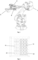
- the proposed robotic cooking system comprising: a robotic arm 1 ( Fig. 1 ) with a controller and a motor drive unit, an end of arm tool 2; a plurality of ingredient holding and dispensing assemblies 20 ( Fig. 2 ); a cooking receptacle 3, being configured to cook food ingredients placed therein ( Fig. 3 ); dishes storing device 4 ( Fig. 4 ); a tray 5 ( Fig. 5 ).
- the robotic cooking system further comprises a cleaning subsystem 7' and 7" configured to clean the cooking receptacle 3 and the tray 5.
- Each of the ingredient holding and dispensing assemblies comprises a container 21 for holding a supply of an ingredient and dispenser 22 ( Fig. 6 , Fig. 9 ) for dispensing an amount of the ingredient from a discharge 23 of the ingredient holding and dispensing assembly 20.
- the containers 21 for holding a supply of an ingredient comprise a plurality of containers adapted for holding a supply of liquid ingredients (such as water, milk, sauce) or viscous substance (such as oil, ketchup, mashed potato) - Fig. 9 , and containers adapted for holding a supply of solid ingredients (such as pre-chopped meat, beans, rice, potato) - Fig. 6-8 .
- the dispenser 22 is adapted to be actuated from a closed position to retain ingredients within the container, partly open position, and an open position such that ingredients are allowed to controllably fall through it or be controllably dispensed through it.
- the dispenser 22 can be controllable by a control means.
- the end of arm tool 2 is further provided with one or more air nozzles 11 ( Fig. 5 ) directed towards the inner part of the tray 5, so to create air flow along the surface of the tray 5 towards a discharge edge of the tray 5 to facilitate discharging food ingredients from the tray 5 to e.g. cooking receptacle 3.
- the tray 5 is designed to receive food ingredients from the dispenser 22 and designed to be releasably gripped by the gripper 8 located on the end of arm tool 2.
- the tray 5 has two parallel substantially vertical walls 30 (where the term "substantially” in the present description allows deviation to up to five degrees) and two inclined walls 31; where the two inclined walls 31, together with the tray's 5 bottom 32 form an arc, preferably a parabolic arc.
- the tray's 5 bottom 32 is fixed to a balancing or holding means 33 adapted to ensure stable placement of the tray 5 on the required surface in the robotic cooking system.
- the required surface can be flat and horizontal and can be inclined.
- the balancing or holding means 33 can be in the form of a plate, one or more strips, a magnet, or equivalent means.
- the shape of the tray 5 allows to more effectively direct air flow paths from the air nozzles 11, along the surface of the tray 5 towards a discharge edge of the tray 5 to facilitate discharging food ingredients from the tray 5.
- the tray 5 is provided with gripping area 34, adapted to be gripped by the gripper located on the end of arm tool 2.
- the gripping area 34 may be in the form of two horizontal bars 35 fixed to the upper part of the parallel substantially vertical walls 30, where the horizontal bars 35 are provided with engagement means for engaging with the gripper 8.
- the horizontal bars 35 are designed to create a protective edge to shield the robotic arm 1 electronics from spilling of food ingredients from the tray 5 as well as liquid during washing of the tray 5 in the cleaning subsystem 7' and 7".
- the cooking receptacle 3 is configured to cook food ingredients placed therein ( Fig. 3 ).
- the cooking receptacle 3 comprises a pot 12 designed for holding ingredients, one or more heaters 13 for induction heating the pot 12 and rotating means 15 for rotating the pot 12 about two or more rotational axis: for rotation of the pot 12 during cooking of the ingredients about an axis inclined at about 10-50 degrees from the vertical, so that the ingredients remain in the pot 12, as well as for rotation of the pot 12 in the vertical plane for discharging the ingredients into a servicing dish.
- the pot 12 has a substantially spherical bottom and an opening in the upper part, which is adapted to receive food ingredients from the discharge edge of the tray 5 and the dispenser 22 of a container 21".
- the pot 12 preferably has a narrowing upper part designed to prevent spilling out of food ingredients from the tray 5 during rotation of the pot 12 in cooking position, when the pot 12 is inclined about 45-50 degrees from the verticality.
- the pot 12 further comprises one or two fins 14 adapted to be rotated inside the pot 12 in order to ensure uniform stirring of food ingredients in the pot 12, wherein the cooking receptacle 3 is designed to controllably rotate the fins 14 in the direction, which is opposite to the direction of rotation of the pot 12.
- the dishes storing device 4 comprises a frame and means for holding dishes (e.g. disposable dishes), as well as means for supplying dishes towards the opening of the dishes storing device 4 and separating the dishes, so that they can be picked by the gripper 8 ( Fig. 4 ).
- dishes e.g. disposable dishes
- the gripper 8 Fig. 4
- the dish and food transfer area 6 is designed to serve cooked meals to a customer ( Fig. 10 ).
- the dish and food transfer area 6 has one or more compartments, comprising at least an internal access door and at least one surface adapted for placing a dish or food therein.
- the dish and food transfer area 6 may further comprise an external access door.
- the robotic arm 1 comprises an arm base, an arm, an end of arm tool 2, a gripper 8 attached to the arm.
- the end of arm tool 2 is further provided with a rotary drive 9 adapted to be releasably engaged with engagement means 10 of a plurality of the containers 21 for holding a supply of an ingredient designed so that at the engaged position the rotation of the rotary drive 9 of the end of arm tool 2 causes the dispenser 22 of the ingredient holding and dispensing assembly 20 to dispense an amount of the ingredient from the discharge 23 of the ingredient holding and dispensing assembly 20.
- the rotary drive 9 is provided with a flexible coupling 9' adapted to compensate misalignment and ensure easy entering of the end of the engaging part of the rotary drive 9 to the engagement means 10 of a plurality of the containers 21.
- the flexible coupling 9' can be in the form of bellow coupling, beam coupling, jaw coupling, Oldham coupling and other type.
- the end of arm tool 2 further comprising one or more load cells, adapted to provide a representation (e.g. digital) of a load thereon, the gripper 8 being directly or indirectly associated with said plurality of load cells.
- the gripper 8 of the end of arm tool 2 are designed to be able to pick out and securely relocate a servicing dish. To be able to securely relocate a servicing dish the gripper 8 has a cutout corresponding to a shape of the external part of the servicing dish.
- the cleaning subsystem comprises a subsystem 7' adapted to clean the cooking receptacle 3 ( Fig. 3 ) and a subsystem 7" adapted to clean the tray 5 ( Fig. 11 ).
- the subsystem 7" is designed in the form of a closed bath 16, having openings adapted to receive the tray 5.
- the bath 16 comprises a washing nozzle 17 operably fixed to a pump and means for moving the washing nozzle 18 substantially perpendicularly towards the washable surface of the tray 5.
- the means for moving the washing nozzle 18 are designed to be driven by the rotary drive 9.
- the means for moving the washing nozzle 18 are also provided with the engagement means 10, which are the same as the engagement means 10 of a plurality of the containers 21.
- the subset of the plurality of ingredient holding and dispensing assemblies 20 comprises a container 21' with the dispenser 22 and a screw conveyor 24, adapted to controllably move fluent solid ingredients in the container 21' towards the dispenser 22.
- the screw conveyor 24 comprises two helically bladed screws: a central screw 25 and a peripheral screw 26, located around the central screw 25, both screws having the same rotational axis ( Fig. 7-8 ).
- the helical blades of the screws 25 and 26 have opposite directions (left and right), so that as a result of rotation of a rotational shaft of the screws 25 and 26, the screws 25 and 26 force the contents of the container 21' to move in opposite directions: one towards the dispenser 22 and the other - in opposite direction.
- the helical blades of the screws 25 and 26 are in the shape of a helical coil.
- a rotational shaft of both screws 25 and 26 is provided with engagement means 10 designed to be releasably engaged with the rotary drive 9 of the end of arm tool 2.
- the container 21' preferably has a U-shape crossection ( Fig. 7 ).
- the subset of the plurality of ingredient holding and dispensing assemblies 20 comprises a container 21" and a peristaltic pump 27, which drive is designed to be releasably engaged with the rotary drive 9 of the end of arm tool 2.
- Each container 21" is designed to allow the gripper 8 to grip and releasably fix the container 21", as well as to remove it from its storage location, bring it towards the cooking receptacle 3 and back to the storage location.
- the container 21" is designed to accommodate a replaceable sealed receptacle operably connected with the peristaltic pump 27 and the dispenser 22 by means of flexible pipe.
- the robotic cooking system may further comprise a ventilation, humidity and temperature controlling system adapted to ensure the pre-set level of humidity and temperature in the robotic cooking system.
Landscapes
- Engineering & Computer Science (AREA)
- Food Science & Technology (AREA)
- Robotics (AREA)
- Mechanical Engineering (AREA)
- Life Sciences & Earth Sciences (AREA)
- Health & Medical Sciences (AREA)
- Nutrition Science (AREA)
- Chemical & Material Sciences (AREA)
- Polymers & Plastics (AREA)
- Manipulator (AREA)
- Food-Manufacturing Devices (AREA)
Claims (9)
- Système de cuisson robotisé, comprenant: un bras robotisé (1) avec un dispositif de commande et une unité d'entraînement de moteur, un outil d'extrémité de bras (2) avec un organe de préhension (8) ; une pluralité d'ensembles de retenue et de distribution d'ingrédients (20), chacun des ensembles de retenue et de distribution d'ingrédients comprenant un récipient (21) pour retenir une alimentation d'un ingrédient et un distributeur (22) permettant de distribuer une quantité de l'ingrédient à partir d'une évacuation (23) de l'ensemble de retenue et de distribution d'ingrédients (20) ; un réceptacle de cuisson (3), étant conçu pour cuire des ingrédients alimentaires placés à l'intérieur de celui-ci ; un dispositif de stockage de vaisselle (4) ; un plateau (5) adapté pour recevoir des ingrédients alimentaires en provenance du distributeur (22) et destiné à être pris de manière libérable par l'organe de préhension (8); une zone de transfert de vaisselle et d'aliments (6) ayant au moins un compartiment; un sous-système de nettoyage (7' et 7") conçu pour nettoyer le réceptacle de cuisson (3) et le plateau (5) ; dans lequel l'outil d'extrémité de bras (2) est en outre pourvu d'un entraînement rotatif (9) adapté pour être mis en prise de manière libérable avec les moyens de mise en prise (10) d'une pluralité des récipients (21) pour retenir une alimentation d'un ingrédient conçu de sorte qu'à la position en prise la rotation de l'entraînement rotatif (9) de l'outil d'extrémité de bras (2) amène le distributeur (22) de l'ensemble de retenue et de distribution d'ingrédients (20) à distribuer une quantité de l'ingrédient à partir de l'évacuation (23) de l'ensemble de retenue et de distribution d'ingrédients (20) ; dans lequel l'entraînement rotatif (9) est pourvu d'un accouplement flexible (9') adapté pour compenser un désalignement et/ou assurer une entrée aisée de l'extrémité de la partie de mise en prise de l'entraînement rotatif (9) dans les moyens de mise en prise (10) d'une pluralité des récipients (21), dans lequel l'outil d'extrémité de bras (2) est en outre pourvu d'une ou plusieurs buses d'air (11) dirigées vers la partie intérieure du plateau (5), de façon à créer un flux d'air le long de la surface du plateau (5) en direction d'un bord d'évacuation du plateau (5) pour faciliter l'évacuation d'ingrédients alimentaires du plateau (5).
- Système de cuisson robotisé selon la revendication 1, dans lequel un sous-ensemble de la pluralité d'ensembles de retenue et de distribution d'ingrédients (20) comprend un récipient (21') avec le distributeur (22) et un convoyeur à vis (24), adapté pour déplacer de manière commandée des ingrédients solides fluides dans le récipient (21') en direction du distributeur (22), dans lequel le convoyeur à vis (24) comprend deux vis à lame hélicoïdale : une vis centrale (25) et une vis périphérique (26), la vis périphérique (26) étant localisée autour de la vis centrale (25), l'une et l'autre des vis ayant le même axe de rotation ; dans lequel les lames hélicoïdales des vis (25 et 26) ont des directions opposées ; un arbre de rotation de l'une et l'autre des vis (25 et 26) est pourvu de moyens de mise en prise (10) destinés à être mis en prise de manière libérable avec l'entraînement rotatif (9) de l'outil d'extrémité de bras (2).
- Système de cuisson robotisé selon de quelconques revendications précédentes, dans lequel un sous-ensemble de la pluralité d'ensembles de retenue et de distribution d'ingrédients (20) comprend un récipient (21") et une pompe péristaltique (27), cet entraînement étant destiné à être mis en prise de manière libérable avec l'entraînement rotatif (9) de l'outil d'extrémité de bras (2) ; dans lequel chaque récipient (21") est destiné à permettre à l'organe de préhension (8) de prendre et de fixer de manière libérable le récipient (21"), ainsi que de le retirer de sa localisation de stockage et le ramener à sa localisation de stockage.
- Système de cuisson robotisé selon de quelconques revendications précédentes, dans lequel le récipient (21") est conçu pour recevoir un réceptacle scellé remplaçable relié fonctionnellement à la pompe péristaltique (27) et au distributeur (22) au moyen d'un tuyau flexible.
- Système de cuisson robotisé selon de quelconques revendications précédentes, dans lequel le réceptacle de cuisson (3) comprend une casserole (12) permettant de retenir des ingrédients, un ou plusieurs éléments chauffants (13) pour un chauffage par induction de la casserole (12) et des moyens de rotation (15) permettant de mettre en rotation la casserole (12) autour de deux axes de rotation ou plus, dans lequel la casserole (12) est en outre pourvue d'une ou deux ailettes (14) adaptées pour être mises en rotation à l'intérieur de la casserole (12) afin d'assurer une agitation homogène des ingrédients alimentaires dans la casserole (12), dans lequel le réceptacle de cuisson (3) est destiné à mettre en rotation de manière commandée les ailettes (14) dans la direction, qui est opposée à la direction de rotation de la casserole (12).
- Système de cuisson robotisé selon de quelconques revendications précédentes, dans lequel le plateau (5) est destiné à avoir deux parois parallèles sensiblement verticales (30) et deux parois sensiblement inclinées (31) ; où les deux parois inclinées (31), conjointement avec le fond (32) du plateau (5) forment un arc, de préférence un arc parabolique.
- Système de cuisson robotisé selon de quelconques revendications précédentes, dans lequel le sous-système de nettoyage (7') est adapté pour nettoyer le réceptacle de cuisson (3) et un sous-système (7") est adapté pour nettoyer le plateau (5), dans lequel le sous-système (7") est conçu sous la forme d'un bain fermé (16), ayant des ouvertures adaptées pour recevoir le plateau (5), le bain (16) comprenant une buse de lavage (17) fixée fonctionnellement à une pompe et à des moyens de déplacement de la buse de lavage (18), dans lequel les moyens de déplacement de la buse de lavage (18) sont pourvus des moyens de mise en prise (10), qui sont les mêmes que les moyens de mise en prise (10) d'une pluralité des récipients (21), où les moyens de déplacement de la buse de lavage (18) sont destinés à être entraînés par l'entraînement rotatif (9).
- Système de cuisson robotisé selon de quelconques revendications précédentes, dans lequel le plateau (5) est en outre pourvu d'une zone de préhension (34), adaptée pour être prise par l'organe de préhension (8), où la zone de préhension (34) est sous la forme de deux barres horizontales (35) fixées à la partie supérieure des parois parallèles sensiblement verticales (30), où les barres horizontales (35) sont pourvues de moyens de mise en prise pour venir en prise avec l'organe de préhension (8).
- Système de cuisson robotisé selon de quelconques revendications précédentes, dans lequel l'outil d'extrémité de bras (2) comprend en outre une ou plusieurs cellules de charge, adaptées pour fournir une représentation d'une charge sur l'organe de préhension (8), l'organe de préhension (8) étant directement ou indirectement associé à ladite pluralité de cellules de charge.
Applications Claiming Priority (2)
| Application Number | Priority Date | Filing Date | Title |
|---|---|---|---|
| LVP-19-52A LV15561A (lv) | 2019-10-03 | 2019-10-03 | Robotizēta ēdienu pagatavošanas sistēma |
| PCT/LV2020/050002 WO2021066637A1 (fr) | 2019-10-03 | 2020-08-28 | Système de cuisson robotisé |
Publications (3)
| Publication Number | Publication Date |
|---|---|
| EP4007680A1 EP4007680A1 (fr) | 2022-06-08 |
| EP4007680B1 true EP4007680B1 (fr) | 2025-02-12 |
| EP4007680C0 EP4007680C0 (fr) | 2025-02-12 |
Family
ID=68382474
Family Applications (2)
| Application Number | Title | Priority Date | Filing Date |
|---|---|---|---|
| EP20771934.5A Active EP4007680B1 (fr) | 2019-10-03 | 2020-08-28 | Système de cuisson robotisé |
| EP20801414.2A Active EP4007681B1 (fr) | 2019-10-03 | 2020-09-29 | Outil d'extrémité de bras pour système de cuisson robotique |
Family Applications After (1)
| Application Number | Title | Priority Date | Filing Date |
|---|---|---|---|
| EP20801414.2A Active EP4007681B1 (fr) | 2019-10-03 | 2020-09-29 | Outil d'extrémité de bras pour système de cuisson robotique |
Country Status (5)
| Country | Link |
|---|---|
| US (2) | US20220338679A1 (fr) |
| EP (2) | EP4007680B1 (fr) |
| CA (1) | CA3155115C (fr) |
| LV (1) | LV15561A (fr) |
| WO (2) | WO2021066637A1 (fr) |
Families Citing this family (4)
| Publication number | Priority date | Publication date | Assignee | Title |
|---|---|---|---|---|
| KR20220135178A (ko) * | 2021-03-29 | 2022-10-06 | 가부시키가이샤 노리타케 캄파니 리미티드 | 피소성물 취출 장치 |
| CN115708649B (zh) * | 2022-11-22 | 2025-07-15 | 银都餐饮设备股份有限公司 | 油炸食物制备系统 |
| WO2024154125A1 (fr) | 2023-01-17 | 2024-07-25 | Savoreat Ltd. | Unité d'alimentation en ingrédients de type pâte dans un robot culinaire |
| KR102852825B1 (ko) * | 2024-12-26 | 2025-09-02 | 주식회사 한국로보틱스 | 복수의 모드를 통해 대용량 조리를 수행하는 대용량 조리 로봇시스템 |
Family Cites Families (34)
| Publication number | Priority date | Publication date | Assignee | Title |
|---|---|---|---|---|
| JPS5431816B2 (fr) * | 1973-12-14 | 1979-10-09 | ||
| JPS5930693A (ja) * | 1982-08-11 | 1984-02-18 | フアナツク株式会社 | ロボツトのダブルハンド |
| AU6897691A (en) | 1989-12-14 | 1991-07-18 | Mitsubishi Denki Kabushiki Kaisha | Cooker |
| US5197846A (en) * | 1989-12-22 | 1993-03-30 | Hitachi, Ltd. | Six-degree-of-freedom articulated robot mechanism and assembling and working apparatus using same |
| WO1992005410A1 (fr) * | 1990-09-17 | 1992-04-02 | Anritsu Corporation | Systeme de mesure servant a mesurer facilement avec un grande precision une large gamme de produits, y compris des substances visqueuses |
| US5131706A (en) * | 1991-07-01 | 1992-07-21 | Rockwell International Corporation | Straight line gripper tool and changer |
| US5342098A (en) * | 1993-01-21 | 1994-08-30 | Snap-Tite, Inc. | Multiple coupling device |
| US6674564B2 (en) * | 2001-06-15 | 2004-01-06 | Maniabarco, Inc. | System, method and article of manufacture for a beam splitting acousto-optical modulator |
| US7174830B1 (en) | 2003-06-05 | 2007-02-13 | Dawei Dong | Robotic cooking system |
| US8276505B2 (en) | 2004-02-18 | 2012-10-02 | David Benjamin Buehler | Food preparation system |
| US8989893B2 (en) * | 2006-01-31 | 2015-03-24 | Robofusion, Inc. | Method and apparatus for dispensing frozen confectionery |
| US7570358B2 (en) * | 2007-03-30 | 2009-08-04 | Asml Netherlands Bv | Angularly resolved scatterometer, inspection method, lithographic apparatus, lithographic processing cell device manufacturing method and alignment sensor |
| US9131807B2 (en) * | 2010-06-04 | 2015-09-15 | Shambhu Nath Roy | Robotic kitchen top cooking apparatus and method for preparation of dishes using computer recipies |
| NL2004830C2 (nl) | 2010-06-07 | 2011-12-08 | Pex Rent B V | Grijpinrichting. |
| JP6029283B2 (ja) * | 2012-02-08 | 2016-11-24 | 株式会社アドバンテスト | 波長変換装置、光源装置、および波長変換方法 |
| CN202858799U (zh) * | 2012-09-17 | 2013-04-10 | 黑龙江省发现者厨房机器人科技有限公司 | 全功能烹饪机器人液体佐料加入装置 |
| JP5717007B2 (ja) * | 2012-11-19 | 2015-05-13 | 株式会社安川電機 | ロボットシステム、ロボットハンド、ロボット |
| US11363916B2 (en) * | 2016-11-14 | 2022-06-21 | Zhengxu He | Automatic kitchen system |
| US20140230660A1 (en) * | 2013-02-19 | 2014-08-21 | Zhengxu He | Scalable automated cooking system having small footprint and reduced labor cost |
| US11096514B2 (en) * | 2016-11-14 | 2021-08-24 | Zhengxu He | Scalable automated kitchen system |
| TWI483209B (zh) * | 2013-07-03 | 2015-05-01 | Chyi Yeu Lin | 自動供餐系統 |
| GB2521999A (en) | 2013-10-19 | 2015-07-15 | Chinua Odi | An automatic cooking device |
| US10154762B2 (en) | 2015-05-07 | 2018-12-18 | Spyce Food Co. | Automated meal production system and apparatus |
| US10987816B2 (en) * | 2016-04-01 | 2021-04-27 | Korea Institute Of Machinery & Materials | Passive stiffness gripper |
| JP6518212B2 (ja) * | 2016-06-06 | 2019-05-22 | 川崎重工業株式会社 | 食品の詰め込み装置 |
| WO2018049249A1 (fr) * | 2016-09-09 | 2018-03-15 | Mark Ganninger | Système et procédé de préparation automatisée de matériaux à base d'aliments |
| US20190125126A1 (en) * | 2016-11-04 | 2019-05-02 | Adam Cohen | Methods and Apparatus for Automated Food Preparation |
| US11351673B2 (en) * | 2017-03-06 | 2022-06-07 | Miso Robotics, Inc. | Robotic sled-enhanced food preparation system and related methods |
| US10327583B2 (en) * | 2017-03-06 | 2019-06-25 | Keenwawa, Inc. | Automatic food preparation apparatus |
| US12251048B2 (en) * | 2017-08-04 | 2025-03-18 | Chef Jasper Inc. | System for automatically preparing meals according to a selected recipe and method for operating the same |
| US11192258B2 (en) * | 2018-08-10 | 2021-12-07 | Miso Robotics, Inc. | Robotic kitchen assistant for frying including agitator assembly for shaking utensil |
| KR20210066805A (ko) * | 2018-10-05 | 2021-06-07 | 소니그룹주식회사 | 조리 시스템 |
| US11410250B2 (en) * | 2018-11-19 | 2022-08-09 | Zhengxu He | Automated restaurant |
| GB2582321A (en) * | 2019-03-19 | 2020-09-23 | Karakuri Ltd | A configurable robotic processing system |
-
2019
- 2019-10-03 LV LVP-19-52A patent/LV15561A/lv unknown
-
2020
- 2020-08-28 US US17/765,981 patent/US20220338679A1/en not_active Abandoned
- 2020-08-28 EP EP20771934.5A patent/EP4007680B1/fr active Active
- 2020-08-28 WO PCT/LV2020/050002 patent/WO2021066637A1/fr not_active Ceased
- 2020-08-28 CA CA3155115A patent/CA3155115C/fr active Active
- 2020-09-29 EP EP20801414.2A patent/EP4007681B1/fr active Active
- 2020-09-29 WO PCT/LV2020/050005 patent/WO2021066638A1/fr not_active Ceased
- 2020-09-29 US US17/765,991 patent/US12419467B2/en active Active
Also Published As
| Publication number | Publication date |
|---|---|
| US20220338679A1 (en) | 2022-10-27 |
| WO2021066637A1 (fr) | 2021-04-08 |
| US12419467B2 (en) | 2025-09-23 |
| CA3155115C (fr) | 2024-06-18 |
| WO2021066638A1 (fr) | 2021-04-08 |
| EP4007681C0 (fr) | 2023-06-07 |
| US20220369676A1 (en) | 2022-11-24 |
| EP4007681A1 (fr) | 2022-06-08 |
| EP4007680C0 (fr) | 2025-02-12 |
| LV15561A (lv) | 2021-04-20 |
| CA3153318A1 (fr) | 2021-04-08 |
| EP4007680A1 (fr) | 2022-06-08 |
| CA3155115A1 (fr) | 2021-04-08 |
| EP4007681B1 (fr) | 2023-06-07 |
Similar Documents
| Publication | Publication Date | Title |
|---|---|---|
| EP4007680B1 (fr) | Système de cuisson robotisé | |
| CN106388573B (zh) | 全自动智能多锅位烹饪方法 | |
| CN109475247B (zh) | 自动餐食生产系统和设备 | |
| CN113924032A (zh) | 自动化烹饪系统 | |
| CN105455605B (zh) | 一种自动烹饪机 | |
| WO2018129634A1 (fr) | Dispositif automatisé intelligent de cuisson et de distribution quantitative | |
| CN111671333A (zh) | 自动化餐饮系统 | |
| GB2521999A (en) | An automatic cooking device | |
| CN110432753A (zh) | 一种搅拌式炒菜机 | |
| CN206565774U (zh) | 全自动多锅位烹饪装置 | |
| CN104053387A (zh) | 制备食品 | |
| EP4316315A1 (fr) | Autocuiseur | |
| US20230284838A1 (en) | Apparatus and Method for Automated Food Preparation | |
| CN210227787U (zh) | 一种烹饪设备 | |
| JP2005327222A (ja) | 茹でた麺を調理する保温庫内臓の麺類自動販売機 | |
| JP2022175788A (ja) | 自動調理設備 | |
| CN116280811A (zh) | 出冰机构、物料存储和供应模块 | |
| CN116019345A (zh) | 自动烹饪设备 | |
| AU2020309774B2 (en) | Handy large processing jug | |
| JP7796443B2 (ja) | 調理システム | |
| CN109846330B (zh) | 烹饪装置 | |
| CN213962971U (zh) | 一种自动烹饪装置及自动贩卖机 | |
| LV15561B (lv) | Robotizēta ēdienu pagatavošanas sistēma | |
| CN109497815A (zh) | 一种立体化智能厨房 | |
| CN224140573U (zh) | 炒菜机 |
Legal Events
| Date | Code | Title | Description |
|---|---|---|---|
| STAA | Information on the status of an ep patent application or granted ep patent |
Free format text: STATUS: UNKNOWN |
|
| STAA | Information on the status of an ep patent application or granted ep patent |
Free format text: STATUS: THE INTERNATIONAL PUBLICATION HAS BEEN MADE |
|
| PUAI | Public reference made under article 153(3) epc to a published international application that has entered the european phase |
Free format text: ORIGINAL CODE: 0009012 |
|
| STAA | Information on the status of an ep patent application or granted ep patent |
Free format text: STATUS: REQUEST FOR EXAMINATION WAS MADE |
|
| 17P | Request for examination filed |
Effective date: 20220301 |
|
| AK | Designated contracting states |
Kind code of ref document: A1 Designated state(s): AL AT BE BG CH CY CZ DE DK EE ES FI FR GB GR HR HU IE IS IT LI LT LU LV MC MK MT NL NO PL PT RO RS SE SI SK SM TR |
|
| DAV | Request for validation of the european patent (deleted) | ||
| DAX | Request for extension of the european patent (deleted) | ||
| GRAP | Despatch of communication of intention to grant a patent |
Free format text: ORIGINAL CODE: EPIDOSNIGR1 |
|
| STAA | Information on the status of an ep patent application or granted ep patent |
Free format text: STATUS: GRANT OF PATENT IS INTENDED |
|
| INTG | Intention to grant announced |
Effective date: 20241105 |
|
| GRAS | Grant fee paid |
Free format text: ORIGINAL CODE: EPIDOSNIGR3 |
|
| GRAA | (expected) grant |
Free format text: ORIGINAL CODE: 0009210 |
|
| STAA | Information on the status of an ep patent application or granted ep patent |
Free format text: STATUS: THE PATENT HAS BEEN GRANTED |
|
| AK | Designated contracting states |
Kind code of ref document: B1 Designated state(s): AL AT BE BG CH CY CZ DE DK EE ES FI FR GB GR HR HU IE IS IT LI LT LU LV MC MK MT NL NO PL PT RO RS SE SI SK SM TR |
|
| REG | Reference to a national code |
Ref country code: GB Ref legal event code: FG4D |
|
| REG | Reference to a national code |
Ref country code: CH Ref legal event code: EP |
|
| REG | Reference to a national code |
Ref country code: DE Ref legal event code: R096 Ref document number: 602020045953 Country of ref document: DE |
|
| REG | Reference to a national code |
Ref country code: IE Ref legal event code: FG4D |
|
| U01 | Request for unitary effect filed |
Effective date: 20250219 |
|
| U07 | Unitary effect registered |
Designated state(s): AT BE BG DE DK EE FI FR IT LT LU LV MT NL PT RO SE SI Effective date: 20250227 |
|
| PG25 | Lapsed in a contracting state [announced via postgrant information from national office to epo] |
Ref country code: RS Free format text: LAPSE BECAUSE OF FAILURE TO SUBMIT A TRANSLATION OF THE DESCRIPTION OR TO PAY THE FEE WITHIN THE PRESCRIBED TIME-LIMIT Effective date: 20250512 |
|
| PG25 | Lapsed in a contracting state [announced via postgrant information from national office to epo] |
Ref country code: PL Free format text: LAPSE BECAUSE OF FAILURE TO SUBMIT A TRANSLATION OF THE DESCRIPTION OR TO PAY THE FEE WITHIN THE PRESCRIBED TIME-LIMIT Effective date: 20250212 |
|
| PG25 | Lapsed in a contracting state [announced via postgrant information from national office to epo] |
Ref country code: ES Free format text: LAPSE BECAUSE OF FAILURE TO SUBMIT A TRANSLATION OF THE DESCRIPTION OR TO PAY THE FEE WITHIN THE PRESCRIBED TIME-LIMIT Effective date: 20250212 |
|
| PG25 | Lapsed in a contracting state [announced via postgrant information from national office to epo] |
Ref country code: IS Free format text: LAPSE BECAUSE OF FAILURE TO SUBMIT A TRANSLATION OF THE DESCRIPTION OR TO PAY THE FEE WITHIN THE PRESCRIBED TIME-LIMIT Effective date: 20250612 Ref country code: NO Free format text: LAPSE BECAUSE OF FAILURE TO SUBMIT A TRANSLATION OF THE DESCRIPTION OR TO PAY THE FEE WITHIN THE PRESCRIBED TIME-LIMIT Effective date: 20250512 |
|
| PG25 | Lapsed in a contracting state [announced via postgrant information from national office to epo] |
Ref country code: HR Free format text: LAPSE BECAUSE OF FAILURE TO SUBMIT A TRANSLATION OF THE DESCRIPTION OR TO PAY THE FEE WITHIN THE PRESCRIBED TIME-LIMIT Effective date: 20250212 |
|
| PG25 | Lapsed in a contracting state [announced via postgrant information from national office to epo] |
Ref country code: GR Free format text: LAPSE BECAUSE OF FAILURE TO SUBMIT A TRANSLATION OF THE DESCRIPTION OR TO PAY THE FEE WITHIN THE PRESCRIBED TIME-LIMIT Effective date: 20250513 |
|
| U20 | Renewal fee for the european patent with unitary effect paid |
Year of fee payment: 6 Effective date: 20250828 |
|
| PG25 | Lapsed in a contracting state [announced via postgrant information from national office to epo] |
Ref country code: SM Free format text: LAPSE BECAUSE OF FAILURE TO SUBMIT A TRANSLATION OF THE DESCRIPTION OR TO PAY THE FEE WITHIN THE PRESCRIBED TIME-LIMIT Effective date: 20250212 |
|
| PG25 | Lapsed in a contracting state [announced via postgrant information from national office to epo] |
Ref country code: CZ Free format text: LAPSE BECAUSE OF FAILURE TO SUBMIT A TRANSLATION OF THE DESCRIPTION OR TO PAY THE FEE WITHIN THE PRESCRIBED TIME-LIMIT Effective date: 20250212 |
|
| PG25 | Lapsed in a contracting state [announced via postgrant information from national office to epo] |
Ref country code: SK Free format text: LAPSE BECAUSE OF FAILURE TO SUBMIT A TRANSLATION OF THE DESCRIPTION OR TO PAY THE FEE WITHIN THE PRESCRIBED TIME-LIMIT Effective date: 20250212 |
|
| PLBE | No opposition filed within time limit |
Free format text: ORIGINAL CODE: 0009261 |
|
| STAA | Information on the status of an ep patent application or granted ep patent |
Free format text: STATUS: NO OPPOSITION FILED WITHIN TIME LIMIT |
|
| REG | Reference to a national code |
Ref country code: CH Ref legal event code: L10 Free format text: ST27 STATUS EVENT CODE: U-0-0-L10-L00 (AS PROVIDED BY THE NATIONAL OFFICE) Effective date: 20251224 |
|
| 26N | No opposition filed |
Effective date: 20251113 |
|
| REG | Reference to a national code |
Ref country code: CH Ref legal event code: H13 Free format text: ST27 STATUS EVENT CODE: U-0-0-H10-H13 (AS PROVIDED BY THE NATIONAL OFFICE) Effective date: 20260324 |
|
| PG25 | Lapsed in a contracting state [announced via postgrant information from national office to epo] |
Ref country code: MC Free format text: LAPSE BECAUSE OF FAILURE TO SUBMIT A TRANSLATION OF THE DESCRIPTION OR TO PAY THE FEE WITHIN THE PRESCRIBED TIME-LIMIT Effective date: 20250212 |
|
| PG25 | Lapsed in a contracting state [announced via postgrant information from national office to epo] |
Ref country code: CH Free format text: LAPSE BECAUSE OF NON-PAYMENT OF DUE FEES Effective date: 20250831 |