EP4007700B1 - Procédé de production d'un joint collé et plaque de support pour produire un joint collé - Google Patents
Procédé de production d'un joint collé et plaque de support pour produire un joint collé Download PDFInfo
- Publication number
- EP4007700B1 EP4007700B1 EP20751100.7A EP20751100A EP4007700B1 EP 4007700 B1 EP4007700 B1 EP 4007700B1 EP 20751100 A EP20751100 A EP 20751100A EP 4007700 B1 EP4007700 B1 EP 4007700B1
- Authority
- EP
- European Patent Office
- Prior art keywords
- component
- adhesive
- supporting plate
- light
- carrier plate
- Prior art date
- Legal status (The legal status is an assumption and is not a legal conclusion. Google has not performed a legal analysis and makes no representation as to the accuracy of the status listed.)
- Active
Links
Images

Classifications
-
- B—PERFORMING OPERATIONS; TRANSPORTING
- B32—LAYERED PRODUCTS
- B32B—LAYERED PRODUCTS, i.e. PRODUCTS BUILT-UP OF STRATA OF FLAT OR NON-FLAT, e.g. CELLULAR OR HONEYCOMB, FORM
- B32B37/00—Methods or apparatus for laminating, e.g. by curing or by ultrasonic bonding
- B32B37/0076—Methods or apparatus for laminating, e.g. by curing or by ultrasonic bonding characterised in that the layers are not bonded on the totality of their surfaces
- B32B37/0084—Point bonding
-
- B—PERFORMING OPERATIONS; TRANSPORTING
- B29—WORKING OF PLASTICS; WORKING OF SUBSTANCES IN A PLASTIC STATE IN GENERAL
- B29C—SHAPING OR JOINING OF PLASTICS; SHAPING OF MATERIAL IN A PLASTIC STATE, NOT OTHERWISE PROVIDED FOR; AFTER-TREATMENT OF THE SHAPED PRODUCTS, e.g. REPAIRING
- B29C65/00—Joining or sealing of preformed parts, e.g. welding of plastics materials; Apparatus therefor
- B29C65/02—Joining or sealing of preformed parts, e.g. welding of plastics materials; Apparatus therefor by heating, with or without pressure
- B29C65/14—Joining or sealing of preformed parts, e.g. welding of plastics materials; Apparatus therefor by heating, with or without pressure using wave energy, i.e. electromagnetic radiation, or particle radiation
- B29C65/1403—Joining or sealing of preformed parts, e.g. welding of plastics materials; Apparatus therefor by heating, with or without pressure using wave energy, i.e. electromagnetic radiation, or particle radiation characterised by the type of electromagnetic or particle radiation
- B29C65/1406—Ultraviolet [UV] radiation
-
- B—PERFORMING OPERATIONS; TRANSPORTING
- B29—WORKING OF PLASTICS; WORKING OF SUBSTANCES IN A PLASTIC STATE IN GENERAL
- B29C—SHAPING OR JOINING OF PLASTICS; SHAPING OF MATERIAL IN A PLASTIC STATE, NOT OTHERWISE PROVIDED FOR; AFTER-TREATMENT OF THE SHAPED PRODUCTS, e.g. REPAIRING
- B29C65/00—Joining or sealing of preformed parts, e.g. welding of plastics materials; Apparatus therefor
- B29C65/02—Joining or sealing of preformed parts, e.g. welding of plastics materials; Apparatus therefor by heating, with or without pressure
- B29C65/14—Joining or sealing of preformed parts, e.g. welding of plastics materials; Apparatus therefor by heating, with or without pressure using wave energy, i.e. electromagnetic radiation, or particle radiation
- B29C65/1496—Joining or sealing of preformed parts, e.g. welding of plastics materials; Apparatus therefor by heating, with or without pressure using wave energy, i.e. electromagnetic radiation, or particle radiation making use of masks
-
- B—PERFORMING OPERATIONS; TRANSPORTING
- B29—WORKING OF PLASTICS; WORKING OF SUBSTANCES IN A PLASTIC STATE IN GENERAL
- B29C—SHAPING OR JOINING OF PLASTICS; SHAPING OF MATERIAL IN A PLASTIC STATE, NOT OTHERWISE PROVIDED FOR; AFTER-TREATMENT OF THE SHAPED PRODUCTS, e.g. REPAIRING
- B29C65/00—Joining or sealing of preformed parts, e.g. welding of plastics materials; Apparatus therefor
- B29C65/48—Joining or sealing of preformed parts, e.g. welding of plastics materials; Apparatus therefor using adhesives, i.e. using supplementary joining material; solvent bonding
- B29C65/52—Joining or sealing of preformed parts, e.g. welding of plastics materials; Apparatus therefor using adhesives, i.e. using supplementary joining material; solvent bonding characterised by the way of applying the adhesive
- B29C65/524—Joining or sealing of preformed parts, e.g. welding of plastics materials; Apparatus therefor using adhesives, i.e. using supplementary joining material; solvent bonding characterised by the way of applying the adhesive by applying the adhesive from an outlet device in contact with, or almost in contact with, the surface of the part to be joined
-
- B—PERFORMING OPERATIONS; TRANSPORTING
- B29—WORKING OF PLASTICS; WORKING OF SUBSTANCES IN A PLASTIC STATE IN GENERAL
- B29C—SHAPING OR JOINING OF PLASTICS; SHAPING OF MATERIAL IN A PLASTIC STATE, NOT OTHERWISE PROVIDED FOR; AFTER-TREATMENT OF THE SHAPED PRODUCTS, e.g. REPAIRING
- B29C65/00—Joining or sealing of preformed parts, e.g. welding of plastics materials; Apparatus therefor
- B29C65/78—Means for handling the parts to be joined, e.g. for making containers or hollow articles, e.g. means for handling sheets, plates, web-like materials, tubular articles, hollow articles or elements to be joined therewith; Means for discharging the joined articles from the joining apparatus
- B29C65/7802—Positioning the parts to be joined, e.g. aligning, indexing or centring
- B29C65/782—Positioning the parts to be joined, e.g. aligning, indexing or centring by setting the gap between the parts to be joined
-
- B—PERFORMING OPERATIONS; TRANSPORTING
- B32—LAYERED PRODUCTS
- B32B—LAYERED PRODUCTS, i.e. PRODUCTS BUILT-UP OF STRATA OF FLAT OR NON-FLAT, e.g. CELLULAR OR HONEYCOMB, FORM
- B32B17/00—Layered products essentially comprising sheet glass, or glass, slag, or like fibres
- B32B17/06—Layered products essentially comprising sheet glass, or glass, slag, or like fibres comprising glass as the main or only constituent of a layer, next to another layer of a specific material
- B32B17/10—Layered products essentially comprising sheet glass, or glass, slag, or like fibres comprising glass as the main or only constituent of a layer, next to another layer of a specific material of synthetic resin
- B32B17/10005—Layered products essentially comprising sheet glass, or glass, slag, or like fibres comprising glass as the main or only constituent of a layer, next to another layer of a specific material of synthetic resin laminated safety glass or glazing
- B32B17/10009—Layered products essentially comprising sheet glass, or glass, slag, or like fibres comprising glass as the main or only constituent of a layer, next to another layer of a specific material of synthetic resin laminated safety glass or glazing characterized by the number, the constitution or treatment of glass sheets
- B32B17/10036—Layered products essentially comprising sheet glass, or glass, slag, or like fibres comprising glass as the main or only constituent of a layer, next to another layer of a specific material of synthetic resin laminated safety glass or glazing characterized by the number, the constitution or treatment of glass sheets comprising two outer glass sheets
-
- B—PERFORMING OPERATIONS; TRANSPORTING
- B32—LAYERED PRODUCTS
- B32B—LAYERED PRODUCTS, i.e. PRODUCTS BUILT-UP OF STRATA OF FLAT OR NON-FLAT, e.g. CELLULAR OR HONEYCOMB, FORM
- B32B37/00—Methods or apparatus for laminating, e.g. by curing or by ultrasonic bonding
- B32B37/0046—Methods or apparatus for laminating, e.g. by curing or by ultrasonic bonding characterised by constructional aspects of the apparatus
-
- B—PERFORMING OPERATIONS; TRANSPORTING
- B32—LAYERED PRODUCTS
- B32B—LAYERED PRODUCTS, i.e. PRODUCTS BUILT-UP OF STRATA OF FLAT OR NON-FLAT, e.g. CELLULAR OR HONEYCOMB, FORM
- B32B37/00—Methods or apparatus for laminating, e.g. by curing or by ultrasonic bonding
- B32B37/12—Methods or apparatus for laminating, e.g. by curing or by ultrasonic bonding characterised by using adhesives
- B32B37/1284—Application of adhesive
- B32B37/1292—Application of adhesive selectively, e.g. in stripes, in patterns
-
- B—PERFORMING OPERATIONS; TRANSPORTING
- B32—LAYERED PRODUCTS
- B32B—LAYERED PRODUCTS, i.e. PRODUCTS BUILT-UP OF STRATA OF FLAT OR NON-FLAT, e.g. CELLULAR OR HONEYCOMB, FORM
- B32B38/00—Ancillary operations in connection with laminating processes
- B32B38/0008—Electrical discharge treatment, e.g. corona, plasma treatment; wave energy or particle radiation
-
- B—PERFORMING OPERATIONS; TRANSPORTING
- B32—LAYERED PRODUCTS
- B32B—LAYERED PRODUCTS, i.e. PRODUCTS BUILT-UP OF STRATA OF FLAT OR NON-FLAT, e.g. CELLULAR OR HONEYCOMB, FORM
- B32B38/00—Ancillary operations in connection with laminating processes
- B32B38/18—Handling of layers or the laminate
-
- B—PERFORMING OPERATIONS; TRANSPORTING
- B32—LAYERED PRODUCTS
- B32B—LAYERED PRODUCTS, i.e. PRODUCTS BUILT-UP OF STRATA OF FLAT OR NON-FLAT, e.g. CELLULAR OR HONEYCOMB, FORM
- B32B38/00—Ancillary operations in connection with laminating processes
- B32B38/18—Handling of layers or the laminate
- B32B38/1825—Handling of layers or the laminate characterised by the control or constructional features of devices for tensioning, stretching or registration
- B32B38/1833—Positioning, e.g. registration or centering
- B32B38/1841—Positioning, e.g. registration or centering during laying up
-
- B—PERFORMING OPERATIONS; TRANSPORTING
- B29—WORKING OF PLASTICS; WORKING OF SUBSTANCES IN A PLASTIC STATE IN GENERAL
- B29C—SHAPING OR JOINING OF PLASTICS; SHAPING OF MATERIAL IN A PLASTIC STATE, NOT OTHERWISE PROVIDED FOR; AFTER-TREATMENT OF THE SHAPED PRODUCTS, e.g. REPAIRING
- B29C65/00—Joining or sealing of preformed parts, e.g. welding of plastics materials; Apparatus therefor
- B29C65/02—Joining or sealing of preformed parts, e.g. welding of plastics materials; Apparatus therefor by heating, with or without pressure
- B29C65/14—Joining or sealing of preformed parts, e.g. welding of plastics materials; Apparatus therefor by heating, with or without pressure using wave energy, i.e. electromagnetic radiation, or particle radiation
- B29C65/1429—Joining or sealing of preformed parts, e.g. welding of plastics materials; Apparatus therefor by heating, with or without pressure using wave energy, i.e. electromagnetic radiation, or particle radiation characterised by the way of heating the interface
- B29C65/1435—Joining or sealing of preformed parts, e.g. welding of plastics materials; Apparatus therefor by heating, with or without pressure using wave energy, i.e. electromagnetic radiation, or particle radiation characterised by the way of heating the interface at least passing through one of the parts to be joined, i.e. transmission welding
-
- B—PERFORMING OPERATIONS; TRANSPORTING
- B29—WORKING OF PLASTICS; WORKING OF SUBSTANCES IN A PLASTIC STATE IN GENERAL
- B29C—SHAPING OR JOINING OF PLASTICS; SHAPING OF MATERIAL IN A PLASTIC STATE, NOT OTHERWISE PROVIDED FOR; AFTER-TREATMENT OF THE SHAPED PRODUCTS, e.g. REPAIRING
- B29C65/00—Joining or sealing of preformed parts, e.g. welding of plastics materials; Apparatus therefor
- B29C65/02—Joining or sealing of preformed parts, e.g. welding of plastics materials; Apparatus therefor by heating, with or without pressure
- B29C65/14—Joining or sealing of preformed parts, e.g. welding of plastics materials; Apparatus therefor by heating, with or without pressure using wave energy, i.e. electromagnetic radiation, or particle radiation
- B29C65/16—Laser beams
- B29C65/1629—Laser beams characterised by the way of heating the interface
- B29C65/1635—Laser beams characterised by the way of heating the interface at least passing through one of the parts to be joined, i.e. laser transmission welding
-
- B—PERFORMING OPERATIONS; TRANSPORTING
- B29—WORKING OF PLASTICS; WORKING OF SUBSTANCES IN A PLASTIC STATE IN GENERAL
- B29C—SHAPING OR JOINING OF PLASTICS; SHAPING OF MATERIAL IN A PLASTIC STATE, NOT OTHERWISE PROVIDED FOR; AFTER-TREATMENT OF THE SHAPED PRODUCTS, e.g. REPAIRING
- B29C65/00—Joining or sealing of preformed parts, e.g. welding of plastics materials; Apparatus therefor
- B29C65/02—Joining or sealing of preformed parts, e.g. welding of plastics materials; Apparatus therefor by heating, with or without pressure
- B29C65/14—Joining or sealing of preformed parts, e.g. welding of plastics materials; Apparatus therefor by heating, with or without pressure using wave energy, i.e. electromagnetic radiation, or particle radiation
- B29C65/16—Laser beams
- B29C65/1696—Laser beams making use of masks
-
- B—PERFORMING OPERATIONS; TRANSPORTING
- B29—WORKING OF PLASTICS; WORKING OF SUBSTANCES IN A PLASTIC STATE IN GENERAL
- B29C—SHAPING OR JOINING OF PLASTICS; SHAPING OF MATERIAL IN A PLASTIC STATE, NOT OTHERWISE PROVIDED FOR; AFTER-TREATMENT OF THE SHAPED PRODUCTS, e.g. REPAIRING
- B29C65/00—Joining or sealing of preformed parts, e.g. welding of plastics materials; Apparatus therefor
- B29C65/48—Joining or sealing of preformed parts, e.g. welding of plastics materials; Apparatus therefor using adhesives, i.e. using supplementary joining material; solvent bonding
- B29C65/4805—Joining or sealing of preformed parts, e.g. welding of plastics materials; Apparatus therefor using adhesives, i.e. using supplementary joining material; solvent bonding characterised by the type of adhesives
- B29C65/483—Reactive adhesives, e.g. chemically curing adhesives
- B29C65/4845—Radiation curing adhesives, e.g. UV light curing adhesives
-
- B—PERFORMING OPERATIONS; TRANSPORTING
- B29—WORKING OF PLASTICS; WORKING OF SUBSTANCES IN A PLASTIC STATE IN GENERAL
- B29C—SHAPING OR JOINING OF PLASTICS; SHAPING OF MATERIAL IN A PLASTIC STATE, NOT OTHERWISE PROVIDED FOR; AFTER-TREATMENT OF THE SHAPED PRODUCTS, e.g. REPAIRING
- B29C65/00—Joining or sealing of preformed parts, e.g. welding of plastics materials; Apparatus therefor
- B29C65/78—Means for handling the parts to be joined, e.g. for making containers or hollow articles, e.g. means for handling sheets, plates, web-like materials, tubular articles, hollow articles or elements to be joined therewith; Means for discharging the joined articles from the joining apparatus
- B29C65/7841—Holding or clamping means for handling purposes
-
- B—PERFORMING OPERATIONS; TRANSPORTING
- B29—WORKING OF PLASTICS; WORKING OF SUBSTANCES IN A PLASTIC STATE IN GENERAL
- B29C—SHAPING OR JOINING OF PLASTICS; SHAPING OF MATERIAL IN A PLASTIC STATE, NOT OTHERWISE PROVIDED FOR; AFTER-TREATMENT OF THE SHAPED PRODUCTS, e.g. REPAIRING
- B29C66/00—General aspects of processes or apparatus for joining preformed parts
- B29C66/01—General aspects dealing with the joint area or with the area to be joined
- B29C66/05—Particular design of joint configurations
- B29C66/10—Particular design of joint configurations particular design of the joint cross-sections
- B29C66/11—Joint cross-sections comprising a single joint-segment, i.e. one of the parts to be joined comprising a single joint-segment in the joint cross-section
- B29C66/112—Single lapped joints
- B29C66/1122—Single lap to lap joints, i.e. overlap joints
-
- B—PERFORMING OPERATIONS; TRANSPORTING
- B29—WORKING OF PLASTICS; WORKING OF SUBSTANCES IN A PLASTIC STATE IN GENERAL
- B29C—SHAPING OR JOINING OF PLASTICS; SHAPING OF MATERIAL IN A PLASTIC STATE, NOT OTHERWISE PROVIDED FOR; AFTER-TREATMENT OF THE SHAPED PRODUCTS, e.g. REPAIRING
- B29C66/00—General aspects of processes or apparatus for joining preformed parts
- B29C66/40—General aspects of joining substantially flat articles, e.g. plates, sheets or web-like materials; Making flat seams in tubular or hollow articles; Joining single elements to substantially flat surfaces
- B29C66/41—Joining substantially flat articles ; Making flat seams in tubular or hollow articles
- B29C66/43—Joining a relatively small portion of the surface of said articles
-
- B—PERFORMING OPERATIONS; TRANSPORTING
- B29—WORKING OF PLASTICS; WORKING OF SUBSTANCES IN A PLASTIC STATE IN GENERAL
- B29K—INDEXING SCHEME ASSOCIATED WITH SUBCLASSES B29B, B29C OR B29D, RELATING TO MOULDING MATERIALS OR TO MATERIALS FOR MOULDS, REINFORCEMENTS, FILLERS OR PREFORMED PARTS, e.g. INSERTS
- B29K2105/00—Condition, form or state of moulded material or of the material to be shaped
- B29K2105/0097—Glues or adhesives, e.g. hot melts or thermofusible adhesives
-
- B—PERFORMING OPERATIONS; TRANSPORTING
- B29—WORKING OF PLASTICS; WORKING OF SUBSTANCES IN A PLASTIC STATE IN GENERAL
- B29K—INDEXING SCHEME ASSOCIATED WITH SUBCLASSES B29B, B29C OR B29D, RELATING TO MOULDING MATERIALS OR TO MATERIALS FOR MOULDS, REINFORCEMENTS, FILLERS OR PREFORMED PARTS, e.g. INSERTS
- B29K2995/00—Properties of moulding materials, reinforcements, fillers, preformed parts or moulds
- B29K2995/0018—Properties of moulding materials, reinforcements, fillers, preformed parts or moulds having particular optical properties, e.g. fluorescent or phosphorescent
- B29K2995/0026—Transparent
-
- B—PERFORMING OPERATIONS; TRANSPORTING
- B32—LAYERED PRODUCTS
- B32B—LAYERED PRODUCTS, i.e. PRODUCTS BUILT-UP OF STRATA OF FLAT OR NON-FLAT, e.g. CELLULAR OR HONEYCOMB, FORM
- B32B37/00—Methods or apparatus for laminating, e.g. by curing or by ultrasonic bonding
- B32B37/12—Methods or apparatus for laminating, e.g. by curing or by ultrasonic bonding characterised by using adhesives
- B32B2037/1253—Methods or apparatus for laminating, e.g. by curing or by ultrasonic bonding characterised by using adhesives curable adhesive
-
- B—PERFORMING OPERATIONS; TRANSPORTING
- B32—LAYERED PRODUCTS
- B32B—LAYERED PRODUCTS, i.e. PRODUCTS BUILT-UP OF STRATA OF FLAT OR NON-FLAT, e.g. CELLULAR OR HONEYCOMB, FORM
- B32B2307/00—Properties of the layers or laminate
- B32B2307/40—Properties of the layers or laminate having particular optical properties
- B32B2307/412—Transparent
-
- B—PERFORMING OPERATIONS; TRANSPORTING
- B32—LAYERED PRODUCTS
- B32B—LAYERED PRODUCTS, i.e. PRODUCTS BUILT-UP OF STRATA OF FLAT OR NON-FLAT, e.g. CELLULAR OR HONEYCOMB, FORM
- B32B2310/00—Treatment by energy or chemical effects
- B32B2310/08—Treatment by energy or chemical effects by wave energy or particle radiation
- B32B2310/0806—Treatment by energy or chemical effects by wave energy or particle radiation using electromagnetic radiation
- B32B2310/0831—Treatment by energy or chemical effects by wave energy or particle radiation using electromagnetic radiation using UV radiation
-
- B—PERFORMING OPERATIONS; TRANSPORTING
- B32—LAYERED PRODUCTS
- B32B—LAYERED PRODUCTS, i.e. PRODUCTS BUILT-UP OF STRATA OF FLAT OR NON-FLAT, e.g. CELLULAR OR HONEYCOMB, FORM
- B32B2310/00—Treatment by energy or chemical effects
- B32B2310/08—Treatment by energy or chemical effects by wave energy or particle radiation
- B32B2310/0806—Treatment by energy or chemical effects by wave energy or particle radiation using electromagnetic radiation
- B32B2310/0843—Treatment by energy or chemical effects by wave energy or particle radiation using electromagnetic radiation using laser
-
- B—PERFORMING OPERATIONS; TRANSPORTING
- B32—LAYERED PRODUCTS
- B32B—LAYERED PRODUCTS, i.e. PRODUCTS BUILT-UP OF STRATA OF FLAT OR NON-FLAT, e.g. CELLULAR OR HONEYCOMB, FORM
- B32B2315/00—Other materials containing non-metallic inorganic compounds not provided for in groups B32B2311/00 - B32B2313/04
- B32B2315/08—Glass
Definitions
- the invention relates to a method for producing an adhesive connection between at least a first and a second, at least partially transparent, plate-shaped component, in which the first component is placed on a carrier plate, in which adhesive is applied to the first component at predetermined locations on the side of the first component facing away from the carrier plate, in which a second component is placed on the first component and held parallel to the first component at a predetermined distance, in such a way that the second component comes into contact with the adhesive on the first component, and in which the adhesive is cured. Furthermore, the invention relates to a carrier plate for producing an adhesive connection between at least a first and a second, at least partially transparent, plate-shaped component according to the method according to the preceding description.
- JP 2012-152677 A A device and a corresponding method for applying an ultraviolet-curable adhesive to a workpiece.
- the adhesive is applied to the workpiece along a narrow line width and then cured at least at the edges by exposure to UV light.
- the DE 10 2006 001 885 A1 relates to the use of a hot melt adhesive for fixing at least one microcomponent on a carrier for constructing a detector module with a manufacturing method for fixing at least one microcomponent on a carrier.
- JP2004086010A discloses a method and a device for producing an adhesive bond between at least a first and a second transparent component.
- the existing methods are not very suitable for joining two components that are to be parallel to each other and at a predetermined distance from each other. In this case, care must be taken, for example, to ensure that only very little or, ideally, no stress is introduced into the components so that they retain their flat structure. The high temperatures encountered during laser soldering make the aforementioned method unsuitable for this purpose.
- the object of the present invention is to provide a method for producing an adhesive bond between two plate-shaped components that enables high precision in the positioning of the components while introducing little or no stress into the components during bonding. Furthermore, the object of the present invention is to provide a carrier plate with which such a method can be carried out.
- a method for producing an adhesive bond between at least one first and second, at least partially transparent, plate-shaped component can be, for example, glass plates. If these are bonded together parallel to one another and at a predetermined distance from one another, they can be used, for example, in holographic glasses.
- the second component In order to create an adhesive bond between the first component and the second component, the second component, when held parallel to the first component at a predetermined distance from it, must come into contact with the adhesive on the first component. For this to happen, the adhesive must be applied to the first component in a sufficiently large amount.
- the adhesive To cure the adhesive, it is exposed to light from the side of the carrier plate facing away from the components, through the at least partially transparent carrier plate and through the first component. This means that when the first component is on top of the carrier plate and the second component is held above the first component, the light is applied from below.
- the intensity and duration of the light exposure required to cure the adhesive depend on many factors, including the type and thickness of the adhesive, the temperature, and the spectrum of the light.
- the components can be held in the specified position and at a predetermined distance from one another from the side of the carrier plate facing the components, without being affected by the light-generating devices. Furthermore, the light exposure allows the adhesive to cure without introducing stress into the components.
- the carrier plate is held in a plate holding frame. This allows for precise positioning of the carrier plate. Unlike a permanently installed carrier plate, this also allows carrier plates to be exchanged, for example, when an adhesive bond is to be created between other components, whereby different components to be bonded usually require different carrier plates.
- the specified locations where the adhesive is applied to the first component are located at the edge of the first component.
- the locations where adhesive has been applied often cannot be used for the intended purpose of the joined components. Applying the adhesive to the edge of the first component creates a large central area of the first component where no adhesive has been applied, which can be used for the desired purpose.
- the adhesive is applied to the first component in the area of the raised structures of the carrier plate.
- the raised structures of the carrier plate are then naturally positioned where the adhesive is to be applied.
- the areas where no adhesive is applied are also free from the holding forces exerted by the raised structures of the carrier plate and thus also free from the local stresses caused by these holding forces.
- At least the second component is held by a handling unit in a component holding frame. This allows the second component to be positioned by the handling unit at the specified position and at a predetermined distance from the first component and held there until the adhesive cures.
- the position of the first component is measured using a camera device.
- the camera device has at least one camera, but can also have multiple cameras to achieve even greater accuracy.
- the photos taken by the cameras are preferably evaluated using image processing software to precisely measure the position of the first component.
- the position of the second component is measured using the camera device.
- the cameras used by the camera device can be the same or different from those used to measure the first component.
- the photos taken of the second component are also evaluated using image processing software to precisely measure the position of the second component. Based on the positions measured in this way, the second component is adjusted in relation to the first component such that the relative positions correspond to the specified relative positions.
- a second measurement of the second component's position can be performed after the first adjustment of the second component, again using a camera device and image processing software. This newly determined position is then compared with the specified position, and any remaining deviations are eliminated by adjusting the second component again. These steps can be repeated several times if necessary.
- the handling unit holding the component holding frame is aligned parallel to the carrier plate, with the alignment being carried out manually, optically, and/or by means of sensors.
- This alignment aligns the second component at least approximately parallel to the first component. Furthermore, this predetermines a plane parallel to the carrier plate for the handling unit, in which plane the second component is moved for alignment with the first component. Finally, the plane also predetermines a direction perpendicular to this plane, in which direction the second component is moved toward the first component after it has been aligned.
- the second component is held at a predetermined distance from the first component by means of sensors, in particular optical sensors.
- sensors are directed, for example, at one or preferably several points on the edges of the first and second components and measure the distance between the components, e.g. using image processing software. Based on the measured distance, the handling unit holding the second component is controlled such that the predetermined distance is achieved. Differences between the distances measured at different points on the edges show that the second component is not yet held parallel to the first component and preferably lead to a correction by the handling unit.
- UV light is defined as light with wavelengths in the range of 100 nm to 380 nm. The exact wavelength of the required UV light depends on the adhesive used. It is also conceivable to irradiate the adhesive with light from two light sources simultaneously or sequentially. Using a laser to irradiate the adhesive with light, it is possible to achieve particularly high light intensities and, thus, achieve particularly rapid curing of the adhesive.
- the light is blocked by non-transparent, i.e. opaque, sections of the carrier plate in such a way that only those areas of the first and second component to which the adhesive is applied are exposed to light.
- the non-transparent sections of the carrier plate can be formed, for example, by an opaque layer, in particular a chrome layer, which is applied to a base body of the carrier plate.
- a mask connected to the base body, in particular a metal mask can represent the non-transparent sections of the carrier plate.
- Adhesive is applied.
- the light causes the components to heat up at the points where they are exposed to light. This heating can cause stresses in the components.
- the light especially UV light, can also damage the components. Limiting the light to the areas where adhesive is applied reduces the potential stresses and damage.
- the adhesive bond is produced using the method described above. Specifically, the first component is placed on the carrier plate, and adhesive is applied to the first component at predetermined locations on the side of the first component facing away from the carrier plate. The second component is then placed on the first component and held parallel to the first component at a predetermined distance such that the second component comes into contact with the adhesive on the first component. Finally, to cure the adhesive, it is exposed to light from the side of the carrier plate facing away from the components, through the carrier plate and the first component.
- the carrier plate is characterized by a base body with raised structures onto which the first component can be placed. If the raised structures are small compared to the component, at least three raised structures are required to ensure a stable hold of the first component on the carrier plate. Placing the first component on the raised structures of the carrier plate rather than on a flat surface makes it easier to achieve a flat alignment, since even the smallest impurities between two flat surfaces are sufficient to cause the first component to tilt relative to the flat alignment. Furthermore, a component placed on raised structures of the carrier plate can be more easily removed from the carrier plate after the adhesive bond has been established, since better points of contact exist and adhesion of the first component to the carrier plate is at least largely avoided.
- the carrier plate has at least one transparent section and at least one non-transparent, i.e., opaque, section.
- the transparent section(s) are located at least at the locations where adhesive is applied to the first component, so that the adhesive can be exposed to light for curing from the side of the carrier plate facing away from the components through the transparent sections of the carrier plate and through the first component.
- the opaque sections of the carrier plate protect the areas of the components behind them in the direction of the light from the light and the associated heat generation and/or damage to the material. Therefore, transparent sections of the carrier plate are preferably arranged only at the predetermined locations where adhesive is applied to the first component, while the locations where no adhesive is applied to the first component coincide with opaque sections of the carrier plate.
- the transparent sections are arranged in the area of the raised structures.
- the adhesive is then preferably also applied to the first component in the area of the raised structures.
- the areas where no adhesive is applied are also free from the holding forces exerted by the raised structures of the carrier plate and thus also free from the local stresses caused by these holding forces.
- the raised structures are created by etching the non-raised areas.
- the areas that are not to be etched i.e., the areas that will later become the raised structures—are first protected with a layer, such as a chrome layer.
- the unprotected area is then removed using an etching process, and the protective layer is subsequently removed.
- the protective layer can be applied with high precision, resulting in very precise raised structures.
- the non-transparent sections are formed by an opaque layer, particularly a chrome layer, applied to the base body. Because the opaque layer is applied to the base body of the carrier plate and therefore does not require any stability itself, it is possible to limit the thickness of the opaque layer to that necessary to block the light, thereby minimizing the raw material requirements for the carrier plate.
- an opaque layer particularly a chrome layer
- the non-transparent sections are formed by a mask, in particular a metal mask, which is connected to the base body.
- the mask is first produced in a separate manufacturing process, for example also in an etching process or by laser cutting.
- the mask is then connected to the base body of the carrier plate, with positive, non-positive and/or material-locking connections being conceivable. Because the mask is produced separately, the base body of the carrier plate is not influenced, for example with regard to its flatness, during the production of the mask. Furthermore, materials, in particular metals, which cannot be applied directly as a layer to the base body of the carrier plate or can only be applied with difficulty can also be used for a separately produced mask.
- the transparency and opacity refer to UV light.
- UV light refers to light with wavelengths in the range of 100 nm to 380 nm. Many adhesives cure using UV light. The exact wavelength of the required UV light depends on the adhesive used, with the transparent and opaque sections of the carrier plate being transparent and opaque, respectively, to the spectral range of the UV light used.
- an adhesive device for producing an adhesive bond between at least one first and second, at least partially transparent, plate-shaped component is proposed.
- the partially transparent plate-shaped components can be, for example, glass plates, and the glass plates bonded together can be used, for example, in holographic glasses.
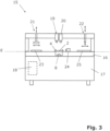
- the bonding device comprises a worktop extending along a working plane and a base supporting this worktop.
- the worktop and base can be designed in a variety of ways, but should be stable and low-vibration to enable precise bonding of the first and second components.
- the bonding device comprises a carrier plate, which is arranged on the worktop or can be arranged on the worktop and is designed according to the above description.
- the carrier plate is preferably held in a plate holding frame.
- the first component can be placed on the carrier plate. This is done by means of a handling unit designed to pick up, move, hold, and place the components.
- the component is preferably held by the handling unit in a component holding frame.
- a movable dosing valve of the bonding device is designed to apply adhesive to the first component.
- the dosing valve should be movable at least in the working plane, preferably also perpendicular to the working plane, so that adhesive can be applied to predetermined locations on the first component. After the adhesive has been applied, the second component, picked up by the handling unit or another handling unit, is placed on the first component and held parallel to the first component at a predetermined distance.
- the bonding device also has a light source for exposing the adhesive applied to the first component to light.
- the bonding device is characterized in that the light reaches the adhesive from the side of the carrier plate facing away from the components, through the carrier plate, and through the first component. This means that the light is introduced from below the carrier plate. Exposure to light cures the adhesive and creates an adhesive bond between the first and second components, with the first and second components being arranged parallel to one another and at a predetermined distance from one another.
- the components can be held in the specified position and at a predetermined distance from one another from the side of the carrier plate facing the components, without being affected by the light source. Furthermore, the light exposure allows the adhesive to cure without introducing stress into the components.
- the bonding device comprises a camera device for measuring the positions of the components. Using this camera device and preferably image processing software, the position of the first component and then the position of the second component are determined. Based on these positions, the second component is then adjusted with respect to the first component such that the relative positions correspond to the specified relative positions.
- the bonding device has sensors, in particular optical sensors, for measuring the distance between the first component and the second component.
- the handling unit holds the second component via the component holding frame.
- the sensors are directed, for example, at one or preferably several points on the edges of the first and second components and measure the distance between the components, e.g. using image processing software. Based on the measured distance, the handling unit holding the second component is controlled such that the predetermined distance is achieved. Differences between the distances measured at different points on the edges show that the second component is not yet held parallel to the first component and preferably lead to a correction by the handling unit.
- the light source is a UV light source and/or a laser.
- UV light refers to light with wavelengths in the range of 100 nm to 380 nm. The exact wavelength of the required UV light depends on the adhesive used. Using a laser to expose the adhesive to light makes it possible to achieve particularly high light intensities and, thus, achieve particularly rapid curing of the adhesive.
- Figure 1a shows a schematic cross-section through a carrier plate 2 held in a plate holding frame 1 for establishing an adhesive connection between at least a first and a second, at least partially transparent plate-shaped component.
- the position and orientation of the carrier plate 2 can be adjusted, for example, via the plate holding frame 1.
- the carrier plate 2 has a transparent, i.e., translucent, base body 3.
- the base body 3 is plate-shaped, i.e., it is a cuboid whose height is much smaller than its length and width.
- Raised structures 4 are arranged on the upper side of the base body 3 of the carrier plate 2, onto which the first component is placed.
- the raised structures 4 are produced, for example, using an etching process.
- a protective layer such as a chrome layer, is applied to the locations where the raised structures 4 are to be located. Then, sufficient material is etched away from the unprotected areas until the height of the raised structures 4 above the base body 3 reaches a predetermined value. The protective layer is then removed again.
- the non-transparent sections 6 can also be formed by a mask, in particular a metal mask, connected to the base body 3. The mask is then produced in a separate manufacturing process and then connected to the base body 3 of the carrier plate 2 in a form-fitting, force-fitting and/or material-fitting manner.
- a light source 8 is arranged below the carrier plate 2, i.e., on the side of the carrier plate 2 facing away from the raised structures 4.
- the light source 8 can also be arranged at a different location, and optical elements such as mirrors or optical waveguides can be provided to direct the light from the light source 8 to the underside of the carrier plate 2.
- light source 8 Since the light from light source 8 serves to cure an adhesive applied between the first and second components, light source 8 is designed as a UV light source. UV light refers to light with wavelengths in the range from 100 nm to 380 nm. The exact spectrum of light source 8 depends on the adhesive used, since different wavelengths of light are required to cure the adhesive, depending on the adhesive.
- Figure 1b shows a cross-section through the carrier plate 2 after the first at least partially transparent plate-shaped component 9 has been placed by a handling unit onto the raised structures 4 of the carrier plate 2.
- the first component 9 can in particular be a glass plate.
- the fact that the first component 9 rests only on the raised structures 4 of the carrier plate 2 ensures a stable, largely wobble-free position of the first component 9. Forces acting on the first component 9 also only occur in the area of the raised structures 4, so that the first component 9 is largely free of stress at all other points.
- adhesive 10 is applied to the side of the first component 9 facing away from the carrier plate 2 using a dosing valve.
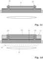
- the carrier plate 2 with the first component 9 and the applied adhesive 10 is in Figure 1c shown.
- the second at least partially transparent plate-shaped component 12 held in a component holding frame 11 is placed onto the first component 9 by a handling unit and held parallel to the first component 9 at a predetermined distance D.
- the second component 12 also comes into contact with the adhesive 10.
- the areas of the first component 9 and second component 12 where no adhesive 10 is applied are not exposed to light 13. Consequently, at the areas where no adhesive 10 is applied, the components 9 and 12 are not heated or damaged by the light 13. This also reduces stresses in the components 9 and 12 to a necessary minimum, so that the first component 9 and the second component 12 have a high degree of parallelism to one another. This is of great importance, for example, when the first and second components 9 and 12 are glass plates that are glued together parallel to one another at a predetermined distance D for use in holographic glasses.
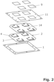
- Figure 2 shows a schematic exploded view of some of the parts used to create the adhesive bond. From bottom to top, this is the plate holding frame 1, in which the carrier plate 2 is held and by means of which the carrier plate 2 can be adjusted.
- the carrier plate 2 has raised structures 4, wherein raised structures 4 are provided for holding four first components 9, so that four adhesive bonds can be established simultaneously.
- the raised structures 4 are arranged such that they each come into contact with the first component 9 in an edge region of the first component 9.
- the mask 14 is opaque and has recesses that coincide with the raised structures 4 of the carrier plate 2. Through these recesses, the adhesive 11 can be exposed to light 13 from below through the carrier plate 2 and the first component 9.
- the component holding frame 11 in which first the first component 9 and then the second component 12 are received, has recesses for holding four first and second components 9 and 12, respectively, so that a handling unit moving the component holding frame 11 can position four components 9 or 12 simultaneously.
- first plate-shaped components 9 are shown, for which an adhesive connection can be made at the same time.
- the four second plate-shaped components 12 are preferably identical or similar to the first components 9.
Landscapes
- Engineering & Computer Science (AREA)
- Mechanical Engineering (AREA)
- Physics & Mathematics (AREA)
- Electromagnetism (AREA)
- Health & Medical Sciences (AREA)
- Toxicology (AREA)
- Chemical & Material Sciences (AREA)
- Chemical Kinetics & Catalysis (AREA)
- General Chemical & Material Sciences (AREA)
- Plasma & Fusion (AREA)
- Thermal Sciences (AREA)
- Mounting And Adjusting Of Optical Elements (AREA)
- Adhesives Or Adhesive Processes (AREA)
Claims (15)
- Procédé de fabrication d'une liaison adhésive entre au moins un premier et un deuxième composant (9 ; 12) en forme de plaques au moins partiellement transparents, dans lequel le premier composant (9) est posé sur une plaque de support (2), dans lequel une colle (10) est appliquée sur le premier composant (9) à des endroits prédéfinis sur le côté du premier composant (9) opposé à la plaque de support (2), dans lequel le deuxième composant (12) est posé sur le premier composant (9) et maintenu parallèlement au premier composant (9) à une distance prédéterminée (D), et notamment de manière à ce que le deuxième composant (12) vienne en contact avec la colle (10) située sur le premier composant (9), dans lequel, pour le durcissement de la colle (10), celle-ci est exposé à de la lumière (13) à travers la plaque de support (2) au moins partiellement transparente et à travers le premier composant (9) depuis le côté de la plaque de support (2) opposé aux composants (9 ; 12), caractérisé en ce que le premier composant (9) est posé sur des structures en relief (4) de la plaque de support (2).
- Procédé selon la revendication 1, caractérisé en ce que la plaque de support (2) est maintenue dans un cadre de maintien de plaque (1).
- Procédé selon la revendication 1 ou 2, caractérisé en ce que la colle (10) est appliquée sur le premier composant (9) au moyen d'une soupape de dosage (22).
- Procédé selon l'une des revendications 1 à 3, caractérisé en ce que les endroits prédéfinis auxquels la colle (10) est appliquée sur le premier composant (9) se trouvent dans une région de bord du premier composant (9) et/ou en ce que la colle (10) est appliquée sur le premier composant (9) dans la région des structures en relief (4) de la plaque de support (2) et/ou en ce qu'au moins le deuxième composant (12) est maintenu par une unité de manipulation (21) dans un cadre de maintien de composant (11).
- Procédé selon l'une des revendications 1 à 4, caractérisé en ce qu'après la pose du premier composant (9) sur la plaque de support (2), la position du premier composant (9) est mesurée au moyen d'un dispositif de caméra (19), avant la mise en contact du deuxième composant (12) avec la colle (10), la position du deuxième composant (12) est mesurée au moyen du dispositif de caméra (19) et le deuxième composant (12) est ajusté par rapport au premier composant (9) sur la base des positions mesurées.
- Procédé selon la revendication 4 ou 5, caractérisé en ce que l'unité de manipulation (21) maintenant le cadre de maintien de composant (11) est orientée parallèlement à la plaque de support (2), dans lequel l'orientation est effectuée manuellement de façon optique et/ou au moyen de capteurs.
- Procédé selon l'une des revendications 1 à 6, caractérisé en ce que le maintien du deuxième composant (12) à un distance prédéterminée (D) du premier composant (9) est effectué au moyen d'espaceurs fixés au premier composant (9) et/ou posés sur le premier composant (9) et/ou en ce que le maintien du deuxième composant (12) à une distance prédéterminée (D) du premier composant (9) est effectué au moyen de capteurs (24), en particulier de capteurs optiques.
- Procédé selon l'une des revendications 1 à 7, caractérisé en ce que la lumière (13) appliquée à la colle (10) est fournie par une source de lumière UV et/ou par un laser et/ou en ce que la lumière (13) est bloquée par des sections non transparentes (6) de la plaque de support (2), de telle façon que seules les régions du premier et du deuxième composant (9 ; 12) où la colle (10) est appliquée sont soumises à de la lumière (13).
- Procédé selon l'une des revendications 1 à 8, caractérisé en ce que de façon analogique à la fabrication de la liaison adhésive entre le premier composant (9) et le deuxième composant (12), une liaison adhésive est fabriquée entre le deuxième composant (12) et un autre composant et cette étape de procédé est répétée le cas échéant pour encore d'autres composants.
- Plaque de support destinée à la fabrication d'une liaison adhésive entre au moins un premier et un deuxième composant (9 ; 12) en forme de plaques au moins partiellement transparents conformément au procédé selon l'une des revendications 1 à 9, présentant un corps de base (3) avec des structures en relief (4) sur lesquelles le premier composant (9) peut être posé, dans laquelle la plaque de support (2) présente au moins une section transparente (7) et au moins une section non transparente (6), caractérisée en ce que les sections transparentes (7) sont disposées dans la région des structures en relief (4).
- Plaque de support selon la revendication 10, caractérisée en ce que les structures en relief (4) sont réalisées par attaque chimique des endroits non en relief.
- Plaque de support selon la revendication 10 ou 11, caractérisée en ce que les sections non transparentes (6) sont formées par une couche opaque (5) appliquée sur le corps de base (3), en particulier une couche de chrome, et/ou en ce que les sections non transparentes (6) sont formées par un masque (14) relié au corps de base (3), en particulier un masque métallique, et/ou en ce que la transparence et l'opacité se rapportent à la lumière UV.
- Dispositif de collage destiné à fabriquer une liaison adhésive entre au moins un premier et un deuxième composant (9 ; 12) en forme de plaques au moins partiellement transparents conformément au procédé selon l'une des revendications 1 à 9, présentant une plaque de travail (16) s'étendant le long d'un plan de travail et un châssis (17) portant ladite plaque de travail (16), une plaque de support (2) selon l'une des revendications 15 à 20, disposée ou apte à être disposée sur la plaque de travail (16), sur laquelle le premier composant (9) peut être posé, une unité de manipulation (21) permettant de recevoir, déplacer, maintenir et déposer les composants (9 ; 12), une soupape de dosage déplaçable (22) pour l'application d'une colle (10) sur le premier composant (9) et une source de lumière (8) permettant d'exposer la colle (10) appliquée sur le premier composant (9) à de la lumière (13) à travers la plaque de support (2) et à travers le premier composant (9) depuis le côté de la plaque de support (2) opposé aux composants (9 ; 12).
- Dispositif de collage selon la revendication 13, caractérisé en ce que le dispositif de collage (15) présente un dispositif de caméra (19) destiné à mesurer les positions des composants (9 ; 12) et/ou en ce que le dispositif de collage (15) présente des capteurs (24) destinés à mesurer la distance (D) entre le premier composant (9) et le deuxième composant (12).
- Dispositif de collage selon les revendications 13 à 14, caractérisé en ce que la source de lumière (8) est une source de lumière UV et/ou un laser.
Applications Claiming Priority (2)
| Application Number | Priority Date | Filing Date | Title |
|---|---|---|---|
| DE102019120954.4A DE102019120954B4 (de) | 2019-08-02 | 2019-08-02 | Verfahren zur Herstellung einer Klebeverbindung, Trägerplatte für die Herstellung einer Klebeverbindung und Klebevorrichtung zur Herstellung einer Klebeverbindung |
| PCT/EP2020/071364 WO2021023592A1 (fr) | 2019-08-02 | 2020-07-29 | Procédé de production d'un joint collé et plaque de support pour produire un joint collé |
Publications (3)
| Publication Number | Publication Date |
|---|---|
| EP4007700A1 EP4007700A1 (fr) | 2022-06-08 |
| EP4007700C0 EP4007700C0 (fr) | 2025-07-02 |
| EP4007700B1 true EP4007700B1 (fr) | 2025-07-02 |
Family
ID=71948557
Family Applications (1)
| Application Number | Title | Priority Date | Filing Date |
|---|---|---|---|
| EP20751100.7A Active EP4007700B1 (fr) | 2019-08-02 | 2020-07-29 | Procédé de production d'un joint collé et plaque de support pour produire un joint collé |
Country Status (5)
| Country | Link |
|---|---|
| US (1) | US11752701B2 (fr) |
| EP (1) | EP4007700B1 (fr) |
| CN (1) | CN114450160B (fr) |
| DE (1) | DE102019120954B4 (fr) |
| WO (1) | WO2021023592A1 (fr) |
Families Citing this family (1)
| Publication number | Priority date | Publication date | Assignee | Title |
|---|---|---|---|---|
| CN115128102B (zh) * | 2022-06-30 | 2022-12-16 | 江阴瑞兴塑料玻璃制品有限公司 | 非熔化法玻璃结合鉴定平台及方法 |
Family Cites Families (13)
| Publication number | Priority date | Publication date | Assignee | Title |
|---|---|---|---|---|
| US5433810A (en) | 1992-09-16 | 1995-07-18 | Abrams; Herbert M. | Lamination of composite eyeglass lenses |
| US6524433B2 (en) * | 1998-05-11 | 2003-02-25 | Theodore J. Sweeney, Jr. | Self-dispensing fastener for photocuring adhesive |
| JP2004086010A (ja) * | 2002-08-28 | 2004-03-18 | Sharp Corp | 表示素子製造装置および表示素子の製造方法 |
| DE10394243B4 (de) | 2003-06-02 | 2015-10-29 | Amicra Microtechnologies Gmbh | Bondvorrichtung und Bondverfahren |
| JP2006168252A (ja) * | 2004-12-17 | 2006-06-29 | Koito Mfg Co Ltd | 光線溶着装置及び光線溶着方法 |
| DE102006001885B4 (de) | 2006-01-13 | 2010-03-04 | Siemens Ag | Detektormodul eines Detektors und Verwendung eines Schmelzklebstoffes zur Herstellung eines Detektormoduls |
| JP5784903B2 (ja) * | 2010-12-22 | 2015-09-24 | デクセリアルズ株式会社 | 板状接合体の製造方法及び板状体の接合装置 |
| JP5798750B2 (ja) | 2011-01-24 | 2015-10-21 | 芝浦メカトロニクス株式会社 | 接着剤供給装置及び接着剤供給方法 |
| JP2014139297A (ja) | 2012-12-21 | 2014-07-31 | Asahi Glass Co Ltd | 粘着層付き透明面材、表示装置およびそれらの製造方法 |
| DE102015112909B3 (de) * | 2015-08-05 | 2017-02-09 | Leonhard Kurz Stiftung & Co. Kg | Verfahren und Vorrichtung zum Herstellen einer Mehrschichtfolie |
| TWI764875B (zh) * | 2015-11-03 | 2022-05-21 | 德商利昂哈德 庫爾茲公司 | 用於將薄膜上的轉印層施覆在底材上的方法及其施覆裝置 |
| EP3452267B1 (fr) * | 2016-05-03 | 2022-03-16 | Precision Valve & Automation, Inc. | Machine de liaison optique présentant un durcissement en place et un retour visuel |
| DE102017105935B4 (de) * | 2017-03-20 | 2021-09-02 | Preh Gmbh | Verfahren zum vollflächigen Verbinden von antiparallel verlaufenden Kontaktflächen eines ersten und zweiten Fügepartners mittels eines Formlings |
-
2019
- 2019-08-02 DE DE102019120954.4A patent/DE102019120954B4/de active Active
-
2020
- 2020-07-29 US US17/597,913 patent/US11752701B2/en active Active
- 2020-07-29 EP EP20751100.7A patent/EP4007700B1/fr active Active
- 2020-07-29 CN CN202080063655.7A patent/CN114450160B/zh active Active
- 2020-07-29 WO PCT/EP2020/071364 patent/WO2021023592A1/fr not_active Ceased
Also Published As
| Publication number | Publication date |
|---|---|
| US11752701B2 (en) | 2023-09-12 |
| US20220274348A1 (en) | 2022-09-01 |
| DE102019120954A1 (de) | 2021-02-04 |
| EP4007700C0 (fr) | 2025-07-02 |
| DE102019120954B4 (de) | 2023-02-02 |
| WO2021023592A1 (fr) | 2021-02-11 |
| EP4007700A1 (fr) | 2022-06-08 |
| CN114450160A (zh) | 2022-05-06 |
| CN114450160B (zh) | 2024-03-08 |
Similar Documents
| Publication | Publication Date | Title |
|---|---|---|
| EP1112802B1 (fr) | Procédé et dispositif pour chauffer au moins deux éléments par rayon laser à haute densité d'énergie | |
| EP3596750B1 (fr) | Procédé d'assemblage d'au moins trois substrats | |
| WO2008006504A2 (fr) | Procédé de fabrication de composants optoélectroniques et produits fabriqués à l'aide desdits composants | |
| EP3282181A1 (fr) | Lentille micro-optique sur verre présentant un conception de protection et procédé de fabrication | |
| DE19644758A1 (de) | Zentrieranordnung zum Positionieren von mikrostrukturierten Körpern | |
| DE3211867A1 (de) | Verfahren und vorrichtung zum justieren und montieren von optischen bauteilen in optischen geraeten | |
| EP0614539A1 (fr) | Procede de fabrication d'un couvercle pour un circuit optique integre | |
| DE102017210994A1 (de) | Messsystem für eine Vorrichtung zum generativen Herstellen eines dreidimensionalen Objekts | |
| DE3138296A1 (de) | Verfahren zum positionieren und fixieren von optischen bauelementen relativ zueinander | |
| EP0922983A1 (fr) | Technique de connexion pour des lentilles et des montures résistantes aux rayons VUV | |
| EP1564804B1 (fr) | Un appareil et un procédé pour joindre des wafers | |
| DE19546443A1 (de) | Optische und/oder elektrooptische Verbindung und Verfahren zur Herstellung einer solchen | |
| DE19901623B4 (de) | Verfahren und Vorrichtung zur thermischen Verbindung von Anschlußflächen zweier Substrate | |
| DE102007022895B9 (de) | Vorrichtung zum Übertragen von in einer Maske vorgesehenen Strukturen auf ein Substrat | |
| DE102019120954B4 (de) | Verfahren zur Herstellung einer Klebeverbindung, Trägerplatte für die Herstellung einer Klebeverbindung und Klebevorrichtung zur Herstellung einer Klebeverbindung | |
| DE4411860C2 (de) | Verfahren zur Herstellung von dreidimensionalen Wellenleiterstrukturen | |
| DE4240950C1 (de) | Verfahren zum Herstellen eines Deckels für eine integriert optische Schaltung und Deckel für eine integriert optische Schaltung | |
| EP2855131B1 (fr) | Procédé et dispositif de fabrication d'une pluralité de microlentilles | |
| DE102017210379A1 (de) | Bildsensormodul | |
| DE19819054B4 (de) | Verfahren und Vorrichtung zur Montage und Justierung von Bauteilen auf einer Befestigungsunterlage | |
| EP4061566B1 (fr) | Appareil de fabrication additive par un procédé de couche de poudre | |
| WO2024002691A1 (fr) | Dispositif et procédé pour établir une connexion de contact | |
| DE4117449C1 (fr) | ||
| DE102022117495B4 (de) | Verfahren und Vorrichtung zum Anordnen von optischen Elementen an ein Substrat mit einer Mehrzahl von optoelektronischen Bauelementen | |
| WO2000002247A1 (fr) | Procede et dispositif pour la fabrication d'un composite entre un corps porteur et au moins un composant contenu a l'interieur |
Legal Events
| Date | Code | Title | Description |
|---|---|---|---|
| STAA | Information on the status of an ep patent application or granted ep patent |
Free format text: STATUS: UNKNOWN |
|
| STAA | Information on the status of an ep patent application or granted ep patent |
Free format text: STATUS: THE INTERNATIONAL PUBLICATION HAS BEEN MADE |
|
| PUAI | Public reference made under article 153(3) epc to a published international application that has entered the european phase |
Free format text: ORIGINAL CODE: 0009012 |
|
| STAA | Information on the status of an ep patent application or granted ep patent |
Free format text: STATUS: REQUEST FOR EXAMINATION WAS MADE |
|
| 17P | Request for examination filed |
Effective date: 20220215 |
|
| AK | Designated contracting states |
Kind code of ref document: A1 Designated state(s): AL AT BE BG CH CY CZ DE DK EE ES FI FR GB GR HR HU IE IS IT LI LT LU LV MC MK MT NL NO PL PT RO RS SE SI SK SM TR |
|
| RAP3 | Party data changed (applicant data changed or rights of an application transferred) |
Owner name: ASMPT AMICRA GMBH |
|
| DAV | Request for validation of the european patent (deleted) | ||
| DAX | Request for extension of the european patent (deleted) | ||
| STAA | Information on the status of an ep patent application or granted ep patent |
Free format text: STATUS: EXAMINATION IS IN PROGRESS |
|
| 17Q | First examination report despatched |
Effective date: 20230207 |
|
| GRAP | Despatch of communication of intention to grant a patent |
Free format text: ORIGINAL CODE: EPIDOSNIGR1 |
|
| STAA | Information on the status of an ep patent application or granted ep patent |
Free format text: STATUS: GRANT OF PATENT IS INTENDED |
|
| INTG | Intention to grant announced |
Effective date: 20250423 |
|
| GRAS | Grant fee paid |
Free format text: ORIGINAL CODE: EPIDOSNIGR3 |
|
| GRAA | (expected) grant |
Free format text: ORIGINAL CODE: 0009210 |
|
| STAA | Information on the status of an ep patent application or granted ep patent |
Free format text: STATUS: THE PATENT HAS BEEN GRANTED |
|
| AK | Designated contracting states |
Kind code of ref document: B1 Designated state(s): AL AT BE BG CH CY CZ DE DK EE ES FI FR GB GR HR HU IE IS IT LI LT LU LV MC MK MT NL NO PL PT RO RS SE SI SK SM TR |
|
| REG | Reference to a national code |
Ref country code: GB Ref legal event code: FG4D Free format text: NOT ENGLISH |
|
| REG | Reference to a national code |
Ref country code: CH Ref legal event code: EP |
|
| REG | Reference to a national code |
Ref country code: DE Ref legal event code: R096 Ref document number: 502020011346 Country of ref document: DE |
|
| REG | Reference to a national code |
Ref country code: IE Ref legal event code: FG4D Free format text: LANGUAGE OF EP DOCUMENT: GERMAN |
|
| U01 | Request for unitary effect filed |
Effective date: 20250728 |
|
| U07 | Unitary effect registered |
Designated state(s): AT BE BG DE DK EE FI FR IT LT LU LV MT NL PT RO SE SI Effective date: 20250801 |
|
| U20 | Renewal fee for the european patent with unitary effect paid |
Year of fee payment: 6 Effective date: 20250731 |
|
| PG25 | Lapsed in a contracting state [announced via postgrant information from national office to epo] |
Ref country code: IS Free format text: LAPSE BECAUSE OF FAILURE TO SUBMIT A TRANSLATION OF THE DESCRIPTION OR TO PAY THE FEE WITHIN THE PRESCRIBED TIME-LIMIT Effective date: 20251102 |
|
| PG25 | Lapsed in a contracting state [announced via postgrant information from national office to epo] |
Ref country code: NO Free format text: LAPSE BECAUSE OF FAILURE TO SUBMIT A TRANSLATION OF THE DESCRIPTION OR TO PAY THE FEE WITHIN THE PRESCRIBED TIME-LIMIT Effective date: 20251002 |
|
| PG25 | Lapsed in a contracting state [announced via postgrant information from national office to epo] |
Ref country code: HR Free format text: LAPSE BECAUSE OF FAILURE TO SUBMIT A TRANSLATION OF THE DESCRIPTION OR TO PAY THE FEE WITHIN THE PRESCRIBED TIME-LIMIT Effective date: 20250702 |
|
| PG25 | Lapsed in a contracting state [announced via postgrant information from national office to epo] |
Ref country code: GR Free format text: LAPSE BECAUSE OF FAILURE TO SUBMIT A TRANSLATION OF THE DESCRIPTION OR TO PAY THE FEE WITHIN THE PRESCRIBED TIME-LIMIT Effective date: 20251003 |
|
| PG25 | Lapsed in a contracting state [announced via postgrant information from national office to epo] |
Ref country code: CZ Free format text: LAPSE BECAUSE OF FAILURE TO SUBMIT A TRANSLATION OF THE DESCRIPTION OR TO PAY THE FEE WITHIN THE PRESCRIBED TIME-LIMIT Effective date: 20250702 |
|
| PG25 | Lapsed in a contracting state [announced via postgrant information from national office to epo] |
Ref country code: PL Free format text: LAPSE BECAUSE OF FAILURE TO SUBMIT A TRANSLATION OF THE DESCRIPTION OR TO PAY THE FEE WITHIN THE PRESCRIBED TIME-LIMIT Effective date: 20250702 |
|
| PG25 | Lapsed in a contracting state [announced via postgrant information from national office to epo] |
Ref country code: RS Free format text: LAPSE BECAUSE OF FAILURE TO SUBMIT A TRANSLATION OF THE DESCRIPTION OR TO PAY THE FEE WITHIN THE PRESCRIBED TIME-LIMIT Effective date: 20251002 |
|
| PG25 | Lapsed in a contracting state [announced via postgrant information from national office to epo] |
Ref country code: ES Free format text: LAPSE BECAUSE OF FAILURE TO SUBMIT A TRANSLATION OF THE DESCRIPTION OR TO PAY THE FEE WITHIN THE PRESCRIBED TIME-LIMIT Effective date: 20250702 |
|
| REG | Reference to a national code |
Ref country code: CH Ref legal event code: H13 Free format text: ST27 STATUS EVENT CODE: U-0-0-H10-H13 (AS PROVIDED BY THE NATIONAL OFFICE) Effective date: 20260224 |
|
| PG25 | Lapsed in a contracting state [announced via postgrant information from national office to epo] |
Ref country code: SM Free format text: LAPSE BECAUSE OF FAILURE TO SUBMIT A TRANSLATION OF THE DESCRIPTION OR TO PAY THE FEE WITHIN THE PRESCRIBED TIME-LIMIT Effective date: 20250702 |
|
| PG25 | Lapsed in a contracting state [announced via postgrant information from national office to epo] |
Ref country code: CH Free format text: LAPSE BECAUSE OF NON-PAYMENT OF DUE FEES Effective date: 20250731 |
|
| PG25 | Lapsed in a contracting state [announced via postgrant information from national office to epo] |
Ref country code: SK Free format text: LAPSE BECAUSE OF FAILURE TO SUBMIT A TRANSLATION OF THE DESCRIPTION OR TO PAY THE FEE WITHIN THE PRESCRIBED TIME-LIMIT Effective date: 20250702 |
|
| PLBE | No opposition filed within time limit |
Free format text: ORIGINAL CODE: 0009261 |
|
| STAA | Information on the status of an ep patent application or granted ep patent |
Free format text: STATUS: NO OPPOSITION FILED WITHIN TIME LIMIT |
|
| REG | Reference to a national code |
Ref country code: CH Ref legal event code: L10 Free format text: ST27 STATUS EVENT CODE: U-0-0-L10-L00 (AS PROVIDED BY THE NATIONAL OFFICE) Effective date: 20260518 |
|
| 26N | No opposition filed |
Effective date: 20260407 |
|
| GBPC | Gb: european patent ceased through non-payment of renewal fee |
Effective date: 20251002 |
|
| PG25 | Lapsed in a contracting state [announced via postgrant information from national office to epo] |
Ref country code: MC Free format text: LAPSE BECAUSE OF FAILURE TO SUBMIT A TRANSLATION OF THE DESCRIPTION OR TO PAY THE FEE WITHIN THE PRESCRIBED TIME-LIMIT Effective date: 20250702 |
|
| PG25 | Lapsed in a contracting state [announced via postgrant information from national office to epo] |
Ref country code: GB Free format text: LAPSE BECAUSE OF NON-PAYMENT OF DUE FEES Effective date: 20251002 |
|
| PG25 | Lapsed in a contracting state [announced via postgrant information from national office to epo] |
Ref country code: IE Free format text: LAPSE BECAUSE OF NON-PAYMENT OF DUE FEES Effective date: 20250729 |
|
| PG25 | Lapsed in a contracting state [announced via postgrant information from national office to epo] |
Ref country code: CY Free format text: LAPSE BECAUSE OF FAILURE TO SUBMIT A TRANSLATION OF THE DESCRIPTION OR TO PAY THE FEE WITHIN THE PRESCRIBED TIME-LIMIT Effective date: 20250702 |