EP4007739B1 - Appareil de lampe à ultraviolets anti-vibration à extrémité unique - Google Patents
Appareil de lampe à ultraviolets anti-vibration à extrémité unique Download PDFInfo
- Publication number
- EP4007739B1 EP4007739B1 EP20751650.1A EP20751650A EP4007739B1 EP 4007739 B1 EP4007739 B1 EP 4007739B1 EP 20751650 A EP20751650 A EP 20751650A EP 4007739 B1 EP4007739 B1 EP 4007739B1
- Authority
- EP
- European Patent Office
- Prior art keywords
- lamp
- end cap
- water
- lamps
- reactor
- Prior art date
- Legal status (The legal status is an assumption and is not a legal conclusion. Google has not performed a legal analysis and makes no representation as to the accuracy of the status listed.)
- Active
Links
Images



Classifications
-
- C—CHEMISTRY; METALLURGY
- C02—TREATMENT OF WATER, WASTE WATER, SEWAGE, OR SLUDGE
- C02F—TREATMENT OF WATER, WASTE WATER, SEWAGE, OR SLUDGE
- C02F1/00—Treatment of water, waste water, or sewage
- C02F1/30—Treatment of water, waste water, or sewage by irradiation
- C02F1/32—Treatment of water, waste water, or sewage by irradiation with ultraviolet light
- C02F1/325—Irradiation devices or lamp constructions
-
- A—HUMAN NECESSITIES
- A61—MEDICAL OR VETERINARY SCIENCE; HYGIENE
- A61L—METHODS OR APPARATUS FOR STERILISING MATERIALS OR OBJECTS IN GENERAL; DISINFECTION, STERILISATION OR DEODORISATION OF AIR; CHEMICAL ASPECTS OF BANDAGES, DRESSINGS, ABSORBENT PADS OR SURGICAL ARTICLES; MATERIALS FOR BANDAGES, DRESSINGS, ABSORBENT PADS OR SURGICAL ARTICLES
- A61L2/00—Disinfection or sterilisation of materials or objects, in general; Accessories therefor
- A61L2/02—Disinfection or sterilisation of materials or objects, in general; Accessories therefor using physical processes
- A61L2/08—Radiation
- A61L2/10—Ultraviolet [UV] radiation
-
- C—CHEMISTRY; METALLURGY
- C02—TREATMENT OF WATER, WASTE WATER, SEWAGE, OR SLUDGE
- C02F—TREATMENT OF WATER, WASTE WATER, SEWAGE, OR SLUDGE
- C02F1/00—Treatment of water, waste water, or sewage
- C02F1/72—Treatment of water, waste water, or sewage by oxidation
-
- C—CHEMISTRY; METALLURGY
- C02—TREATMENT OF WATER, WASTE WATER, SEWAGE, OR SLUDGE
- C02F—TREATMENT OF WATER, WASTE WATER, SEWAGE, OR SLUDGE
- C02F2101/00—Nature of the contaminant
- C02F2101/30—Organic compounds
-
- C—CHEMISTRY; METALLURGY
- C02—TREATMENT OF WATER, WASTE WATER, SEWAGE, OR SLUDGE
- C02F—TREATMENT OF WATER, WASTE WATER, SEWAGE, OR SLUDGE
- C02F2103/00—Nature of the water, waste water, sewage or sludge to be treated
- C02F2103/06—Contaminated groundwater or leachate
-
- C—CHEMISTRY; METALLURGY
- C02—TREATMENT OF WATER, WASTE WATER, SEWAGE, OR SLUDGE
- C02F—TREATMENT OF WATER, WASTE WATER, SEWAGE, OR SLUDGE
- C02F2201/00—Apparatus for treatment of water, waste water or sewage
- C02F2201/32—Details relating to UV-irradiation devices
- C02F2201/322—Lamp arrangement
- C02F2201/3223—Single elongated lamp located on the central axis of a turbular reactor
-
- C—CHEMISTRY; METALLURGY
- C02—TREATMENT OF WATER, WASTE WATER, SEWAGE, OR SLUDGE
- C02F—TREATMENT OF WATER, WASTE WATER, SEWAGE, OR SLUDGE
- C02F2201/00—Apparatus for treatment of water, waste water or sewage
- C02F2201/32—Details relating to UV-irradiation devices
- C02F2201/322—Lamp arrangement
- C02F2201/3227—Units with two or more lamps
-
- C—CHEMISTRY; METALLURGY
- C02—TREATMENT OF WATER, WASTE WATER, SEWAGE, OR SLUDGE
- C02F—TREATMENT OF WATER, WASTE WATER, SEWAGE, OR SLUDGE
- C02F2201/00—Apparatus for treatment of water, waste water or sewage
- C02F2201/32—Details relating to UV-irradiation devices
- C02F2201/322—Lamp arrangement
- C02F2201/3228—Units having reflectors, e.g. coatings, baffles, plates, mirrors
-
- C—CHEMISTRY; METALLURGY
- C02—TREATMENT OF WATER, WASTE WATER, SEWAGE, OR SLUDGE
- C02F—TREATMENT OF WATER, WASTE WATER, SEWAGE, OR SLUDGE
- C02F2201/00—Apparatus for treatment of water, waste water or sewage
- C02F2201/32—Details relating to UV-irradiation devices
- C02F2201/326—Lamp control systems
-
- C—CHEMISTRY; METALLURGY
- C02—TREATMENT OF WATER, WASTE WATER, SEWAGE, OR SLUDGE
- C02F—TREATMENT OF WATER, WASTE WATER, SEWAGE, OR SLUDGE
- C02F2303/00—Specific treatment goals
- C02F2303/04—Disinfection
-
- C—CHEMISTRY; METALLURGY
- C02—TREATMENT OF WATER, WASTE WATER, SEWAGE, OR SLUDGE
- C02F—TREATMENT OF WATER, WASTE WATER, SEWAGE, OR SLUDGE
- C02F2305/00—Use of specific compounds during water treatment
- C02F2305/02—Specific form of oxidant
- C02F2305/023—Reactive oxygen species, singlet oxygen, OH radical
Definitions
- a UV apparatus normally comprises a housing, a quartz tube and a UV lamp that fits inside the quartz tube.
- the quartz tube separates the liquid to be treated from the UV lamp.
- the UV lamp has electrical connections that are connected to a power supply. As a liquid is passed through the housing, it is irradiated by UV light to photochemically destroy bacteria and/or organic compounds.
- a water treatment system as defined in claim 1 is provided.
- the thermally conductive elements comprise metallic springs.
- the metallic springs retain the electrical conductor within the slots.
- the methods and systems disclosed herein may treat contaminated wastewater to produce potable water.
- the potable water may comply with standards set by municipalities.
- the term "recalcitrant organic" when used in reference to a contaminant refers to organic compounds that resist microbial degradation or are not readily biodegradable. In certain instances, the recalcitrant organic contaminant may not degrade biologically, and remediation methods may be unable to remove enough of the substance to satisfy environmental regulations.
- Non-limiting examples of recalcitrant organic contaminants include 1,4-dioxane, trichloroethylene (TCE), perchloroethylene (PCE), urea, isopropanol, chloroform, atrazine, tryptophan, and formic acid.
- the methods and systems disclosed herein may include providing a contaminated wastewater having an initial concentration of a recalcitrant organic contaminant.
- the methods and systems disclosed herein may include extracting or otherwise removing the contaminated wastewater.
- the contaminated wastewater may be pumped from the ground or other sources using one or more pumps or other extraction devices as part of a remediation effort. Once treated, the wastewater may then be discharged or sent on for further processing.
- the contaminated wastewater is pumped or otherwise removed to the surface grade level where it may then be treated according to the processes and methods discussed herein.
- the methods and systems disclosed herein may include extracting the contaminated wastewater from a remediation site.
- the contaminated wastewater may have a level of total dissolved solids (TDS) that is in a range of about 100 mg/L to about 5000 mg/L, and in some instances may be in a range of about 200 mg/L to about 2000 mg/L, although these values can vary depending on the geographic location and other factors.
- TDS total dissolved solids
- water with a TDS level of 1000-1500 mg/L is considered drinkable, with some standards having a 500 mg/L TDS limit for domestic water supplies.
- the methods and systems disclosed herein may be connected or otherwise in fluid communication with a source of contaminated wastewater.
- the contaminated wastewater may be pumped or otherwise delivered to the disclosed system for treatment.
- the concentration of recalcitrant organic contaminant in the wastewater is high enough to exceed limits established by government agencies.
- the systems and methods disclosed herein treat the wastewater such that the concentration level of the recalcitrant organic contaminant is reduced.
- the systems and methods disclosed herein reduce the concentration of the recalcitrant organic contaminant to a level that complies with government standards or guidelines.
- the concentration of recalcitrant organic contaminant is reduced to a level such that the treated wastewater may be reintroduced back into the environment.
- the EPA's standard for the concentration of 1,4-dixoane in drinking water is 1 ⁇ g/L (1 ppb).
- the methods and systems disclosed herein may be scaled to treat substantially all concentrations of recalcitrant organic contaminant that may be present in the wastewater.
- the initial concentration of recalcitrant organic contaminant, such as dioxane, in the wastewater may be in a range from about 5 ppb to about 800 ppb.
- Advanced oxidation processes are a set of treatment procedures used to remove organic materials from wastewater. In many applications, these processes involve the use of UV light and hydrogen peroxide, specifically: H 2 O 2 + UV ⁇ 2 ⁇ OH (homolytic bond cleavage of the O-O bond of H 2 O 2 leads to formation of 2 ⁇ OH radicals)
- Systems disclosed herein include an actinic radiation reactor, i.e. a UV reactor, that receives one or more oxidants (e.g., H 2 O 2 , ammonium persulfate, potassium persulfate, or other persulfate species) to facilitate destruction, e.g., oxidation, of one or more contaminants in water undergoing treatment in the actinic radiation reactor.
- the actinic radiation reactor can comprise a vessel, and a first array of tubes in the vessel.
- the first array of tubes can comprise a first set of parallel tubes, and a second set of parallel tubes.
- Each tube can comprise at least one ultraviolet lamp and each of the parallel tubes of the first set is positioned to have its longitudinal axis orthogonal relative to the longitudinal axis of the tubes of the second set.
- the transmissivity can be about 80% or greater for a predetermined period of time. In certain embodiments, the transmissivity can be in a range of about 80% to 90% for about 6 months to about one year. In certain embodiments, the transmissivity can be in a range of about 80% to 90% for up to about two years.
- the point of use 345 may include a shipboard system, a drilling platform system, an aquatics system (for example, a swimming pool or a fountain), a drinking water system, or a downhole of an oil drilling system.
- the point of use 345 may include a cooling water system of a ship or sea-based platform or a ballast tank of a ship.
- the controller used for monitoring and controlling operation of the various elements of systems disclosed herein may include a computerized control system.
- Various aspects of the controller may be implemented as specialized software executing in a general-purpose computer system 400 such as that shown in FIG. 4 .
- the computer system 400 may include a processor 402 connected to one or more memory devices 404, such as a disk drive, solid state memory, or other device for storing data.
- Memory 404 is typically used for storing programs and data during operation of the computer system 400.
- Components of computer system 400 may be coupled by an interconnection mechanism 406, which may include one or more busses (e.g., between components that are integrated within a same machine) and/or a network (e.g., between components that reside on separate discrete machines).
- the storage system 412 typically includes a computer readable and writeable nonvolatile recording medium 502 in which signals are stored that define a program to be executed by the processor 402 or information to be processed by the program.
- the medium may include, for example, a disk or flash memory.
- the processor causes data to be read from the nonvolatile recording medium 502 into another memory 504 that allows for faster access to the information by the processor than does the medium 502.
- This memory 504 is typically a volatile, random access memory such as a dynamic random access memory (DRAM) or static memory (SRAM). It may be located in storage system 412, as shown, or in memory system 404.
- DRAM dynamic random access memory
- SRAM static memory
- the processor 402 generally manipulates the data within the integrated circuit memory 504 and then copies the data to the medium 502 after processing is completed.
- a variety of mechanisms are known for managing data movement between the medium 502 and the integrated circuit memory element 504, and aspects and embodiments disclosed herein are not limited thereto. Aspects and embodiments disclosed herein are not limited to a particular memory system 404 or storage system 412.
- One or more portions of the computer system may be distributed across one or more computer systems (not shown) coupled to a communications network. These computer systems also may be general-purpose computer systems. For example, various aspects of the invention may be distributed among one or more computer systems configured to provide a service (e.g., servers) to one or more client computers, or to perform an overall task as part of a distributed system. For example, various aspects and embodiments disclosed herein may be performed on a client-server system that includes components distributed among one or more server systems that perform various functions according to various aspects and embodiments disclosed herein.
- a service e.g., servers
- aspects and embodiments disclosed herein are not limited to executing on any particular system or group of systems. Also, it should be appreciated that the aspects and embodiments disclosed herein are not limited to any particular distributed architecture, network, or communication protocol.
- Various aspects and embodiments disclosed herein are may be programmed using an object-oriented programming language, such as SmallTalk, Java, C++, Ada, or C# (C-Sharp). Other object-oriented programming languages may also be used. Alternatively, functional, scripting, and/or logical programming languages may be used, for example, ladder logic.
- aspects and embodiments disclosed herein may be implemented in a non-programmed environment (e.g., documents created in HTML, XML or other format that, when viewed in a window of a browser program, render aspects of a graphical-user interface (GUI) or perform other functions).
- GUI graphical-user interface
- Various aspects and embodiments disclosed herein may be implemented as programmed or non-programmed elements, or any combination thereof.
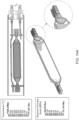
- FIG. 6 An example of a UV lamp that may be utilized in a UV AOP reactor as disclosed herein is illustrated in FIG. 6 , indicated generally at 600.
- the UV lamp 600 is a gas-discharge lamp having a sealed lamp tube 605.
- the lamp tube 605 is formed of a material that is transparent, or at least partially transparent to UV radiation, for example, quartz.
- the lamp tube 605 contains a gas that emits ultraviolet radiation when excited by electric current provided by electrodes (not shown) disposed at opposite ends within the lamp tube 605.
- the gas may include mercury vapor which may be mixed with one or more of neon, argon, and/or xenon.
- Commercially available UV lamps may be obtained from Alphacure (Northamptonshire, UK), Signify (Philips Lighting, The Netherlands), Heraeus Noblelight GmbH (Hanau, Germany), or Light Sources (LSI, Orange, CT).
- the pinches 610 include electrical conductors for bringing electrical current from external electrical connections to the electrodes within the lamp tube 605.
- the pinches 610 are mounted within and secured by an adhesive or cement, for example, ceramic adhesive paste (available from Fortafix, Hartlepool, UK) within central portions of end caps 615 disposed on opposite sides of the lamp tube 605 at distal ends of the pinches 610 opposite proximal ends of the pinches 610 which contact the lamp tube 605.
- the end caps 615 are formed of a ceramic material, for example, alumina (Al 2 O 3 ) or a mixture of primarily alumina and one or more other ceramic materials, for example, 95% Al 2 O 3 , CaO (1%), SiO 2 (2%), and MgO (2%).
- the end caps 615 may have a substantially triangular cross-section as illustrated in FIG.
- the arcuate tip portions 615A may have outer surfaces defining portions of circle.
- the end caps 615 may also be considered to include three lobes extending outward from central regions of the end caps 615 and terminating in the arcuate tip portions 6125A.
- the triangular shape of the end caps 615 may facilitate electrically connecting the UV lamp 600 to electrical connectors known in the art, for example, as disclosed in U.S. Patent No. 8,876,359 .
- the end caps 615 may be circular or any other shape that provides for the end caps 615 to fit within a quartz tube having a desired shape.
- the outer surfaces of the arcuate tip portions 6125A may be curved to match the curvature of an internal wall of a quartz tube in which the lamp tube 605 is to be disposed.
- the end caps 615 may this be considered to have portions of outer peripheral surfaces that are contoured to conform to an inner surface of the quartz tube.
- the springs 620 may be formed of coils canted at angles of, for example, about 70° relative to the surfaces of the perimeter portions of the end caps 615 to allow compression under radial load, aiding installation and reducing vibration.
- the springs 620 may be formed of a metal, for example, stainless steel.
- the springs 620 may provide for good contact between the lamp and a quartz tube in which the lamp may be installed, providing a high thermal conductivity path for heat transfer from the lamp tube 605 through the pinches 610 and end caps 615 to the quartz tube.
- FIG. 7 illustrates, in both a cross-sectional and end view, how the UV lamp may be positioned within a quartz tube 700 with the lamp tube 605 centered coaxially within the quartz tube 700 and having a central axis parallel with or overlapping a central axis of the quartz tube 700.
- the quartz tube 700 may, in use, be submerged in water undergoing treatment in a UV reactor and may transfer heat into the water undergoing treatment which acts as a heat sink for the lamp assembly and helps cool the lamp assembly.
- an existing UV AOP system may be modified or upgraded to include UV lamps as disclosed herein, for example, as illustrated in FIGS. 6 and 7 .
- a method of retrofitting a UV AOP system cell to increase the reliability of the system may include installing one or more UV lamps as disclosed herein in the UV AOP.
- FIGS. 9A-9C illustrate the results of the vibration testing of the standard lamps in the X, Y, and Z axes, respectively. In the charts of FIGS.
- the Y axis represents recorded g-forces and the X axis represents applied vibrational frequency.
- FIG. 13 illustrates the variation in temperature of the "near pinch” and the "far pinch” in the mounting configuration of FIG. 7 over a period of 30 minutes after turning on the lamp when the quartz tube was submerged in water having a temperature of about 12° C.
- the initial bump on the graph of FIG. 13 is due to the lamp being inadvertently stopped and restarted.
- FIG. 13 illustrates that with a lamp configured as disclosed herein, the pinches on both ends of the lamp tube exhibit very similar results with respect to operating temperature, with both operating at ⁇ 255° C, significantly cooler and more uniform than the standard lamps in either of the mounting configurations tested.
- FEA Finite Element Analysis
- the stress is greatly reduced in the lamp configured as disclosed herein and does not exceed tensile yield stress of the pinches.
- the heat and stress distribution of the lamp configured as disclosed herein is substantially symmetrical from one end of the lamp to the other, while the standard UV lamp exhibits substantially higher temperatures and stresses at one end as compared to the other.
- the striking current, running current, and running voltage was found for each lamp. This was repeated at the end of the test, to understand any changes that had occurred. During testing the striking current was monitored. At the end of testing, the lamp parameters were still well within the characteristic tolerances, and both lamps were still running well.
- the lamps were also visually inspected for any signs of wear/damage. Both lamps showed signs of black ends, presumably due to electrode sputtering (tungsten coating of the electrode is lost and condenses on the quartz sleeve). This is quite normal for lamps that have run a full lifetime, and is exacerbated by frequent strikes, which is how this test was run. The lamps otherwise looked in good condition, and none of the previous failure modes (e.g., pinch breakage) could be identified.
- the term “plurality” refers to two or more items or components.
- the terms “comprising,” “including,” “carrying,” “having,” “containing,” and “involving,” whether in the written description or the claims and the like, are open-ended terms, i.e., to mean “including but not limited to.” Thus, the use of such terms is meant to encompass the items listed thereafter, and equivalents thereof, as well as additional items. Only the transitional phrases “consisting of” and “consisting essentially of,” are closed or semi-closed transitional phrases, respectively, with respect to the claims.
Landscapes
- Life Sciences & Earth Sciences (AREA)
- Health & Medical Sciences (AREA)
- Organic Chemistry (AREA)
- Environmental & Geological Engineering (AREA)
- Water Supply & Treatment (AREA)
- Chemical & Material Sciences (AREA)
- Engineering & Computer Science (AREA)
- Hydrology & Water Resources (AREA)
- Toxicology (AREA)
- Epidemiology (AREA)
- Animal Behavior & Ethology (AREA)
- General Health & Medical Sciences (AREA)
- Public Health (AREA)
- Veterinary Medicine (AREA)
- Physical Water Treatments (AREA)
Claims (7)
- Un système de traitement d'eau comprenant :un réacteur à rayonnement actinique (100) ; etau moins une lampe à ultraviolets (UV) (600) disposée à l'intérieur d'un tube de quartz (700) au sein du réacteur à rayonnement actinique, l'au moins une lampe à UV (600) incluant :un tube de lampe (605) incluant un gaz qui émet de la lumière ultraviolette en réponse à une excitation électrique ;un premier pincement (610) s'étendant à partir d'une première extrémité du tube de lampe (605) et un deuxième pincement (610) s'étendant à partir d'une deuxième extrémité du tube de lampe (605) ; etun premier embout (615) couplé au premier pincement (610) et un deuxième embout (615) couplé au deuxième pincement (610), le premier embout et le deuxième embout étant dimensionnés pour centrer le tube de lampe (605) coaxialement à l'intérieur du tube de quartz (700) ;des éléments de sollicitation thermoconducteurs (620) disposés autour de périphéries externes respectives de chacun des premier embout (615) et deuxième embout (615), où les éléments de sollicitation thermoconducteurs (620) sont disposés à l'intérieur de rainures (625) définies au sein des surfaces périphériques externes du premier embout (615) et du deuxième embout (615) et circonscrivant celles-ci, et, où les premier et deuxième embouts (615) incluent chacun des fentes (630) s'étendant vers l'intérieur à partir des surfaces périphériques externes respectives ; etun conducteur électrique (635) disposé à l'intérieur des fentes (630) et configuré pour fournir une puissance au tube de lampe (605).
- Le système de la revendication 1, où les éléments de sollicitation thermoconducteurs (620) comprennent des ressorts métalliques.
- Le système de la revendication 1, où des portions des surfaces périphériques externes du premier embout (615) et du deuxième embout (615) sont profilées afin de se conformer à une surface interne du tube de quartz (700).
- Le système de la revendication 1, où les fentes (630) sont perpendiculaires aux rainures (625).
- Le système de la revendication 2, où les ressorts métalliques (620) retiennent le conducteur à l'intérieur des fentes (630).
- Le système de la revendication 1, où les éléments de sollicitation thermoconducteurs (620) sont au contact d'une surface interne du tube de quartz (700), supportent le tube de lampe (605) à l'intérieur du tube de quartz, et amortissent des vibrations passant du tube de quartz aux premier et deuxième embouts (615).
- Un procédé de traitement d'eau, le procédé comprenant :
l'introduction de l'eau dans une entrée d'un réacteur à rayonnement actinique incluant au moins une lampe à ultraviolets (UV) (600) disposée à l'intérieur d'un tube de quartz (700) au sein du réacteur à rayonnement actinique, l'au moins une lampe à UV (600) incluant :un tube de lampe (605) incluant un gaz qui émet de la lumière ultraviolette en réponse à une excitation électrique ;un premier pincement (610) s'étendant à partir d'une première extrémité du tube de lampe et un deuxième pincement (610) s'étendant à partir d'une deuxième extrémité du tube de lampe ; etun premier embout (615) couplé au premier pincement (610) et un deuxième embout (615) couplé au deuxième pincement (610), le premier embout et le deuxième embout étant dimensionnés pour centrer le tube de lampe (605) coaxialement à l'intérieur du tube de quartz (700) ;des éléments de sollicitation thermoconducteurs (620) disposés autour de périphéries externes respectives de chacun des premier embout (615) etdeuxième embout (615), où les premier et deuxième embouts (615) incluent chacun des fentes (630) s'étendant vers l'intérieur à partir de la surface périphérique externe respective ; etun conducteur électrique (635) disposé à l'intérieur de fentes (630) et configuré pour fournir une puissance au tube de lampe (605) ;l'irradiation de l'eau à l'intérieur du réacteur à rayonnement actinique avec de la lumière UV provenant de l'au moins une lampe à UV (600) afin de produire de l'eau traitée ; etle retrait de l'eau traitée du réacteur à rayonnement actinique.
Applications Claiming Priority (2)
| Application Number | Priority Date | Filing Date | Title |
|---|---|---|---|
| US201962881673P | 2019-08-01 | 2019-08-01 | |
| PCT/GB2020/051852 WO2021019256A1 (fr) | 2019-08-01 | 2020-07-31 | Appareil de lampe à ultraviolets anti-vibration à extrémité unique |
Publications (2)
| Publication Number | Publication Date |
|---|---|
| EP4007739A1 EP4007739A1 (fr) | 2022-06-08 |
| EP4007739B1 true EP4007739B1 (fr) | 2024-07-03 |
Family
ID=71950676
Family Applications (1)
| Application Number | Title | Priority Date | Filing Date |
|---|---|---|---|
| EP20751650.1A Active EP4007739B1 (fr) | 2019-08-01 | 2020-07-31 | Appareil de lampe à ultraviolets anti-vibration à extrémité unique |
Country Status (11)
| Country | Link |
|---|---|
| US (1) | US12162781B2 (fr) |
| EP (1) | EP4007739B1 (fr) |
| JP (1) | JP7455956B2 (fr) |
| KR (1) | KR20230006793A (fr) |
| CN (1) | CN114929630B (fr) |
| AU (1) | AU2020322127B2 (fr) |
| DK (1) | DK4007739T3 (fr) |
| ES (1) | ES2986158T3 (fr) |
| FI (1) | FI4007739T3 (fr) |
| PT (1) | PT4007739T (fr) |
| WO (1) | WO2021019256A1 (fr) |
Citations (1)
| Publication number | Priority date | Publication date | Assignee | Title |
|---|---|---|---|---|
| DE19838007C2 (de) * | 1998-08-21 | 2000-06-08 | Hansa Metallwerke Ag | Einrichtung zum Entkeimen von Wasser, welches eine Sanitäreinrichtung durchströmt |
Family Cites Families (13)
| Publication number | Priority date | Publication date | Assignee | Title |
|---|---|---|---|---|
| US4968489A (en) * | 1988-09-13 | 1990-11-06 | Peroxidation Systems, Inc. | UV lamp enclosure sleeve |
| US5505912A (en) * | 1992-02-18 | 1996-04-09 | Cryptonics Corporation | Lamp cooling for a UV lamp reactor assembly |
| JP3624999B2 (ja) * | 1996-10-31 | 2005-03-02 | ハリソン東芝ライティング株式会社 | 無電極放電ランプユニット及び液体処理装置 |
| JP2004181273A (ja) | 2002-11-29 | 2004-07-02 | Harison Toshiba Lighting Corp | 紫外線照射装置 |
| US9365436B2 (en) * | 2007-04-03 | 2016-06-14 | Evoqua Water Technologies Llc | Method of irradiating a liquid |
| JP2011110492A (ja) * | 2009-11-26 | 2011-06-09 | Harison Toshiba Lighting Corp | 紫外線照射装置 |
| US9010740B2 (en) | 2010-10-21 | 2015-04-21 | Veloce Labs, LLC | Multi-canted coils, tubes, and structures |
| JP5765618B2 (ja) * | 2011-03-16 | 2015-08-19 | 三浦工業株式会社 | 水殺菌ランプユニット |
| US8876359B2 (en) | 2012-05-09 | 2014-11-04 | Atg R&D Limited | Electrically isolating lamp assembly |
| CH706850A2 (de) * | 2012-08-20 | 2014-02-28 | Ultralight Ag | Entladungsröhre. |
| GB2529042A (en) * | 2014-08-06 | 2016-02-10 | Greenthread Ltd | Apparatus and methods for water treatment |
| CN205676185U (zh) * | 2016-06-16 | 2016-11-09 | 威海中远造船科技有限公司 | 船用压载水系统中紫外灯管固定装置 |
| EP3263529B1 (fr) * | 2016-06-27 | 2019-11-06 | Xylem Europe GmbH | Support de manchon en quartz pour une lampe uv |
-
2020
- 2020-07-31 KR KR1020227006450A patent/KR20230006793A/ko active Pending
- 2020-07-31 JP JP2022505241A patent/JP7455956B2/ja active Active
- 2020-07-31 WO PCT/GB2020/051852 patent/WO2021019256A1/fr not_active Ceased
- 2020-07-31 ES ES20751650T patent/ES2986158T3/es active Active
- 2020-07-31 PT PT207516501T patent/PT4007739T/pt unknown
- 2020-07-31 US US17/632,231 patent/US12162781B2/en active Active
- 2020-07-31 FI FIEP20751650.1T patent/FI4007739T3/fi active
- 2020-07-31 DK DK20751650.1T patent/DK4007739T3/da active
- 2020-07-31 EP EP20751650.1A patent/EP4007739B1/fr active Active
- 2020-07-31 AU AU2020322127A patent/AU2020322127B2/en active Active
- 2020-07-31 CN CN202080055882.5A patent/CN114929630B/zh active Active
Patent Citations (1)
| Publication number | Priority date | Publication date | Assignee | Title |
|---|---|---|---|---|
| DE19838007C2 (de) * | 1998-08-21 | 2000-06-08 | Hansa Metallwerke Ag | Einrichtung zum Entkeimen von Wasser, welches eine Sanitäreinrichtung durchströmt |
Also Published As
| Publication number | Publication date |
|---|---|
| AU2020322127B2 (en) | 2025-08-28 |
| JP2022542147A (ja) | 2022-09-29 |
| CN114929630B (zh) | 2024-05-03 |
| US12162781B2 (en) | 2024-12-10 |
| AU2020322127A1 (en) | 2022-02-24 |
| KR20230006793A (ko) | 2023-01-11 |
| PT4007739T (pt) | 2024-10-10 |
| JP7455956B2 (ja) | 2024-03-26 |
| DK4007739T3 (da) | 2024-10-07 |
| EP4007739A1 (fr) | 2022-06-08 |
| US20220267174A1 (en) | 2022-08-25 |
| CN114929630A (zh) | 2022-08-19 |
| WO2021019256A1 (fr) | 2021-02-04 |
| ES2986158T3 (es) | 2024-11-08 |
| FI4007739T3 (fi) | 2024-10-07 |
Similar Documents
| Publication | Publication Date | Title |
|---|---|---|
| US10519051B2 (en) | Systems and methods for the treatment of ballast water | |
| AU673584B2 (en) | Apparatus for removal of organic material from water | |
| ES3013990T3 (en) | Electrochemically activated persulfate for advanced oxidation processes | |
| US20220250956A1 (en) | Electrolyzer system configurations for enhancement of ultraviolet advanced oxidation processes | |
| EP4007739B1 (fr) | Appareil de lampe à ultraviolets anti-vibration à extrémité unique | |
| JP5886037B2 (ja) | 紫外線処理装置 | |
| KR100902138B1 (ko) | 오존을 이용한 폐수 정화 장치 | |
| KR20050089703A (ko) | 테프론튜브를 이용한 살균정화장치 | |
| TWM648009U (zh) | 廢水處理裝置 | |
| KR100481699B1 (ko) | 수처리용 전기장 반응장치 | |
| Namjoo et al. | Comparing removal of synthetic anthraquinone dye wastewater in an electrical discharge and UV-LED/WO3 reactors: using statistical Taguchi optimization approach | |
| TWI895976B (zh) | 水電漿殺菌除藻裝置 | |
| TWI885444B (zh) | 廢水處理裝置 | |
| Scheideler et al. | Full scale UV advanced oxidation process with sodium hypochlorite for potable reuse treatment–an economic attractive option | |
| Mussa et al. | Elucidation the by-products and toxicity assessment the treated solution of" 10, 11 dihydro2 10 hydroxy carbamazepine" after electrochemical degradation process. | |
| Lee et al. | Generation of dissolved O^ sub 3^ and OH radicals in water and O^ sub 3^ gas with a submerged low-temperature dielectric barrier discharge plasma reactor | |
| de Amorim Lino et al. | Construction and evaluation of electrophotocataltic tubular reactor in phenol degradation | |
| WO2013126870A1 (fr) | Systèmes et procédés de traitement d'eau de ballastage | |
| BR102020011370A2 (pt) | Reator eletroquímico de dupla câmara interna e ânodo biativado para tratamento de efluentes | |
| WO2005021441A1 (fr) | Appareil de purification et de sterilisation |
Legal Events
| Date | Code | Title | Description |
|---|---|---|---|
| STAA | Information on the status of an ep patent application or granted ep patent |
Free format text: STATUS: UNKNOWN |
|
| STAA | Information on the status of an ep patent application or granted ep patent |
Free format text: STATUS: THE INTERNATIONAL PUBLICATION HAS BEEN MADE |
|
| PUAI | Public reference made under article 153(3) epc to a published international application that has entered the european phase |
Free format text: ORIGINAL CODE: 0009012 |
|
| STAA | Information on the status of an ep patent application or granted ep patent |
Free format text: STATUS: REQUEST FOR EXAMINATION WAS MADE |
|
| 17P | Request for examination filed |
Effective date: 20220223 |
|
| AK | Designated contracting states |
Kind code of ref document: A1 Designated state(s): AL AT BE BG CH CY CZ DE DK EE ES FI FR GB GR HR HU IE IS IT LI LT LU LV MC MK MT NL NO PL PT RO RS SE SI SK SM TR |
|
| DAV | Request for validation of the european patent (deleted) | ||
| DAX | Request for extension of the european patent (deleted) | ||
| STAA | Information on the status of an ep patent application or granted ep patent |
Free format text: STATUS: EXAMINATION IS IN PROGRESS |
|
| 17Q | First examination report despatched |
Effective date: 20221206 |
|
| GRAP | Despatch of communication of intention to grant a patent |
Free format text: ORIGINAL CODE: EPIDOSNIGR1 |
|
| STAA | Information on the status of an ep patent application or granted ep patent |
Free format text: STATUS: GRANT OF PATENT IS INTENDED |
|
| INTG | Intention to grant announced |
Effective date: 20231010 |
|
| RAP3 | Party data changed (applicant data changed or rights of an application transferred) |
Owner name: ATG UV R&D LIMITED |
|
| GRAJ | Information related to disapproval of communication of intention to grant by the applicant or resumption of examination proceedings by the epo deleted |
Free format text: ORIGINAL CODE: EPIDOSDIGR1 |
|
| STAA | Information on the status of an ep patent application or granted ep patent |
Free format text: STATUS: EXAMINATION IS IN PROGRESS |
|
| INTC | Intention to grant announced (deleted) | ||
| GRAP | Despatch of communication of intention to grant a patent |
Free format text: ORIGINAL CODE: EPIDOSNIGR1 |
|
| STAA | Information on the status of an ep patent application or granted ep patent |
Free format text: STATUS: GRANT OF PATENT IS INTENDED |
|
| INTG | Intention to grant announced |
Effective date: 20240408 |
|
| GRAS | Grant fee paid |
Free format text: ORIGINAL CODE: EPIDOSNIGR3 |
|
| GRAA | (expected) grant |
Free format text: ORIGINAL CODE: 0009210 |
|
| STAA | Information on the status of an ep patent application or granted ep patent |
Free format text: STATUS: THE PATENT HAS BEEN GRANTED |
|
| AK | Designated contracting states |
Kind code of ref document: B1 Designated state(s): AL AT BE BG CH CY CZ DE DK EE ES FI FR GB GR HR HU IE IS IT LI LT LU LV MC MK MT NL NO PL PT RO RS SE SI SK SM TR |
|
| REG | Reference to a national code |
Ref country code: CH Ref legal event code: EP |
|
| REG | Reference to a national code |
Ref country code: DE Ref legal event code: R096 Ref document number: 602020033375 Country of ref document: DE |
|
| U01 | Request for unitary effect filed |
Effective date: 20240802 |
|
| REG | Reference to a national code |
Ref country code: FI Ref legal event code: FGE Ref country code: DK Ref legal event code: T3 Effective date: 20241004 |
|
| REG | Reference to a national code |
Ref country code: NL Ref legal event code: FP |
|
| REG | Reference to a national code |
Ref country code: PT Ref legal event code: SC4A Ref document number: 4007739 Country of ref document: PT Date of ref document: 20241010 Kind code of ref document: T Free format text: AVAILABILITY OF NATIONAL TRANSLATION Effective date: 20241003 |
|
| REG | Reference to a national code |
Ref country code: LT Ref legal event code: MG9D |
|
| REG | Reference to a national code |
Ref country code: ES Ref legal event code: FG2A Ref document number: 2986158 Country of ref document: ES Kind code of ref document: T3 Effective date: 20241108 |
|
| U12 | Request for unitary effect withdrawn |
Effective date: 20241002 |
|
| REG | Reference to a national code |
Ref country code: AT Ref legal event code: UEP Ref document number: 1699680 Country of ref document: AT Kind code of ref document: T Effective date: 20240703 |
|
| REG | Reference to a national code |
Ref country code: EE Ref legal event code: FG4A Ref document number: E024682 Country of ref document: EE Effective date: 20241018 |
|
| PG25 | Lapsed in a contracting state [announced via postgrant information from national office to epo] |
Ref country code: GR Free format text: LAPSE BECAUSE OF FAILURE TO SUBMIT A TRANSLATION OF THE DESCRIPTION OR TO PAY THE FEE WITHIN THE PRESCRIBED TIME-LIMIT Effective date: 20241004 Ref country code: PL Free format text: LAPSE BECAUSE OF FAILURE TO SUBMIT A TRANSLATION OF THE DESCRIPTION OR TO PAY THE FEE WITHIN THE PRESCRIBED TIME-LIMIT Effective date: 20240703 |
|
| PG25 | Lapsed in a contracting state [announced via postgrant information from national office to epo] |
Ref country code: BG Free format text: LAPSE BECAUSE OF FAILURE TO SUBMIT A TRANSLATION OF THE DESCRIPTION OR TO PAY THE FEE WITHIN THE PRESCRIBED TIME-LIMIT Effective date: 20240703 |
|
| PG25 | Lapsed in a contracting state [announced via postgrant information from national office to epo] |
Ref country code: CZ Free format text: LAPSE BECAUSE OF FAILURE TO SUBMIT A TRANSLATION OF THE DESCRIPTION OR TO PAY THE FEE WITHIN THE PRESCRIBED TIME-LIMIT Effective date: 20240703 Ref country code: HR Free format text: LAPSE BECAUSE OF FAILURE TO SUBMIT A TRANSLATION OF THE DESCRIPTION OR TO PAY THE FEE WITHIN THE PRESCRIBED TIME-LIMIT Effective date: 20240703 |
|
| PG25 | Lapsed in a contracting state [announced via postgrant information from national office to epo] |
Ref country code: RS Free format text: LAPSE BECAUSE OF FAILURE TO SUBMIT A TRANSLATION OF THE DESCRIPTION OR TO PAY THE FEE WITHIN THE PRESCRIBED TIME-LIMIT Effective date: 20241003 |
|
| PG25 | Lapsed in a contracting state [announced via postgrant information from national office to epo] |
Ref country code: RS Free format text: LAPSE BECAUSE OF FAILURE TO SUBMIT A TRANSLATION OF THE DESCRIPTION OR TO PAY THE FEE WITHIN THE PRESCRIBED TIME-LIMIT Effective date: 20241003 Ref country code: PL Free format text: LAPSE BECAUSE OF FAILURE TO SUBMIT A TRANSLATION OF THE DESCRIPTION OR TO PAY THE FEE WITHIN THE PRESCRIBED TIME-LIMIT Effective date: 20240703 Ref country code: HR Free format text: LAPSE BECAUSE OF FAILURE TO SUBMIT A TRANSLATION OF THE DESCRIPTION OR TO PAY THE FEE WITHIN THE PRESCRIBED TIME-LIMIT Effective date: 20240703 Ref country code: GR Free format text: LAPSE BECAUSE OF FAILURE TO SUBMIT A TRANSLATION OF THE DESCRIPTION OR TO PAY THE FEE WITHIN THE PRESCRIBED TIME-LIMIT Effective date: 20241004 Ref country code: CZ Free format text: LAPSE BECAUSE OF FAILURE TO SUBMIT A TRANSLATION OF THE DESCRIPTION OR TO PAY THE FEE WITHIN THE PRESCRIBED TIME-LIMIT Effective date: 20240703 Ref country code: BG Free format text: LAPSE BECAUSE OF FAILURE TO SUBMIT A TRANSLATION OF THE DESCRIPTION OR TO PAY THE FEE WITHIN THE PRESCRIBED TIME-LIMIT Effective date: 20240703 |
|
| REG | Reference to a national code |
Ref country code: CH Ref legal event code: PL |
|
| PG25 | Lapsed in a contracting state [announced via postgrant information from national office to epo] |
Ref country code: LU Free format text: LAPSE BECAUSE OF NON-PAYMENT OF DUE FEES Effective date: 20240731 |
|
| PG25 | Lapsed in a contracting state [announced via postgrant information from national office to epo] |
Ref country code: LU Free format text: LAPSE BECAUSE OF NON-PAYMENT OF DUE FEES Effective date: 20240731 |
|
| REG | Reference to a national code |
Ref country code: DE Ref legal event code: R097 Ref document number: 602020033375 Country of ref document: DE |
|
| PG25 | Lapsed in a contracting state [announced via postgrant information from national office to epo] |
Ref country code: RO Free format text: LAPSE BECAUSE OF FAILURE TO SUBMIT A TRANSLATION OF THE DESCRIPTION OR TO PAY THE FEE WITHIN THE PRESCRIBED TIME-LIMIT Effective date: 20240703 Ref country code: SM Free format text: LAPSE BECAUSE OF FAILURE TO SUBMIT A TRANSLATION OF THE DESCRIPTION OR TO PAY THE FEE WITHIN THE PRESCRIBED TIME-LIMIT Effective date: 20240703 |
|
| PG25 | Lapsed in a contracting state [announced via postgrant information from national office to epo] |
Ref country code: MC Free format text: LAPSE BECAUSE OF FAILURE TO SUBMIT A TRANSLATION OF THE DESCRIPTION OR TO PAY THE FEE WITHIN THE PRESCRIBED TIME-LIMIT Effective date: 20240703 Ref country code: CH Free format text: LAPSE BECAUSE OF NON-PAYMENT OF DUE FEES Effective date: 20240731 |
|
| PG25 | Lapsed in a contracting state [announced via postgrant information from national office to epo] |
Ref country code: SK Free format text: LAPSE BECAUSE OF FAILURE TO SUBMIT A TRANSLATION OF THE DESCRIPTION OR TO PAY THE FEE WITHIN THE PRESCRIBED TIME-LIMIT Effective date: 20240703 Ref country code: IT Free format text: LAPSE BECAUSE OF FAILURE TO SUBMIT A TRANSLATION OF THE DESCRIPTION OR TO PAY THE FEE WITHIN THE PRESCRIBED TIME-LIMIT Effective date: 20240703 |
|
| PLBE | No opposition filed within time limit |
Free format text: ORIGINAL CODE: 0009261 |
|
| STAA | Information on the status of an ep patent application or granted ep patent |
Free format text: STATUS: NO OPPOSITION FILED WITHIN TIME LIMIT |
|
| 26N | No opposition filed |
Effective date: 20250404 |
|
| PGFP | Annual fee paid to national office [announced via postgrant information from national office to epo] |
Ref country code: FI Payment date: 20250620 Year of fee payment: 6 |
|
| PGFP | Annual fee paid to national office [announced via postgrant information from national office to epo] |
Ref country code: GB Payment date: 20250619 Year of fee payment: 6 Ref country code: DK Payment date: 20250619 Year of fee payment: 6 |
|
| PGFP | Annual fee paid to national office [announced via postgrant information from national office to epo] |
Ref country code: NO Payment date: 20250623 Year of fee payment: 6 |
|
| PGFP | Annual fee paid to national office [announced via postgrant information from national office to epo] |
Ref country code: NL Payment date: 20250620 Year of fee payment: 6 Ref country code: BE Payment date: 20250619 Year of fee payment: 6 |
|
| PGFP | Annual fee paid to national office [announced via postgrant information from national office to epo] |
Ref country code: PT Payment date: 20250624 Year of fee payment: 6 Ref country code: LV Payment date: 20250619 Year of fee payment: 6 |
|
| PGFP | Annual fee paid to national office [announced via postgrant information from national office to epo] |
Ref country code: EE Payment date: 20250626 Year of fee payment: 6 Ref country code: FR Payment date: 20250620 Year of fee payment: 6 |
|
| PGFP | Annual fee paid to national office [announced via postgrant information from national office to epo] |
Ref country code: TR Payment date: 20250630 Year of fee payment: 6 |
|
| PG25 | Lapsed in a contracting state [announced via postgrant information from national office to epo] |
Ref country code: IE Free format text: LAPSE BECAUSE OF NON-PAYMENT OF DUE FEES Effective date: 20240731 |
|
| PG25 | Lapsed in a contracting state [announced via postgrant information from national office to epo] |
Ref country code: SE Free format text: LAPSE BECAUSE OF FAILURE TO SUBMIT A TRANSLATION OF THE DESCRIPTION OR TO PAY THE FEE WITHIN THE PRESCRIBED TIME-LIMIT Effective date: 20240703 |
|
| PGFP | Annual fee paid to national office [announced via postgrant information from national office to epo] |
Ref country code: ES Payment date: 20250801 Year of fee payment: 6 |
|
| PGFP | Annual fee paid to national office [announced via postgrant information from national office to epo] |
Ref country code: DE Payment date: 20250620 Year of fee payment: 6 |
|
| PGFP | Annual fee paid to national office [announced via postgrant information from national office to epo] |
Ref country code: AT Payment date: 20250623 Year of fee payment: 6 |
|
| PGFP | Annual fee paid to national office [announced via postgrant information from national office to epo] |
Ref country code: IS Payment date: 20250714 Year of fee payment: 6 |
|
| PG25 | Lapsed in a contracting state [announced via postgrant information from national office to epo] |
Ref country code: CY Free format text: LAPSE BECAUSE OF FAILURE TO SUBMIT A TRANSLATION OF THE DESCRIPTION OR TO PAY THE FEE WITHIN THE PRESCRIBED TIME-LIMIT; INVALID AB INITIO Effective date: 20200731 |
|
| PG25 | Lapsed in a contracting state [announced via postgrant information from national office to epo] |
Ref country code: HU Free format text: LAPSE BECAUSE OF FAILURE TO SUBMIT A TRANSLATION OF THE DESCRIPTION OR TO PAY THE FEE WITHIN THE PRESCRIBED TIME-LIMIT; INVALID AB INITIO Effective date: 20200731 |