EP4007822B1 - Procédé de durcissement par laser d'une surface cylindrique d'une pièce - Google Patents
Procédé de durcissement par laser d'une surface cylindrique d'une pièce Download PDFInfo
- Publication number
- EP4007822B1 EP4007822B1 EP21751994.1A EP21751994A EP4007822B1 EP 4007822 B1 EP4007822 B1 EP 4007822B1 EP 21751994 A EP21751994 A EP 21751994A EP 4007822 B1 EP4007822 B1 EP 4007822B1
- Authority
- EP
- European Patent Office
- Prior art keywords
- laser
- wheel
- hardening
- wheel disk
- rotation
- Prior art date
- Legal status (The legal status is an assumption and is not a legal conclusion. Google has not performed a legal analysis and makes no representation as to the accuracy of the status listed.)
- Active
Links
Images
Classifications
-
- C—CHEMISTRY; METALLURGY
- C21—METALLURGY OF IRON
- C21D—MODIFYING THE PHYSICAL STRUCTURE OF FERROUS METALS; GENERAL DEVICES FOR HEAT TREATMENT OF FERROUS OR NON-FERROUS METALS OR ALLOYS; MAKING METAL MALLEABLE, e.g. BY DECARBURISATION OR TEMPERING
- C21D1/00—General methods or devices for heat treatment, e.g. annealing, hardening, quenching or tempering
- C21D1/06—Surface hardening
- C21D1/09—Surface hardening by direct application of electrical or wave energy; by particle radiation
-
- B—PERFORMING OPERATIONS; TRANSPORTING
- B23—MACHINE TOOLS; METAL-WORKING NOT OTHERWISE PROVIDED FOR
- B23K—SOLDERING OR UNSOLDERING; WELDING; CLADDING OR PLATING BY SOLDERING OR WELDING; CUTTING BY APPLYING HEAT LOCALLY, e.g. FLAME CUTTING; WORKING BY LASER BEAM
- B23K26/00—Working by laser beam, e.g. welding, cutting or boring
- B23K26/08—Devices involving relative movement between laser beam and workpiece
- B23K26/082—Scanning systems, i.e. devices involving movement of the laser beam relative to the laser head
-
- B—PERFORMING OPERATIONS; TRANSPORTING
- B23—MACHINE TOOLS; METAL-WORKING NOT OTHERWISE PROVIDED FOR
- B23K—SOLDERING OR UNSOLDERING; WELDING; CLADDING OR PLATING BY SOLDERING OR WELDING; CUTTING BY APPLYING HEAT LOCALLY, e.g. FLAME CUTTING; WORKING BY LASER BEAM
- B23K26/00—Working by laser beam, e.g. welding, cutting or boring
- B23K26/352—Working by laser beam, e.g. welding, cutting or boring for surface treatment
-
- C—CHEMISTRY; METALLURGY
- C21—METALLURGY OF IRON
- C21D—MODIFYING THE PHYSICAL STRUCTURE OF FERROUS METALS; GENERAL DEVICES FOR HEAT TREATMENT OF FERROUS OR NON-FERROUS METALS OR ALLOYS; MAKING METAL MALLEABLE, e.g. BY DECARBURISATION OR TEMPERING
- C21D9/00—Heat treatment, e.g. annealing, hardening, quenching or tempering, adapted for particular articles; Furnaces therefor
- C21D9/34—Heat treatment, e.g. annealing, hardening, quenching or tempering, adapted for particular articles; Furnaces therefor for tyres; for rims
Definitions
- the invention relates to a method of laser hardening a substantially cylindrical surface of a workpiece, in particular the wheel rim of the wheel disc of a track-guided railway wheel, at least with a partial width of its running surface exposed to abrasion and/or the side of its wheel flange facing the running surface.
- the invention also relates to laser hardening of workpieces with laser-hardenable cylindrical surfaces, such as railway wheel set shafts, crankshaft journals or the like.
- the running surfaces of rail vehicle wheels such as wheel disks on railway wagons and railway locomotives are subject to more or less severe wear as a result of friction or slippage between the wheel and the rail, depending on the material combination, material composition and surface hardness of the wheel disk and the track, as well as the ambient conditions. This wear limits the service life of the wheels. Accordingly, the running times between two maintenance cycles can vary greatly. so that significant cost fluctuations for maintenance expenditure are to be expected when the wheel discs are repeatedly profiled at or shortly before the prescribed operating limit dimensions are reached.
- railway wheels were manufactured with hot-hardened running surfaces, whereby usually the entire wheel flange was hardened. Due to the risk of cracking in the area of the wheel rim associated with such hot hardening and to improve the hardening, EP0116359 It is proposed to manufacture railway wheels in which the running surface and/or the parts of the wheel flange facing it are laser hardened in sections in the circumferential direction. The depth and extent of the lasered sections can be varied within wide limits. Laser hardening can take place together with turning or overturning the wheel rim. To control the degree of hardening, the distance between the laser hardening device and the surface to be hardened can be varied.
- DD267740A1 For wear resistance of metal wheels, DD267740A1 generally on the use of a laser device for surface hardening of the tread and flange of railway wheels.
- the laser beam is used to harden the metal at intervals across the running surface of a wheel disk of a Stripes with a martensitic crystal structure running diagonally to the direction of travel are produced on the track-guided railway wheel.
- the increased hardness of these strips is intended to reduce noise and vibrations during operation.
- a method for laser hardening a surface of a crankshaft journal wherein a surface area to be hardened comprises at least one heat-sensitive sub-area and one less heat-sensitive sub-area.
- the laser beam is scanned in such a way that both surface areas are heated to different degrees by different modulation of the laser beam. Areas of the crankshaft adjacent to an oil lubrication hole are exposed to less heat input than other surface areas of the crankshaft.
- the present invention is based on the object of realizing a surface of wheel rims on railway wheels produced by laser hardening, which reduces the wear between the wheel disc and the track even under difficult environmental conditions and thus enables longer running times between two maintenance cycles.
- a particular objective is that all surface areas exposed to abrasion can be processed evenly, both on the side of the wheel flange and the adjoining wheel tread, so that in particular different wear-related wear over the aforementioned wheel disc circumference can be avoided.
- harmful influencing factors such as disturbing micro-vibrations between the wheel disc and the track, which can cause out-of-roundness of the wheel disc during operation, are to be avoided by suitable modulation of the laser beam with the creation of a uniform hardness-depth curve of the laser hardening track.
- the method according to the invention comprises Method steps according to claim 1 with further embodiments according to method claims 2 to 8.
- Additional influencing factors must be taken into account, such as the composition of the wheel disc material according to DIN EN 13262, surface condition such as roughness, degree of oxidation, homogeneity of the wheel disc material, ambient temperature, etc.
- the laser spot describes a scanning pattern in the form of a narrow line across the surface to be processed, corresponding to the rotation of the wheel disc, and extends over its entire width, a tempered surface layer with a higher hardness than the rest of the wheel disc can be created with particularly short laser process times, whereby a pronounced temperature gradient into the depth of the wheel rim can be achieved by the superficial heat introduction.
- the line shape of the scanning pattern with its longitudinal axis runs obliquely to the axis of rotation of the wheel disc makes it possible to largely avoid vertical micro-oscillations, which can lead to stronger vibrations within the contact contour between the wheel disc and the track.
- the inclination of the laser spot instead achieves a uniform hardness build-up and a homogeneous hardness distribution within the laser path and thus a A largely wear-free surface of the tread and/or flange is created.
- the longitudinal axis of the line shape forming the laser spot runs with respect to a plane perpendicular to the axis of rotation of the wheel disc within an angular range ⁇ between 30 and 60 degrees, such that the laser spot ends accordingly obliquely at the opposite edges of the surface to be processed.
- the scanning pattern of the laser spot ends with a rounding at the edge.
- the laser spot is modulated within the overlap zone with increasing power at the beginning of a revolution and decreasing power at the end of the revolution, thereby avoiding undesirable harmful vibrations during driving in the transition areas.
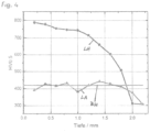
- the first full rotation for laser hardening is carried out with a laser modulation suitable for producing an edge hardness > 600 HV, followed by a second full rotation plus overlap zone for laser annealing with a laser modulation suitable for producing an edge hardness between 380 and 430 HV (see diagram according to Fig.4 ).
- a further embodiment of the invention provides that the laser modulation is suitably controlled for laser tempering to produce a maximum hardening depth of between 0.5 and 2.0 mm (see diagram according to Fig.4 ).
- a mechanical pretreatment of the surface to be processed is advantageously provided, such that an oxide layer present on the wheel rim is mechanically removed before the first rotation of the wheel disk for laser hardening and/or after each further rotation of the wheel disk for laser tempering. Otherwise, there is a risk of local temperature peaks forming, which can lead to an automatic reduction in the laser power and to soft spots (during hardening) or hard spots (during tempering).
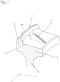
- Figure 1 shows a partial cross-section of a wheel disc 1 of a railway wheel through its axis of rotation.
- the partial section runs through the wheel rim 2 of the wheel disc 1.
- the web 3 of the wheel disc 1 running to the hub is shown in a shortened form in the area where it transitions to the wheel rim 2.
- the running surface 4 of the wheel disc 1 runs along the outer circumference of the wheel rim 2 and transitions in the radial direction via a curve 11 to the lateral guide surface of the wheel flange 5.
- the axis of rotation 6 of the wheel disc 1 of the railway wheel or the corresponding wheel set is drawn at a reduced scale.
- the laser spot 7 is shown as a narrow line shape with rounded ends, running diagonally at an angle ⁇ to an axial cutting surface. This means that when the wheel disc 1 rotates, the laser spot 7 with its longitudinal axis is correspondingly diagonally at an angle ⁇ to the rotation axis 6 and maintains this alignment during rotation of the wheel disc 1.
- the process of laser hardening railway treads on the wheel disc side can vary.
- the tempering temperature on the surface to be machined is approximately 1150 degrees Celsius, the tempering temperature is significantly lower at approximately 530 degrees Celsius.
- the laser power values for the start of the process also differ, namely for the hardening process at around 6 kW and for the tempering process at around 5 kW. Appropriate control interventions therefore result in very different values during these process sequences.
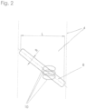
- an overlap zone 8 with an adapted, e.g. lower surface hardness can be used at the beginning and end of each full revolution of the treated wheel disc 1, which enables smooth rolling in the track-rail contact.
- the reason for this is the extensive avoidance of micro-vibrations in the laser-treated surface. Such micro-vibrations otherwise generate increasing out-of-roundness as a result of vertical dynamics within the track-rail contact.
- an overlap zone 8 corresponds approximately to a scale of 1:1 with a running surface width of 4 of approximately 60 mm.
- Such an overlap zone 8 with the width B and the length L is provided before the start of the laser track and after its end.
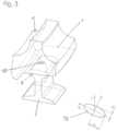
- the drawing shows the elliptical contour 10 of the Hertzian wheel-rail contact in three phases for fine-step bridging in the area of the overlap zones of the laser track, whereby the harmful vibrations that occur more frequently with the known laser spots running transversely to the track are largely avoided.
- FIG 3 shows a schematic representation of the partial circumference of a running surface 4 of a wheel disc 1 on a rail section 9 of a railway track.
- the Hertzian contact surface 10 drawn on the track corresponds to the wheel-rail contact, ie at the contact point the axes ( ⁇ , ⁇ , ⁇ ) of the contact systems of wheel and rail coincide to form the Figure 3 separately shown elliptical Hertzian contact surface 10 with the semi-axes a and b, whereby the shorter semi-axis b is aligned in the direction of travel.
- the results obtained from preliminary tests relating to the method according to the application are treated optionally by the process of pure laser hardening in a first wheel rotation or laser hardening in a first wheel rotation and subsequent laser annealing in a further wheel rotation.
- the modulation of the laser beam in terms of its power and/or its scanning speed and/or its laser spot size and/or its scanning pattern and/or the laser process time is essential.
- the running surfaces of wheel disks on railway locomotives and wagons are subject to varying degrees of wear depending on the surface hardness of the wheel disk and rail as well as the prevailing environmental conditions.
- the effect of sand as an abrasive medium at high temperatures poses an extreme challenge in terms of material wear, so that the running times between two maintenance cycles of the wheel disks on railway wheel sets are correspondingly short and lead to high operating costs.
- Test series with one or two-stage laser heat treatment were carried out with the aim of achieving an edge hardness, ie a maximum hardness in a hardening depth between 0.5 and 2.0 mm, whereby a hardening path width of approx. 60 mm was specified.
- a narrow line-shaped laser spot was chosen, for example in the form of a slim strip profile with a length-to-width ratio of between 50 and 30, preferably of about 40.
- a laser heat treatment was carried out in two process phases, comprising a first wheel rotation after the laser hardening process and/or a subsequent further wheel rotation after the laser annealing process.
- An oxide layer from the first laser process was mechanically removed to ensure stable process control during laser annealing.
- an oblique alignment of the laser spot with respect to the rotation axis was used in both process phases and an overlap zone with reduced laser power was used at the beginning and end of each full rotation in both laser processes.
- the preliminary tests were carried out with a 6 kW high-power diode laser with an optical fiber diameter of 1500 ⁇ m, using standard focusing optics with a focus diameter of 15 mm.
- a suitable scanner optics - known under the brand LASSY - was used to set a uniform temperature field and to control the laser focus width.
- the starting curve LA describes the achievement of the target ZH.
- the two-stage superficial heat input creates a pronounced temperature gradient in depth.
- a short laser process time of only nine seconds per revolution was used - without any pre- and post-processing time within the overlap zones.
- tempering parameters As far as the tempering parameters are concerned, it has been shown that a very precise coordination with regard to the optimal tempering temperature and the exposure time is required in order to achieve the uniform hardness-depth curve shown in the tempering curve LA. In particular, it has been shown that even small temperature deviations of 10 to 20 degrees Kelvin lead to clearly measurable effects, which can lead to deviations from a uniform distribution within the hardening zone, i.e. precise beam shaping must be observed within the framework of the laser spot modulation.
Landscapes
- Engineering & Computer Science (AREA)
- Chemical & Material Sciences (AREA)
- Physics & Mathematics (AREA)
- Mechanical Engineering (AREA)
- Optics & Photonics (AREA)
- Crystallography & Structural Chemistry (AREA)
- Materials Engineering (AREA)
- Metallurgy (AREA)
- Organic Chemistry (AREA)
- Thermal Sciences (AREA)
- Plasma & Fusion (AREA)
- Heat Treatment Of Articles (AREA)
- Forging (AREA)
Claims (8)
- Procédé de durcissement par laser d'une surface sensiblement cylindrique d'une pièce, en particulier de la jante (2) du disque de roue (1) d'une roue ferroviaire guidée sur rail, avec une largeur partielle de sa surface de roulement (4) exposée à l'usure et/ou la face tournée vers la surface de roulement (4) de son boudin de roue (5), comprenant les étapes de procédé suivantes :- projection d'un point laser (7) sur la surface à traiter du disque de roue (1) au moyen d'une source de laser,- génération d'un mouvement relatif entre la surface et la source de laser par rotation du disque de roue (1) autour de son axe de rotation,- pendant le mouvement de rotation, balayage du rayon laser au niveau de la surface à traiter,- modulation du rayon laser d'après différents critères, comme concernant sa puissance et/ou sa vitesse de balayage et/ou sa taille de point laser et/ou son motif de balayage,- le point laser (7) décrivant un motif de balayage à la manière d'une forme de ligne étroite transversalement à la surface à traiter en fonction de la rotation du disque de roue (1) et s'étendant sur toute sa largeur, la forme de ligne du motif de balayage s'étendant par son axe longitudinal obliquement par rapport à l'axe de rotation (6) du disque de roue (1) etla source de laser, après au moins une première rotation complète du disque de roue (1), étant utilisée, dans une zone de chevauchement (8) jouxtant le début et/ou la fin de la surface à traiter, avec une puissance réduite.
- Procédé selon la revendication 1, caractérisé en ce que l'axe longitudinal de la forme de ligne constituant le point laser (7) par rapport à un plan perpendiculaire à l'axe de rotation (6) du disque de roue (1) forme un angle α de 30 à 60 degrés, de sorte que le point laser (7) se termine en conséquence obliquement aux bords opposés de la surface à traiter.
- Procédé selon la revendication 2, caractérisé en ce que le motif de balayage du point laser (7) se termine respectivement au bord par un arrondi.
- Procédé selon la revendication 1, caractérisé en ce que le point laser (7) est modulé dans la zone de chevauchement (8) par une puissance augmentant au début d'une rotation, par une rotation décroissante à sa fin.
- Procédé selon la revendication 1, caractérisé en ce qu'au moins deux rotations complètes du disque de roue (1), une première pour le durcissement au laser, la seconde pour trempe au laser, sont effectuées.
- Procédé selon la revendication 5, caractérisé en ce que la première rotation complète pour le durcissement ou laser a lieu avec une modulation de laser appropriée pour créer une dureté de bord > 600 HV, laquelle rotation est suivie, pour trempe au laser, par une seconde rotation complète avec une modulation de laser appropriée pour créer une dureté de bord de 380 à 430 HV.
- Procédé selon la revendication 6, caractérisé en ce que, pour trempe au laser, la modulation de laser est contrôlée de manière appropriée pour créer une profondeur de dureté maximale de 0,5 à 2,0 mm.
- Procédé selon la revendication 5, caractérisé en ce que, avant la première et/ou après chaque autre rotation du disque de roue (1), une couche oxydée présente sur la jante (2) ou formée après un traitement au laser préalable est éliminée mécaniquement.
Priority Applications (2)
| Application Number | Priority Date | Filing Date | Title |
|---|---|---|---|
| HRP20241406TT HRP20241406T1 (hr) | 2020-10-23 | 2021-07-16 | Postupak laserskog kaljenja u suštini cilindrične površine izradnog predmeta |
| RS20241245A RS66143B1 (sr) | 2020-10-23 | 2021-07-16 | Postupak za lasersko očvršćavanje u suštini cilindrične površine radnog elementa |
Applications Claiming Priority (2)
| Application Number | Priority Date | Filing Date | Title |
|---|---|---|---|
| DE102020127991.4A DE102020127991A1 (de) | 2020-10-23 | 2020-10-23 | Verfahren des Laserhärtens einer im wesentlichen zylindrischen Oberfläche eines Werkstücks |
| PCT/EP2021/070010 WO2022083907A1 (fr) | 2020-10-23 | 2021-07-16 | Procédé de durcissement par laser d'une surface cylindrique d'une pièce |
Publications (3)
| Publication Number | Publication Date |
|---|---|
| EP4007822A1 EP4007822A1 (fr) | 2022-06-08 |
| EP4007822B1 true EP4007822B1 (fr) | 2024-09-04 |
| EP4007822C0 EP4007822C0 (fr) | 2024-09-04 |
Family
ID=77265056
Family Applications (1)
| Application Number | Title | Priority Date | Filing Date |
|---|---|---|---|
| EP21751994.1A Active EP4007822B1 (fr) | 2020-10-23 | 2021-07-16 | Procédé de durcissement par laser d'une surface cylindrique d'une pièce |
Country Status (14)
| Country | Link |
|---|---|
| US (1) | US20230257840A1 (fr) |
| EP (1) | EP4007822B1 (fr) |
| JP (1) | JP2023546745A (fr) |
| CN (1) | CN116648325A (fr) |
| AU (1) | AU2021365321B2 (fr) |
| CA (1) | CA3199471A1 (fr) |
| DE (1) | DE102020127991A1 (fr) |
| ES (1) | ES2991594T3 (fr) |
| HR (1) | HRP20241406T1 (fr) |
| HU (1) | HUE069248T2 (fr) |
| MX (1) | MX2023004674A (fr) |
| PL (1) | PL4007822T3 (fr) |
| RS (1) | RS66143B1 (fr) |
| WO (1) | WO2022083907A1 (fr) |
Families Citing this family (2)
| Publication number | Priority date | Publication date | Assignee | Title |
|---|---|---|---|---|
| AT527443A1 (de) | 2023-07-31 | 2025-02-15 | Siemens Mobility Austria Gmbh | Unterflurbearbeitung für Fahrwerke |
| AT527420B1 (de) | 2024-02-29 | 2025-02-15 | Siemens Mobility Austria Gmbh | Verfahren und Vorrichtung zur Bearbeitung eines Rads für ein Schienenfahrzeug |
Citations (1)
| Publication number | Priority date | Publication date | Assignee | Title |
|---|---|---|---|---|
| DD267740A1 (de) * | 1987-12-10 | 1989-05-10 | Deutsche Reichsbahn | Verfahren zum verschleissfestmachen von metallraedern |
Family Cites Families (11)
| Publication number | Priority date | Publication date | Assignee | Title |
|---|---|---|---|---|
| US4304978A (en) * | 1978-10-05 | 1981-12-08 | Coherent, Inc. | Heat treating using a laser |
| JPS5723023A (en) * | 1980-07-16 | 1982-02-06 | Toshiba Corp | Flange quenching device for wheel |
| SE469476B (sv) | 1983-02-09 | 1993-07-12 | Asea Ab | Laserhaerdat jaernvaegshjul |
| SE9303245L (sv) * | 1993-10-05 | 1995-04-06 | Johan Lennart Olofsson | Förfarande för att förbättra bestämda egenskaper på järnvägshjul |
| NL1007759C2 (nl) | 1997-12-10 | 1999-06-11 | Univ Twente | Lichaam met een gebogen metalen loopvlak en werkwijze voor het verminderen van geluidemissie. |
| DE10218141A1 (de) | 2002-04-29 | 2003-11-13 | Stiefelmayer Gmbh & Co Kg C | Verfahren zur Laser-Wärmebehandlung von Werkstücken |
| CN101929114B (zh) * | 2010-08-26 | 2012-02-08 | 中国科学院长春光学精密机械与物理研究所 | 基于火车运行对钢轨硬化的光学装置的应用方法 |
| CN102953056B (zh) * | 2011-08-18 | 2016-06-15 | 西南交通大学 | 列车车轮组合激光强化方法 |
| MX368291B (es) | 2012-09-06 | 2019-09-26 | Etxetar Sa | Procedimiento y sistema para el endurecimiento por laser de una superficie de una pieza de trabajo. |
| KR101727603B1 (ko) * | 2015-06-10 | 2017-04-19 | 한국철도기술연구원 | 철도차량의 마찰성능을 향상시키기 위한 시스템 |
| US20190218634A1 (en) * | 2018-01-15 | 2019-07-18 | Ford Global Technologies, Llc | Laser heat-treated shaft and method of making the same |
-
2020
- 2020-10-23 DE DE102020127991.4A patent/DE102020127991A1/de active Pending
-
2021
- 2021-07-16 HU HUE21751994A patent/HUE069248T2/hu unknown
- 2021-07-16 CA CA3199471A patent/CA3199471A1/fr active Pending
- 2021-07-16 CN CN202180086560.1A patent/CN116648325A/zh active Pending
- 2021-07-16 WO PCT/EP2021/070010 patent/WO2022083907A1/fr not_active Ceased
- 2021-07-16 HR HRP20241406TT patent/HRP20241406T1/hr unknown
- 2021-07-16 MX MX2023004674A patent/MX2023004674A/es unknown
- 2021-07-16 AU AU2021365321A patent/AU2021365321B2/en active Active
- 2021-07-16 PL PL21751994.1T patent/PL4007822T3/pl unknown
- 2021-07-16 RS RS20241245A patent/RS66143B1/sr unknown
- 2021-07-16 ES ES21751994T patent/ES2991594T3/es active Active
- 2021-07-16 JP JP2023548998A patent/JP2023546745A/ja active Pending
- 2021-07-16 EP EP21751994.1A patent/EP4007822B1/fr active Active
-
2023
- 2023-04-21 US US18/137,816 patent/US20230257840A1/en active Pending
Patent Citations (1)
| Publication number | Priority date | Publication date | Assignee | Title |
|---|---|---|---|---|
| DD267740A1 (de) * | 1987-12-10 | 1989-05-10 | Deutsche Reichsbahn | Verfahren zum verschleissfestmachen von metallraedern |
Also Published As
| Publication number | Publication date |
|---|---|
| PL4007822T3 (pl) | 2025-01-20 |
| JP2023546745A (ja) | 2023-11-07 |
| ES2991594T3 (es) | 2024-12-04 |
| HUE069248T2 (hu) | 2025-02-28 |
| HRP20241406T1 (hr) | 2024-12-20 |
| CA3199471A1 (fr) | 2022-04-28 |
| AU2021365321B2 (en) | 2025-09-18 |
| MX2023004674A (es) | 2023-08-11 |
| EP4007822C0 (fr) | 2024-09-04 |
| AU2021365321A9 (en) | 2024-02-08 |
| DE102020127991A1 (de) | 2022-04-28 |
| AU2021365321A1 (en) | 2023-06-08 |
| EP4007822A1 (fr) | 2022-06-08 |
| RS66143B1 (sr) | 2024-12-31 |
| CN116648325A (zh) | 2023-08-25 |
| WO2022083907A1 (fr) | 2022-04-28 |
| US20230257840A1 (en) | 2023-08-17 |
Similar Documents
| Publication | Publication Date | Title |
|---|---|---|
| EP0144817B1 (fr) | Procédé pour la fabrication de surfaces de contact de cylindres de moteurs à combustion interne résistantes à l'usure | |
| EP4007822B1 (fr) | Procédé de durcissement par laser d'une surface cylindrique d'une pièce | |
| EP2371656A1 (fr) | Véhicule sur rails doté d'une géométrie d'essieu variable | |
| DE3509582C1 (de) | Metallrad, insbesondere Eisenbahnrad | |
| DE69706211T2 (de) | Verfahren zum Durchführen einer Bainittransformation mit Temperaturanstieg | |
| AT518517B1 (de) | Verfahren zum Bearbeiten einer Oberfläche eines metallischen Bauteils und metallisches Bauteil | |
| DE102007039385B3 (de) | Verfahren zur lokalen Festigung von Eisenbahnradsätzen | |
| EP3406392B1 (fr) | Procédé de réduction du frottement de surfaces glissantes et/ou roulantes les unes par rapport aux autres | |
| EP0925855A2 (fr) | Dispositif pour le refroidissement contrÔlé de profilés laminés à chaud, en particulier de poutres, directement à partir de la température de laminage | |
| AT502101B1 (de) | Verfahren zur bearbeitung von laufflächen von wintersportgeräten sowie wintersportgerät und vorrichtung zur herstellung von belägen | |
| EP3511467B1 (fr) | Procédé de reconstruction d'un profilé de rail | |
| AT527420B1 (de) | Verfahren und Vorrichtung zur Bearbeitung eines Rads für ein Schienenfahrzeug | |
| DE102008041562A1 (de) | Verfahren zum Laserstrahlpolieren | |
| DE4231957C1 (fr) | ||
| DE102014203088A1 (de) | Vorrichtung zum Glätten einer Verzahnung und Verfahren zu Herstellung | |
| EP2601322B1 (fr) | Procédé de traitement thermique de la jante de roues de véhicules sur rails | |
| DE4421238A1 (de) | Verfahren zur Herstellung beanspruchungsgerecht verschleißfester, rotierend bewegter Draht-, Seil- und/oder Drahtseillaufflächen, insbesondere Oberflächen von Drahtziehtrommeln aus Drahtziehmaschinen oder ähnlichen Transportrollen oder Trommeln | |
| EP4096865B1 (fr) | Procédé de reprofilage d'au moins un rail | |
| DE102024127746A1 (de) | Verfahren zur Herstellung einer Kurventrommel für eine Transporteinrichtung | |
| DD267740A1 (de) | Verfahren zum verschleissfestmachen von metallraedern | |
| EP0115046A2 (fr) | Roue pour véhicule ferroviaire | |
| WO2025026704A1 (fr) | Usinage sous châssis pour trains roulants | |
| CH712700A2 (de) | Verfahren zur Herstellung von Führungsschienen für ein Linearwälzlager. | |
| DE662453C (de) | Gluehverfahren zur Vorbereitung hartgebremster Schienenstahlraeder zum Abdrehen der abgeplatteten Radlaufflaeche | |
| EP4619554A1 (fr) | Traitement thermique d'un composant métallique |
Legal Events
| Date | Code | Title | Description |
|---|---|---|---|
| REG | Reference to a national code |
Ref country code: HR Ref legal event code: TUEP Ref document number: P20241406T Country of ref document: HR |
|
| STAA | Information on the status of an ep patent application or granted ep patent |
Free format text: STATUS: UNKNOWN |
|
| STAA | Information on the status of an ep patent application or granted ep patent |
Free format text: STATUS: THE INTERNATIONAL PUBLICATION HAS BEEN MADE |
|
| PUAI | Public reference made under article 153(3) epc to a published international application that has entered the european phase |
Free format text: ORIGINAL CODE: 0009012 |
|
| STAA | Information on the status of an ep patent application or granted ep patent |
Free format text: STATUS: REQUEST FOR EXAMINATION WAS MADE |
|
| 17P | Request for examination filed |
Effective date: 20211020 |
|
| AK | Designated contracting states |
Kind code of ref document: A1 Designated state(s): AL AT BE BG CH CY CZ DE DK EE ES FI FR GB GR HR HU IE IS IT LI LT LU LV MC MK MT NL NO PL PT RO RS SE SI SK SM TR |
|
| STAA | Information on the status of an ep patent application or granted ep patent |
Free format text: STATUS: EXAMINATION IS IN PROGRESS |
|
| 17Q | First examination report despatched |
Effective date: 20230523 |
|
| DAV | Request for validation of the european patent (deleted) | ||
| DAX | Request for extension of the european patent (deleted) | ||
| RIC1 | Information provided on ipc code assigned before grant |
Ipc: C21D 9/34 20060101ALI20240306BHEP Ipc: C21D 1/09 20060101AFI20240306BHEP |
|
| GRAP | Despatch of communication of intention to grant a patent |
Free format text: ORIGINAL CODE: EPIDOSNIGR1 |
|
| STAA | Information on the status of an ep patent application or granted ep patent |
Free format text: STATUS: GRANT OF PATENT IS INTENDED |
|
| INTG | Intention to grant announced |
Effective date: 20240418 |
|
| GRAJ | Information related to disapproval of communication of intention to grant by the applicant or resumption of examination proceedings by the epo deleted |
Free format text: ORIGINAL CODE: EPIDOSDIGR1 |
|
| STAA | Information on the status of an ep patent application or granted ep patent |
Free format text: STATUS: EXAMINATION IS IN PROGRESS |
|
| GRAP | Despatch of communication of intention to grant a patent |
Free format text: ORIGINAL CODE: EPIDOSNIGR1 |
|
| STAA | Information on the status of an ep patent application or granted ep patent |
Free format text: STATUS: GRANT OF PATENT IS INTENDED |
|
| INTC | Intention to grant announced (deleted) | ||
| INTG | Intention to grant announced |
Effective date: 20240617 |
|
| GRAS | Grant fee paid |
Free format text: ORIGINAL CODE: EPIDOSNIGR3 |
|
| GRAA | (expected) grant |
Free format text: ORIGINAL CODE: 0009210 |
|
| STAA | Information on the status of an ep patent application or granted ep patent |
Free format text: STATUS: THE PATENT HAS BEEN GRANTED |
|
| AK | Designated contracting states |
Kind code of ref document: B1 Designated state(s): AL AT BE BG CH CY CZ DE DK EE ES FI FR GB GR HR HU IE IS IT LI LT LU LV MC MK MT NL NO PL PT RO RS SE SI SK SM TR |
|
| REG | Reference to a national code |
Ref country code: GB Ref legal event code: FG4D Free format text: NOT ENGLISH |
|
| REG | Reference to a national code |
Ref country code: CH Ref legal event code: EP |
|
| REG | Reference to a national code |
Ref country code: IE Ref legal event code: FG4D Free format text: LANGUAGE OF EP DOCUMENT: GERMAN |
|
| REG | Reference to a national code |
Ref country code: DE Ref legal event code: R096 Ref document number: 502021005068 Country of ref document: DE |
|
| U01 | Request for unitary effect filed |
Effective date: 20240927 |
|
| U07 | Unitary effect registered |
Designated state(s): AT BE BG DE DK EE FI FR IT LT LU LV MT NL PT RO SE SI Effective date: 20241024 |
|
| REG | Reference to a national code |
Ref country code: SK Ref legal event code: T3 Ref document number: E 45063 Country of ref document: SK Ref country code: ES Ref legal event code: FG2A Ref document number: 2991594 Country of ref document: ES Kind code of ref document: T3 Effective date: 20241204 |
|
| REG | Reference to a national code |
Ref country code: HR Ref legal event code: T1PR Ref document number: P20241406 Country of ref document: HR |
|
| PG25 | Lapsed in a contracting state [announced via postgrant information from national office to epo] |
Ref country code: GR Free format text: LAPSE BECAUSE OF FAILURE TO SUBMIT A TRANSLATION OF THE DESCRIPTION OR TO PAY THE FEE WITHIN THE PRESCRIBED TIME-LIMIT Effective date: 20241205 |
|
| PG25 | Lapsed in a contracting state [announced via postgrant information from national office to epo] |
Ref country code: GR Free format text: LAPSE BECAUSE OF FAILURE TO SUBMIT A TRANSLATION OF THE DESCRIPTION OR TO PAY THE FEE WITHIN THE PRESCRIBED TIME-LIMIT Effective date: 20241205 |
|
| REG | Reference to a national code |
Ref country code: HU Ref legal event code: AG4A Ref document number: E069248 Country of ref document: HU |
|
| PG25 | Lapsed in a contracting state [announced via postgrant information from national office to epo] |
Ref country code: IS Free format text: LAPSE BECAUSE OF FAILURE TO SUBMIT A TRANSLATION OF THE DESCRIPTION OR TO PAY THE FEE WITHIN THE PRESCRIBED TIME-LIMIT Effective date: 20250104 |
|
| PG25 | Lapsed in a contracting state [announced via postgrant information from national office to epo] |
Ref country code: SM Free format text: LAPSE BECAUSE OF FAILURE TO SUBMIT A TRANSLATION OF THE DESCRIPTION OR TO PAY THE FEE WITHIN THE PRESCRIBED TIME-LIMIT Effective date: 20240904 |
|
| PLBE | No opposition filed within time limit |
Free format text: ORIGINAL CODE: 0009261 |
|
| STAA | Information on the status of an ep patent application or granted ep patent |
Free format text: STATUS: NO OPPOSITION FILED WITHIN TIME LIMIT |
|
| 26N | No opposition filed |
Effective date: 20250605 |
|
| REG | Reference to a national code |
Ref country code: HR Ref legal event code: ODRP Ref document number: P20241406 Country of ref document: HR Payment date: 20250710 Year of fee payment: 5 |
|
| U20 | Renewal fee for the european patent with unitary effect paid |
Year of fee payment: 5 Effective date: 20250731 |
|
| PGFP | Annual fee paid to national office [announced via postgrant information from national office to epo] |
Ref country code: HU Payment date: 20250711 Year of fee payment: 5 |
|
| PGFP | Annual fee paid to national office [announced via postgrant information from national office to epo] |
Ref country code: ES Payment date: 20250819 Year of fee payment: 5 |
|
| PGFP | Annual fee paid to national office [announced via postgrant information from national office to epo] |
Ref country code: NO Payment date: 20250725 Year of fee payment: 5 |
|
| PGFP | Annual fee paid to national office [announced via postgrant information from national office to epo] |
Ref country code: TR Payment date: 20250710 Year of fee payment: 5 Ref country code: PL Payment date: 20250704 Year of fee payment: 5 |
|
| PGFP | Annual fee paid to national office [announced via postgrant information from national office to epo] |
Ref country code: GB Payment date: 20250724 Year of fee payment: 5 |
|
| PGFP | Annual fee paid to national office [announced via postgrant information from national office to epo] |
Ref country code: HR Payment date: 20250710 Year of fee payment: 5 |
|
| PGFP | Annual fee paid to national office [announced via postgrant information from national office to epo] |
Ref country code: CH Payment date: 20250801 Year of fee payment: 5 |
|
| PGFP | Annual fee paid to national office [announced via postgrant information from national office to epo] |
Ref country code: IE Payment date: 20250724 Year of fee payment: 5 Ref country code: RS Payment date: 20250708 Year of fee payment: 5 Ref country code: CZ Payment date: 20250703 Year of fee payment: 5 |
|
| PGFP | Annual fee paid to national office [announced via postgrant information from national office to epo] |
Ref country code: SK Payment date: 20250710 Year of fee payment: 5 |