EP4007841B1 - Zahnrad mit verbessertem profil - Google Patents
Zahnrad mit verbessertem profil Download PDFInfo
- Publication number
- EP4007841B1 EP4007841B1 EP20745234.3A EP20745234A EP4007841B1 EP 4007841 B1 EP4007841 B1 EP 4007841B1 EP 20745234 A EP20745234 A EP 20745234A EP 4007841 B1 EP4007841 B1 EP 4007841B1
- Authority
- EP
- European Patent Office
- Prior art keywords
- gear wheel
- tooth
- cutting edge
- profile
- teeth
- Prior art date
- Legal status (The legal status is an assumption and is not a legal conclusion. Google has not performed a legal analysis and makes no representation as to the accuracy of the status listed.)
- Active
Links
Images





Classifications
-
- B—PERFORMING OPERATIONS; TRANSPORTING
- B23—MACHINE TOOLS; METAL-WORKING NOT OTHERWISE PROVIDED FOR
- B23F—MAKING GEARS OR TOOTHED RACKS
- B23F15/00—Methods or machines for making gear wheels of special kinds not covered by groups B23F7/00 - B23F13/00
- B23F15/08—Making intermeshing rotors, e.g. of pumps
-
- F—MECHANICAL ENGINEERING; LIGHTING; HEATING; WEAPONS; BLASTING
- F01—MACHINES OR ENGINES IN GENERAL; ENGINE PLANTS IN GENERAL; STEAM ENGINES
- F01C—ROTARY-PISTON OR OSCILLATING-PISTON MACHINES OR ENGINES
- F01C1/00—Rotary-piston machines or engines
- F01C1/08—Rotary-piston machines or engines of intermeshing engagement type, i.e. with engagement of co- operating members similar to that of toothed gearing
- F01C1/082—Details specially related to intermeshing engagement type machines or engines
- F01C1/084—Toothed wheels
-
- F—MECHANICAL ENGINEERING; LIGHTING; HEATING; WEAPONS; BLASTING
- F04—POSITIVE - DISPLACEMENT MACHINES FOR LIQUIDS; PUMPS FOR LIQUIDS OR ELASTIC FLUIDS
- F04C—ROTARY-PISTON, OR OSCILLATING-PISTON, POSITIVE-DISPLACEMENT MACHINES FOR LIQUIDS; ROTARY-PISTON, OR OSCILLATING-PISTON, POSITIVE-DISPLACEMENT PUMPS
- F04C2/00—Rotary-piston machines or pumps
- F04C2/08—Rotary-piston machines or pumps of intermeshing-engagement type, i.e. with engagement of co-operating members similar to that of toothed gearing
- F04C2/082—Details specially related to intermeshing engagement type machines or pumps
- F04C2/084—Toothed wheels
-
- F—MECHANICAL ENGINEERING; LIGHTING; HEATING; WEAPONS; BLASTING
- F04—POSITIVE - DISPLACEMENT MACHINES FOR LIQUIDS; PUMPS FOR LIQUIDS OR ELASTIC FLUIDS
- F04C—ROTARY-PISTON, OR OSCILLATING-PISTON, POSITIVE-DISPLACEMENT MACHINES FOR LIQUIDS; ROTARY-PISTON, OR OSCILLATING-PISTON, POSITIVE-DISPLACEMENT PUMPS
- F04C2/00—Rotary-piston machines or pumps
- F04C2/08—Rotary-piston machines or pumps of intermeshing-engagement type, i.e. with engagement of co-operating members similar to that of toothed gearing
- F04C2/12—Rotary-piston machines or pumps of intermeshing-engagement type, i.e. with engagement of co-operating members similar to that of toothed gearing of other than internal-axis type
- F04C2/14—Rotary-piston machines or pumps of intermeshing-engagement type, i.e. with engagement of co-operating members similar to that of toothed gearing of other than internal-axis type with toothed rotary pistons
- F04C2/16—Rotary-piston machines or pumps of intermeshing-engagement type, i.e. with engagement of co-operating members similar to that of toothed gearing of other than internal-axis type with toothed rotary pistons with helical teeth, e.g. chevron-shaped, screw type
-
- Y—GENERAL TAGGING OF NEW TECHNOLOGICAL DEVELOPMENTS; GENERAL TAGGING OF CROSS-SECTIONAL TECHNOLOGIES SPANNING OVER SEVERAL SECTIONS OF THE IPC; TECHNICAL SUBJECTS COVERED BY FORMER USPC CROSS-REFERENCE ART COLLECTIONS [XRACs] AND DIGESTS
- Y10—TECHNICAL SUBJECTS COVERED BY FORMER USPC
- Y10T—TECHNICAL SUBJECTS COVERED BY FORMER US CLASSIFICATION
- Y10T29/00—Metal working
- Y10T29/49—Method of mechanical manufacture
- Y10T29/49462—Gear making
- Y10T29/49467—Gear shaping
Definitions
- the present invention refers to a gear wheel for a hydraulic apparatus, for example for a geared rotary positive displacement pump, and the following description is made with reference to this application field with the only purpose of simplifying the exposition thereof.
- geared rotary positive displacement pumps normally comprise two gear wheels (or gears) of which one, called driving wheel, is connected to a driving shaft and causes the rotation of the other wheel, called the driven wheel.
- Each gear wheel comprises a plurality of teeth, straight or helical, which are configured to mesh with each other according to successive meshing configurations during the rotation of the wheels.
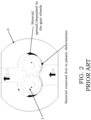
- a geared rotary positive displacement pump is equipped with a pair of gear wheels 1 whose teeth 2 have a profile characterized by a round or arched shape at the top.
- a gear wheel of this type allows a continuous contact between the profiles of the two meshing wheels, in whatever angular position they are, so that there is no fluid encapsulation between the crest and the bottom of two meshing teeth. This happens for example when the shape of the tooth at the top thereof is defined by a function describing an arc of a circle or ellipse, wherein the center thereof or the foci thereof are located inside the tooth itself between the outer diameter and the inner diameter of the gear wheel 1.
- the biggest critical issue for this type of pumps occurs during the running-in phase, where the gear wheels 1, under the load due to the pressure created on the delivery port, create their own seat in the body 3 of the pump.
- the gear wheels 1 contact the internal walls of the body 3 of the pump in the area close to the low pressure port and, since the wheels themselves are made of a material having a hardness greater than the material of the body 3, the geometry of the latter is altered.
- the seat created by the gear wheel once back to the starting temperature, has a deformed geometry such as to interfere with the rotation of the wheel itself.
- the extent of the deformation is also difficult to predict.
- Patent application DE 10 2012 209 775 A1 discloses a pump whose gear wheels comprise a tooth equipped with a cutting edge for removing material from the pump casing, in particular when the latter is made of grey cast iron.
- the cutting edge is basically a pronounced protrusion of the tooth and defines an acute cutting angle.
- the technical problem of the present invention is to provide a gear wheel, and a related hydraulic apparatus, having structural and functional features such as to allow overcoming the limitations and drawbacks still affecting the known solutions, in particular which does not cause a plastic deformation of the pump body with consequent spreading of material on the surface of the holes housing the gear wheels during the running-in phase.
- the solution idea underlying the present invention is to provide a gear wheel whose teeth comprise a cutting element, which is arranged on the top thereof and is capable of removing material from the pump body by removing chips during the running-in phase, so as to limit or even avoid the plastic deformation of the pump body which occurs in the known solutions.
- the removed material is then expelled by the fluid pumped by the delivery port, with limited or even no spreading of material on the walls of the housing holes.
- the present disclosure also refers to a not claimed method for manufacturing a gear wheel of the type rotatable about an axis of rotation and comprising a plurality of teeth adapted to mesh with respective teeth of another gear wheel during a rotational motion around the axis of rotation, comprising the steps of:
- the method can comprise a step of performing a shape grinding of the tooth profile, by using a single shaped grinding wheel or a screw grinding wheel.
- the method can comprise a step of grinding the diameter of the gear wheel by means of a round grinding machine.
- a gear wheel according to the present invention is globally and schematically indicated with 10.
- the gear wheel 10 of the present invention is used in hydraulic apparatuses such as volumetric gear pumps (geared rotary positive displacement pumps) or also hydraulic gear motors.
- the gear wheel 10 is used in a hydraulic apparatus comprising a pair of meshing gear wheels, the wheels being mounted so as to be mutually rotatable in a casing or housing body between an inlet side and an outlet side of a fluid having, in use, a flow which is substantially transverse with respect to the axes of rotation of the gear wheels.
- these meshing gear wheels In their reciprocal rotation, these meshing gear wheels have progressive meshing configurations.
- the present invention will be illustrated below according to a preferred example in which the gear wheel 10 is used in a gear pump, even if the disclosed teachings will also be applicable to other hydraulic systems, such as a motor.
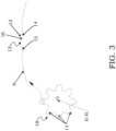
- the gear wheel 10 of the present invention also called rotor in this field, comprises a main body which is processed so as to have a plurality of teeth 11, which are adapted to mesh with respective and conjugate teeth of another gear wheel during rotation.
- the gear wheel 10 is arranged so as to be rotatable about an axis of rotation, indicated herein as the axis H-H, which is perpendicular to the plane of the figure and configured as an axis passing through the center O of the gear wheel 10, i.e. from the center of the primitive circle.
- Each tooth 11 has a cross-sectional profile P defined by a determined function on a plane orthogonal to this axis of rotation H-H.
- the function that defines the profile P of the teeth 11 may describe an arc of a circle at the top of the tooth, said circle being centered in the center O and having a diameter substantially equal to or greater than that of the holes housing the wheel in the pump body, except for processing tolerances.
- the present invention is inspired by a profile of this type, which has a rounded shape at the top of the tooth.
- At least one tooth 11 of the gear wheel 10 is shaped so as to comprise a cutting edge 12 at at least a portion 13 thereof, for example at the top of the tooth.
- the cutting edge 12 of the tooth 11 is an active end thereof adapted to remove material in the form of chips from a body which is in contact with the cutting edge, for example from the surface of the housing holes of the pump casing, in particular during the rotation of the gear wheel 10 in the running-in phase of the apparatus in which it is housed, as will be illustrated in greater detail below.
- the function that defines its profile P is therefore suitably modified, for example by introducing a discontinuity or in general an irregularity.
- the cutting edge 12 is obtained as the edge of a longitudinal groove 14 which preferably affects the entire length or depth of the tooth 11 or of the wheel 10.
- the teeth 11 of the gear wheel 10 are provided with at least one cutting surface for removing material during the rotation of the wheel.
- This configuration entails considerable advantages, especially during the running-in phase of the pump, as will be described in detail below.
- the portion 13 of the tooth 11 in which the cutting edge 12 is formed is a top portion of said tooth 11, where the term “top” means herein the portion of the tooth furthest from the center O of the primitive circle of the gear wheel 10.
- the cutting edge 12 extends over the entire length or depth of the tooth 11, where the term "length of the tooth” means herein the dimension of the tooth 11 along a direction parallel to the axis of rotation H-H.
- the cutting edge 12 is obtained by removing material from the tooth 11, in particular at the portion 13 of the tooth 11, for example at at least one side of said portion 13, forming the aforementioned groove 14 extended longitudinally along the development (depth) of the tooth 11.
- a second groove 15 analogous to the groove 14 is formed parallel to the previous groove 14 (for instance at another side of the portion 13), defining between said grooves a projection 16 corresponding, in this embodiment, to the portion 13.
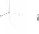
- the reference P' indicates the profile of the tooth of the known solutions, having a typical round or rounded shape without interruption, while the profile P of the tooth 11 of the present invention has, in its section, the projection 16 obtained by the aforementioned material removal by means of the two parallel grooves 14 and 15, with the formation of the cutting edge 12 for example on a longitudinal edge of the projection 16.
- the shape of the cutting edge 12 is obtained by shape grinding to obtain the groove 14 (and consequently the cutting edge 12) by using for example a single shaped grinding wheel, or it is obtained by using a screw grinding wheel.
- the grinding of the outer diameter of the gear wheel 10 is achieved by means of round grinding machines, so that the function which defines the profile P of the teeth 11 describes, at the top of each tooth, an arc of a circle centered on the axis of rotation H-H of the gear wheel 10 and having a diameter equal to (or greater than) a diameter of the housing hole, as indicated above.
- the modification of the known profile due to the material removal can lead to a decrease in the height of the tooth (at the foot of the cutting edge 12) equal to about 0.1 mm, this value shrinking more and more as we move away from the cutting edge 12, resulting in a protrusion of the projection 16 with respect to the rest of the remaining profile of about 0.03 mm.
- each tooth 11 of the gear wheel 10 comprises the cutting edge 12, even if other solutions are within the scope of the present invention; it is in fact possible to provide for a configuration in which the cutting edge 12 is present only on some teeth of the gear wheel, for example a configuration in which a tooth comprising the cutting edge alternates with a tooth that does not include any cutting edge.
- At least one tooth 11 comprises a plurality of cutting edges 12 spaced from each other along the profile P, for example equally spaced, such as for example the teeth of a saw.
- the tooth 11 comprises a plurality of portions 13 which have the cutting edge 12, said portions being spatially spaced from each other (for example, equally spaced) along the profile P of the tooth 11.
- the cutting edge 12 introduces a discontinuity in the function that defines the profile P of the tooth 11, for example a discontinuity of the first kind (for example in the form of a step), in which at the left of the cutting edge 12 the function that describes this profile P approaches the cutting point with a value that is different from the one it has when approaching from the right.
- a discontinuity of the first kind for example in the form of a step
- the cutting edge 12 introduces a point of non-differentiability in the function that defines the profile P of the tooth 11.
- the cutting edge 12 can introduce a corner point or a cusp.
- Figure 7 shows various alternative solutions indicated with the letters from (a) to (p) which illustrate a section of the tooth 11 at portion 13 (i.e. a top portion).
- the solution (a) substantially corresponds to the example embodiment of figures 3 to 6 discussed above, while the other solutions can be considered as alternative embodiment.
- the tooth portion 13 comprising the cutting edge 12 can be considered a projection 16 formed in the top profile, as for example in the embodiment of figures from 3 to 6 and of figure 7(a) , or in general obtained by means of at least one longitudinal groove 14, preferably extended over the entire length of the tooth.
- the projection 16 of the embodiment of figures 3 to 6 and of figure 7(a) is to be understood in a relative way with respect to the depression (dip) at the flanks of said projection; in other words, the projection 16 is a discontinuity made by means of at least one groove 14 extended over the entire length or depth of the tooth, and it does not protrude much beyond the rounded line of the effective profile P of tooth 11 (it protrudes in fact preferably by about 0.03 mm, in a range from 0.01 mm to 1 mm), and defines the cutting edge 12 in at least one edge where a change of level with respect to the center O of this tooth 11 occurs.
- the maximum height at the projection 16 is preferably substantially equal to the maximum height of the profile of the tooth of the known solutions, from which material is then removed as illustrated above, obtaining said projection 16.
- the projection 16 has a width (intended as a transverse dimension with respect to the length of the tooth) between 0.01 mm and 1 mm.
- the cutting edge 12 is made by means of at least one groove 14 which is lowered by an amount from 0.2% to 5%, preferably from 0.2% to 1.5%, still more preferably 0.8%, of the height H' of the tooth 11, the groove 14 decreasing away from the cutting edge 12 along the profile P of said tooth 11.
- the cutting edge 12 introduces, at the top of the tooth 11, a discontinuity in the function that defines the profile P of said tooth 11 made by means of such lowered groove 14.
- the term height H' means the distance between the top of the tooth and the base at the primitive circle, for example measured along a direction orthogonal to the length of the tooth.
- the groove 14 can vary from 0.01 to 0.2 cm, preferably 0.03 cm.
- the maximum values of the range indicated above are more suitable for large-sized teeth, for example having a height greater than 10 cm.
- the described configuration allows to obtain an extremely resistant cutting edge 12 which is not subject to breakage, since it protrudes very little. Furthermore, the described configuration can be easily made with no need for complicated processing, requiring only a minimal removal of material to form the aforementioned groove 14.
- the cutting edge 12 is arranged at a rim of the portion 13 (i.e. it is the edge of said portion), which therefore can have any shape, for example a square or a wedge shape.
- the tooth 11 has thus a profile P provided with a sharp portion.
- the profile P of the tooth 11 can be a symmetrical profile (such as the profile of the embodiment of figures 3 to 6 and of figure 7(a) ), or the profile P can be an antisymmetric profile.
- the teeth 11 are helical teeth
- the gear wheel 10 has a number of teeth between 5 and 21, preferably 5-11, still more preferably 8.
- a hydraulic apparatus 100 including a pair of gear wheels 10 according to the present invention is disclosed.
- the gear wheels 10 In their mutual rotation, the gear wheels 10 cause meshing between respective cooperating teeth.
- the grinding of the outer diameter of the gear wheel 10 is such that the function that defines the profile P of the teeth 11 describes, at the top of each tooth, an arc of a circle centered on the axis of rotation H-H of the gear wheel 10 and having a diameter equal to a diameter of a hole housing the wheel, except for processing tolerances.
- the starting shape of the tooth 11 at the top thereof is expressed by a function that describes an arc of a circle or ellipse, whose center or foci are located inside the tooth itself (between the outer diameter and the inner diameter of the gear wheel).
- the improved profile comprising the cutting edge allows in any case to obtain gear wheels having a "continuous contact" along almost the whole profile, that is, there is a single theoretical contact point that moves from one flank of the gear wheel to the other one with continuity, without generating areas of entrapment of fluid during meshing (i.e. not encapsulating fluid).
- the aforesaid contact does not take place only in the portion affected by the cutting edge 12.
- a small encapsulation volume is created, but the cutting edge 12 is designed and sized in such a way as to make said modification completely imperceptible.
- there are no volumetric losses due to leakage of the pumped fluid and the excellent characteristics of noiselessness of these apparatuses are maintained.
- the non-incapsulating profile is thus suitably modified by introducing the cutting edge 12 of the present invention.
- the starting profile on which the cutting edge is made is a so-called semi-encapsulating profile, wherein an area of entrapment or encapsulation of fluid is formed between the teeth of two meshing wheels, said area decreasing gradually during the rotation of the wheels, until it is substantially cancelled off when the head of a tooth of a gear wheel touches the bottom of a tooth of the other wheel.
- the apparatus 100 comprises a casing or body 110, which is provided with housing through holes 120 for housing the gear wheels 10.
- the hydraulic apparatus 100 can be a volumetric rotary gear pump or a hydraulic motor.
- the gear wheels 10 are made of a material, for example steel, having a hardness that is greater than the material of the casing 110, for example aluminium, so that the aforementioned mechanical interference between the gear wheels 10 and the casing 110 generates, in the known solutions, a wear phenomenon due to plastic deformation, in particular due to the particular shape of the rotor tooth, which is rounded at the tip.
- the cutting edge 12 is configured to remove chip material from the inner surface of the housing holes 120 of the casing 110, which is contacted by the cutting edge during the rotation of the gear wheels 10.
- the cutting edge 12 acts by removing material in the form of chips, which is then expelled together with the pumped fluid from the delivery port with limited or even absence of fill/spreading of material on the inner surface of the housing holes 120.
- the final geometry of the housing hole (which can be expected with modest tolerance dimensions) does not affect the performance of the apparatus.
- the innovation made to the profile P of the tooth 11 of the gear wheel 10 therefore allows to improve the performance and the working life of the hydraulic apparatus 100 which incorporates said gear wheel 10, by speeding up the running-in times and ensuring an improvement in the overall quality in terms of constancy, reliability and repetitiveness of the parameters characterizing it.
- the cutting edge 12 on the top of the teeth 11 in fact eliminates the problems of some known profiles which, due to the exclusively round shape, sometimes creates irreversible damage to the body of the apparatus itself at the end of the running-in phase.
- the adopted configuration allows in any case to minimize the losses due to fluid leakage, and in general the pump performance is in no way affected by the presence of the cutting edge 12.
Landscapes
- Engineering & Computer Science (AREA)
- Mechanical Engineering (AREA)
- General Engineering & Computer Science (AREA)
- Rotary Pumps (AREA)
- Gear Transmission (AREA)
- Gears, Cams (AREA)
- Endoscopes (AREA)
Claims (18)
- Zahnrad (10) für eine hydraulische Vorrichtung, das mehrere Zähne (11) aufweist und dafür ausgelegt ist, sich um eine Drehachse (H-H) zu drehen, wobei die Zähne (11) ein Schnittprofil (P) besitzen und dafür ausgelegt sind, während einer Drehbewegung um die Drehachse (H-H) mit entsprechenden Zähnen eines weiteren Zahnrades zu kämmen, wobei wenigstens ein Zahn (11) so geformt ist, dass er wenigstens eine Schneidkante (12) besitzt, die konfiguriert ist, von einem Körper, der während der Drehung des Zahnrades (10) von der Schneidkante kontaktiert wird, Material zu entfernen, dadurch gekennzeichnet, dass die Schneidkante (12) durch wenigstens eine Nut (14) definiert ist, die in Bezug auf ein anfängliches abgerundetes Profil (P') ohne Nut (14) um einen Betrag von 0,2 % bis 5 % der Höhe (H') des Zahns (11) erniedrigt ist, wobei die Nut (14) weg von der Schneidkante (12) längs des Profils (P) abfällt, wobei die Nut (14) einen Vorsprung (16) bildet, der die Schneidkante (12) enthält und der in Bezug auf das abgerundete Profil (P) des Zahns (11) um einen Betrag von 0,01 mm bis 1 mm vorsteht, und wobei der Vorsprung (16) eine Breite von 0,01 bis 1 mm besitzt, wobei die Breite als Querabmessung bezüglich der Länge des Zahns gedacht ist.
- Zahnrad (10) nach Anspruch 1, wobei sich die Schneidkante (12) an einem oberen Abschnitt des Zahns (11) befindet, wobei der obere Abschnitt der Zahnabschnitt ist, der am weitesten vom Zentrum (O) des Grundkreises des Zahnrades (10) entfernt ist.
- Zahnrad (10) nach einem der vorhergehenden Ansprüche, wobei sich die Schneidkante (12) über die gesamte Länge des Zahns (11) erstreckt, wobei die Länge des Zahns die Abmessung des Zahns (11) in einer Richtung parallel zu der Drehachse (H-H) ist.
- Zahnrad (10) nach einem der vorhergehenden Ansprüche, wobei jeder Zahn (11) eine solche Schneidkante (12) aufweist.
- Zahnrad (10) nach einem der vorhergehenden Ansprüche, wobei wenigstens ein Zahn (11) mehrere voneinander beanstandete Schneidkanten (12) aufweist.
- Zahnrad (10) nach einem der vorhergehenden Ansprüche, wobei die Schneidkante (12) so beschaffen ist, dass sie in die Funktion, die das Profil (P) des Zahns (11) definiert, eine Unstetigkeit einbringt, wobei die Schneidkante (12) an dem Punkt der Unstetigkeit angeordnet ist.
- Zahnrad (10) nach Anspruch 6, wobei die Unstetigkeit eine Unstetigkeit erster Art ist.
- Zahnrad (10) nach einem der Ansprüche 1 bis 5, wobei die Schneidkante (12) so beschaffen ist, dass sie in die Funktion, die das Profil (P) des Zahns (11) definiert, einen Punkt der Nichtdifferenzierbarkeit einbringt.
- Zahnrad (10) nach einem der vorhergehenden Ansprüche, wobei das Profil (P) des Zahns (11) ein symmetrisches Profil ist.
- Zahnrad (10) nach einem der vorhergehenden Ansprüche, wobei die Schneidkante (12) eine Kante der Nut (14) ist, die entlang einer Längsachse des Zahns (11) gebildet ist, wobei die Längsachse eine Achse parallel zu der Drehachse (H-H) ist.
- Zahnrad (10) nach Anspruch 10, wobei die Schneidkante (12) die Kante eines Abschnitts (13) mit einer quadratischen Form oder einer Keilform ist.
- Zahnrad (10) nach einem der vorhergehenden Ansprüche, wobei der Zahn (11) ein gewendelter oder doppelt gewendelter Zahn ist.
- Zahnrad (10) nach einem der vorhergehenden Ansprüche, das eine Anzahl von Zähnen (11) zwischen 5 und 21 hat.
- Zahnrad (10) nach Anspruch 1, wobei die Funktion, die das Profil (P) des Zahns (11) an seiner Oberseite beschreibt, ein Kreisbogen ist, der auf die Drehachse (H-H) des Zahnrades (10) zentriert ist und einen Durchmesser hat, der gleich oder größer als ein Durchmesser eines Lochs ist, das das Zahnrad (10) aufnimmt, wobei die Oberseite des Zahns (11) der Zahnabschnitt ist, der am weitesten vom Zentrum des Grundkreises des Zahnrades (10) entfernt ist.
- Zahnrad (10) nach Anspruch 1, wobei die Schneidkante (12) durch Entfernen von Material von dem Zahn (11) erhalten wird.
- Zahnrad (10) nach Anspruch 15, wobei die Form der Schneidkante (12) durch Formschleifen unter Verwendung eines einzeln geformten Schleifrades oder eines Schrauben-Schleifrades erhalten wird.
- Hydraulische Vorrichtung (100), die Folgendes umfasst:- ein Gehäuse (110),- ein Paar Zahnräder, wobei wenigstens eines der Zahnräder ein Zahnrad nach einem der vorhergehenden Ansprüche ist, wobei die Zahnräder (10) in Aufnahmelöchern (120) in dem Gehäuse (110) aufgenommen sind,wobei die Schneidkante (12) konfiguriert ist, von einer inneren Oberfläche der Aufnahmelöcher (120) des Gehäuses (110), die während der Drehung der Zahnräder (10) von der Schneidkante kontaktiert wird, Material zu entfernen.
- Hydraulische Vorrichtung (100) nach Anspruch 17, wobei die hydraulische Vorrichtung (100) eine rotierende Getriebepumpe mit positiver Verdrängung oder ein Hydraulikmotor ist.
Applications Claiming Priority (2)
| Application Number | Priority Date | Filing Date | Title |
|---|---|---|---|
| IT102019000013713A IT201900013713A1 (it) | 2019-08-01 | 2019-08-01 | Ruota dentata avente un profilo perfezionato |
| PCT/EP2020/071508 WO2021019014A1 (en) | 2019-08-01 | 2020-07-30 | Gear wheel having an improved profile |
Publications (3)
| Publication Number | Publication Date |
|---|---|
| EP4007841A1 EP4007841A1 (de) | 2022-06-08 |
| EP4007841B1 true EP4007841B1 (de) | 2024-09-11 |
| EP4007841C0 EP4007841C0 (de) | 2024-09-11 |
Family
ID=68807294
Family Applications (1)
| Application Number | Title | Priority Date | Filing Date |
|---|---|---|---|
| EP20745234.3A Active EP4007841B1 (de) | 2019-08-01 | 2020-07-30 | Zahnrad mit verbessertem profil |
Country Status (8)
| Country | Link |
|---|---|
| US (1) | US12000286B2 (de) |
| EP (1) | EP4007841B1 (de) |
| JP (1) | JP7560538B2 (de) |
| KR (1) | KR102921783B1 (de) |
| CN (1) | CN114423554B (de) |
| IT (1) | IT201900013713A1 (de) |
| TW (1) | TWI859288B (de) |
| WO (1) | WO2021019014A1 (de) |
Family Cites Families (23)
| Publication number | Priority date | Publication date | Assignee | Title |
|---|---|---|---|---|
| US2956735A (en) * | 1956-12-28 | 1960-10-18 | Inst Francais Du Petrole | Rotary compressor |
| US3180227A (en) * | 1962-06-22 | 1965-04-27 | Schlichthorlein Johann | Gear teeth finishing |
| US3709055A (en) * | 1971-01-04 | 1973-01-09 | L Grove | Gear tooth profile |
| US3907470A (en) * | 1971-08-19 | 1975-09-23 | Hohenzollern Huettenverwalt | Gear machine |
| DE2318753C2 (de) * | 1973-04-13 | 1984-11-08 | Eisenmann, Siegfried, Dipl.-Ing., 7960 Aulendorf | Zahnradmaschine |
| US3986801A (en) * | 1975-05-06 | 1976-10-19 | Frick Company | Screw compressor |
| US4492546A (en) * | 1981-03-27 | 1985-01-08 | Hitachi, Ltd. | Rotor tooth form for a screw rotor machine |
| DE4338876C2 (de) * | 1993-11-13 | 2001-10-18 | Mannesmann Rexroth Ag | Hydraulische Zahnradmaschine (Hydropumpe oder Hydromotor) |
| JPH11210644A (ja) * | 1998-01-30 | 1999-08-03 | Shimadzu Corp | 歯車ポンプモータ |
| DE69917012T2 (de) * | 1998-03-18 | 2005-04-28 | The Gleason Works | Schneckenförmige schleifscheibe und verfahren zum abrichten |
| ITBO20070172A1 (it) * | 2007-03-14 | 2008-09-15 | Mario Antonio Morselli | Apparecchiatura idraulica ad ingranaggi perfezionata |
| IT1396898B1 (it) | 2008-12-02 | 2012-12-20 | Marzocchi Pompe S P A | Profilo dentato per rotori di pompe volumetriche ad ingranaggi a dentatura esterna. |
| JP5253287B2 (ja) | 2009-04-30 | 2013-07-31 | カヤバ工業株式会社 | ギヤポンプ |
| US9404366B2 (en) * | 2009-10-30 | 2016-08-02 | Settima Meccanica S.R.L. | Gear wheel with profile capable of meshing with semi-encapsulation in a geared hydraulic apparatus |
| DE102012209775A1 (de) * | 2012-06-12 | 2013-12-12 | Robert Bosch Gmbh | Zahnradmaschine mit Schneidzahn |
| CN103671820B (zh) * | 2012-09-21 | 2017-12-12 | 恩普乐股份有限公司 | 齿轮及其制造方法 |
| US20160047462A1 (en) * | 2013-03-22 | 2016-02-18 | Settima Meccanica S.r.l. - Societa a Socio Unico | Gear Wheel with Meshing Teeth |
| JP5830200B1 (ja) | 2015-02-04 | 2015-12-09 | 住友精密工業株式会社 | 液圧装置の製造方法 |
| JP6631106B2 (ja) | 2015-09-14 | 2020-01-15 | ダイキン工業株式会社 | 歯車ポンプ又は歯車モータ |
| CN105697365B (zh) * | 2016-03-21 | 2018-06-08 | 常州大学 | 一种弦线轮加工方法及非接触式弦线轮转子泵 |
| IT201600076227A1 (it) | 2016-07-20 | 2018-01-20 | Settima Meccanica S R L Soc A Socio Unico | Ruota dentata bi-elicoidale con angolo d’elica variabile e con profilo del dente non incapsulante per apparecchiature idrauliche ad ingranaggi |
| CN107717137B (zh) * | 2017-11-27 | 2019-04-09 | 重庆大学 | 一种齿顶倒圆方法 |
| CN209083934U (zh) * | 2018-10-12 | 2019-07-09 | 石跃军 | 一种梅花瓣形齿轮传动结构及液压齿轮泵、液压马达 |
-
2019
- 2019-08-01 IT IT102019000013713A patent/IT201900013713A1/it unknown
-
2020
- 2020-07-30 JP JP2022506510A patent/JP7560538B2/ja active Active
- 2020-07-30 CN CN202080055219.5A patent/CN114423554B/zh active Active
- 2020-07-30 KR KR1020227006976A patent/KR102921783B1/ko active Active
- 2020-07-30 EP EP20745234.3A patent/EP4007841B1/de active Active
- 2020-07-30 US US17/630,378 patent/US12000286B2/en active Active
- 2020-07-30 WO PCT/EP2020/071508 patent/WO2021019014A1/en not_active Ceased
- 2020-07-31 TW TW109125901A patent/TWI859288B/zh active
Also Published As
| Publication number | Publication date |
|---|---|
| WO2021019014A1 (en) | 2021-02-04 |
| TWI859288B (zh) | 2024-10-21 |
| US20220282621A1 (en) | 2022-09-08 |
| CN114423554A (zh) | 2022-04-29 |
| US12000286B2 (en) | 2024-06-04 |
| EP4007841A1 (de) | 2022-06-08 |
| JP7560538B2 (ja) | 2024-10-02 |
| CN114423554B (zh) | 2024-10-11 |
| IT201900013713A1 (it) | 2021-02-01 |
| TW202111234A (zh) | 2021-03-16 |
| KR102921783B1 (ko) | 2026-02-02 |
| KR20220043180A (ko) | 2022-04-05 |
| EP4007841C0 (de) | 2024-09-11 |
| JP2022544362A (ja) | 2022-10-18 |
Similar Documents
| Publication | Publication Date | Title |
|---|---|---|
| CN100412320C (zh) | 用于螺旋式液压机的内齿轴承机构 | |
| CN101368612A (zh) | 偏心摆动型行星齿轮装置 | |
| CN104919181B (zh) | 齿轮液压机器及相关齿轮 | |
| TWI906447B (zh) | 用於三螺桿泵的螺桿組合件及包括該組合件的螺桿泵 | |
| WO2014147440A1 (en) | Gear wheel with meshing teeth | |
| EP4007841B1 (de) | Zahnrad mit verbessertem profil | |
| JP6211591B2 (ja) | スクリューエキスパンダ、スクリューマシン設計方法、スクリューマシン製造方法、スクリューマシン及び発電機 | |
| KR101269057B1 (ko) | 지로터 펌프 및 그 설계 방법 | |
| JP5631055B2 (ja) | オイルポンプ | |
| US20190323349A1 (en) | Screw rotor device | |
| JPH0419375A (ja) | 内接型オイルモータ及び内接型オイルポンプ | |
| EP3045655B1 (de) | Arbeitsteil einer helixförmigen rotationsmaschine | |
| JP2006009616A (ja) | 内接歯車式ポンプ | |
| KR101238906B1 (ko) | 지로터 펌프의 설계 방법 | |
| US20260117767A1 (en) | Enhanced bi-helical toothed wheel with variable helix angle and non-encapsulating tooth profile for hydraulic gear | |
| CN107131122A (zh) | 一种容积式水泵主副转子的防撞方法 | |
| CN111712617A (zh) | 摆线泵的齿形部及摆线泵的齿形部的几何确定方法 | |
| JP2016153603A (ja) | 高油圧用内接歯車ポンプ及びそのアウターロータの歯形の製造法 |
Legal Events
| Date | Code | Title | Description |
|---|---|---|---|
| STAA | Information on the status of an ep patent application or granted ep patent |
Free format text: STATUS: UNKNOWN |
|
| STAA | Information on the status of an ep patent application or granted ep patent |
Free format text: STATUS: THE INTERNATIONAL PUBLICATION HAS BEEN MADE |
|
| PUAI | Public reference made under article 153(3) epc to a published international application that has entered the european phase |
Free format text: ORIGINAL CODE: 0009012 |
|
| STAA | Information on the status of an ep patent application or granted ep patent |
Free format text: STATUS: REQUEST FOR EXAMINATION WAS MADE |
|
| 17P | Request for examination filed |
Effective date: 20220203 |
|
| AK | Designated contracting states |
Kind code of ref document: A1 Designated state(s): AL AT BE BG CH CY CZ DE DK EE ES FI FR GB GR HR HU IE IS IT LI LT LU LV MC MK MT NL NO PL PT RO RS SE SI SK SM TR |
|
| RAP3 | Party data changed (applicant data changed or rights of an application transferred) |
Owner name: SETTIMA MECCANICA S.R.L. |
|
| DAV | Request for validation of the european patent (deleted) | ||
| DAX | Request for extension of the european patent (deleted) | ||
| GRAP | Despatch of communication of intention to grant a patent |
Free format text: ORIGINAL CODE: EPIDOSNIGR1 |
|
| STAA | Information on the status of an ep patent application or granted ep patent |
Free format text: STATUS: GRANT OF PATENT IS INTENDED |
|
| INTG | Intention to grant announced |
Effective date: 20240419 |
|
| GRAS | Grant fee paid |
Free format text: ORIGINAL CODE: EPIDOSNIGR3 |
|
| GRAA | (expected) grant |
Free format text: ORIGINAL CODE: 0009210 |
|
| STAA | Information on the status of an ep patent application or granted ep patent |
Free format text: STATUS: THE PATENT HAS BEEN GRANTED |
|
| AK | Designated contracting states |
Kind code of ref document: B1 Designated state(s): AL AT BE BG CH CY CZ DE DK EE ES FI FR GB GR HR HU IE IS IT LI LT LU LV MC MK MT NL NO PL PT RO RS SE SI SK SM TR |
|
| REG | Reference to a national code |
Ref country code: GB Ref legal event code: FG4D |
|
| REG | Reference to a national code |
Ref country code: CH Ref legal event code: EP |
|
| REG | Reference to a national code |
Ref country code: DE Ref legal event code: R096 Ref document number: 602020037560 Country of ref document: DE |
|
| REG | Reference to a national code |
Ref country code: IE Ref legal event code: FG4D |
|
| U01 | Request for unitary effect filed |
Effective date: 20241007 |
|
| U07 | Unitary effect registered |
Designated state(s): AT BE BG DE DK EE FI FR IT LT LU LV MT NL PT RO SE SI Effective date: 20241028 |
|
| PG25 | Lapsed in a contracting state [announced via postgrant information from national office to epo] |
Ref country code: NO Free format text: LAPSE BECAUSE OF FAILURE TO SUBMIT A TRANSLATION OF THE DESCRIPTION OR TO PAY THE FEE WITHIN THE PRESCRIBED TIME-LIMIT Effective date: 20241211 |
|
| PG25 | Lapsed in a contracting state [announced via postgrant information from national office to epo] |
Ref country code: GR Free format text: LAPSE BECAUSE OF FAILURE TO SUBMIT A TRANSLATION OF THE DESCRIPTION OR TO PAY THE FEE WITHIN THE PRESCRIBED TIME-LIMIT Effective date: 20241212 |
|
| PG25 | Lapsed in a contracting state [announced via postgrant information from national office to epo] |
Ref country code: HR Free format text: LAPSE BECAUSE OF FAILURE TO SUBMIT A TRANSLATION OF THE DESCRIPTION OR TO PAY THE FEE WITHIN THE PRESCRIBED TIME-LIMIT Effective date: 20240911 |
|
| PG25 | Lapsed in a contracting state [announced via postgrant information from national office to epo] |
Ref country code: RS Free format text: LAPSE BECAUSE OF FAILURE TO SUBMIT A TRANSLATION OF THE DESCRIPTION OR TO PAY THE FEE WITHIN THE PRESCRIBED TIME-LIMIT Effective date: 20241211 Ref country code: ES Free format text: LAPSE BECAUSE OF FAILURE TO SUBMIT A TRANSLATION OF THE DESCRIPTION OR TO PAY THE FEE WITHIN THE PRESCRIBED TIME-LIMIT Effective date: 20240911 |
|
| PG25 | Lapsed in a contracting state [announced via postgrant information from national office to epo] |
Ref country code: RS Free format text: LAPSE BECAUSE OF FAILURE TO SUBMIT A TRANSLATION OF THE DESCRIPTION OR TO PAY THE FEE WITHIN THE PRESCRIBED TIME-LIMIT Effective date: 20241211 Ref country code: NO Free format text: LAPSE BECAUSE OF FAILURE TO SUBMIT A TRANSLATION OF THE DESCRIPTION OR TO PAY THE FEE WITHIN THE PRESCRIBED TIME-LIMIT Effective date: 20241211 Ref country code: HR Free format text: LAPSE BECAUSE OF FAILURE TO SUBMIT A TRANSLATION OF THE DESCRIPTION OR TO PAY THE FEE WITHIN THE PRESCRIBED TIME-LIMIT Effective date: 20240911 Ref country code: GR Free format text: LAPSE BECAUSE OF FAILURE TO SUBMIT A TRANSLATION OF THE DESCRIPTION OR TO PAY THE FEE WITHIN THE PRESCRIBED TIME-LIMIT Effective date: 20241212 Ref country code: ES Free format text: LAPSE BECAUSE OF FAILURE TO SUBMIT A TRANSLATION OF THE DESCRIPTION OR TO PAY THE FEE WITHIN THE PRESCRIBED TIME-LIMIT Effective date: 20240911 |
|
| PG25 | Lapsed in a contracting state [announced via postgrant information from national office to epo] |
Ref country code: IS Free format text: LAPSE BECAUSE OF FAILURE TO SUBMIT A TRANSLATION OF THE DESCRIPTION OR TO PAY THE FEE WITHIN THE PRESCRIBED TIME-LIMIT Effective date: 20250111 |
|
| PG25 | Lapsed in a contracting state [announced via postgrant information from national office to epo] |
Ref country code: SM Free format text: LAPSE BECAUSE OF FAILURE TO SUBMIT A TRANSLATION OF THE DESCRIPTION OR TO PAY THE FEE WITHIN THE PRESCRIBED TIME-LIMIT Effective date: 20240911 |
|
| PG25 | Lapsed in a contracting state [announced via postgrant information from national office to epo] |
Ref country code: CZ Free format text: LAPSE BECAUSE OF FAILURE TO SUBMIT A TRANSLATION OF THE DESCRIPTION OR TO PAY THE FEE WITHIN THE PRESCRIBED TIME-LIMIT Effective date: 20240911 Ref country code: PL Free format text: LAPSE BECAUSE OF FAILURE TO SUBMIT A TRANSLATION OF THE DESCRIPTION OR TO PAY THE FEE WITHIN THE PRESCRIBED TIME-LIMIT Effective date: 20240911 |
|
| PG25 | Lapsed in a contracting state [announced via postgrant information from national office to epo] |
Ref country code: SK Free format text: LAPSE BECAUSE OF FAILURE TO SUBMIT A TRANSLATION OF THE DESCRIPTION OR TO PAY THE FEE WITHIN THE PRESCRIBED TIME-LIMIT Effective date: 20240911 |
|
| PLBE | No opposition filed within time limit |
Free format text: ORIGINAL CODE: 0009261 |
|
| STAA | Information on the status of an ep patent application or granted ep patent |
Free format text: STATUS: NO OPPOSITION FILED WITHIN TIME LIMIT |
|
| PGFP | Annual fee paid to national office [announced via postgrant information from national office to epo] |
Ref country code: TR Payment date: 20250630 Year of fee payment: 6 |
|
| 26N | No opposition filed |
Effective date: 20250612 |
|
| U20 | Renewal fee for the european patent with unitary effect paid |
Year of fee payment: 6 Effective date: 20250714 |
|
| PGFP | Annual fee paid to national office [announced via postgrant information from national office to epo] |
Ref country code: CH Payment date: 20250801 Year of fee payment: 6 |
|
| GBPC | Gb: european patent ceased through non-payment of renewal fee |
Effective date: 20250730 |
|
| PG25 | Lapsed in a contracting state [announced via postgrant information from national office to epo] |
Ref country code: GB Free format text: LAPSE BECAUSE OF NON-PAYMENT OF DUE FEES Effective date: 20250730 |