EP4007862B1 - Riemen-spanneinrichtung - Google Patents
Riemen-spanneinrichtung Download PDFInfo
- Publication number
- EP4007862B1 EP4007862B1 EP20760830.8A EP20760830A EP4007862B1 EP 4007862 B1 EP4007862 B1 EP 4007862B1 EP 20760830 A EP20760830 A EP 20760830A EP 4007862 B1 EP4007862 B1 EP 4007862B1
- Authority
- EP
- European Patent Office
- Prior art keywords
- tensioning
- bicycle frame
- pivot lever
- axis
- pivot
- Prior art date
- Legal status (The legal status is an assumption and is not a legal conclusion. Google has not performed a legal analysis and makes no representation as to the accuracy of the status listed.)
- Active
Links
Images

Classifications
-
- B—PERFORMING OPERATIONS; TRANSPORTING
- B62—LAND VEHICLES FOR TRAVELLING OTHERWISE THAN ON RAILS
- B62M—RIDER PROPULSION OF WHEELED VEHICLES OR SLEDGES; POWERED PROPULSION OF SLEDGES OR SINGLE-TRACK CYCLES; TRANSMISSIONS SPECIALLY ADAPTED FOR SUCH VEHICLES
- B62M9/00—Transmissions characterised by use of an endless chain, belt, or the like
- B62M9/16—Tensioning or adjusting equipment for chains, belts or the like
-
- F—MECHANICAL ENGINEERING; LIGHTING; HEATING; WEAPONS; BLASTING
- F16—ENGINEERING ELEMENTS AND UNITS; GENERAL MEASURES FOR PRODUCING AND MAINTAINING EFFECTIVE FUNCTIONING OF MACHINES OR INSTALLATIONS; THERMAL INSULATION IN GENERAL
- F16H—GEARING
- F16H7/00—Gearings for conveying rotary motion by endless flexible members
- F16H7/08—Means for varying tension of belts, ropes or chains
- F16H7/10—Means for varying tension of belts, ropes or chains by adjusting the axis of a pulley
- F16H7/12—Means for varying tension of belts, ropes or chains by adjusting the axis of a pulley of an idle pulley
- F16H7/1254—Means for varying tension of belts, ropes or chains by adjusting the axis of a pulley of an idle pulley without vibration damping means
- F16H7/1281—Means for varying tension of belts, ropes or chains by adjusting the axis of a pulley of an idle pulley without vibration damping means where the axis of the pulley moves along a substantially circular path
Definitions
- the invention relates to a bicycle frame element with a belt tensioning device for drive belts of a bicycle.
- Such a belt tensioning device is made, for example, of US2014/0235388 known.
- a tension roller is connected to the dropout via a lever element in the area of the rear wheel axle.
- a tension spring is provided parallel to the lever element below the lever element, which presses the tension roller against the belt from below.
- the tension spring in US2014/0235388 The belt tensioning device described has the disadvantage that only a small part of the force from the spring is transferred to the tension roller. In this respect, a relatively strong spring must be used.
- the lever mechanism is relatively complicated in order to be able to use a tension spring.
- Another complex chain tensioning device is made of US$3,640.44
- the tension roller presses from above onto the upper part of the chain.
- This tensioning device is connected via a lever element and a fastening element attached to the seat tube.
- a tension spring is provided between the lever element and the seat tube. With this device, too, only part of the force applied by the tension spring can be transferred to the chain.
- the object of the invention is to provide a bicycle frame element with a belt tensioning device for the drive belt of a bicycle, with which a reliable tensioning of a belt can be achieved.
- the belt tensioning device is of course not only suitable for belts, but also for chains or other corresponding drive elements.
- the tensioning device according to the invention is particularly well suited for drive belts of a bicycle, in particular a bicycle with an electric motor.
- a continuously tensioned belt or the like is particularly advantageous for bicycles with electric motor support.
- the belt tensioning device according to the invention has a tensioning roller. In the assembled state, the tensioning roller preferably presses against an outer side of the belt. It is particularly preferred that the tensioning roller presses against an underside of the belt, i.e. a part of the belt on which no tensile forces act during operation from pedaling or the electric motor.
- the tensioning roller is connected to a pivot lever.
- the connection is made here in particular via a receiving element that supports the tensioning roller in a rotating manner.
- the receiving element is in particular an axle or shaft that supports the tensioning roller.
- the receiving element can be formed in one piece with the pivot lever.
- the swivel lever is pivotable via a retaining element on the frame indirectly or directly attached.
- the holding element can in particular be a pivot axis around which the pivot lever is pivotally attached to the bicycle frame, possibly via an intermediate element.
- a tensioning element is provided which is indirectly or directly connected to both the gear lever and the bicycle frame. According to the invention, the tensioning element is arranged in such a way that it is connected to the pivot lever between the receiving element for the tensioning roller and the holding element for the pivot lever. This ensures very good power transmission from the tensioning element to the pivot lever and thus to the tensioning roller.
- the clamping element is arranged essentially in the middle between the holding element and the receiving element.
- a deviation of ⁇ 10mm, in particular ⁇ 5mm from the exact middle is possible. Good force transmission can be achieved through such a connection, in particular a central connection.
- the clamping element is attached to the seat tube directly or indirectly, in particular via a fastening or holding element. In the direction of travel, the attachment is made to the seat tube, in particular on the back of the seat tube.
- the clamping element is an elastic element, wherein the clamping element has an elastic element and is designed in particular as an elastic element.
- the provision of an elastic element consists in the fact that this enables independent automatic adjustment.
- the clamping element can also have an adjustable clamping device, a clamping screw or the like, in addition to the elastic element.
- the clamping element has a spring, but is designed in particular as a spring. If necessary, such a spring can be connected to a clamping screw for fine adjustment.
- the spring is preferably a tension spring, so that the tensioning element has a tension spring and is particularly preferably designed as a tension spring.
- the clamping element when mounted, the clamping element extends downwards, particularly from the seat tube, and is arranged between the two chain stays.
- the chain stays are the stays that serve to hold the rear wheel axle at the dropout and are usually connected to the bicycle frame in the area of the bottom bracket, for example pivotably or permanently. This allows a very central, protected arrangement of the clamping element.
- a longitudinal axis of the tensioning element which is preferably designed as a tension spring, is arranged essentially perpendicular to a longitudinal axis of the pivot lever.
- the longitudinal axis of the tensioning element has an angle of 90° ⁇ 20°, in particular ⁇ 15° and particularly preferably ⁇ 10°, to the longitudinal axis of the pivot lever.
- the longitudinal axis of the tensioning element corresponds to the force or pulling direction of the tensioning element.
- the longitudinal axis of the pivot lever is preferably formed by a connecting line between the receiving element and the holding element. Since the receiving element and the holding element are each axes or shafts in a preferred embodiment, the connecting line is the line that connects the two center lines of the receiving element and the holding element.
- the tensioning roller has a circumferential recess or groove for receiving or guiding the belt.
- the receiving element of the tension roller has a roller axis that is in particular firmly connected to the pivot lever, or is designed as a roller axis. This makes it easy to arrange a tension roller that is in particular rotatably held by a ball bearing.
- the tension roller is preferably arranged laterally next to the pivot lever. In the assembled state, the preferably provided roller axis is arranged horizontally. In this respect, it is preferred that the tension roller is held on one side.
- the holding element via which the pivot lever is directly or indirectly connected to the bicycle frame, has in particular a pivot axis.
- the pivot axis is pivotally mounted via two bearing elements.
- the bearing elements can be openings, with grease-lubricated bearings preferably being provided.
- the pivot lever is arranged between the two layer elements so that forces acting on the pivot lever can be well absorbed and in particular tilting of the pivot lever is avoided.
- the pivot axis can also be fixed and the rotation can take place between the pivot lever and the pivot axis, in which case it is preferred that a corresponding layer element is provided in an opening in the pivot lever.
- the pivot lever is arranged centrally below the seat tube so that the clamping element runs in a vertical plane when mounted. In this respect, it is preferred that both the clamping element and the pivot lever are arranged in the center plane of the bicycle.
- the center plane of the bicycle is the vertical plane of symmetry of the bicycle.
- the holding element which is in particular designed in two pieces and carries the pivot axis, is arranged in the region of a bottom bracket and/or motor housing.
- the holding element is firmly connected to an underside or rear side of the bottom bracket and/or motor housing.
- a pivot axis or central axis of the holding element is a short distance from the rotation axis of the bottom bracket. It is particularly preferred that this distance is in the range of 5 to 15 cm, in particular 7 to 12 cm.
- the invention further relates to a bicycle frame element.
- the bicycle frame element has at least one seat tube and a bottom bracket and/or motor housing connected to the seat tube.
- the bicycle frame element can also have the usual other elements, such as chain stays, seat stays, down tube, top tube, fork tube and the like.
- the two chain stays are also connected to the seat tube and/or the bottom bracket and/or motor housing.
- a belt tensioning element as described above, is arranged and advantageously further developed.
- FIG. 1 In the simplified schematic representation of a bicycle frame element in Figure 1 is a seat tube 10 with a bottom bracket and/or motor housing 12 connected. A down tube 14 of a bicycle frame element is also connected to this. Chain stays 18 are arranged on the back of the bottom bracket and/or motor housing 12, which are firmly connected to the bottom bracket and/or motor housing 12 in the exemplary embodiment shown.
- a connecting element 22 is firmly connected to the bottom bracket and/or motor housing 12.
- a pivot lever 26 is pivotally connected to the holding element 22 via a pivot axis 24.
- the pivot lever 26 carries a tension roller 30 via a pivot axis 28.
- the tension roller 30 is connected to the end of the pivot lever 26 pointing against the direction of travel 16.
- a tensioning element 32 is arranged in a central area between the holding element designed as a pivot axis 24 and the receiving element for the tension roller 30 designed as a roller axis 28.
- the tensioning element designed as a tension spring in the exemplary embodiment shown is connected to the pivot lever 26 in the central area on the one hand and to the seat tube 10 on the other hand via a holding element 34.
- the holding element 34 is arranged on a rear side of the seat tube 10 with respect to a direction of travel 36.
- the tension roller 30 presses against an underside 36 of a schematically shown drive belt 38.
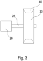
- the drive belt 38 is in a recess or groove 40 ( Figure 3 ) of the tension roller 30.
- the tensioning element 32 designed as a tension spring, generates a tensile force in a direction 33.
- the direction 33 corresponds to the longitudinal axis of the spring 32.
- the spring 32 is arranged such that the longitudinal axis 33 of the spring 32 is substantially perpendicular to a longitudinal axis 27 of the pivot lever 26.
- the longitudinal axis 27 is a connecting line between the central or rotational axis of the receiving element 28 carrying the tension roller 30 and the central or rotational axis of the holding element 24 carrying the pivot lever 26.
- the swivel axis 24 is mounted on two sides or fixed ( Figure 2 ). In this respect, two holding elements 22 are arranged on the underside 20 of the bottom bracket and/or motor housing 12.
- the distance between the pivot axis 24 and a rotation axis 21 of the bottom bracket is small.
- the distance is in the range of 5 to 15 cm and particularly preferably in the range of 7 to 12 cm.
- the tension roller 30 is held on one side by the roller axis 28, wherein preferably the roller axis 28 is firmly connected to the pivot lever 26 and the rotation of the tension roller 30 takes place at the free end, in particular by providing a ball bearing.
Landscapes
- Engineering & Computer Science (AREA)
- Mechanical Engineering (AREA)
- General Engineering & Computer Science (AREA)
- Chemical & Material Sciences (AREA)
- Combustion & Propulsion (AREA)
- Transportation (AREA)
- Devices For Conveying Motion By Means Of Endless Flexible Members (AREA)
Description
- Die Erfindung betrifft ein Fahrradrahmenelement mit einer Riemen-Spanneinrichtung für Antriebsriemen eines Fahrrads.
- Antriebsriemen oder auch Antriebsketten für Fahrräder längen sich aufgrund der bei der Benutzung auftretenden Kräfte. Dies führt dazu, dass der Antriebsriemen oder alternativ die Antriebskette regelmäßig gespannt werden muss. Dies erfolgt bei herkömmlichen Fahrrädern, beispielsweise durch ein entsprechendes Verschieben der Hinterradachse. Um ein Nachjustieren bzw. Nachspannen zu vermeiden, sind auch automatische Spanneinrichtungen bekannt, bei denen über Federelemente eine Spannrolle auf den Riemen oder die Kette gedrückt wird, um diese unter möglichst gleicher Spannung zu halten.
- Eine derartige Riemen-Spanneinrichtung ist beispielsweise aus
US 2014/0235388 bekannt. Eine Spannrolle ist über ein Hebelelement im Bereich der Hinterradachse mit dem Ausfallende verbunden. Parallel zu dem Hebelelement ist in montiertem Zustand unterhalb des Hebelelements eine Zugfeder vorgesehen, durch die die Spannrolle von unten gegen den Riemen gedrückt wird. Die inUS 2014/0235388 beschriebene Riemen-Spanneinrichtung weist den Nachteil auf, dass die Kräfte von der Feder nur zu einem geringen Teil auf die Spannrolle übertragen werden. Insofern muss eine relativ starke Feder eingesetzt werden. Ferner ist der Hebelmechanismus relativ kompliziert, um eine Zugfeder einsetzen zu können. - Eine weitere komplex aufgebaute Ketten-Spanneinrichtung ist aus
US 3,640,44 bekannt. Die Spannrolle drückt hierbei von oben auf den oberen Teil der Kette. Über ein Hebelelement und ein Befestigungselement ist diese Spanneinrichtung am Sattelrohr befestigt. Ferner ist zwischen dem Hebelelement und dem Sattelrohr eine Zugfeder vorgesehen. Auch bei dieser Vorrichtung kann nur ein Teil der von der Zugfeder aufgebrachten Kraft auf die Kette übertragen werden. - Weitere Ausgestaltungen und Anordnungen von Spannelementen sind aus
EP 2 746 143 bekannt. DieUS 5 618 240 offenbart die Merkmale des Oberbegriffes des Anspruchs 1. - Aufgabe der Erfindung ist es, ein Fahrradrahmenelement mit einer Riemen-Spanneinrichtung für Antriebsriemen eines Fahrrads zu schaffen, mit der ein zuverlässiges Spannen eines Riemens erzielt werden kann.
- Die Lösung der Aufgabe erfolgt erfindungsgemäß durch ein Fahrradrahmenelement mit einer Rahmen-Spanneinrichtung, gemäß Anspruch 1.
- Die Riemen-Spanneinrichtung ist selbstverständlich nicht nur für Riemen, sondern alternativ auch für Ketten oder andere entsprechende Antriebselemente geeignet.
- Im nachfolgenden wird die Erfindung anhand eines Antriebriemens erläutert.
- Die erfindungsgemäße Spanneinrichtung ist für Antriebsriemen eines Fahrrads, insbesondere eines Fahrrads mit Elektromotor, besonders gut geeignet. Insbesondere bei Fahrrädern mit elektromotorischer Unterstützung ist ein kontinuierlich gespannter Riemen oder dergleichen vorteilhaft. Die erfindungsgemäße Riemen-Spanneinrichtung weist eine Spannrolle auf. In montiertem Zustand drückt die Spannrolle vorzugsweise gegen eine Außenseite des Riemens. Besonders bevorzugt ist es, dass die Spannrolle gegen eine Unterseite des Riemens, d.h. einen Teil des Riemens, drückt, auf den in Betrieb keine Zugkräfte durch das Treten oder den Elektromotor wirken. Die Spannrolle ist mit einem Schwenkhebel verbunden. Die Verbindung erfolgt hier insbesondere über ein Aufnahmeelement, das die Spannrolle drehend trägt. Bei dem Aufnahmeelement handelt es sich insbesondere um eine Achse oder Welle, die die Spannrolle trägt. Das Aufnahmeelement kann einstückig mit dem Schwenkhebel ausgebildet sein. Der Schwenkhebel ist über ein Halteelement schwenkbar am Rahmen mittelbar oder unmittelbar befestigt. Bei dem Halteelement kann es sich insbesondere um eine Schwenkachse handeln, um die der Schwenkhebel schwenkbar mit dem Fahrradrahmen, ggf. über ein Zwischenelement, befestigt ist. Ferner ist ein Spannelement vorgesehen, das sowohl mit dem Schalthebel als auch mit dem Fahrradrahmen mittelbar oder unmittelbar verbunden ist. Erfindungsgemäß ist das Spannelement derart angeordnet, dass es mit dem Schwenkhebel zwischen dem Aufnahmeelement für die Spannrolle und dem Halteelement für den Schwenkhebel mit dem Schwenkhebel verbunden ist. Hierdurch ist eine sehr gute Kraftübertragung von dem Spannelement auf den Schwenkhebel und somit auf die Spannrolle realisiert.
- Besonders bevorzugt ist es, dass das Spannelement im Wesentlichen in der Mitte zwischen dem Halteelement und dem Aufnahmeelement angeordnet ist. Hierbei ist eine Abweichung von ± 10mm, insbesondere ± 5mm von der exakten Mitte möglich. Durch eine derartig, insbesondere mittige Verbindung, kann eine gute Kraftübertragung realisiert werden.
- Das Spannelement insbesondere mit dem Sattelrohr unmittelbar oder mittelbar, insbesondere über ein Befestigungs- oder Halteelement, befestigt. In Fahrtrichtung erfolgt die Befestigung am Sattelrohr, insbesondere auf der Rückseite des Sattelrohrs.
- Vorzugsweise handelt es sich bei dem Spannelement um ein elastisches Element, wobei das Spannelement ein elastisches Element aufweist und insbesondere als elastisches Element ausgebildet ist. Das Vorsehen eines elastischen Elements besteht darin, dass hierdurch ein selbstständiges automatisches Justieren erfolgt. Gegebenenfalls kann das Spannelement aber auch insbesondere zusätzlich zu dem elastischen Element eine justierbare Spanneinrichtung, eine Spannschraube oder dergleichen, aufweisen. Besonders bevorzugt ist es, dass das Spannelement eine Feder aufweist, sondern insbesondere als Feder ausgebildet ist. Gegebenenfalls kann eine derartige Feder mit einer Spannschraube zur Feinjustage verbunden sein. Vorzugsweise handelt es sich bei der Feder um eine Zugfeder, sodass das Spannelement eine Zugfeder aufweist und in besonders bevorzugter Form als Zugfeder ausgebildet ist.
- Gemäß der Erfindung erstreckt sich in montiertem Zustand das Spannelement insbesondere ausgehend vom Sattelrohr nach unten und ist zwischen den beiden Kettenstreben angeordnet . Die Kettenstreben sind hierbei diejenigen Streben, die am Ausfallende zur Aufnahme der Hinterradachse dienen und üblicherweise im Bereich des Tretlagers mit dem Fahrradrahmen, beispielsweise schwenkbar oder fest verbunden sind. Hierdurch ist eine sehr zentrale geschützte Anordnung des Spannelements möglich.
- In besonders bevorzugter Ausführungsform ist eine Längsachse des vorzugsweise als Zugfeder ausgebildeten Spannelements, im Wesentlichen senkrecht zu einer Längsachse des Schwenkhebels angeordnet. In montiertem Zustand ist es daher besonders bevorzugt, dass die Längsachse des Spannelements zur Längsachse des Schwenkhebels einen Winkel 90° ± 20°, insbesondere ± 15° und besonders bevorzugt ± 10°, aufweist. Die Längsachse des Spannelements entspricht der Kraft- bzw. Zugrichtung des Spannelements. Die Längsachse des Schwenkhebels ist vorzugsweise durch eine Verbindungslinie zwischen dem Aufnahmeelement und dem Halteelement ausgebildet. Da es sich bei dem Aufnahmeelement und dem Halteelement jeweils in bevorzugter Ausführungsform um Achsen oder Wellen handelt, ist die Verbindungslinie diejenige Linie, die die beiden Mittellinien des Aufnahmeelements sowie des Halteelements miteinander verbindet.
- Insbesondere wenn die Spanneinrichtung für Antriebsriemen ausgebildet ist, ist es bevorzugt, dass die Spannrolle eine umlaufende Vertiefung bzw. Nut zur Aufnahme bzw. Führung des Riemens aufweist.
- Des Weiteren ist es bevorzugt, dass das Aufnahmeelement der Spannrolle eine insbesondere fest mit dem Schwenkhebel verbundene Rollenachse aufweist, bzw. als Rollenachse ausgebildet ist. Hierdurch ist es auf einfache Weise möglich, eine Spannrolle, die insbesondere von einem Kugellager drehbar gehalten ist, anzuordnen. Vorzugsweise ist die Spannrolle seitlich neben dem Schwenkhebel angeordnet. In montiertem Zustand ist die vorzugsweise vorgesehene Rollenachse horizontal angeordnet. Insofern ist es bevorzugt, dass die Spannrolle einseitig gehalten ist.
- Das Halteelement, über das der Schwenkhebel mittelbar oder unmittelbar mit dem Fahrradrahmen verbunden ist, weist insbesondere eine Schwenkachse auf. Vorzugsweise ist die Schwenkachse über zwei Lagerelemente schwenkbar gelagert. Bei den Lagerelementen kann es sich um Öffnungen handeln, wobei vorzugsweise fett geschmierte Lager vorgesehen sind. Besonders bevorzugt ist es, dass der Schwenkhebel zwischen den beiden Lagenelementen angeordnet ist, sodass auf dem Schwenkhebel wirkende Kräfte gut aufgenommen werden können und insbesondere ein verkippen des Schwenkhebels vermieden ist. Alternativ kann die Schwenkachse auch fest angeordnet sein und die Drehung zwischen dem Schwenkhebel und der Schwenkachse erfolgen, wobei es sodann bevorzugt ist, dass in einer Öffnung des Schwenkhebels ein entsprechendes Lageelement vorgesehen ist. Insbesondere ist der Schwenkhebel mittig unterhalb des Sattelrohrs angeordnet, sodass das Spannelement in montiertem Zustand in einer vertikalen Ebene verläuft. Insofern ist es bevorzugt, dass sowohl das Spannelement als auch der Schwenkhebel in der Fahrradmittenebene angeordnet ist. Die Fahrradmittenebene ist die vertikale Symmetrieebene des Fahrrads.
- Des Weiteren ist es bevorzugt, dass das Halteelement, das insbesondere zweistückig ausgebildet ist und die Schwenkachse trägt, im Bereich eines Tretlager- und/oder Motorgehäuses angeordnet ist. Insbesondere ist das Halteelement mit einer Unterseite bzw. Hinterseite des Tretlager- und/oder Motorgehäuses fest verbunden.
- Vorzugsweise weist eine Schwenkachse bzw. Mittelachse des Halteelements zur Drehachse des Tretlagers einen geringen Abstand auf. Besonders bevorzugt ist es, dass dieser Abstand im Bereich von 5 bis 15 cm, insbesondere 7 bis 12 cm liegt.
- Des Weiteren betrifft die Erfindung ein Fahrradrahmenelement. Das Fahrradrahmenelement weist zumindest ein Sattelrohr und ein mit dem Sattelrohr verbundenes Tretlager- und/oder Motorgehäuse auf. Ferner kann das Fahrradrahmenelement die üblichen weiteren Elemente, wie Kettenstreben, Sattelstreben, Unterrohr, Oberrohr, Gabelrohr und dergleichen aufweisen. Bei dem erfindungsgemäßen Fahrradrahmenelement sind mit dem Sattelrohr und/oder dem Tretlager- und/oder Motorgehäuse ferner die beiden Kettenstreben verbunden. Des Weiteren ist erfindungsgemäß ein Riemenspannelement, wie vorstehend beschrieben, angeordnet und vorteilhaft weitergebildet.
- Nachfolgend wird die Erfindung anhand einer bevorzugten Ausführungsform unter Bezugnahme auf die anliegenden Zeichnungen näher erläutert.
- Es zeigen:
- Figuren 1
- eine schematische Seitenansicht eines Fahrradrahmenelements mit montiertem Riemen-Spannelement,
- Figur 2
- eine schematische Schnittansicht entlang der Linie II-II in
Figur 1 und - Figur 3
- eine schematische Ansicht in Richtung des Pfeils III in
Figur 1 . - In der vereinfachten schematischen Darstellung eines Fahrradrahmenelements in
Figur 1 ist ein Sattelrohr 10 mit einem Tretlager- und/oder Motorgehäuse 12 verbunden. Mit diesem ist ferner ein Unterrohr 14 eines Fahrradrahmenelements verbunden. Entgegen einer Fahrtrichtung 16 sind auf der Rückseite des Tretlager- und/oder Motorgehäuses 12 Kettenstreben 18 angeordnet, die im dargestellten Ausführungsbeispiel fest mit dem Tretlager- und/oder Motorgehäuse 12 verbunden sind. - An einer Unterseite 20 im rückwärtigen Bereich des Tretlager- und/oder Motorgehäuses 12 ist ein Verbindungselement 22 fest mit dem Tretlager- und/oder Motorgehäuse 12 verbunden. Über eine Schwenkachse 24 ist mit dem Halteelement 22 ein Schwenkhebel 26 schwenkbar verbunden. Der Schwenkhebel 26 trägt im dargestellten Ausführungsbeispiel über eine Schwenkachse 28 eine Spannrolle 30. Hierbei ist die Spannrolle 30 an dem entgegen der Fahrtrichtung 16 weisenden Ende des Schwenkhebels 26 mit diesem verbunden. Ferner ist in einem mittleren Bereich zwischen dem als Schwenkachse 24 ausgebildeten Halteelement und dem als Rollenachse 28 ausgebildeten Aufnahmeelement für die Spannrolle 30 ein Spannelement 32 angeordnet. Das im dargestellten Ausführungsbeispiel als Zugfeder ausgebildete Spannelement ist einerseits im mittleren Bereich des Schwenkhebels 26 mit diesem verbunden und andererseits über ein Halteelement 34 mit dem Sattelrohr 10 verbunden. Das Halteelement 34 ist hierbei bezogen auf eine Fahrtrichtung 36 an einer Rückseite des Sattelrohrs 10 angeordnet.
- Die Spannrolle 30 drückt aufgrund der von der Feder 32 aufgebrachten Zugkraft gegen eine Unterseite 36 eines schematisch dargestellten Antriebriemens 38. Hierbei ist der Antriebsriemen 38 in einer Vertiefung oder Nut 40 (
Figur 3 ) der Spannrolle 30 angeordnet. - Das als Zugfeder ausgebildete Spannelement 32 erzeugt eine Zugkraft in eine Richtung 33. Die Richtung 33 entspricht der Längsachse der Feder 32. In montiertem Zustand ist die Feder 32 derart angeordnet, dass die Längsachse 33 der Feder 32 im Wesentlichen senkrecht zu einer Längsachse 27 des Schwenkhebels 26 ist. Die Längsachse 27 ist eine Verbindungslinie zwischen der Mittel- bzw. Drehachse des die Spannrolle 30 tragenden Aufnahmeelements 28 sowie der Mittel- bzw. Drehachse des den Schwenkhebel 26 tragendenden Halteelements 24.
- Die Schwenkachse 24 ist zweiseitig gelagert, bzw. fixiert (
Figur 2 ). Insofern sind mit der Unterseite 20 des Tretlager- und/oder Motorgehäuses 12 zwei Halteelemente 22 angeordnet. - Vorzugsweise ist der Abstand zwischen der Schwenkachse 24 und einer Drehachse 21 des Tretlagers gering. Insbesondere liegt der Abstand im Bereich von 5 bis 15 cm und besonders bevorzugt im Bereich von 7 bis 12 cm. Diese tragen die Schwenkachse 24, wobei die Schwenkachse entweder fest mit den beiden Halteelementen 22 verbunden oder von diesen drehbar gehalten ist. In der Mitte zwischen den beiden Halteelementen 22 ist der Schwenkhebel 26 angeordnet.
- Die Spannrolle 30 ist über die Rollenachse 28 einseitig gehalten, wobei vorzugsweise die Rollenachse 28 fest mit dem Schwenkhebel 26 verbunden ist und die Drehung der Spannrolle 30 am freien Ende, insbesondere durch Vorsehen eines Kugellagers erfolgt.
Claims (13)
- Fahrradrahmenelement miteinem Sattelrohr (10), einem mit dem Sattelrohr (10) verbundenen Tretlager- und/oder Motorgehäuse (12) undmit dem Sattelrohr (10) und/oder dem Tretlager- und/oder Motorgehäuse (12) verbundenen Kettenstreben (18) sowieeiner Riemen-Spanneinrichtung für Antriebsriemen eines Fahrrads, mit einer Spannrolle (30),einem die Spannrolle (30) mittels eines Aufnahmeelements (28) drehbar tragenden Schwenkhebels (26),einem dem Schwenkhebel (26) schwenkbar tragenden Halteelement (24), das am Fahrradrahmen befestigbar ist undeinem mit dem Schwenkhebel (26) und dem Fahrradrahmen verbundenen Spannelement (32),wobei das Spannelement (32) mit dem Schwenkhebel (26) zwischen dem Halteelement (24) und dem Aufnahmeelement (28) verbunden ist dadurch gekennzeichnet, dassdas Spannelement (32) in montiertem Zustand zwischen Kettenstreben (18) undam Fahrradrahmen am Sattelrohr (10), insbesondere auf einer Rückseite des Sattelrohrs (10) angeordnet ist.
- Fahrradrahmenelement nach Anspruch 1, dadurch gekennzeichnet, dass das Spannelement (32) in der Mitte zwischen dem Halteelement (24) und dem Aufnahmeelement (28), insbesondere mit einer Abweichung von der Mitte von weniger als ± 10mm, vorzugsweise weniger als ± 5mm befestigt ist.
- Fahrradrahmenelement nach einem der Ansprüche 1 bis 2, dadurch gekennzeichnet, dass das Spannelement (32) ein elastisches Element aufweist, insbesondere als elastisches Element ausgebildet ist.
- Fahrradrahmenelement nach einem der Ansprüche 1 bis 3, dadurch gekennzeichnet, dass das Spannelement (32) eine Feder, insbesondere eine Zugfeder, aufweist, wobei das Spannelement (32) vorzugsweise als Feder, insbesondere als Zugfeder ausgebildet ist.
- Fahrradrahmenelement nach einem der Ansprüche 1 bis 4, dadurch gekennzeichnet, dass das Spannelement (32) auf einer Rückseite des Sattelrohrs (10) angeordnet ist.
- Fahrradrahmenelement nach einem der Ansprüche 1 bis 5, dadurch gekennzeichnet, dass eine Längsachse (33) des Spannelements (32) im wesentlichen senkrecht zu einer Längsachse (27) des Schwenkhebels (26) verläuft.
- Fahrradrahmenelement nach einem der Ansprüche 1 bis 6, dadurch gekennzeichnet, dass die Spannrolle (30) eine umlaufende Vertiefung (40) zur Aufnahme eines Riemens aufweist.
- Fahrradrahmenelement nach einem der Ansprüche 1 bis 7, dadurch gekennzeichnet, dass das Aufnahmeelement (28) der Spannrolle (30) eine insbesondere fest mit dem Schwenkhebel (26) verbundene Rollenachse (28) aufweist.
- Fahrradrahmenelement nach einem der Ansprüche 1 bis 8, dadurch gekennzeichnet, dass die Spannrolle (30) seitlich neben dem Schwenkhebel (26) angeordnet ist.
- Fahrradrahmenelement nach einem der Ansprüche 1 bis 9, dadurch gekennzeichnet, dass das Halteelement (24) eine Schwenkachse aufweist und insbesondere als Schwenkachse ausgebildet ist.
- Fahrradrahmenelement nach einem der Ansprüche 1 bis 10, dadurch gekennzeichnet, dass die Schwenkachse (24) über zwei Lagerelemente gelagert ist, wobei der Schwenkhebel (26) vorzugsweise zwischen den beiden Lagerelementen angeordnet ist.
- Fahrradrahmenelement nach einem der Ansprüche 1 bis 11, dadurch gekennzeichnet, dass das Halteelement (24) im Bereich eines Tretlager- und/oder Motorgehäuses angeordnet ist.
- Fahrradrahmenelement nach einem der Ansprüche 1 bis 12, dadurch gekennzeichnet, dass eine Schwenkachse des Halteelements 24 zu einer Drehachse (21) des Tretlagers einen Abstand von 5 bis 15 cm, insbesondere 7 bis 12 cm aufweist.
Applications Claiming Priority (2)
| Application Number | Priority Date | Filing Date | Title |
|---|---|---|---|
| DE202019104710.0U DE202019104710U1 (de) | 2019-08-28 | 2019-08-28 | Riemen-Spanneinrichtung |
| PCT/EP2020/073426 WO2021037692A1 (de) | 2019-08-28 | 2020-08-20 | Riemen-spanneinrichtung |
Publications (2)
| Publication Number | Publication Date |
|---|---|
| EP4007862A1 EP4007862A1 (de) | 2022-06-08 |
| EP4007862B1 true EP4007862B1 (de) | 2024-08-28 |
Family
ID=72193461
Family Applications (1)
| Application Number | Title | Priority Date | Filing Date |
|---|---|---|---|
| EP20760830.8A Active EP4007862B1 (de) | 2019-08-28 | 2020-08-20 | Riemen-spanneinrichtung |
Country Status (4)
| Country | Link |
|---|---|
| EP (1) | EP4007862B1 (de) |
| DE (1) | DE202019104710U1 (de) |
| DK (1) | DK4007862T3 (de) |
| WO (1) | WO2021037692A1 (de) |
Citations (2)
| Publication number | Priority date | Publication date | Assignee | Title |
|---|---|---|---|---|
| US5618240A (en) * | 1995-06-07 | 1997-04-08 | Gilbert; Raymond D. | Sprocket ratio changer |
| WO2003064243A1 (en) * | 2002-01-29 | 2003-08-07 | Karel Hladik | Bicycle chain drive |
Family Cites Families (8)
| Publication number | Priority date | Publication date | Assignee | Title |
|---|---|---|---|---|
| GB191214825A (en) * | 1912-06-25 | 1913-02-13 | Joergen Otto Joergensen | Improved Device for Tensioning Chains. |
| JPS5135935A (ja) * | 1974-09-18 | 1976-03-26 | Okuma Atsutaka | Hensokusochi |
| CN2686983Y (zh) * | 2004-02-09 | 2005-03-23 | 孙广先 | 人力脚踏式无级变速自行车 |
| DE202005002842U1 (de) * | 2005-02-22 | 2005-05-19 | Motive Power Industry Co., Ltd., Dacun | Geländemotorrad-Kettenspanner |
| US20120252614A1 (en) * | 2011-03-31 | 2012-10-04 | Tai-Her Yang | Treadle-drive eccentric wheel transmission wheel series with periodically varied speed ratio |
| US9169903B2 (en) * | 2012-12-18 | 2015-10-27 | Tai-Her Yang | Transmission wheel system series with periodically varied speed ratio and having reciprocally displacing auxiliary pulley for storing/releasing kinetic energy |
| US20140235388A1 (en) * | 2013-02-21 | 2014-08-21 | Wen-Pin Chang | Mechanism for adjusting tension of belt of a bicycle |
| US10486770B2 (en) * | 2016-06-30 | 2019-11-26 | Shimano Inc. | Bicycle tensioner apparatus and bicycle tensioner |
-
2019
- 2019-08-28 DE DE202019104710.0U patent/DE202019104710U1/de active Active
-
2020
- 2020-08-20 DK DK20760830.8T patent/DK4007862T3/da active
- 2020-08-20 EP EP20760830.8A patent/EP4007862B1/de active Active
- 2020-08-20 WO PCT/EP2020/073426 patent/WO2021037692A1/de not_active Ceased
Patent Citations (2)
| Publication number | Priority date | Publication date | Assignee | Title |
|---|---|---|---|---|
| US5618240A (en) * | 1995-06-07 | 1997-04-08 | Gilbert; Raymond D. | Sprocket ratio changer |
| WO2003064243A1 (en) * | 2002-01-29 | 2003-08-07 | Karel Hladik | Bicycle chain drive |
Also Published As
| Publication number | Publication date |
|---|---|
| WO2021037692A1 (de) | 2021-03-04 |
| EP4007862A1 (de) | 2022-06-08 |
| DE202019104710U1 (de) | 2020-12-02 |
| DK4007862T3 (da) | 2024-10-21 |
Similar Documents
| Publication | Publication Date | Title |
|---|---|---|
| EP0662419B1 (de) | Fahrrad-Vorderradkabel aus einem Verbundwerkstoff | |
| EP2337704B1 (de) | Untergestell eines kraftfahrzeugsitzes mit zwei schienenpaaren, schwingen und einem sitzträger | |
| DE102008064057B4 (de) | Fahrradkettenumwerfer mit mehreren Montageeinstellungen | |
| DE3508776C2 (de) | Stoßdämfpungseinrichtung zur Verwendung bei einem Fahrzeugsitz | |
| DE19512016A1 (de) | Fahrradsitz | |
| DE10145843A1 (de) | Kraftfahzeugsitz | |
| EP4155176B1 (de) | Kettenstreben-schutzelement sowie kettenstreben-system | |
| EP1599370B1 (de) | Vorrichtung zum befestigen eines gurtschlosses eines sicherheitsgurtes an einem fahrzeugsitz | |
| DE3221011A1 (de) | Walze | |
| EP4007862B1 (de) | Riemen-spanneinrichtung | |
| DE10044851C2 (de) | Kraftfahrzeugsitz | |
| DE9204330U1 (de) | Tretkurbeltrieb für Fahrräder oder dergleichen | |
| EP3954600B1 (de) | Seilzug-lenkscheibe | |
| DE2108441A1 (de) | Zeichenmaschine | |
| EP3786038B1 (de) | Fahrrad-sattelstütze | |
| DE3013854A1 (de) | Kettenschaltung mit automatischer seillaengenkompensation | |
| EP0387382B1 (de) | Kurbelgetriebe für Fahrräder, Dreiräder oder dergleichen | |
| DE2903736A1 (de) | Fahrrad-kettenschaltung | |
| DE10058017A1 (de) | Kraftfahrzeugsitz | |
| CH677471A5 (en) | Bicycle handlebars - have clamp adjustable for angle on pivot head by further clamp with locking faces | |
| DE3831890C2 (de) | ||
| DE3120552A1 (de) | Fahrrad | |
| AT39082B (de) | Rübenerntemaschine. | |
| DE202023101480U1 (de) | Seilzug-Lenkscheibe | |
| DE19738454C1 (de) | Höhenverstelleinrichtung für einen Tisch |
Legal Events
| Date | Code | Title | Description |
|---|---|---|---|
| STAA | Information on the status of an ep patent application or granted ep patent |
Free format text: STATUS: UNKNOWN |
|
| STAA | Information on the status of an ep patent application or granted ep patent |
Free format text: STATUS: THE INTERNATIONAL PUBLICATION HAS BEEN MADE |
|
| PUAI | Public reference made under article 153(3) epc to a published international application that has entered the european phase |
Free format text: ORIGINAL CODE: 0009012 |
|
| STAA | Information on the status of an ep patent application or granted ep patent |
Free format text: STATUS: REQUEST FOR EXAMINATION WAS MADE |
|
| 17P | Request for examination filed |
Effective date: 20220301 |
|
| AK | Designated contracting states |
Kind code of ref document: A1 Designated state(s): AL AT BE BG CH CY CZ DE DK EE ES FI FR GB GR HR HU IE IS IT LI LT LU LV MC MK MT NL NO PL PT RO RS SE SI SK SM TR |
|
| DAV | Request for validation of the european patent (deleted) | ||
| DAX | Request for extension of the european patent (deleted) | ||
| STAA | Information on the status of an ep patent application or granted ep patent |
Free format text: STATUS: EXAMINATION IS IN PROGRESS |
|
| 17Q | First examination report despatched |
Effective date: 20230728 |
|
| GRAP | Despatch of communication of intention to grant a patent |
Free format text: ORIGINAL CODE: EPIDOSNIGR1 |
|
| STAA | Information on the status of an ep patent application or granted ep patent |
Free format text: STATUS: GRANT OF PATENT IS INTENDED |
|
| INTG | Intention to grant announced |
Effective date: 20240412 |
|
| GRAS | Grant fee paid |
Free format text: ORIGINAL CODE: EPIDOSNIGR3 |
|
| GRAA | (expected) grant |
Free format text: ORIGINAL CODE: 0009210 |
|
| STAA | Information on the status of an ep patent application or granted ep patent |
Free format text: STATUS: THE PATENT HAS BEEN GRANTED |
|
| AK | Designated contracting states |
Kind code of ref document: B1 Designated state(s): AL AT BE BG CH CY CZ DE DK EE ES FI FR GB GR HR HU IE IS IT LI LT LU LV MC MK MT NL NO PL PT RO RS SE SI SK SM TR |
|
| REG | Reference to a national code |
Ref country code: CH Ref legal event code: EP |
|
| REG | Reference to a national code |
Ref country code: DE Ref legal event code: R096 Ref document number: 502020009050 Country of ref document: DE |
|
| REG | Reference to a national code |
Ref country code: IE Ref legal event code: FG4D Free format text: LANGUAGE OF EP DOCUMENT: GERMAN |
|
| P01 | Opt-out of the competence of the unified patent court (upc) registered |
Free format text: CASE NUMBER: APP_48807/2024 Effective date: 20240827 |
|
| REG | Reference to a national code |
Ref country code: NL Ref legal event code: FP |
|
| REG | Reference to a national code |
Ref country code: DK Ref legal event code: T3 Effective date: 20241018 |
|
| REG | Reference to a national code |
Ref country code: LT Ref legal event code: MG9D |
|
| PG25 | Lapsed in a contracting state [announced via postgrant information from national office to epo] |
Ref country code: NO Free format text: LAPSE BECAUSE OF FAILURE TO SUBMIT A TRANSLATION OF THE DESCRIPTION OR TO PAY THE FEE WITHIN THE PRESCRIBED TIME-LIMIT Effective date: 20241128 |
|
| PG25 | Lapsed in a contracting state [announced via postgrant information from national office to epo] |
Ref country code: PT Free format text: LAPSE BECAUSE OF FAILURE TO SUBMIT A TRANSLATION OF THE DESCRIPTION OR TO PAY THE FEE WITHIN THE PRESCRIBED TIME-LIMIT Effective date: 20241230 Ref country code: GR Free format text: LAPSE BECAUSE OF FAILURE TO SUBMIT A TRANSLATION OF THE DESCRIPTION OR TO PAY THE FEE WITHIN THE PRESCRIBED TIME-LIMIT Effective date: 20241129 Ref country code: PL Free format text: LAPSE BECAUSE OF FAILURE TO SUBMIT A TRANSLATION OF THE DESCRIPTION OR TO PAY THE FEE WITHIN THE PRESCRIBED TIME-LIMIT Effective date: 20240828 Ref country code: FI Free format text: LAPSE BECAUSE OF FAILURE TO SUBMIT A TRANSLATION OF THE DESCRIPTION OR TO PAY THE FEE WITHIN THE PRESCRIBED TIME-LIMIT Effective date: 20240828 |
|
| PG25 | Lapsed in a contracting state [announced via postgrant information from national office to epo] |
Ref country code: BG Free format text: LAPSE BECAUSE OF FAILURE TO SUBMIT A TRANSLATION OF THE DESCRIPTION OR TO PAY THE FEE WITHIN THE PRESCRIBED TIME-LIMIT Effective date: 20240828 |
|
| PG25 | Lapsed in a contracting state [announced via postgrant information from national office to epo] |
Ref country code: LV Free format text: LAPSE BECAUSE OF FAILURE TO SUBMIT A TRANSLATION OF THE DESCRIPTION OR TO PAY THE FEE WITHIN THE PRESCRIBED TIME-LIMIT Effective date: 20240828 |
|
| PG25 | Lapsed in a contracting state [announced via postgrant information from national office to epo] |
Ref country code: IS Free format text: LAPSE BECAUSE OF FAILURE TO SUBMIT A TRANSLATION OF THE DESCRIPTION OR TO PAY THE FEE WITHIN THE PRESCRIBED TIME-LIMIT Effective date: 20241228 |
|
| PG25 | Lapsed in a contracting state [announced via postgrant information from national office to epo] |
Ref country code: HR Free format text: LAPSE BECAUSE OF FAILURE TO SUBMIT A TRANSLATION OF THE DESCRIPTION OR TO PAY THE FEE WITHIN THE PRESCRIBED TIME-LIMIT Effective date: 20240828 |
|
| PG25 | Lapsed in a contracting state [announced via postgrant information from national office to epo] |
Ref country code: ES Free format text: LAPSE BECAUSE OF FAILURE TO SUBMIT A TRANSLATION OF THE DESCRIPTION OR TO PAY THE FEE WITHIN THE PRESCRIBED TIME-LIMIT Effective date: 20240828 Ref country code: RS Free format text: LAPSE BECAUSE OF FAILURE TO SUBMIT A TRANSLATION OF THE DESCRIPTION OR TO PAY THE FEE WITHIN THE PRESCRIBED TIME-LIMIT Effective date: 20241128 |
|
| PG25 | Lapsed in a contracting state [announced via postgrant information from national office to epo] |
Ref country code: RS Free format text: LAPSE BECAUSE OF FAILURE TO SUBMIT A TRANSLATION OF THE DESCRIPTION OR TO PAY THE FEE WITHIN THE PRESCRIBED TIME-LIMIT Effective date: 20241128 Ref country code: PT Free format text: LAPSE BECAUSE OF FAILURE TO SUBMIT A TRANSLATION OF THE DESCRIPTION OR TO PAY THE FEE WITHIN THE PRESCRIBED TIME-LIMIT Effective date: 20241230 Ref country code: PL Free format text: LAPSE BECAUSE OF FAILURE TO SUBMIT A TRANSLATION OF THE DESCRIPTION OR TO PAY THE FEE WITHIN THE PRESCRIBED TIME-LIMIT Effective date: 20240828 Ref country code: NO Free format text: LAPSE BECAUSE OF FAILURE TO SUBMIT A TRANSLATION OF THE DESCRIPTION OR TO PAY THE FEE WITHIN THE PRESCRIBED TIME-LIMIT Effective date: 20241128 Ref country code: LV Free format text: LAPSE BECAUSE OF FAILURE TO SUBMIT A TRANSLATION OF THE DESCRIPTION OR TO PAY THE FEE WITHIN THE PRESCRIBED TIME-LIMIT Effective date: 20240828 Ref country code: IS Free format text: LAPSE BECAUSE OF FAILURE TO SUBMIT A TRANSLATION OF THE DESCRIPTION OR TO PAY THE FEE WITHIN THE PRESCRIBED TIME-LIMIT Effective date: 20241228 Ref country code: HR Free format text: LAPSE BECAUSE OF FAILURE TO SUBMIT A TRANSLATION OF THE DESCRIPTION OR TO PAY THE FEE WITHIN THE PRESCRIBED TIME-LIMIT Effective date: 20240828 Ref country code: GR Free format text: LAPSE BECAUSE OF FAILURE TO SUBMIT A TRANSLATION OF THE DESCRIPTION OR TO PAY THE FEE WITHIN THE PRESCRIBED TIME-LIMIT Effective date: 20241129 Ref country code: FI Free format text: LAPSE BECAUSE OF FAILURE TO SUBMIT A TRANSLATION OF THE DESCRIPTION OR TO PAY THE FEE WITHIN THE PRESCRIBED TIME-LIMIT Effective date: 20240828 Ref country code: ES Free format text: LAPSE BECAUSE OF FAILURE TO SUBMIT A TRANSLATION OF THE DESCRIPTION OR TO PAY THE FEE WITHIN THE PRESCRIBED TIME-LIMIT Effective date: 20240828 Ref country code: BG Free format text: LAPSE BECAUSE OF FAILURE TO SUBMIT A TRANSLATION OF THE DESCRIPTION OR TO PAY THE FEE WITHIN THE PRESCRIBED TIME-LIMIT Effective date: 20240828 |
|
| PG25 | Lapsed in a contracting state [announced via postgrant information from national office to epo] |
Ref country code: RO Free format text: LAPSE BECAUSE OF FAILURE TO SUBMIT A TRANSLATION OF THE DESCRIPTION OR TO PAY THE FEE WITHIN THE PRESCRIBED TIME-LIMIT Effective date: 20240828 Ref country code: SM Free format text: LAPSE BECAUSE OF FAILURE TO SUBMIT A TRANSLATION OF THE DESCRIPTION OR TO PAY THE FEE WITHIN THE PRESCRIBED TIME-LIMIT Effective date: 20240828 |
|
| PG25 | Lapsed in a contracting state [announced via postgrant information from national office to epo] |
Ref country code: EE Free format text: LAPSE BECAUSE OF FAILURE TO SUBMIT A TRANSLATION OF THE DESCRIPTION OR TO PAY THE FEE WITHIN THE PRESCRIBED TIME-LIMIT Effective date: 20240828 |
|
| PG25 | Lapsed in a contracting state [announced via postgrant information from national office to epo] |
Ref country code: CZ Free format text: LAPSE BECAUSE OF FAILURE TO SUBMIT A TRANSLATION OF THE DESCRIPTION OR TO PAY THE FEE WITHIN THE PRESCRIBED TIME-LIMIT Effective date: 20240828 |
|
| PG25 | Lapsed in a contracting state [announced via postgrant information from national office to epo] |
Ref country code: SK Free format text: LAPSE BECAUSE OF FAILURE TO SUBMIT A TRANSLATION OF THE DESCRIPTION OR TO PAY THE FEE WITHIN THE PRESCRIBED TIME-LIMIT Effective date: 20240828 Ref country code: IT Free format text: LAPSE BECAUSE OF FAILURE TO SUBMIT A TRANSLATION OF THE DESCRIPTION OR TO PAY THE FEE WITHIN THE PRESCRIBED TIME-LIMIT Effective date: 20240828 |
|
| REG | Reference to a national code |
Ref country code: DE Ref legal event code: R097 Ref document number: 502020009050 Country of ref document: DE |
|
| PLBE | No opposition filed within time limit |
Free format text: ORIGINAL CODE: 0009261 |
|
| STAA | Information on the status of an ep patent application or granted ep patent |
Free format text: STATUS: NO OPPOSITION FILED WITHIN TIME LIMIT |
|
| 26N | No opposition filed |
Effective date: 20250530 |
|
| PG25 | Lapsed in a contracting state [announced via postgrant information from national office to epo] |
Ref country code: SE Free format text: LAPSE BECAUSE OF FAILURE TO SUBMIT A TRANSLATION OF THE DESCRIPTION OR TO PAY THE FEE WITHIN THE PRESCRIBED TIME-LIMIT Effective date: 20240828 |
|
| PGFP | Annual fee paid to national office [announced via postgrant information from national office to epo] |
Ref country code: NL Payment date: 20250821 Year of fee payment: 6 |
|
| PGFP | Annual fee paid to national office [announced via postgrant information from national office to epo] |
Ref country code: DE Payment date: 20250717 Year of fee payment: 6 Ref country code: DK Payment date: 20250821 Year of fee payment: 6 |
|
| PGFP | Annual fee paid to national office [announced via postgrant information from national office to epo] |
Ref country code: GB Payment date: 20250822 Year of fee payment: 6 |
|
| PGFP | Annual fee paid to national office [announced via postgrant information from national office to epo] |
Ref country code: FR Payment date: 20250821 Year of fee payment: 6 |
|
| REG | Reference to a national code |
Ref country code: CH Ref legal event code: H13 Free format text: ST27 STATUS EVENT CODE: U-0-0-H10-H13 (AS PROVIDED BY THE NATIONAL OFFICE) Effective date: 20260324 |
|
| PG25 | Lapsed in a contracting state [announced via postgrant information from national office to epo] |
Ref country code: MC Free format text: LAPSE BECAUSE OF FAILURE TO SUBMIT A TRANSLATION OF THE DESCRIPTION OR TO PAY THE FEE WITHIN THE PRESCRIBED TIME-LIMIT Effective date: 20240828 |
|
| PG25 | Lapsed in a contracting state [announced via postgrant information from national office to epo] |
Ref country code: LU Free format text: LAPSE BECAUSE OF NON-PAYMENT OF DUE FEES Effective date: 20250820 |