EP4007865B1 - Géométrie de filetage hybride pour raccord fileté - Google Patents
Géométrie de filetage hybride pour raccord fileté Download PDFInfo
- Publication number
- EP4007865B1 EP4007865B1 EP20757217.3A EP20757217A EP4007865B1 EP 4007865 B1 EP4007865 B1 EP 4007865B1 EP 20757217 A EP20757217 A EP 20757217A EP 4007865 B1 EP4007865 B1 EP 4007865B1
- Authority
- EP
- European Patent Office
- Prior art keywords
- threads
- threaded fitting
- thread
- fitting according
- diameter
- Prior art date
- Legal status (The legal status is an assumption and is not a legal conclusion. Google has not performed a legal analysis and makes no representation as to the accuracy of the status listed.)
- Active
Links
Images



Classifications
-
- F—MECHANICAL ENGINEERING; LIGHTING; HEATING; WEAPONS; BLASTING
- F16—ENGINEERING ELEMENTS AND UNITS; GENERAL MEASURES FOR PRODUCING AND MAINTAINING EFFECTIVE FUNCTIONING OF MACHINES OR INSTALLATIONS; THERMAL INSULATION IN GENERAL
- F16B—DEVICES FOR FASTENING OR SECURING CONSTRUCTIONAL ELEMENTS OR MACHINE PARTS TOGETHER, e.g. NAILS, BOLTS, CIRCLIPS, CLAMPS, CLIPS OR WEDGES; JOINTS OR JOINTING
- F16B33/00—Features common to bolt and nut
- F16B33/004—Sealing; Insulation
-
- F—MECHANICAL ENGINEERING; LIGHTING; HEATING; WEAPONS; BLASTING
- F16—ENGINEERING ELEMENTS AND UNITS; GENERAL MEASURES FOR PRODUCING AND MAINTAINING EFFECTIVE FUNCTIONING OF MACHINES OR INSTALLATIONS; THERMAL INSULATION IN GENERAL
- F16B—DEVICES FOR FASTENING OR SECURING CONSTRUCTIONAL ELEMENTS OR MACHINE PARTS TOGETHER, e.g. NAILS, BOLTS, CIRCLIPS, CLAMPS, CLIPS OR WEDGES; JOINTS OR JOINTING
- F16B33/00—Features common to bolt and nut
- F16B33/02—Shape of thread; Special thread-forms
-
- F—MECHANICAL ENGINEERING; LIGHTING; HEATING; WEAPONS; BLASTING
- F16—ENGINEERING ELEMENTS AND UNITS; GENERAL MEASURES FOR PRODUCING AND MAINTAINING EFFECTIVE FUNCTIONING OF MACHINES OR INSTALLATIONS; THERMAL INSULATION IN GENERAL
- F16L—PIPES; JOINTS OR FITTINGS FOR PIPES; SUPPORTS FOR PIPES, CABLES OR PROTECTIVE TUBING; MEANS FOR THERMAL INSULATION IN GENERAL
- F16L15/00—Screw-threaded joints; Forms of screw-threads for such joints
- F16L15/001—Screw-threaded joints; Forms of screw-threads for such joints with conical threads
-
- F—MECHANICAL ENGINEERING; LIGHTING; HEATING; WEAPONS; BLASTING
- F16—ENGINEERING ELEMENTS AND UNITS; GENERAL MEASURES FOR PRODUCING AND MAINTAINING EFFECTIVE FUNCTIONING OF MACHINES OR INSTALLATIONS; THERMAL INSULATION IN GENERAL
- F16L—PIPES; JOINTS OR FITTINGS FOR PIPES; SUPPORTS FOR PIPES, CABLES OR PROTECTIVE TUBING; MEANS FOR THERMAL INSULATION IN GENERAL
- F16L15/00—Screw-threaded joints; Forms of screw-threads for such joints
- F16L15/006—Screw-threaded joints; Forms of screw-threads for such joints with straight threads
-
- F—MECHANICAL ENGINEERING; LIGHTING; HEATING; WEAPONS; BLASTING
- F16—ENGINEERING ELEMENTS AND UNITS; GENERAL MEASURES FOR PRODUCING AND MAINTAINING EFFECTIVE FUNCTIONING OF MACHINES OR INSTALLATIONS; THERMAL INSULATION IN GENERAL
- F16L—PIPES; JOINTS OR FITTINGS FOR PIPES; SUPPORTS FOR PIPES, CABLES OR PROTECTIVE TUBING; MEANS FOR THERMAL INSULATION IN GENERAL
- F16L41/00—Branching pipes; Joining pipes to walls
- F16L41/08—Joining pipes to walls or pipes, the joined pipe axis being perpendicular to the plane of a wall or to the axis of another pipe
- F16L41/14—Joining pipes to walls or pipes, the joined pipe axis being perpendicular to the plane of a wall or to the axis of another pipe by screwing an intermediate part against the inside or outside of the wall
-
- F—MECHANICAL ENGINEERING; LIGHTING; HEATING; WEAPONS; BLASTING
- F16—ENGINEERING ELEMENTS AND UNITS; GENERAL MEASURES FOR PRODUCING AND MAINTAINING EFFECTIVE FUNCTIONING OF MACHINES OR INSTALLATIONS; THERMAL INSULATION IN GENERAL
- F16L—PIPES; JOINTS OR FITTINGS FOR PIPES; SUPPORTS FOR PIPES, CABLES OR PROTECTIVE TUBING; MEANS FOR THERMAL INSULATION IN GENERAL
- F16L5/00—Devices for use where pipes, cables or protective tubing pass through walls or partitions
- F16L5/02—Sealing
- F16L5/06—Sealing by means of a swivel nut compressing a ring or sleeve
-
- H—ELECTRICITY
- H02—GENERATION; CONVERSION OR DISTRIBUTION OF ELECTRIC POWER
- H02G—INSTALLATION OF ELECTRIC CABLES OR LINES, OR OF COMBINED OPTICAL AND ELECTRIC CABLES OR LINES
- H02G3/00—Installations of electric cables or lines or protective tubing therefor in or on buildings, equivalent structures or vehicles
- H02G3/02—Details
- H02G3/06—Joints for connecting lengths of protective tubing or channels, to each other or to casings, e.g. to distribution boxes; Ensuring electrical continuity in the joint
- H02G3/0616—Joints for connecting tubing to casing
- H02G3/0625—Joints for connecting tubing to casing with means for preventing disengagement of conductors
- H02G3/0675—Joints for connecting tubing to casing with means for preventing disengagement of conductors with bolts operating in a direction parallel to the conductors
-
- F—MECHANICAL ENGINEERING; LIGHTING; HEATING; WEAPONS; BLASTING
- F16—ENGINEERING ELEMENTS AND UNITS; GENERAL MEASURES FOR PRODUCING AND MAINTAINING EFFECTIVE FUNCTIONING OF MACHINES OR INSTALLATIONS; THERMAL INSULATION IN GENERAL
- F16L—PIPES; JOINTS OR FITTINGS FOR PIPES; SUPPORTS FOR PIPES, CABLES OR PROTECTIVE TUBING; MEANS FOR THERMAL INSULATION IN GENERAL
- F16L5/00—Devices for use where pipes, cables or protective tubing pass through walls or partitions
- F16L5/02—Sealing
- F16L5/04—Sealing to form a firebreak device
Definitions
- This disclosure relates to thread profile geometry, and, more particularly, to a new and useful thread configuration for a locknut enabling its use in National Pipe Taper (NPT), British Standard Pipe Taper thread (BSPT), National pipe straight-mechanical (NPSM), National pipe straight-locknut (NPSL), British Standard Pipe Parallel thread (BSPP) , and unthreaded applications.
- NPT National Pipe Taper
- BSPT British Standard Pipe Taper thread
- NPSM National pipe straight-mechanical
- NPSL National pipe straight-locknut
- BSPP British Standard Pipe Parallel thread
- Hazardous locations may be found in occupancies such as aircraft hangars, gasoline/service stations, bulk storage plants for volatile flammable liquids, paint-finishing plants, health care facilities, agricultural facilities storing harvested grain in storage silos, marinas, boat yards, and petroleum processing plants. Each room, section or area is typically evaluated separately when determining its classification and the precautions which must be taken.
- pressure vessels containing natural gas may be held within a storage area having walls of a particular thickness to prevent fragments from inadvertently harming personnel in a surrounding area should an explosive event occur.
- piping or conduit leading into or out of the enclosure will often require a bladder, sheath, or other device to capture or prevent the leakage of the volatile gas out of the enclosure and into the surrounding area.
- This often includes standards for threaded apertures which accept the passage of the pipe or conduit. For example, it is common to seal pipe threads traversing the walls of the storage container, whether such walls be thin- or thick-walled containers.
- a variety of industry standards exist for such threaded connections including UL 2225, 1910.307, NEC 505 -10, and IEC EN 60079-1 Explosion Proof.
- US 2355403 A discloses a terminator, and more particularly a cable entrance bushing for connecting a sheathed electrical conductor through the wall of an entrance.
- US 2011/042935 A1 discloses a conduit/piping sump penetration fitting.
- the conduit/piping sump penetration fitting may comprise a bulk head fitting which does not require a plurality of mounting holes to mount the bulk head fitting to a sump wall. Rather, the bulk head fitting has a flange and a threaded portion. Opposed sides of the sump wall may have a rubber gasket through which the threaded portion is fed.
- a compression flange and compression nut compress the rubber gaskets onto the sump wall so as to form a fluid tight seal between the bulk head fitting and the sump wall.
- the threaded portion may have an internal beveled surface at its distal end portion which receives an o-ring.
- a conduit/piping is disposed in the bulk head fitting with the o-ring disposed about the conduit/piping.
- a second compression nut is threaded onto the threaded portion of the bulk head fitting which pushes the o-ring further down the internal beveled surface. This action causes the o-ring to compress upon the conduit/piping and form a fluid tight seal between the o-ring with the internal beveled surface and the conduit/piping exterior surface.
- US 2007/284876 A1 discloses a process and apparatus for internally reinstating a connection in a lined conduit.
- the connection may be a branch pipe or corporation stop that may or may not protrude into the conduit. It may be milled prior to lining.
- the process includes the step of locating the connection visually or with a probe; forming at an opening in the lining at the connection and then installing a T-nut with a sealing gasket facing the liner to hold the liner in place and form a seal between the T-nut and liner and the connection.
- the apparatus includes a motor coupled to a turntable with drive to install the T-nut and a supply of T-nuts mounted on a slide for loading the T-nuts onto the drive for installation of the T-nuts without having to remove the assembly between each installation.
- US 3994516 A discloses a threaded interconnect structure incorporating respective matching internal and external threaded portions of members to be threadedly interconnected, with the thread geometry defining a profile having contiguous straight-thread and tapered-thread sections.
- Tapered sections have a taper in excess of standard taper-threaded profiles and comprise comparatively fewer threads, with the sealing action in the tapered section being mechanically aided by the straight-thread sections during make-up of the joint, and thereafter mechanically reinforced by the straight-thread sections.
- a threaded fitting according to claim 1 is provided.
- a method for fabricating a hybrid threaded fitting according to claim 12 is provided.
- fitting means any device, coupling, connector, adaptor, joint, or attachment configured to join a conduit, pipe, cable, or wiring harness in combination with a thin- or thick-walled enclosure.
- Atex Directive 2014/34/EU A uniform classification of hazardous areas (installations) provides a basis for selecting and assigning systems and devices including their installation.
- EU Directive 1999/92/EC an explosion protection document is a precondition for setting up and operating a potentially explosive facility.
- lock-nuts have become particularly relevant for augmenting the performance of threaded fittings, especially those exposed to a continuous source of vibration.
- Lock-nuts are used in combination with parallel threads inasmuch as the root diameter of such threads does not decrease as the lock-nut rotates in a direction tending to loosen the nut. That is, once the lock-nut plastically deforms into the root diameter of the threads, the threads remain deformed as vibration causes the lock-nut to rotate.
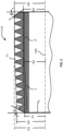
- FIGS. 1 and 2 depict a threaded fitting 10 having a first plurality of threads T, a second plurality of threads S, and at least one transition thread TT disposed therebetween.
- the first plurality of threads T is configured to provide a labyrinth-type seal for minimizing the migration of at least hazardous dust and/or gases across thick-walled enclosures. More specifically, the first plurality of threads T have a root diameter D1 which tapers from the transition thread TT to a reference plane zero R 0 .
- the crest diameter D2 of the first plurality of threads T also tapers from the transition thread TT to a reference plane zero R 0 .
- the crest diameter D3 of the first plurality of threads T forms a straight angle or is parallel to the elongate axis 10A of the threaded fitting 10.
- the crest diameter D3 is equal to the crest diameter D6 of the second plurality of threads S.
- the root and crest diameters D1, D2 of the first plurality of threads T may taper along an angle ⁇ of between about one degree (1°) to about two and one quarter degrees (2 1/4°) relative to the elongate axis 10A of the threaded fitting 10.
- the cone angle is twice the value of angle alpha ⁇ and may vary from two degrees (2°) to about four and one half degrees (4 1/2).
- the taper of the crest diameter is preferably the same as the taper of the root diameter or between about one degree (1°) to about two and one quarter degrees (2 1/4°) relative to the elongate axis 10A of the threaded fitting 10.
- the root diameter taper of the first plurality T is between about one and twelve sixteenths degrees (1 12/16ths°), i.e., one and three quarter degrees (1 3/4°) to about one and thirteen sixteenths degrees (1 13/16ths).
- the root diameter angle ⁇ is about one and seventy-eight hundredths degrees (1.78°) to about one and one hundred eighty eight thousandths degrees (1.188°) and the cone angle is three and fifty eight hundredths degrees (3.58°).
- the root and crest diameters D1, D2 of the first plurality of threads T taper along a cone angle ⁇ of about one and one eighth degrees (1 1/8°) relative to the elongate axis 10A of the threaded fitting 10.
- the second plurality of threads S is configured to provide a labyrinth-type seal for minimizing the migration of at least water/fluids across thin-walled enclosures.
- the second plurality of threads S have root and crest diameters, D4 and D6, respectively, which are straight or parallel relative to the elongate axis 10A of the threaded fitting 10.
- the threaded fitting 10 also includes at least one (1) transition thread disposed between the first and second plurality of threads T, S.
- the transition thread has a root diameter D5 which is equal to the root diameter D4 of the second plurality of threads S and a crest diameter D3 which is equal to the crest diameter D6 of the second plurality of threads S.
- the threaded fitting 10 includes between four (4) and six (6) threads in each of the first and second plurality of threads T, S.
- the illustrated embodiment depicts five (5) tapering threads in the first plurality of threads T, and five (5) straight or parallel threads in the second plurality of threads S.
- the at least one transition thread TT changes the profile of the thread from a tapering thread in the first plurality of threads T to a straight thread in the second plurality of threads S.
- the first plurality of threads T may be preceded by a chamfer having an angle ⁇ of about thirty-seven degrees (37°) while the second plurality may be succeeded by a vanishing thread defining an angle ⁇ greater than about forty-five degrees (45°).
- a method for fabricating a hybrid threaded fitting comprising the steps of: forming a first plurality of tapered threads along a tubular blank or shaft having an elongate axis, forming a transition thread along the same tubular shaft and, in series with a last tooth of the first plurality of threads, and forming a second plurality of straight or parallel threads along the same blank or shaft and, in series with the transition tooth of the threaded fitting.
- the first plurality of tapered threads is configured to engage a tapered female nut to mitigate the passage of dust and/or combustible vapors.
- the second plurality of tapered threads are configured to engage a locknut to mitigate vibrations while mitigating the passage of water/fluid.
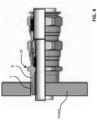
- FIGS. 4 , 5 , and 6 the threaded fitting 10 is shown performing various functions associated with providing hazard protection, e.g., gas, vapor, flame, dust, and water protection, for thin- and thick-walled, enclosures.
- Fig. 4 depicts a partially broken-away sectional view of the threaded fitting affixed to a thick-walled enclosure THWE.
- the threaded fitting 10 is secured to the enclosure as the tapered male threads T of the fitting 10 engage the straight female threads of the thick-walled enclosure THWE.
- the root diameter of the male threads T engage the crests of the straight female threads.
- the tapered male threads As torque is applied to the tapered male threads, a labyrinth seal is produced for mitigating the passage of dust and gas across the interface.
- the male accessory could be a cable gland, a conduit hub or any structure configured for connecting or terminating to the enclosure.
- the tapered threads prevent the flame-path from escaping the enclosure, i.e., functioning as a source of ignition outside the enclosure or into the next zone.
- UL1203 defines the minimum thread engagement necessary for preventing the flame-path from entering other hazardous areas.
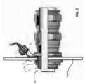
- Fig. 5 depicts a partially broken-away sectional view of the threaded fitting 10 affixed to a thin-walled enclosure TNWE.
- the threaded fitting 10 is secured to the thin-walled enclosure as a locknut LN passes over the first plurality of threads T to engage the second plurality of parallel threads S of the fitting 10.
- a shoulder or flange FL of the fitting 10 is drawn toward the locknut thereby capturing a rim of the aperture therebetween.
- a gasket may be disposed between the flange FL and the thin wall of the enclosure. As such, a water-tight seal can be effected with the aid of a rubber O-ring or gasket.
- the locknut LN passes over the first plurality of tapered threads T to engage the second plurality of parallel threads.
- the male accessory could be a cable gland, a conduit hub or any structure configured for connecting or terminating to the enclosure.
- a locknut has been described in this embodiment, however in other embodiments other types of threaded fasteners may be used in place of a lock nut, such as a Myers Nut.
- Fig. 6 depicts a partially broken-away sectional view of the threaded fitting 10 affixed to thick-walled enclosure THWE, however, in this application, the first plurality of tapered threads extend past the aperture such that the second plurality of parallel threads engage pre-formed threads in the aperture.
- a gasket may be disposed between the flange FL and the thick wall of the enclosure.
- This application is not explosion proof, but is, rather is "weather-proof," i.e., preventing fluids from ingress into the enclosure.
- the male accessory may include a cable gland, conduit hub or other structure for terminating to the enclosure.
- the threaded fitting 10 of the present disclosure may be used in both applications common to explosion-proof fittings 10, i.e., to secure/protect thin- and thick-walled enclosures.
- the quantity of stored inventory can be significantly reduced inasmuch as a single threaded fitting satisfies two requirements.
- the threaded fitting 10 provides a standardized installation which eliminates the need for a separate female threaded adaptor. This further reduces inventory requirements while facilitating ease of assembly.
- the threaded fitting reduces the overall length of installation and, with it, the propensity for impact damage.
- Additional embodiments include any one of the embodiments described above, where one or more of its components, functionalities or structures is interchanged with, replaced by or augmented by one or more of the components, functionalities or structures of a different embodiment described above.
Landscapes
- Engineering & Computer Science (AREA)
- General Engineering & Computer Science (AREA)
- Mechanical Engineering (AREA)
- Architecture (AREA)
- Civil Engineering (AREA)
- Structural Engineering (AREA)
- Gasket Seals (AREA)
- Connection Of Plates (AREA)
Claims (12)
- Raccord fileté (10), comprenant :une première pluralité de filetages (T) conçus pour fournir un joint de type labyrinthe minimisant la migration d'au moins des poussières ou des gaz dangereux ;une seconde pluralité de filetages (S) conçus pour fournir un joint de type labyrinthe pour atténuer les vibrations tout en minimisant la migration d'au moins des fluides ; etun filetage transitoire (TT) entre la première pluralité de filetages et la seconde pluralité de filetages,dans lequel la première et la seconde pluralité de filetages sont disposées en série et peuvent être utilisées pour des enceintes à parois minces ou épaisses pour retarder le passage des gaz et/ou des fluides et/ou des poussières et/ou des flammes,dans lequel chaque filetage de la première pluralité de filetages présente un diamètre de fond (D1), lequel se rétrécit à partir du filetage transitoire vers un plan de référence zéro, et un diamètre de sommet (D3), lequel forme un angle droit ou est parallèle à un axe longitudinal (10A) du raccord fileté,dans lequel la seconde pluralité de filetages présentent un diamètre de fond (D4), lequel est droit ou parallèle à l'axe longitudinal (10A) du raccord fileté.
- Raccord fileté selon la revendication 1, dans lequel chaque filetage de la seconde pluralité de filetages présente en outre un diamètre de sommet (D6), lequel forme un angle droit ou est parallèle à l'axe longitudinal.
- Raccord fileté selon la revendication 1, dans lequel chaque filetage de la seconde pluralité de filetages comprend un diamètre de sommet (D6) qui est égal au diamètre de sommet (D3) de la première pluralité de filetages.
- Raccord fileté selon la revendication 1, dans lequel le filetage transitoire présente un diamètre de sommet (D3) égal à un diamètre de sommet (D6) de la seconde pluralité de filetages et un diamètre de fond (D5), lequel est égal au diamètre de fond (D4) de la seconde pluralité de filetages.
- Raccord fileté selon la revendication 1, dans lequel la première pluralité de filetages comprend entre quatre et six filetages.
- Raccord fileté selon la revendication 1, dans lequel la conicité du diamètre de fond de la première pluralité de filetages varie entre environ un degré (1°) et environ deux degrés un quart (

- Raccord fileté selon la revendication 5, dans lequel la conicité du diamètre de fond de la première pluralité de filetages est comprise entre environ un et trois quarts (1 12/16e) de degré et environ un et treize seizièmes de degré (1 13/16e).
- Raccord fileté selon la revendication 1, dans lequel la seconde pluralité de filetages comprend entre quatre et six filetages.
- Raccord fileté selon la revendication 1, dans lequel la première pluralité de filetages sont conçus pour venir en prise avec les filetages formés dans l'ouverture d'une enceinte à paroi épaisse pour fournir un joint anti-explosion.
- Raccord fileté selon la revendication 1, dans lequel la seconde pluralité de filetages sont conçus pour venir en prise avec un contre-écrou pour fixer le raccord fileté à une enceinte à paroi mince.
- Raccord fileté selon la revendication 1, dans lequel la seconde pluralité de filetages sont conçus pour venir en prise avec les filetages formés dans l'ouverture d'une enceinte à paroi épaisse pour fournir un joint étanche aux intempéries.
- Procédé de fabrication d'un raccord fileté hybride selon la revendication 1, le procédé comprenant :le formage d'une première pluralité de filetages coniques le long d'une ébauche longitudinale, l'ébauche longitudinale s'étendant le long d'un axe longitudinal ;le formage d'un filetage transitoire le long de l'ébauche longitudinale et, en série avec une dernière dent de la première pluralité de filetages ; etle formage d'une seconde pluralité de filetages le long de l'ébauche longitudinale, en série avec le filetage transitoire,dans lequel la seconde pluralité de filetages sont parallèles à l'axe longitudinal,dans lequel chaque filetage de la première pluralité de filetages comprend un diamètre de fond qui se rétrécit à partir du filetage transitoire vers un plan de référence zéro, et un diamètre de sommet qui forme un angle droit ou est parallèle à un axe longitudinal du raccord de filetage.
Applications Claiming Priority (2)
| Application Number | Priority Date | Filing Date | Title |
|---|---|---|---|
| US201962881742P | 2019-08-01 | 2019-08-01 | |
| PCT/EP2020/025353 WO2021018415A1 (fr) | 2019-08-01 | 2020-07-31 | Géométrie de filetage hybride pour raccord fileté |
Publications (2)
| Publication Number | Publication Date |
|---|---|
| EP4007865A1 EP4007865A1 (fr) | 2022-06-08 |
| EP4007865B1 true EP4007865B1 (fr) | 2024-11-27 |
Family
ID=72088041
Family Applications (1)
| Application Number | Title | Priority Date | Filing Date |
|---|---|---|---|
| EP20757217.3A Active EP4007865B1 (fr) | 2019-08-01 | 2020-07-31 | Géométrie de filetage hybride pour raccord fileté |
Country Status (7)
| Country | Link |
|---|---|
| US (1) | US11661966B2 (fr) |
| EP (1) | EP4007865B1 (fr) |
| KR (1) | KR102850527B1 (fr) |
| CN (1) | CN114207303B (fr) |
| CA (1) | CA3145866A1 (fr) |
| MX (1) | MX2022001124A (fr) |
| WO (1) | WO2021018415A1 (fr) |
Families Citing this family (8)
| Publication number | Priority date | Publication date | Assignee | Title |
|---|---|---|---|---|
| CA2984826A1 (fr) * | 2017-11-07 | 2019-05-07 | Complete Group Technologies Ltd. | Raccord filete a multiple amincissement |
| AR113535A1 (es) * | 2017-12-05 | 2020-05-13 | Nippon Steel & Sumitomo Metal Corp | Unión roscada para tubos de acero |
| US20220213971A1 (en) * | 2021-01-04 | 2022-07-07 | Heng-Yi Hsu | Breather plug for installation on liquid storage tanks |
| EP4215716B1 (fr) * | 2022-01-19 | 2024-07-31 | Tenaris Connections B.V. | Raccord de tuyau fileté |
| US20250155055A1 (en) * | 2022-01-20 | 2025-05-15 | Metal One Corporation | Steel pipe joint structure and method for processing steel pipe |
| US12018776B1 (en) * | 2022-01-20 | 2024-06-25 | Tejas Tubular Products, Inc. | Threaded connection |
| TR2022003067A2 (tr) * | 2022-03-02 | 2022-03-21 | Norm Civata San Ve Tic A S | Eksen kaçikliğindan kaynakli montaj problemleri̇ni̇ önleyen bağlanti elemani |
| US11898666B1 (en) * | 2022-08-05 | 2024-02-13 | Saudi Arabian Oil Company | High torque threaded connections with triple taper thread profiles |
Citations (1)
| Publication number | Priority date | Publication date | Assignee | Title |
|---|---|---|---|---|
| EP0669110B1 (fr) * | 1994-02-14 | 2000-05-03 | Smith & Nephew, Inc. | Vis d'interférence avec âme conique double |
Family Cites Families (34)
| Publication number | Priority date | Publication date | Assignee | Title |
|---|---|---|---|---|
| US2355403A (en) * | 1942-10-28 | 1944-08-08 | Tripp William Anthony | Terminator |
| US3248747A (en) * | 1962-11-01 | 1966-05-03 | Nuckey Scott & Company Ltd | Fluteless taps |
| US3352190A (en) * | 1966-02-07 | 1967-11-14 | Textron Ind Inc | Fastener having extruded driving head |
| US3994516A (en) * | 1975-03-05 | 1976-11-30 | Otis Engineering Corporation | Telescoping pipe coupling with improved pressure seal connection threads |
| EP0086852B1 (fr) * | 1982-02-18 | 1986-08-27 | Conti Fasteners AG | Vis |
| CN1020562C (zh) * | 1987-07-01 | 1993-05-12 | 川崎重工业株式会社 | 异种材料的复合体及其制造方法 |
| EP0845607B1 (fr) * | 1996-11-29 | 2002-03-27 | Max Co., Ltd. | Vis auto-taraudeuse. |
| JP3336257B2 (ja) * | 1998-07-07 | 2002-10-21 | 株式会社青山製作所 | ボルト |
| US6149363A (en) * | 1998-10-29 | 2000-11-21 | Huck International, Inc. | Lightweight threaded fastener and thread rolling die |
| US6089806A (en) * | 1999-01-25 | 2000-07-18 | Conti Fasteners | Blank for self-tapping fastener |
| DE19948515A1 (de) | 1999-10-08 | 2001-04-12 | Bielomatik Leuze & Co | Fügeeinheit für Haftnähte, insbesondere Vibrationsschweißungen |
| US6659878B2 (en) * | 2001-03-30 | 2003-12-09 | General Electric Company | Method and apparatus for coupling male threads to female threads |
| DE10235817B4 (de) * | 2002-08-05 | 2004-08-05 | Ejot Gmbh & Co. Kg | Selbstfurchende Schraube |
| US7934895B2 (en) * | 2003-10-10 | 2011-05-03 | Illinois Tool Works Inc. | Self-drilling anchor |
| MX2008013790A (es) * | 2006-04-27 | 2009-01-09 | Ina Acquisition Corp | Reposicion de una conexión de salida en un conducto revestido. |
| DE102006000232A1 (de) * | 2006-05-16 | 2007-11-22 | Hilti Ag | Spanlos gewindeformende Schraube |
| DE102007000154B4 (de) * | 2007-03-15 | 2023-12-07 | Hilti Aktiengesellschaft | Spanlos gewindeformende Schraube |
| FR2917805B1 (fr) | 2007-06-25 | 2009-09-04 | Vallourec Mannesmann Oil & Gas | Element filete de composant a filetage antagonistes, et joint filete tubulaire correspondant |
| JP4701253B2 (ja) * | 2008-01-21 | 2011-06-15 | 新一 西田 | ボルト及びそれを用いた締結具 |
| JP4787295B2 (ja) * | 2008-07-14 | 2011-10-05 | 株式会社トープラ | 高強度セルフフォーミングねじによるねじ締結構造体 |
| FR2939861B1 (fr) | 2008-12-16 | 2010-12-24 | Vallourec Mannesmann Oil & Gas France | Joint tubulaire a filetage autobloquant utilise dans l'industrie du petrole |
| FR2940677B1 (fr) | 2008-12-29 | 2016-07-22 | Vallourec Mannesmann Oil & Gas France | Joint tubulaire etanche utilise dans l'industrie du petrole |
| JP2010185568A (ja) * | 2009-01-14 | 2010-08-26 | Smc Corp | 管継手 |
| US9297481B2 (en) * | 2009-02-20 | 2016-03-29 | Swagelok Company | Conduit fitting with torque collar |
| US8282676B2 (en) * | 2009-05-28 | 2012-10-09 | Griffin T Hall | Tapered thread root transition on cortical bone fastener |
| US20110042935A1 (en) | 2009-08-24 | 2011-02-24 | Belinda Bain | Conduit/Piping Sump Penetration Fitting |
| DE102009048160B4 (de) | 2009-10-02 | 2019-05-16 | Böllhoff Verbindungstechnik GmbH | Einformbare Drahtgewindeeinsätze, Bauteil mit einformbarem Drahtgewindeeinsatz sowie Herstellungsverfahren eines Bauteils mit einformbarem Drahtgewindeeinsatz |
| JP5168597B2 (ja) * | 2010-02-12 | 2013-03-21 | 住友電工ハードメタル株式会社 | ヘッド着脱式切削工具 |
| US8931809B2 (en) | 2012-09-21 | 2015-01-13 | Vallourec Oil And Gas France | Tubular threaded connection |
| FR3010156B1 (fr) * | 2013-08-30 | 2016-02-26 | Faurecia Interieur Ind | Element de fixation filete |
| US9683684B1 (en) * | 2015-12-09 | 2017-06-20 | Certus Energy Solutions, Llc | Tubular coupling |
| AU2016394560B2 (en) | 2016-02-23 | 2019-10-03 | Nippon Steel Corporation | Threaded joint for steel pipes |
| CN109424314B (zh) * | 2017-08-25 | 2021-01-05 | 中国石油化工股份有限公司 | 一种水平井用液动冲击器 |
| CA2984826A1 (fr) * | 2017-11-07 | 2019-05-07 | Complete Group Technologies Ltd. | Raccord filete a multiple amincissement |
-
2020
- 2020-07-31 EP EP20757217.3A patent/EP4007865B1/fr active Active
- 2020-07-31 KR KR1020227006296A patent/KR102850527B1/ko active Active
- 2020-07-31 WO PCT/EP2020/025353 patent/WO2021018415A1/fr not_active Ceased
- 2020-07-31 CN CN202080055373.2A patent/CN114207303B/zh active Active
- 2020-07-31 CA CA3145866A patent/CA3145866A1/fr active Pending
- 2020-07-31 MX MX2022001124A patent/MX2022001124A/es unknown
- 2020-07-31 US US16/944,310 patent/US11661966B2/en active Active
Patent Citations (1)
| Publication number | Priority date | Publication date | Assignee | Title |
|---|---|---|---|---|
| EP0669110B1 (fr) * | 1994-02-14 | 2000-05-03 | Smith & Nephew, Inc. | Vis d'interférence avec âme conique double |
Also Published As
| Publication number | Publication date |
|---|---|
| CN114207303B (zh) | 2023-11-21 |
| US20210033136A1 (en) | 2021-02-04 |
| KR20220041869A (ko) | 2022-04-01 |
| CA3145866A1 (fr) | 2021-02-04 |
| EP4007865A1 (fr) | 2022-06-08 |
| KR102850527B1 (ko) | 2025-08-25 |
| MX2022001124A (es) | 2022-02-16 |
| CN114207303A (zh) | 2022-03-18 |
| US11661966B2 (en) | 2023-05-30 |
| WO2021018415A1 (fr) | 2021-02-04 |
Similar Documents
| Publication | Publication Date | Title |
|---|---|---|
| EP4007865B1 (fr) | Géométrie de filetage hybride pour raccord fileté | |
| CN1230960C (zh) | 连接配件和连接方法 | |
| US4877271A (en) | Hydraulic connector | |
| US11322919B2 (en) | Cable entry device for electrical cable housed in a conduit | |
| US5711549A (en) | High pressure quick connect for use in automotive brake system application | |
| JPH0485A (ja) | 管継手 | |
| CA2893196A1 (fr) | Recepteurs de conduit | |
| US20190093807A1 (en) | Fitting Device, Arrangement and Method | |
| US11451027B2 (en) | Press coupler for electrical conduit | |
| US20190013656A1 (en) | Angularly Adjustable Tubular Elbow | |
| US5230536A (en) | Bulkhead mounting assembly | |
| CN1193184C (zh) | 防止松脱的固定连接组件和方法 | |
| US20180224032A1 (en) | Termination for Sheathed Tubing with Leak Containment and Detection Provisions | |
| US4432571A (en) | Retainer gland for mechanical joint pipe | |
| US5290071A (en) | Coaxial conduit bulkhead mounting assembly | |
| US10302230B2 (en) | Field serviceable conduit receivers | |
| US11996683B2 (en) | Compressible condulet devices, assemblies, systems and methods for electrical raceway fabrication | |
| US20220128180A1 (en) | Transition Adapter | |
| EP0565289A1 (fr) | Accouplement | |
| EP3833899A1 (fr) | Dispositifs et ensembles de couplage hydraulique améliorés | |
| US12015256B2 (en) | Push-in condulet devices, assemblies, systems and methods for electrical raceway fabrication | |
| EP3736478B1 (fr) | Ensemble soupape | |
| CA3250271A1 (fr) | Traversée à arrêt deux-pièces | |
| EP0465702A1 (fr) | Dispositif et procédé pour la réparation d'une voie d'écoulement équipée pour traverser des chambres de pompes à haute pression d'installations nucléaires ou dispositifs similaires |
Legal Events
| Date | Code | Title | Description |
|---|---|---|---|
| STAA | Information on the status of an ep patent application or granted ep patent |
Free format text: STATUS: UNKNOWN |
|
| STAA | Information on the status of an ep patent application or granted ep patent |
Free format text: STATUS: THE INTERNATIONAL PUBLICATION HAS BEEN MADE |
|
| PUAI | Public reference made under article 153(3) epc to a published international application that has entered the european phase |
Free format text: ORIGINAL CODE: 0009012 |
|
| STAA | Information on the status of an ep patent application or granted ep patent |
Free format text: STATUS: REQUEST FOR EXAMINATION WAS MADE |
|
| 17P | Request for examination filed |
Effective date: 20220210 |
|
| AK | Designated contracting states |
Kind code of ref document: A1 Designated state(s): AL AT BE BG CH CY CZ DE DK EE ES FI FR GB GR HR HU IE IS IT LI LT LU LV MC MK MT NL NO PL PT RO RS SE SI SK SM TR |
|
| DAV | Request for validation of the european patent (deleted) | ||
| DAX | Request for extension of the european patent (deleted) | ||
| P01 | Opt-out of the competence of the unified patent court (upc) registered |
Effective date: 20230521 |
|
| STAA | Information on the status of an ep patent application or granted ep patent |
Free format text: STATUS: EXAMINATION IS IN PROGRESS |
|
| 17Q | First examination report despatched |
Effective date: 20231215 |
|
| REG | Reference to a national code |
Ref country code: DE Ref legal event code: R079 Ref document number: 602020042074 Country of ref document: DE Free format text: PREVIOUS MAIN CLASS: F16L0005040000 Ipc: F16L0005060000 |
|
| GRAP | Despatch of communication of intention to grant a patent |
Free format text: ORIGINAL CODE: EPIDOSNIGR1 |
|
| STAA | Information on the status of an ep patent application or granted ep patent |
Free format text: STATUS: GRANT OF PATENT IS INTENDED |
|
| RIC1 | Information provided on ipc code assigned before grant |
Ipc: H02G 3/06 20060101ALI20240628BHEP Ipc: F16B 33/02 20060101ALI20240628BHEP Ipc: F16B 33/00 20060101ALI20240628BHEP Ipc: F16L 41/14 20060101ALI20240628BHEP Ipc: F16L 5/06 20060101AFI20240628BHEP |
|
| INTG | Intention to grant announced |
Effective date: 20240718 |
|
| GRAS | Grant fee paid |
Free format text: ORIGINAL CODE: EPIDOSNIGR3 |
|
| GRAA | (expected) grant |
Free format text: ORIGINAL CODE: 0009210 |
|
| STAA | Information on the status of an ep patent application or granted ep patent |
Free format text: STATUS: THE PATENT HAS BEEN GRANTED |
|
| AK | Designated contracting states |
Kind code of ref document: B1 Designated state(s): AL AT BE BG CH CY CZ DE DK EE ES FI FR GB GR HR HU IE IS IT LI LT LU LV MC MK MT NL NO PL PT RO RS SE SI SK SM TR |
|
| REG | Reference to a national code |
Ref country code: GB Ref legal event code: FG4D |
|
| REG | Reference to a national code |
Ref country code: CH Ref legal event code: EP |
|
| REG | Reference to a national code |
Ref country code: DE Ref legal event code: R096 Ref document number: 602020042074 Country of ref document: DE |
|
| REG | Reference to a national code |
Ref country code: IE Ref legal event code: FG4D |
|
| REG | Reference to a national code |
Ref country code: LT Ref legal event code: MG9D |
|
| REG | Reference to a national code |
Ref country code: NL Ref legal event code: MP Effective date: 20241127 |
|
| PG25 | Lapsed in a contracting state [announced via postgrant information from national office to epo] |
Ref country code: HR Free format text: LAPSE BECAUSE OF FAILURE TO SUBMIT A TRANSLATION OF THE DESCRIPTION OR TO PAY THE FEE WITHIN THE PRESCRIBED TIME-LIMIT Effective date: 20241127 Ref country code: IS Free format text: LAPSE BECAUSE OF FAILURE TO SUBMIT A TRANSLATION OF THE DESCRIPTION OR TO PAY THE FEE WITHIN THE PRESCRIBED TIME-LIMIT Effective date: 20250327 Ref country code: PT Free format text: LAPSE BECAUSE OF FAILURE TO SUBMIT A TRANSLATION OF THE DESCRIPTION OR TO PAY THE FEE WITHIN THE PRESCRIBED TIME-LIMIT Effective date: 20250327 |
|
| PG25 | Lapsed in a contracting state [announced via postgrant information from national office to epo] |
Ref country code: NL Free format text: LAPSE BECAUSE OF FAILURE TO SUBMIT A TRANSLATION OF THE DESCRIPTION OR TO PAY THE FEE WITHIN THE PRESCRIBED TIME-LIMIT Effective date: 20241127 Ref country code: FI Free format text: LAPSE BECAUSE OF FAILURE TO SUBMIT A TRANSLATION OF THE DESCRIPTION OR TO PAY THE FEE WITHIN THE PRESCRIBED TIME-LIMIT Effective date: 20241127 |
|
| REG | Reference to a national code |
Ref country code: AT Ref legal event code: MK05 Ref document number: 1746009 Country of ref document: AT Kind code of ref document: T Effective date: 20241127 |
|
| PG25 | Lapsed in a contracting state [announced via postgrant information from national office to epo] |
Ref country code: BG Free format text: LAPSE BECAUSE OF FAILURE TO SUBMIT A TRANSLATION OF THE DESCRIPTION OR TO PAY THE FEE WITHIN THE PRESCRIBED TIME-LIMIT Effective date: 20241127 |
|
| PG25 | Lapsed in a contracting state [announced via postgrant information from national office to epo] |
Ref country code: ES Free format text: LAPSE BECAUSE OF FAILURE TO SUBMIT A TRANSLATION OF THE DESCRIPTION OR TO PAY THE FEE WITHIN THE PRESCRIBED TIME-LIMIT Effective date: 20241127 |
|
| PG25 | Lapsed in a contracting state [announced via postgrant information from national office to epo] |
Ref country code: NO Free format text: LAPSE BECAUSE OF FAILURE TO SUBMIT A TRANSLATION OF THE DESCRIPTION OR TO PAY THE FEE WITHIN THE PRESCRIBED TIME-LIMIT Effective date: 20250227 |
|
| PG25 | Lapsed in a contracting state [announced via postgrant information from national office to epo] |
Ref country code: LV Free format text: LAPSE BECAUSE OF FAILURE TO SUBMIT A TRANSLATION OF THE DESCRIPTION OR TO PAY THE FEE WITHIN THE PRESCRIBED TIME-LIMIT Effective date: 20241127 Ref country code: GR Free format text: LAPSE BECAUSE OF FAILURE TO SUBMIT A TRANSLATION OF THE DESCRIPTION OR TO PAY THE FEE WITHIN THE PRESCRIBED TIME-LIMIT Effective date: 20250228 Ref country code: AT Free format text: LAPSE BECAUSE OF FAILURE TO SUBMIT A TRANSLATION OF THE DESCRIPTION OR TO PAY THE FEE WITHIN THE PRESCRIBED TIME-LIMIT Effective date: 20241127 |
|
| PG25 | Lapsed in a contracting state [announced via postgrant information from national office to epo] |
Ref country code: PL Free format text: LAPSE BECAUSE OF FAILURE TO SUBMIT A TRANSLATION OF THE DESCRIPTION OR TO PAY THE FEE WITHIN THE PRESCRIBED TIME-LIMIT Effective date: 20241127 |
|
| PG25 | Lapsed in a contracting state [announced via postgrant information from national office to epo] |
Ref country code: RS Free format text: LAPSE BECAUSE OF FAILURE TO SUBMIT A TRANSLATION OF THE DESCRIPTION OR TO PAY THE FEE WITHIN THE PRESCRIBED TIME-LIMIT Effective date: 20250227 |
|
| PG25 | Lapsed in a contracting state [announced via postgrant information from national office to epo] |
Ref country code: SM Free format text: LAPSE BECAUSE OF FAILURE TO SUBMIT A TRANSLATION OF THE DESCRIPTION OR TO PAY THE FEE WITHIN THE PRESCRIBED TIME-LIMIT Effective date: 20241127 |
|
| PG25 | Lapsed in a contracting state [announced via postgrant information from national office to epo] |
Ref country code: DK Free format text: LAPSE BECAUSE OF FAILURE TO SUBMIT A TRANSLATION OF THE DESCRIPTION OR TO PAY THE FEE WITHIN THE PRESCRIBED TIME-LIMIT Effective date: 20241127 |
|
| PGFP | Annual fee paid to national office [announced via postgrant information from national office to epo] |
Ref country code: GB Payment date: 20250619 Year of fee payment: 6 |
|
| PG25 | Lapsed in a contracting state [announced via postgrant information from national office to epo] |
Ref country code: EE Free format text: LAPSE BECAUSE OF FAILURE TO SUBMIT A TRANSLATION OF THE DESCRIPTION OR TO PAY THE FEE WITHIN THE PRESCRIBED TIME-LIMIT Effective date: 20241127 |
|
| PGFP | Annual fee paid to national office [announced via postgrant information from national office to epo] |
Ref country code: FR Payment date: 20250620 Year of fee payment: 6 |
|
| PG25 | Lapsed in a contracting state [announced via postgrant information from national office to epo] |
Ref country code: RO Free format text: LAPSE BECAUSE OF FAILURE TO SUBMIT A TRANSLATION OF THE DESCRIPTION OR TO PAY THE FEE WITHIN THE PRESCRIBED TIME-LIMIT Effective date: 20241127 |
|
| PG25 | Lapsed in a contracting state [announced via postgrant information from national office to epo] |
Ref country code: SK Free format text: LAPSE BECAUSE OF FAILURE TO SUBMIT A TRANSLATION OF THE DESCRIPTION OR TO PAY THE FEE WITHIN THE PRESCRIBED TIME-LIMIT Effective date: 20241127 |
|
| PG25 | Lapsed in a contracting state [announced via postgrant information from national office to epo] |
Ref country code: CZ Free format text: LAPSE BECAUSE OF FAILURE TO SUBMIT A TRANSLATION OF THE DESCRIPTION OR TO PAY THE FEE WITHIN THE PRESCRIBED TIME-LIMIT Effective date: 20241127 |
|
| PG25 | Lapsed in a contracting state [announced via postgrant information from national office to epo] |
Ref country code: IT Free format text: LAPSE BECAUSE OF FAILURE TO SUBMIT A TRANSLATION OF THE DESCRIPTION OR TO PAY THE FEE WITHIN THE PRESCRIBED TIME-LIMIT Effective date: 20241127 |
|
| REG | Reference to a national code |
Ref country code: DE Ref legal event code: R097 Ref document number: 602020042074 Country of ref document: DE |
|
| PG25 | Lapsed in a contracting state [announced via postgrant information from national office to epo] |
Ref country code: SE Free format text: LAPSE BECAUSE OF FAILURE TO SUBMIT A TRANSLATION OF THE DESCRIPTION OR TO PAY THE FEE WITHIN THE PRESCRIBED TIME-LIMIT Effective date: 20241127 |
|
| PLBE | No opposition filed within time limit |
Free format text: ORIGINAL CODE: 0009261 |
|
| STAA | Information on the status of an ep patent application or granted ep patent |
Free format text: STATUS: NO OPPOSITION FILED WITHIN TIME LIMIT |
|
| REG | Reference to a national code |
Ref country code: CH Ref legal event code: L10 Free format text: ST27 STATUS EVENT CODE: U-0-0-L10-L00 (AS PROVIDED BY THE NATIONAL OFFICE) Effective date: 20251008 |
|
| PGFP | Annual fee paid to national office [announced via postgrant information from national office to epo] |
Ref country code: DE Payment date: 20250620 Year of fee payment: 6 |
|
| 26N | No opposition filed |
Effective date: 20250828 |
|
| REG | Reference to a national code |
Ref country code: CH Ref legal event code: H13 Free format text: ST27 STATUS EVENT CODE: U-0-0-H10-H13 (AS PROVIDED BY THE NATIONAL OFFICE) Effective date: 20260224 |
|
| PG25 | Lapsed in a contracting state [announced via postgrant information from national office to epo] |
Ref country code: LU Free format text: LAPSE BECAUSE OF NON-PAYMENT OF DUE FEES Effective date: 20250731 |
|
| REG | Reference to a national code |
Ref country code: BE Ref legal event code: MM Effective date: 20250731 |
|
| PG25 | Lapsed in a contracting state [announced via postgrant information from national office to epo] |
Ref country code: BE Free format text: LAPSE BECAUSE OF NON-PAYMENT OF DUE FEES Effective date: 20250731 |
|
| PG25 | Lapsed in a contracting state [announced via postgrant information from national office to epo] |
Ref country code: CH Free format text: LAPSE BECAUSE OF NON-PAYMENT OF DUE FEES Effective date: 20250731 |