EP4007870B1 - Vertikale haube - Google Patents
Vertikale haube Download PDFInfo
- Publication number
- EP4007870B1 EP4007870B1 EP20754372.9A EP20754372A EP4007870B1 EP 4007870 B1 EP4007870 B1 EP 4007870B1 EP 20754372 A EP20754372 A EP 20754372A EP 4007870 B1 EP4007870 B1 EP 4007870B1
- Authority
- EP
- European Patent Office
- Prior art keywords
- panel
- pin
- section
- box
- housing
- Prior art date
- Legal status (The legal status is an assumption and is not a legal conclusion. Google has not performed a legal analysis and makes no representation as to the accuracy of the status listed.)
- Active
Links
Images


Classifications
-
- E—FIXED CONSTRUCTIONS
- E05—LOCKS; KEYS; WINDOW OR DOOR FITTINGS; SAFES
- E05D—HINGES OR SUSPENSION DEVICES FOR DOORS, WINDOWS OR WINGS
- E05D7/00—Hinges or pivots of special construction
- E05D7/10—Hinges or pivots of special construction to allow easy separation or connection of the parts at the hinge axis
-
- E—FIXED CONSTRUCTIONS
- E05—LOCKS; KEYS; WINDOW OR DOOR FITTINGS; SAFES
- E05D—HINGES OR SUSPENSION DEVICES FOR DOORS, WINDOWS OR WINGS
- E05D11/00—Additional features or accessories of hinges
- E05D11/10—Devices for preventing movement between relatively-movable hinge parts
- E05D11/1014—Devices for preventing movement between relatively-movable hinge parts for maintaining the hinge in only one position, e.g. closed
-
- E—FIXED CONSTRUCTIONS
- E05—LOCKS; KEYS; WINDOW OR DOOR FITTINGS; SAFES
- E05D—HINGES OR SUSPENSION DEVICES FOR DOORS, WINDOWS OR WINGS
- E05D3/00—Hinges with pins
- E05D3/02—Hinges with pins with one pin
- E05D3/022—Hinges with pins with one pin allowing an additional lateral movement, e.g. for sealing
-
- E—FIXED CONSTRUCTIONS
- E05—LOCKS; KEYS; WINDOW OR DOOR FITTINGS; SAFES
- E05D—HINGES OR SUSPENSION DEVICES FOR DOORS, WINDOWS OR WINGS
- E05D5/00—Construction of single parts, e.g. the parts for attachment
- E05D5/02—Parts for attachment, e.g. flaps
-
- E—FIXED CONSTRUCTIONS
- E05—LOCKS; KEYS; WINDOW OR DOOR FITTINGS; SAFES
- E05D—HINGES OR SUSPENSION DEVICES FOR DOORS, WINDOWS OR WINGS
- E05D5/00—Construction of single parts, e.g. the parts for attachment
- E05D5/10—Pins, sockets or sleeves; Removable pins
-
- E—FIXED CONSTRUCTIONS
- E05—LOCKS; KEYS; WINDOW OR DOOR FITTINGS; SAFES
- E05D—HINGES OR SUSPENSION DEVICES FOR DOORS, WINDOWS OR WINGS
- E05D5/00—Construction of single parts, e.g. the parts for attachment
- E05D5/10—Pins, sockets or sleeves; Removable pins
- E05D5/12—Securing pins in sockets, movably or not
-
- E—FIXED CONSTRUCTIONS
- E05—LOCKS; KEYS; WINDOW OR DOOR FITTINGS; SAFES
- E05D—HINGES OR SUSPENSION DEVICES FOR DOORS, WINDOWS OR WINGS
- E05D7/00—Hinges or pivots of special construction
- E05D7/12—Hinges or pivots of special construction to allow easy detachment of the hinge from the wing or the frame
-
- F—MECHANICAL ENGINEERING; LIGHTING; HEATING; WEAPONS; BLASTING
- F24—HEATING; RANGES; VENTILATING
- F24C—DOMESTIC STOVES OR RANGES ; DETAILS OF DOMESTIC STOVES OR RANGES, OF GENERAL APPLICATION
- F24C15/00—Details
- F24C15/20—Removing cooking fumes
-
- F—MECHANICAL ENGINEERING; LIGHTING; HEATING; WEAPONS; BLASTING
- F24—HEATING; RANGES; VENTILATING
- F24C—DOMESTIC STOVES OR RANGES ; DETAILS OF DOMESTIC STOVES OR RANGES, OF GENERAL APPLICATION
- F24C15/00—Details
- F24C15/20—Removing cooking fumes
- F24C15/2078—Removing cooking fumes movable
- F24C15/2092—Removing cooking fumes movable extendable or pivotable
-
- E—FIXED CONSTRUCTIONS
- E05—LOCKS; KEYS; WINDOW OR DOOR FITTINGS; SAFES
- E05D—HINGES OR SUSPENSION DEVICES FOR DOORS, WINDOWS OR WINGS
- E05D5/00—Construction of single parts, e.g. the parts for attachment
- E05D5/10—Pins, sockets or sleeves; Removable pins
- E05D2005/102—Pins
- E05D2005/106—Pins with non-cylindrical portions
Definitions
- US 6 622 345 B2 discloses a box-like housing of a household appliance having one openable side.
- the document discloses a hinge mechanism located at one side that allows rotation of the door associated with that side.
- an engagement portion connected to the door, engages with the box-like housing, allowing the door to be locked in the open position.
- the technical purpose of the present invention is to provide a hood for extracting cooking fumes that can obviate the above mentioned prior art drawbacks.
- the object of the present invention is to provide a hood for extracting cooking fumes that affords quicker installation.
- a further object of the present invention is to simplify the panel moving mechanism and facilitate panel removal from the box-like housing.
- a further object of the present invention is to reduce the hood manufacturing costs.
- the hood obviates the technical problem as it comprises a hinge comprising a stationary element and a movable element.
- the movable element is attached to the panel, whereas the stationary element is joined to the box-like housing.
- the movable element is configured to rotate relative to the stationary element when the covering panel switches from the closed configuration to the open configuration.
- the movable element is also configured to slide relative to the stationary element, thereby causing the panel to slide relative to the box-like housing. The sliding movement of the panel allows it to be locked or unlocked when it is in the open configuration.
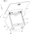
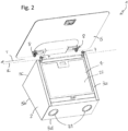
- numeral 1 designates a cooking fume extractor hood of the present invention.
- the box-like housing 2 also has a rear side 3b, directly facing the wall 21 and opposite to the front side 3a.
- the box-like housing 2 also has an upper side 3c, facing the ceiling, and a lower side 3d, facing a hob.
- the lower side 3d comprises lighting means 31.
- the box-like housing 2 has an opening 4 through which cooking fumes are channeled.
- the opening 4 is located on the front side 3a of the box-like housing 2.
- the hood 1 comprises a panel 5 connected to the box-like housing 2 and namely arranged outside it.
- This panel 5 can face the opening 4 to cover it.
- the panel may be translucent or opaque.
- the panel may be made of glass and/or a polymeric material and/or metal.
- the hood 1 comprises at least one hinge 6.
- the hinge 6 is connected to the panel 5 and to the box-like housing 2.
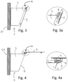
- the hinge 6 is configured to allow the panel 5 to rotate relative to the box-like housing 2, thereby switching the panel between the closed configuration and the open configuration.
- the hinge 6 is arranged at the front side 3a, spaced apart from the upper side 3c.
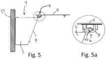
- the hinge 6 comprises a stationary element 7 joined to the box-like housing 2, and a movable element 8 attached to the panel 5.
- the movable element 8 when the panel 5 is in the open configuration, the movable element 8 is configured to slide relative to the stationary element 7 to switch the panel 5 into the locked configuration.
- the movable element 8 and the panel 5 are configured to slide in a direction "S" substantially parallel to the upper side 3b.
- the movable element 8 is configured to slide along a first predetermined length, for example toward the wall 21, to switch the panel 5 from the unlocked configuration to the locked configuration.
- a first predetermined length for example toward the wall 21, to switch the panel 5 from the unlocked configuration to the locked configuration.
- the panel 5 can be switched back to the unlocked configuration by sliding the movable element 8 in the opposite direction, i.e. away from the wall 21, along the same first predetermined length.
- the panel 5 can be switched from the open configuration to the closed configuration.
- the movable element 8 comprises a guide 9.
- the stationary element 7 comprises a pin 10 placed within the guide 9, and a support 11 attached to the box-like housing 2.
- the pin 10 extends away from the support 11 and has one end 12 distal from such support 11.
- the pin 10 also comprises a head 13, placed at the end 12 of the pin 10 and configured to keep the pin 10 within the guide 9.
- the guide 9 is adapted to rotate relative to the pin 10 to switch the panel 5 between the closed configuration and the open configuration. Furthermore, such guide 9 can slide relative to the pin 10 to lock or unlock the rotation of the panel 5 when the panel 5 is in the open configuration.
- the guide 9 is defined by a through groove 15, inside which the body 14 of the pin 10 is arranged.
- the guide 9 has a straight main direction of extension "J". The guide 9 slides relative to the pin 10 in this direction "J".
- the guide 9 comprises a rotating section 16.
- the pin 10 is configured to engage the rotating section 16 to cause the panel 5 to reversibly rotate from the closed configuration to the open configuration, in particular to the unlocked configuration.
- the guide 9 can rotate relative to the pin 10 when the pin 10 engages the rotating section 16. It should be noted that, when the panel 5 rotates, the aforementioned axis of rotation "R" extends through the pin 10.
- the rotating section 16 and the locking section 17 are each positioned on a respective end 19a, 19b of the guide 9.
- the rotating section 16 has a circular shape with a radius equal to the maximum width of the body 14 of the pin 10 to allow the guide 9 to rotate around it.
- the rotating section 16 has a dimension at least equal to the longer side 31.
- the locking section 17 has a shape that matches the shape of the body 14 of the pin 10 to prevent undesired rotation of the guide 9 relative thereto.
- the guide 9 slides along the longer side 31 of the body 14, and the body 14 abuts the locking section 17 with its shorter side 32.
- the locking section 17 has a dimension equal to the shorter side 32 of the body 14 of the pin 10.
- the hood 1 comprises a pair of hinges 6.
- the respective pins 10 of each hinge 6 extend on the same side as their respective support 11, to allow the panel 5 to translate in the direction "T" to disconnect the panel 5.
Landscapes
- Engineering & Computer Science (AREA)
- Mechanical Engineering (AREA)
- Chemical & Material Sciences (AREA)
- Combustion & Propulsion (AREA)
- General Engineering & Computer Science (AREA)
- Ventilation (AREA)
- Casings For Electric Apparatus (AREA)
- Glass Compositions (AREA)
- Seal Device For Vehicle (AREA)
- Outer Garments And Coats (AREA)
Claims (10)
- Haube (1) zum Absaugen von Kochdämpfen, umfassend:- ein kastenartiges Gehäuse (2), das eine Vorderseite (3a) mit einer darin ausgebildeten Öffnung (4) zum Absaugen von Kochdämpfen aufweist;- Saugmittel, die in dem kastenartigen Gehäuse (2) angeordnet sind, um die Kochdämpfe durch die Öffnung (4) zu leiten;- eine Abdeckplatte (5), die außerhalb des kastenartigen Gehäuses (2) platziert und dazu ausgelegt ist, der Öffnung (4) zugewandt zu sein;- mindestens ein Scharnier (6), das mit dem kastenartigen Gehäuse (2) und der Platte (5) verbunden ist, um eine Schwenkbewegung der Platte (5) relativ zu dem kastenartigen Gehäuse (2) zu ermöglichen, wobei die Platte (5) dazu konfiguriert ist, zwischen einer geschlossenen Konfiguration, in der sie angrenzend an die Öffnung (4) platziert ist, und einer offenen Konfiguration, in der das Innere des kastenartigen Gehäuses (2) über die Öffnung (4) zugänglich ist, zu wechseln; wobei das Scharnier (6) ein stationäres Element (7), das mit dem kastenartigen Gehäuse (2) verbunden ist, und ein bewegliches Element (8), das an der Platte (5) befestigt ist, umfasst, wobei das bewegliche Element (8) dazu ausgelegt ist, sich um eine Drehachse ("R") zu drehen, um die Platte (5) von der geschlossenen Konfiguration in die offene Konfiguration zu wechseln;wobei das bewegliche Element (8) dazu konfiguriert ist, relativ zu dem stationären Element (7) zu gleiten, um die Schwenkbewegung der Platte (5) in der offenen Konfiguration zu verriegeln.dadurch gekennzeichnet, dass- das bewegliche Element (8) eine Führung (9) umfasst, die einen Drehabschnitt (16) und einen Verriegelungsabschnitt (17) umfasst, der dem Drehabschnitt (16) gegenüberliegt und von diesem durch die erste vorbestimmte Länge getrennt ist;- das stationäre Element (7) einen Stift (10) umfasst, der innerhalb der Führung (9) platziert ist, wobei die Führung (9) angepasst ist, um relativ zu dem Stift (10) zu schwenken, der mit dem Drehabschnitt (16) in Eingriff steht, um die Platte (5) reversibel von der geschlossenen Konfiguration in die offene Konfiguration zu wechseln, wobei die Führung (9) auch angepasst ist, um relativ zu dem Stift (10) zu gleiten, der sich von dem Drehabschnitt (16) zu dem Verriegelungsabschnitt (17) und umgekehrt bewegt, um die Schwenkbewegung der Platte (5) zu verriegeln oder zu entriegeln, wenn der Stift (10) jeweils in den Verriegelungsabschnitt (17) eingreift oder sich davon löst, wenn sich die Platte (5) in der offenen Konfiguration befindet, wobei das stationäre Element (7) eine an dem kastenartigen Gehäuse (2) angebrachte Stütze (11) umfasst, wobei sich der Stift (10) von der Stütze (11) weg erstreckt und ein Ende (12) distal von der Stütze (11) aufweist, wobei der Stift (10) einen Körper (14) umfasst, wobei der Verriegelungsabschnitt (17) eine Form aufweist, die der Form des Körpers (14) entspricht, um eine unerwünschte Drehung der Führung (9) relativ dazu zu verhindern, wenn der Stift (10) in den Verriegelungsabschnitt (17) eingreift.
- Haube (1) nach dem vorstehenden Anspruch, wobei der Stift (10) einen Kopf (13) an dem Ende (12) umfasst, der dazu konfiguriert ist, den Stift (10) in der Führung (9) zu halten, wobei der Körper (14) zwischen der Stütze (11) und dem Kopf (13) angeordnet ist.
- Haube (1) nach dem vorstehenden Anspruch, wobei die Führung (9) einen Freigabeabschnitt (18) umfasst und der Stift (10) aus der Führung (9) herausgezogen werden kann, um die Platte (5) von dem kastenartigen Gehäuse (2) zu trennen, wenn der Stift (10) in den Freigabeabschnitt (18) eingreift.
- Haube (1) nach Anspruch 2 oder 3, wobei der Drehabschnitt (16) und der Verriegelungsabschnitt (17) jeweils an einem entsprechenden Ende (19a, 19b) der Führung (9) positioniert sind, wobei der Stift (10) dazu konfiguriert ist, mit dem Drehabschnitt (16) in Eingriff zu kommen, um die Platte (5) reversibel von der geschlossenen Konfiguration in die offene Konfiguration zu wechseln, und dazu konfiguriert ist, sich von dem Drehabschnitt (16) zu dem Verriegelungsabschnitt (17) zu bewegen, wenn sich die Platte (5) in der offenen Konfiguration befindet.
- Haube (1) nach dem vorstehenden Anspruch, wobei der Stift (10) dazu konfiguriert ist, sich von dem Drehabschnitt (16) und/oder dem Verriegelungsabschnitt (17) zu dem Freigabeabschnitt (18) zu bewegen, wobei die Platte (5) in der Lage ist, von dem kastenartigen Gehäuse (2) getrennt zu werden, wenn der Stift (10) in den Freigabeabschnitt (18) eingreift.
- Haube (1) nach dem vorstehenden Anspruch, wobei die Platte (5) dazu konfiguriert ist, sich in einer Richtung ("T") parallel zu der Drehachse ("R") zu verschieben, wenn der Stift (10) in den Freigabeabschnitt (18) eingreift, um von dem kastenartigen Gehäuse (2) getrennt werden zu können.
- Haube (1) nach Anspruch 5 oder 6, wobei der Freigabeabschnitt (18) in einer Zwischenposition zwischen dem Verriegelungsabschnitt (17) und dem Drehabschnitt (16) platziert ist.
- Haube (1) nach einem der Ansprüche 5 bis 7, wobei der Freigabeabschnitt (18) eine Form aufweist, die der Form des Kopfes (13) des Stifts (10) entspricht.
- Haube (1) nach einem der vorstehenden Ansprüche, umfassend ein Paar Scharniere (6), deren jeweilige Stifte (10) sich von derselben Seite ihrer jeweiligen Stütze (11) erstrecken, um ein Verschieben der Platte (5) in die Richtung ("T") zu ermöglichen.
- Haube (1) nach einem der vorstehenden Ansprüche, wobei der Drehabschnitt (16) kreisförmig ist und sein Radius der maximalen Breite des Körpers (14) des Stifts (10) entspricht.
Applications Claiming Priority (2)
| Application Number | Priority Date | Filing Date | Title |
|---|---|---|---|
| IT102019000013698A IT201900013698A1 (it) | 2019-08-01 | 2019-08-01 | Cappa verticale |
| PCT/IB2020/057005 WO2021019397A1 (en) | 2019-08-01 | 2020-07-24 | Vertical hood |
Publications (3)
| Publication Number | Publication Date |
|---|---|
| EP4007870A1 EP4007870A1 (de) | 2022-06-08 |
| EP4007870C0 EP4007870C0 (de) | 2025-04-16 |
| EP4007870B1 true EP4007870B1 (de) | 2025-04-16 |
Family
ID=68988155
Family Applications (1)
| Application Number | Title | Priority Date | Filing Date |
|---|---|---|---|
| EP20754372.9A Active EP4007870B1 (de) | 2019-08-01 | 2020-07-24 | Vertikale haube |
Country Status (6)
| Country | Link |
|---|---|
| EP (1) | EP4007870B1 (de) |
| CN (1) | CN114375360A (de) |
| ES (1) | ES3035682T3 (de) |
| IT (1) | IT201900013698A1 (de) |
| PL (1) | PL4007870T3 (de) |
| WO (1) | WO2021019397A1 (de) |
Families Citing this family (3)
| Publication number | Priority date | Publication date | Assignee | Title |
|---|---|---|---|---|
| IT202300005673A1 (it) | 2023-03-24 | 2024-09-24 | Elica Spa | Cappa per l’aspirazione di fumi di cottura |
| IT202300001494U1 (it) | 2023-04-11 | 2024-10-11 | Elica Spa | Cerniera per cappa verticale |
| EP4660541A1 (de) * | 2024-06-03 | 2025-12-10 | Foshan Shunde Midea Washing Appliances Manufacturing Co., Ltd. | Dunstabzugshaube |
Family Cites Families (18)
| Publication number | Priority date | Publication date | Assignee | Title |
|---|---|---|---|---|
| DE7213614U (de) * | 1972-04-12 | 1972-07-06 | Svenska Flaektfabriken Ab | Schwenk- und Arretiervorrichtung, insbesondere für Dunstabzugshauben an Küchenherden |
| GB2180884B (en) * | 1985-08-16 | 1988-12-14 | Ihw Eng Ltd | Lift-off hinge assembly |
| CN2158435Y (zh) * | 1993-07-17 | 1994-03-09 | 宁波乐士厨房设备有限公司 | 易装卸铰链结构 |
| EP0653536B1 (de) * | 1993-11-13 | 1999-01-20 | Upf Group Plc | Scharniersatz |
| DE29701470U1 (de) * | 1997-01-29 | 1997-03-20 | Wilhelm Sedlmayr GmbH, 85778 Haimhausen | Scharniervorrichtung |
| US6622345B2 (en) * | 2001-05-29 | 2003-09-23 | Hoshizaki America, Inc. | Door hinge mechanism |
| US7543602B2 (en) * | 2003-04-07 | 2009-06-09 | Wcm Industries, Inc. | Round wall-mounted hydrant housing for freezeless wall hydrants and method of installation thereof |
| ITBO20030128U1 (it) * | 2003-12-23 | 2005-06-24 | G Z Internat Di Garbin O & C S A S | Cerniera autobloccante di sicurezza, particolarmente per l'apertura e la chiusura di un portello |
| DE102008026128A1 (de) * | 2008-05-30 | 2009-12-03 | BSH Bosch und Siemens Hausgeräte GmbH | Scharnier für Dunstabzugshaube und Dunstabzugshaube |
| CN202813529U (zh) * | 2012-09-21 | 2013-03-20 | 宁波方太厨具有限公司 | 一种具有可开闭进风口的油烟机 |
| CN103422746B (zh) * | 2013-05-20 | 2016-06-29 | 宁波方太厨具有限公司 | 铰链结构及应用有该铰链结构的油烟机挡烟板连接结构 |
| CN203684873U (zh) * | 2014-01-20 | 2014-07-02 | 赵晓峰 | 一种铰链机构 |
| CN103774943B (zh) * | 2014-01-24 | 2016-05-04 | 南通四方罐式储运设备制造有限公司 | 铰链轴结构及其生产工艺 |
| EP2927605B1 (de) * | 2014-04-02 | 2017-03-01 | Elica S.p.A. | Wandbefestigte dunstabzugshaube mit auszug |
| WO2018004760A1 (en) * | 2016-06-30 | 2018-01-04 | Appleton Grp Llc | A tool-less hinge mechanism |
| CN206478710U (zh) * | 2017-01-21 | 2017-09-08 | 浙江万事兴电器有限公司 | 一种油烟机吸油烟口的自动开启装置 |
| CN107763703B (zh) * | 2017-12-07 | 2023-06-30 | 成都前锋电子有限责任公司 | 一种用于抽油烟机的翻转锁定结构 |
| CN214406198U (zh) * | 2021-03-23 | 2021-10-15 | 中山凯富电器有限公司 | 一种带自锁的抽油烟机前面板固定装置 |
-
2019
- 2019-08-01 IT IT102019000013698A patent/IT201900013698A1/it unknown
-
2020
- 2020-07-24 WO PCT/IB2020/057005 patent/WO2021019397A1/en not_active Ceased
- 2020-07-24 ES ES20754372T patent/ES3035682T3/es active Active
- 2020-07-24 PL PL20754372.9T patent/PL4007870T3/pl unknown
- 2020-07-24 CN CN202080063656.1A patent/CN114375360A/zh active Pending
- 2020-07-24 EP EP20754372.9A patent/EP4007870B1/de active Active
Also Published As
| Publication number | Publication date |
|---|---|
| PL4007870T3 (pl) | 2025-10-13 |
| CN114375360A (zh) | 2022-04-19 |
| EP4007870A1 (de) | 2022-06-08 |
| ES3035682T3 (en) | 2025-09-08 |
| EP4007870C0 (de) | 2025-04-16 |
| IT201900013698A1 (it) | 2021-02-01 |
| WO2021019397A1 (en) | 2021-02-04 |
Similar Documents
| Publication | Publication Date | Title |
|---|---|---|
| EP4007870B1 (de) | Vertikale haube | |
| US8327835B2 (en) | Door locking mechanism for an oven having french-style doors | |
| KR101762971B1 (ko) | 슬라이딩 및 틸팅 도어 어셈블리 | |
| CA2756227C (en) | Door hinge assembly | |
| JP7526786B2 (ja) | 切替可能なヒンジ部品を備えた冷蔵庫 | |
| US10823428B2 (en) | Vertically translating hinge mechanism for a built-in oven | |
| EP3800313A2 (de) | Bewegbare frontplatte für ein haushaltsgerät | |
| US3450125A (en) | Counterbalanced hinge for oven doors | |
| KR20190113071A (ko) | 자동 개방 구조가 적용된 래치 홀더 및 이를 적용하여 도어가 자동으로 개방되는 조리기기 | |
| KR102342578B1 (ko) | 조리기기 | |
| CN107407117A (zh) | 具有专门的支承单元的包括在存放区域中能够收回的门的家用器具 | |
| KR100498116B1 (ko) | 그릴 | |
| EP4446537A1 (de) | Scharnier für eine vertikale haube | |
| EP2370735B1 (de) | Ofen mit in ein türscharnier integriertem leuchtschalter | |
| EP3760933B1 (de) | Dunstabzugshaube zum absaugen von kochdämpfen mit einem gliederscharnier mit einer verschlussplatte | |
| EA042808B1 (ru) | Вертикальный вытяжной колпак | |
| EP4068908A1 (de) | Verriegelungssystem mit scharnierverbindung für eine gerätetür | |
| EP4435331A1 (de) | Abzugshaube für kochdünsten | |
| US7727338B2 (en) | Dishwasher machine with door and handle element | |
| KR200156163Y1 (ko) | 엘리베이터 조작반의 수동운전 도어장치 | |
| KR100265407B1 (ko) | 전자렌지 | |
| KR20020023507A (ko) | 전자렌지 | |
| JP2017025655A (ja) | 窓の開閉装置 |
Legal Events
| Date | Code | Title | Description |
|---|---|---|---|
| STAA | Information on the status of an ep patent application or granted ep patent |
Free format text: STATUS: UNKNOWN |
|
| STAA | Information on the status of an ep patent application or granted ep patent |
Free format text: STATUS: THE INTERNATIONAL PUBLICATION HAS BEEN MADE |
|
| PUAI | Public reference made under article 153(3) epc to a published international application that has entered the european phase |
Free format text: ORIGINAL CODE: 0009012 |
|
| STAA | Information on the status of an ep patent application or granted ep patent |
Free format text: STATUS: REQUEST FOR EXAMINATION WAS MADE |
|
| 17P | Request for examination filed |
Effective date: 20220208 |
|
| AK | Designated contracting states |
Kind code of ref document: A1 Designated state(s): AL AT BE BG CH CY CZ DE DK EE ES FI FR GB GR HR HU IE IS IT LI LT LU LV MC MK MT NL NO PL PT RO RS SE SI SK SM TR |
|
| DAV | Request for validation of the european patent (deleted) | ||
| DAX | Request for extension of the european patent (deleted) | ||
| GRAP | Despatch of communication of intention to grant a patent |
Free format text: ORIGINAL CODE: EPIDOSNIGR1 |
|
| STAA | Information on the status of an ep patent application or granted ep patent |
Free format text: STATUS: GRANT OF PATENT IS INTENDED |
|
| INTG | Intention to grant announced |
Effective date: 20240404 |
|
| GRAJ | Information related to disapproval of communication of intention to grant by the applicant or resumption of examination proceedings by the epo deleted |
Free format text: ORIGINAL CODE: EPIDOSDIGR1 |
|
| STAA | Information on the status of an ep patent application or granted ep patent |
Free format text: STATUS: REQUEST FOR EXAMINATION WAS MADE |
|
| GRAP | Despatch of communication of intention to grant a patent |
Free format text: ORIGINAL CODE: EPIDOSNIGR1 |
|
| STAA | Information on the status of an ep patent application or granted ep patent |
Free format text: STATUS: GRANT OF PATENT IS INTENDED |
|
| INTC | Intention to grant announced (deleted) | ||
| INTG | Intention to grant announced |
Effective date: 20241113 |
|
| GRAS | Grant fee paid |
Free format text: ORIGINAL CODE: EPIDOSNIGR3 |
|
| GRAA | (expected) grant |
Free format text: ORIGINAL CODE: 0009210 |
|
| STAA | Information on the status of an ep patent application or granted ep patent |
Free format text: STATUS: THE PATENT HAS BEEN GRANTED |
|
| AK | Designated contracting states |
Kind code of ref document: B1 Designated state(s): AL AT BE BG CH CY CZ DE DK EE ES FI FR GB GR HR HU IE IS IT LI LT LU LV MC MK MT NL NO PL PT RO RS SE SI SK SM TR |
|
| REG | Reference to a national code |
Ref country code: GB Ref legal event code: FG4D |
|
| REG | Reference to a national code |
Ref country code: CH Ref legal event code: EP Ref country code: DE Ref legal event code: R096 Ref document number: 602020049559 Country of ref document: DE |
|
| REG | Reference to a national code |
Ref country code: IE Ref legal event code: FG4D |
|
| U01 | Request for unitary effect filed |
Effective date: 20250514 |
|
| U07 | Unitary effect registered |
Designated state(s): AT BE BG DE DK EE FI FR IT LT LU LV MT NL PT RO SE SI Effective date: 20250520 |
|
| U20 | Renewal fee for the european patent with unitary effect paid |
Year of fee payment: 6 Effective date: 20250715 |
|
| REG | Reference to a national code |
Ref country code: ES Ref legal event code: FG2A Ref document number: 3035682 Country of ref document: ES Kind code of ref document: T3 Effective date: 20250908 |
|
| PGFP | Annual fee paid to national office [announced via postgrant information from national office to epo] |
Ref country code: ES Payment date: 20250827 Year of fee payment: 6 |
|
| PG25 | Lapsed in a contracting state [announced via postgrant information from national office to epo] |
Ref country code: NO Free format text: LAPSE BECAUSE OF FAILURE TO SUBMIT A TRANSLATION OF THE DESCRIPTION OR TO PAY THE FEE WITHIN THE PRESCRIBED TIME-LIMIT Effective date: 20250716 Ref country code: GR Free format text: LAPSE BECAUSE OF FAILURE TO SUBMIT A TRANSLATION OF THE DESCRIPTION OR TO PAY THE FEE WITHIN THE PRESCRIBED TIME-LIMIT Effective date: 20250717 |
|
| PGFP | Annual fee paid to national office [announced via postgrant information from national office to epo] |
Ref country code: GB Payment date: 20250722 Year of fee payment: 6 |
|
| PG25 | Lapsed in a contracting state [announced via postgrant information from national office to epo] |
Ref country code: HR Free format text: LAPSE BECAUSE OF FAILURE TO SUBMIT A TRANSLATION OF THE DESCRIPTION OR TO PAY THE FEE WITHIN THE PRESCRIBED TIME-LIMIT Effective date: 20250416 |
|
| PG25 | Lapsed in a contracting state [announced via postgrant information from national office to epo] |
Ref country code: RS Free format text: LAPSE BECAUSE OF FAILURE TO SUBMIT A TRANSLATION OF THE DESCRIPTION OR TO PAY THE FEE WITHIN THE PRESCRIBED TIME-LIMIT Effective date: 20250716 |
|
| PG25 | Lapsed in a contracting state [announced via postgrant information from national office to epo] |
Ref country code: IS Free format text: LAPSE BECAUSE OF FAILURE TO SUBMIT A TRANSLATION OF THE DESCRIPTION OR TO PAY THE FEE WITHIN THE PRESCRIBED TIME-LIMIT Effective date: 20250816 |
|
| PG25 | Lapsed in a contracting state [announced via postgrant information from national office to epo] |
Ref country code: SM Free format text: LAPSE BECAUSE OF FAILURE TO SUBMIT A TRANSLATION OF THE DESCRIPTION OR TO PAY THE FEE WITHIN THE PRESCRIBED TIME-LIMIT Effective date: 20250416 |
|
| PG25 | Lapsed in a contracting state [announced via postgrant information from national office to epo] |
Ref country code: CZ Free format text: LAPSE BECAUSE OF FAILURE TO SUBMIT A TRANSLATION OF THE DESCRIPTION OR TO PAY THE FEE WITHIN THE PRESCRIBED TIME-LIMIT Effective date: 20250416 |
|
| PGFP | Annual fee paid to national office [announced via postgrant information from national office to epo] |
Ref country code: PL Payment date: 20250711 Year of fee payment: 6 |
|
| PG25 | Lapsed in a contracting state [announced via postgrant information from national office to epo] |
Ref country code: SK Free format text: LAPSE BECAUSE OF FAILURE TO SUBMIT A TRANSLATION OF THE DESCRIPTION OR TO PAY THE FEE WITHIN THE PRESCRIBED TIME-LIMIT Effective date: 20250416 |
|
| PLBE | No opposition filed within time limit |
Free format text: ORIGINAL CODE: 0009261 |
|
| STAA | Information on the status of an ep patent application or granted ep patent |
Free format text: STATUS: NO OPPOSITION FILED WITHIN TIME LIMIT |
|
| REG | Reference to a national code |
Ref country code: CH Ref legal event code: H13 Free format text: ST27 STATUS EVENT CODE: U-0-0-H10-H13 (AS PROVIDED BY THE NATIONAL OFFICE) Effective date: 20260224 |
|
| REG | Reference to a national code |
Ref country code: CH Ref legal event code: L10 Free format text: ST27 STATUS EVENT CODE: U-0-0-L10-L00 (AS PROVIDED BY THE NATIONAL OFFICE) Effective date: 20260225 |
|
| 26N | No opposition filed |
Effective date: 20260119 |
|
| PG25 | Lapsed in a contracting state [announced via postgrant information from national office to epo] |
Ref country code: CH Free format text: LAPSE BECAUSE OF NON-PAYMENT OF DUE FEES Effective date: 20250731 |