EP4007925B1 - Procédé pour permettre l'accès à une enceinte électrique - Google Patents
Procédé pour permettre l'accès à une enceinte électrique Download PDFInfo
- Publication number
- EP4007925B1 EP4007925B1 EP20754532.8A EP20754532A EP4007925B1 EP 4007925 B1 EP4007925 B1 EP 4007925B1 EP 20754532 A EP20754532 A EP 20754532A EP 4007925 B1 EP4007925 B1 EP 4007925B1
- Authority
- EP
- European Patent Office
- Prior art keywords
- voltage
- access
- equipment
- electrical
- disconnect
- Prior art date
- Legal status (The legal status is an assumption and is not a legal conclusion. Google has not performed a legal analysis and makes no representation as to the accuracy of the status listed.)
- Active
Links
Images




Classifications
-
- G—PHYSICS
- G01—MEASURING; TESTING
- G01R—MEASURING ELECTRIC VARIABLES; MEASURING MAGNETIC VARIABLES
- G01R19/00—Arrangements for measuring currents or voltages or for indicating presence or sign thereof
- G01R19/145—Indicating the presence of current or voltage
- G01R19/155—Indicating the presence of voltage
-
- H—ELECTRICITY
- H05—ELECTRIC TECHNIQUES NOT OTHERWISE PROVIDED FOR
- H05K—PRINTED CIRCUITS; CASINGS OR CONSTRUCTIONAL DETAILS OF ELECTRIC APPARATUS; MANUFACTURE OF ASSEMBLAGES OF ELECTRICAL COMPONENTS
- H05K5/00—Casings, cabinets or drawers for electric apparatus
- H05K5/02—Details
- H05K5/0208—Interlock mechanisms; Means for avoiding unauthorised use or function, e.g. tamperproof
-
- H—ELECTRICITY
- H02—GENERATION; CONVERSION OR DISTRIBUTION OF ELECTRIC POWER
- H02H—EMERGENCY PROTECTIVE CIRCUIT ARRANGEMENTS
- H02H3/00—Emergency protective circuit arrangements for automatic disconnection directly responsive to an undesired change from normal electric working condition with or without subsequent reconnection ; integrated protection
- H02H3/02—Details
- H02H3/04—Details with warning or supervision in addition to disconnection, e.g. for indicating that protective apparatus has functioned
- H02H3/044—Checking correct functioning of protective arrangements, e.g. by simulating a fault
Definitions
- the present invention relates generally to electrical disconnects and more specifically electrical disconnects incorporating absence of voltage testers.
- electrical equipment In an industrial environment, electrical equipment is often housed within a panel, cabinet, or other type of enclosure. Equipment ranging from power components (e.g., switches, circuit breakers, fuses, drives, contacts, etc.) toho control and network products (e.g., PLCs, controllers, network switches, and power supplies, etc.) are often enclosed not only to provide protection from harsh or dynamic environments, but also to provide various levels of safety and security. Unauthorized access to an electrical, control, or network panel, whether intentional or unintentional, can lead to various hazards depending on the application especially if the electrical components are energized.
- power components e.g., switches, circuit breakers, fuses, drives, contacts, etc.
- network products e.g., PLCs, controllers, network switches, and power supplies, etc.
- NFPA 70E Article 130(A)(3) specifically indicates that energized work on equipment rated less than 50V can be permitted.
- control/network functions typically run at lower voltage levels (24Vdc).
- Voltage indicators are typically hardwired to the load side of a circuit breaker or disconnect and use a series of LEDs to indicate when voltage is present in a panel or compartment. Powering a voltage detection and indication system via a separate source enables the sensor to actively indicate when voltage is not present.
- the embodiment of this installed voltage test device could include an optional output, for example dry contacts, which could be used to convey the results of the voltage test to another system.
- Unauthorized access to an electrical, control, or network panel can lead to safety and security hazards that may affect people, equipment, or process.
- an access control system at the enclosure level that includes an electronic lock in conjunction with a credential reader users can control or restrict access to authorized people at authorized times.
- a non-hazardous source or energy storage device separate from the primary power (such as the network (PoE), battery, ultracap, etc.)
- voltage is limited to a safe level (50V or less) and the devices will continue to function as long as the secondary power is available, regardless of the status of the main/primary power sources within the enclosure.
- a method for allowing access to an electrical enclosure having a disconnect includes upon initiation by a user or upon a change of state of the disconnect automatically performing the steps of checking for an absence of voltage, giving a positive indication of an absence of voltage, checking the state of each phase of the eletrical disconnect to ensure contacts of the disconnect are open, and if there is an absence of voltage and the contacts of the disconnect are open opening a lock on the enclosure
- XP011645395 BUGARIS RACHEL M
- BUGARIS RACHEL M relates to "Improving Electrical Safety in the Workplace: Applying Prevention Through Design to Voltage Testing".
- the document discloses a method for allowing access to an electrical enclosure comprising checking for absence of voltage and if there is an absence of voltage, opening a lock on the enclosure.
- US 2015/048814 relates to a system for the detection and indication of both the absence and presence of voltage.
- the system has a voltage detector module, a voltage indicator module, and a communication network based continuous secondary power source configured to enable the voltage indicator module to positively indicate the absence of voltage in the primary circuit such that the positive detection and indication is powered by the primary circuit itself.
- the positive detection and indication of voltage can also be powered by the communication network based secondary power source.
- WO 2015/152874 relates to a monitoring system for monitoring a status of current supply through a current supply conductor in an electrical housing.
- a current transformer and a monitoring circuit monitor the conductor in the housing.
- the monitoring circuit is powered by current induced in the transformer from current in the conductor.
- the monitoring circuit is configured to output a signal on an output line indicating whether the current in the conductor is on or off.
- the monitoring circuit is connected to at least one of a display device and a door interlock of a door of the housing to, respectively, indicate whether the current in the conductor is on or off and to prevent the door of the housing from opening when the signal on the output line indicates that the current is on.
- XP055428292 relates to "VeriSafe Absence of Voltage Tester".
- US 5 027 057 relates to an input condition sensing circuit for use in a facility management system which is selectively operable in a first mode for sensing the presence or absence of a voltage potential or a second mode for sensing a high or low impedance and which provides a binary output signal indicative of the condition being sensed and an amplifier coupled to the input for generating a control signal having an amplitude relating to the input condition being sensed.
- the circuit also includes detecting means coupled to the amplifier for providing a binary output in response to the control signal and indicative of the condition being sense and select means coupled to the detecting means for selectively conditioning the circuit for operating in either the first or second mode.
- the select means is arranged to cause the detecting means to provide a first binary output state in response to sensing the presence of a voltage while the first operating mode and a cause the detecting means to provide a different binary output state in response to sensing a high impedance while in the second operating mode.
- CN 108 205 107 relates to a switch contact state detection-display device and method.
- a contact state of an electrical switch is detected by an electronic circuit, input to a processor for interpretation, and then displayed outside the switch.
- the electronic circuit is designed in the device and electrically connected to the primary and secondary side of the switch, a sensed signal is sent to the microprocessor, determination is made according to set motion state logics, the state is displayed in a corresponding lamp number, and a user can know the real state of the switch contact via the lamp number.
- US 2015/077122 relates to a safety device capable of being connected between a circuit breaker device and an electric installation powered by an electric grid providing three-phase current having a first associated frequency, using a line for conveying electric current including three phase conductors (PH1, PH2, PH3_, a neutral conductor (N) and a protection conductor (PE).
- This device makes it possible to verify at least one electric safety condition following a cut off of electric power of the electric installation by the circuit breaker device.
- This device comprises means for verifying the presence of a residual voltage above a predetermined safety threshold on at least one of the conductors and means for verifying isolation between two conductors of at least one pair of conductors, called the tested pair of conductors, among said phase conductors.
- the invention also relates to an associated safety verification method carried out by an associated safety device.
- CRAWFORD K ET AL relates to "Test before touch' and concerns methods of testing for absence of voltage. In one embodiment, it also discloses to perform a visual inspection that some switchblades or contacts are in an open position
- the AVT function When the AVT function is built into another component, it becomes viable to automatically initiate the test when the component changes state. For example if it is a circuit breaker, switch, or contactor, when the contacts open the AVT function could automatically be triggered and the result signaled to the exterior of the enclosure.
- Each of the three configurations could also leverage additional options for the external user interface portion of the AVT. For example, it could be incorporated into a HMI (human machine interface) or other portal for interaction. If the component is networked, it may be possible to initate the test remotely over the network outside of the arc flash boundary. This would result in increased personnel safety. It is still likely that there will be an external interface so that any person actually entering the equipment (or area the equipment is supplying power to such as a machine cell, robotic cell, etc.) so that they could re-verify to ensure that the equipment is the same equipment that was previously tested via the network. An arrangement of visual signaling devices, such as a pilot light or stack light, could be used to signal which equipment was remotely tested.
- a pilot light or stack light could be used to signal which equipment was remotely tested.
- the present invention adds an additional condition to the AVT test to verify that each phase of the disconnect is open adding another layer of safety when establishing an electrically safe work condition (See Reference to NFPA 70E-2018 120.5).
- This product provides a way to electrically verify that a mechanical failure of the electrical disconnect did not occur before accessing or working on equipment downstream of the disconnect.
- the product can be used as an optional accessory with an AVT, a product that is a combination of an AVT with an additional disconnect verification capability, or have the functionality for both the AVT and disconnect verification built into a disconnect component.
- Typical applications may include:
- the type of disconnect includes IEC rotary style disconnects and NEMA flange disconnects, including heavy duty safety switches.
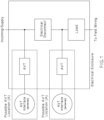
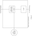
- the tester can be hardwired electrically to components on both the line and load side of each phase of the disconnect being tested.
- verifying the disconnect is open can involve the following steps:
- test sequence is typically initiated by the user at the local interface, although it could also be initiated over a network, via an HMI, or by the AVT if used in combination.
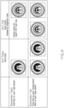
- Two test sequences and their possible signaling results are described in Figure 6 and Figure 8 .
- Figure 6 uses a sequential method of performing the test and adds the condition of all phases of the disconnect being opened to the criteria for a successful absence of voltage test.
- Figure 8 shows a parallel method of performing these two tests, and although they are initiated by the same user prompt, each test is performed and signaled independently.
- Unauthorized access to an electrical, control, or network panel can lead to safety and security hazards that may affect people, equipment, or process.
- Using an access control system at the enclosure level that includes an electronic lock in conjunction with a credential reader users can control or restrict access to authorized people at authorized times.
- a non-hazardous source or energy storage device separate from the primary power (such as the network (PoE), battery, ultracap, etc.)
- voltage is limited to a safe level (50V or less) and the devices will continue to function as long as the secondary power is available, regardless of the status of the main/primary power sources within the enclosure.
- Another method consists of a controller with input for a voltage tester and output to an electronic lock.
- the input and output contacts may be standard I/O, safety-rated and redundant, etc. or some combination.
- the voltage tester is configured to monitor the main power circuit within the enclosure.
- the voltage tester, lock, and controller are all powered from a non-hazardous voltage source independent of the main power circuit (this enables the devices in the system to operate even when the main power is isolated); the system components may be powered by the same source or separate sources (e.g., battery, network (PoE), etc.)
- the controller must have processing power to step through the logic.
- the user requests access to the locked enclosure by testing for voltage. If voltage is present, the enclosure remains locked. If the absence of voltage has been verified, the controller will disengage the lock for a pre-determined amount of time (for instance, 10 seconds) allowing the user to open the door before the controller re-engages the lock. When the door is closed the process can be repeated again.
- Another variation is to include a form of credential authentication in the process to add additional security and prevent unauthorized personnel from accessing equipment.
- This is shown in 12 and 13.
- This method is similar to the basic process but includes an extra step to verify the identity of the user (most likely prior to checking for voltage although the sequence could be interchangeable).
- This additional functionality requires the controller to have two additional inputs for a credential reader (hardware installed on the exterior of the enclosure) and credential verification system.
- the credential verification system will typically consist of a database of credentials approved for access, external to the system linked via network from another system to the controller. However, in some cases this could be maintained within the controller.
- the controller must also contain memory to store the credentials if operating as a standalone device or should the network connection be lost.
- the credential reader must be powered in the same manner as the controller, voltage tester, and lock.
- the user requests access to the system by presenting his or her credentials (something that you have - badge; something that you know - PIN or password; or something that you are - biometrics) to a credential reader.
- the credential reader is used to authenticate the identity of the user. If the credential presented to the reader is verified by the controller as valid based on the most-recent status from the credential verification system, a test for the absence of voltage is then conducted. If voltage is not present, the lock is opened and the user is granted access. However, if the credentials are not validated or the presence of voltage is detected or undeterminable, access is denied and the lock remains engaged.
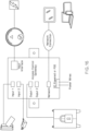
- the process begins by a user requesting access to an electrical panel with the elements installed as shown in Fig. 15 .
- the user may be requesting access based on a workorder he or she received generated in an enterprise asset management system.
- the workorder system may be linked as an input to the controller or it may be operating independently.
- Verifying that the correct equipment is being accessed will help increase safety as many industrial enclosures look similar and every year incidents occur when someone accesses the wrong equipment due to improper labeling or "look-alike" features.
- damage to surrounding equipment or process can occur if the equipment being serviced is not first shut-down properly. Particularly in process industries, this can be hazardous to people, the environment, and surroundings. Thus, being able to set a timeframe for approved access is desirable. This feature can also be used to limit access to a particular area or piece of equipment for service technicians or contractors.
- the next step is to verify the user's credentials.
- the user presents his or her credentials to the reader. This process may include scanning a badge or fob, entering a PIN or password on a keypad, or presenting a fingerprint, among other methods.
- the system completes the process to authenticate the credentials by validating them via the credential verification system whether it is internal to the controller or linked via a separate system. This system may be linked to an active directory with a network connection to a server where credentials are stored.
- the credential may be further enhanced by including additional characteristics such as making sure the employee is authorized to access a particular type of equipment (for example, distinctions can be made by job role (maintenance versus office worker), or between people authorized to access high and low voltage equipment, different types of equipment such as control and automation equipment versus power distribution, equipment from a specific manufacturer, equipment in a particular zone or work cell, etc.) and cross-referencing a training database to ensure credentials are up-to-date.
- additional characteristics such as making sure the employee is authorized to access a particular type of equipment (for example, distinctions can be made by job role (maintenance versus office worker), or between people authorized to access high and low voltage equipment, different types of equipment such as control and automation equipment versus power distribution, equipment from a specific manufacturer, equipment in a particular zone or work cell, etc.) and cross-referencing a training database to ensure credentials are up-to-date.
- access can be contingent on ensuring that required classes or skill audits have been completed and documented within the system. This also sets the foundation to deliver specific need-
- the controller can seek status from the voltage detector. If the voltage test determines that the equipment is de-energized, the lock can be disengaged granting the user access. However, if the panel is energized access can be denied or an additional set-of requirements can be incorporated into the controller logic to determine if access can be granted. For instance, energized work may be dependent on having additional documentation (approved energized work permit, completed job briefing, etc.) in the workorder or other linked system. Additionally, for some tasks, procedures may require more than one person to be present. The access system could be configured to require credentials from more than one user to be presented and authenticated prior to performing energized work or performing any work in a restricted area.
- the lock could engage automatically after a pre-determined period of time or it may be dependent on the position of the door. If a door position sensor is used, the controller could incorporate additional logic to determine when to send an alert or notification if the door has been open too long, if it is unexpectedly open, if it remains open when the panel is re-energized, etc. This further enhances safety and security of the overall system.
- a maintenance worker may be interested in viewing the previous access attempts and when they occurred (similar to how alarms are displayed on HMIs).
- the user could request to review these results via the panel HMI (or other similar visual interface); if access attempts are recent or align with when a problem began, the worker may want to get more information before beginning his work and attempting to open the panel.
- the required hardware will depend on the amount of functionality desired and implemented.
- the logic could be embedded in a stand-alone controller.
- a networked option and/or software to provide easier management of credentials and conditions may provide a useful interface.
- Adding intelligence, via the network capability, to voltage detection and indication systems enables additional information such as status of components related to safety to be available in real time.
- additional display and information activities are now possible. For instance, if switching is performed remotely, the output from the voltage detector could also be displayed via a HMI in remote locations. Additionally, if using a continuous power source (such as PoE), rather than an intermittent source, a positive indication for both the absence and presence of voltage will be displayed as long as power is available.
- Network capability also allows to supplement the physical interface with a more intricate display, for example indicating when voltage was last detected or more information on any other status changes.
- Another embodiment could include an override code or key to allow access to the energized panel in special situations that may be required for certain applications or by qualified personnel if allowed by safety policy.
Landscapes
- Engineering & Computer Science (AREA)
- Computer Security & Cryptography (AREA)
- Microelectronics & Electronic Packaging (AREA)
- Physics & Mathematics (AREA)
- General Physics & Mathematics (AREA)
- Safety Devices In Control Systems (AREA)
- Testing Electric Properties And Detecting Electric Faults (AREA)
- Remote Monitoring And Control Of Power-Distribution Networks (AREA)
Claims (2)
- Procédé pour permettre un accès à une enceinte électrique ayant une déconnexion comprenant :lors du lancement par un utilisateur ou lors d'un changement d'état de la déconnexion, la réalisation automatique des étapes de ;vérification d'une absence de tensionoctroi d'une indication positive d'une absence de tension vérification de l'état de chaque phase de la déconnexion électrique pour s'assurer que des contacts de la déconnexion sont ouvertss'il y a une absence de tension et que les contacts de la déconnexion sont ouvertsouverture d'un verrou sur l'enceinte.
- Procédé selon la revendication 1, comprenant en outre la vérification d'accréditations d'un utilisateur avant l'ouverture du verrou de l'enceinte.
Applications Claiming Priority (2)
| Application Number | Priority Date | Filing Date | Title |
|---|---|---|---|
| US201962882042P | 2019-08-02 | 2019-08-02 | |
| PCT/US2020/043437 WO2021025873A1 (fr) | 2019-08-02 | 2020-07-24 | Procédé pour permettre l'accès à une enceinte électrique |
Publications (2)
| Publication Number | Publication Date |
|---|---|
| EP4007925A1 EP4007925A1 (fr) | 2022-06-08 |
| EP4007925B1 true EP4007925B1 (fr) | 2024-10-02 |
Family
ID=72047108
Family Applications (1)
| Application Number | Title | Priority Date | Filing Date |
|---|---|---|---|
| EP20754532.8A Active EP4007925B1 (fr) | 2019-08-02 | 2020-07-24 | Procédé pour permettre l'accès à une enceinte électrique |
Country Status (4)
| Country | Link |
|---|---|
| US (1) | US20220276287A1 (fr) |
| EP (1) | EP4007925B1 (fr) |
| CA (1) | CA3149502A1 (fr) |
| WO (1) | WO2021025873A1 (fr) |
Families Citing this family (5)
| Publication number | Priority date | Publication date | Assignee | Title |
|---|---|---|---|---|
| US12307838B2 (en) | 2020-04-22 | 2025-05-20 | CareBand Inc. | Method and system for connectivity and control of a hazard-prone environment using a low power wide area network |
| US11640737B2 (en) * | 2020-06-15 | 2023-05-02 | Rockwell Automation Technologies, Inc. | Secure and safe access control |
| US20220018903A1 (en) * | 2020-07-16 | 2022-01-20 | Panduit Corp. | Disconnect Verification |
| US11709187B2 (en) * | 2021-03-19 | 2023-07-25 | Panduit Corp. | Methods to initiate the absence of voltage test over a network remotely |
| US12230955B2 (en) * | 2022-09-20 | 2025-02-18 | Rockwell Automation Technologies, Inc. | Industrial systems with integrated absence of voltage tester (AVT) and positive load indication (PLI) apparatus |
Family Cites Families (11)
| Publication number | Priority date | Publication date | Assignee | Title |
|---|---|---|---|---|
| US5027057A (en) * | 1990-01-30 | 1991-06-25 | Johnson Service Company | Input condition sensing circuit |
| US6861955B2 (en) * | 2003-03-31 | 2005-03-01 | Tom Youssef | Method and circuit for detecting the state of a switch |
| US7611366B2 (en) * | 2005-11-21 | 2009-11-03 | The Southern Company | Meter socket bypass disconnect device |
| US7561412B2 (en) * | 2006-09-29 | 2009-07-14 | Rockwell Automation Technologies, Inc. | System and method for automatically securing a motor control center |
| US20150048814A1 (en) * | 2013-08-13 | 2015-02-19 | Panduit Corp. | Absence of Voltage Indicator with Communication Network Based Secondary Power Source |
| FR3010848B1 (fr) * | 2013-09-16 | 2015-10-02 | Schneider Electric Ind Sas | Dispositif et procede de securite pour installation electrique |
| WO2015152874A1 (fr) * | 2014-03-31 | 2015-10-08 | Schneider Electric USA, Inc. | Indicateur de surcharge avec verrouillage de porte |
| WO2016036952A1 (fr) * | 2014-09-05 | 2016-03-10 | Panduit Corp. | Procédé et dispositif pour détecter de l'absence de tension |
| CN108205107A (zh) * | 2016-12-16 | 2018-06-26 | 陈锡瑜 | 开关接点状态检示装置与方法 |
| US10853594B2 (en) * | 2017-08-31 | 2020-12-01 | Rockwell Automation Technologies, Inc. | Lockout tagout system and method |
| FR3074914B1 (fr) * | 2017-12-07 | 2019-11-29 | Socomec | Procede de detection de l'etat d'un appareil de protection electrique dans une installation electrique et dispositif de detection mettant en oeuvre ledit procede |
-
2020
- 2020-07-24 EP EP20754532.8A patent/EP4007925B1/fr active Active
- 2020-07-24 WO PCT/US2020/043437 patent/WO2021025873A1/fr not_active Ceased
- 2020-07-24 CA CA3149502A patent/CA3149502A1/fr active Pending
- 2020-07-24 US US17/632,050 patent/US20220276287A1/en not_active Abandoned
Also Published As
| Publication number | Publication date |
|---|---|
| CA3149502A1 (fr) | 2021-02-11 |
| WO2021025873A1 (fr) | 2021-02-11 |
| US20220276287A1 (en) | 2022-09-01 |
| EP4007925A1 (fr) | 2022-06-08 |
Similar Documents
| Publication | Publication Date | Title |
|---|---|---|
| AU2021202725B2 (en) | Method and device for detecting the absence of voltage | |
| EP4007925B1 (fr) | Procédé pour permettre l'accès à une enceinte électrique | |
| CN101840221A (zh) | 可移动安全模块及相关方法 | |
| US11740610B2 (en) | Electrical status indication system | |
| EP3798761B1 (fr) | Dispositif et procédé pour l' authentification d' un utilisateur | |
| US10162313B2 (en) | Equipment isolation system | |
| KR101956813B1 (ko) | 생체정보 인식을 구비한 전력설비의 관리시스템 및 방법 | |
| US20170003663A1 (en) | Equipment Isolation System | |
| CN120433417B (zh) | 一种配电室停送电控制方法及系统 | |
| US12562008B1 (en) | Digital LOTO | |
| Kanagalakshmi et al. | Design and implementation of password and fingerprint-enabled circuit breaker using Arduino, IoT and GSM | |
| Dowell III | Two full capacity generators—Why is the calculated emergency power system probability of failure on demand so high? | |
| CN113300466A (zh) | 一种结合ai智能的独立风控告警系统及方法 | |
| Ocheana et al. | Integrating versus Interfacing Safety and Security with Process Control System | |
| JP2022166452A (ja) | 設備管理システム | |
| Brown | Human factors and safety integrity-IEC 61508 | |
| INSTALLATIONS | SECTION 28 13 11 PHYSICAL ACCESS CONTROL SYSTEM (PACS) PART 1–GENERAL 1.1 DESCRIPTION |
Legal Events
| Date | Code | Title | Description |
|---|---|---|---|
| STAA | Information on the status of an ep patent application or granted ep patent |
Free format text: STATUS: UNKNOWN |
|
| STAA | Information on the status of an ep patent application or granted ep patent |
Free format text: STATUS: THE INTERNATIONAL PUBLICATION HAS BEEN MADE |
|
| PUAI | Public reference made under article 153(3) epc to a published international application that has entered the european phase |
Free format text: ORIGINAL CODE: 0009012 |
|
| STAA | Information on the status of an ep patent application or granted ep patent |
Free format text: STATUS: REQUEST FOR EXAMINATION WAS MADE |
|
| 17P | Request for examination filed |
Effective date: 20220228 |
|
| AK | Designated contracting states |
Kind code of ref document: A1 Designated state(s): AL AT BE BG CH CY CZ DE DK EE ES FI FR GB GR HR HU IE IS IT LI LT LU LV MC MK MT NL NO PL PT RO RS SE SI SK SM TR |
|
| DAV | Request for validation of the european patent (deleted) | ||
| DAX | Request for extension of the european patent (deleted) | ||
| GRAP | Despatch of communication of intention to grant a patent |
Free format text: ORIGINAL CODE: EPIDOSNIGR1 |
|
| STAA | Information on the status of an ep patent application or granted ep patent |
Free format text: STATUS: GRANT OF PATENT IS INTENDED |
|
| RIC1 | Information provided on ipc code assigned before grant |
Ipc: H05K 5/02 20060101ALI20240415BHEP Ipc: G01R 19/155 20060101AFI20240415BHEP |
|
| INTG | Intention to grant announced |
Effective date: 20240429 |
|
| GRAS | Grant fee paid |
Free format text: ORIGINAL CODE: EPIDOSNIGR3 |
|
| GRAA | (expected) grant |
Free format text: ORIGINAL CODE: 0009210 |
|
| STAA | Information on the status of an ep patent application or granted ep patent |
Free format text: STATUS: THE PATENT HAS BEEN GRANTED |
|
| AK | Designated contracting states |
Kind code of ref document: B1 Designated state(s): AL AT BE BG CH CY CZ DE DK EE ES FI FR GB GR HR HU IE IS IT LI LT LU LV MC MK MT NL NO PL PT RO RS SE SI SK SM TR |
|
| REG | Reference to a national code |
Ref country code: GB Ref legal event code: FG4D |
|
| REG | Reference to a national code |
Ref country code: CH Ref legal event code: EP |
|
| REG | Reference to a national code |
Ref country code: DE Ref legal event code: R096 Ref document number: 602020038716 Country of ref document: DE |
|
| REG | Reference to a national code |
Ref country code: IE Ref legal event code: FG4D |
|
| REG | Reference to a national code |
Ref country code: LT Ref legal event code: MG9D |
|
| REG | Reference to a national code |
Ref country code: NL Ref legal event code: MP Effective date: 20241002 |
|
| REG | Reference to a national code |
Ref country code: AT Ref legal event code: MK05 Ref document number: 1728857 Country of ref document: AT Kind code of ref document: T Effective date: 20241002 |
|
| PG25 | Lapsed in a contracting state [announced via postgrant information from national office to epo] |
Ref country code: NL Free format text: LAPSE BECAUSE OF FAILURE TO SUBMIT A TRANSLATION OF THE DESCRIPTION OR TO PAY THE FEE WITHIN THE PRESCRIBED TIME-LIMIT Effective date: 20241002 |
|
| PG25 | Lapsed in a contracting state [announced via postgrant information from national office to epo] |
Ref country code: NL Free format text: LAPSE BECAUSE OF FAILURE TO SUBMIT A TRANSLATION OF THE DESCRIPTION OR TO PAY THE FEE WITHIN THE PRESCRIBED TIME-LIMIT Effective date: 20241002 |
|
| PG25 | Lapsed in a contracting state [announced via postgrant information from national office to epo] |
Ref country code: HR Free format text: LAPSE BECAUSE OF FAILURE TO SUBMIT A TRANSLATION OF THE DESCRIPTION OR TO PAY THE FEE WITHIN THE PRESCRIBED TIME-LIMIT Effective date: 20241002 Ref country code: IS Free format text: LAPSE BECAUSE OF FAILURE TO SUBMIT A TRANSLATION OF THE DESCRIPTION OR TO PAY THE FEE WITHIN THE PRESCRIBED TIME-LIMIT Effective date: 20250202 Ref country code: PT Free format text: LAPSE BECAUSE OF FAILURE TO SUBMIT A TRANSLATION OF THE DESCRIPTION OR TO PAY THE FEE WITHIN THE PRESCRIBED TIME-LIMIT Effective date: 20250203 |
|
| PG25 | Lapsed in a contracting state [announced via postgrant information from national office to epo] |
Ref country code: FI Free format text: LAPSE BECAUSE OF FAILURE TO SUBMIT A TRANSLATION OF THE DESCRIPTION OR TO PAY THE FEE WITHIN THE PRESCRIBED TIME-LIMIT Effective date: 20241002 |
|
| PG25 | Lapsed in a contracting state [announced via postgrant information from national office to epo] |
Ref country code: BG Free format text: LAPSE BECAUSE OF FAILURE TO SUBMIT A TRANSLATION OF THE DESCRIPTION OR TO PAY THE FEE WITHIN THE PRESCRIBED TIME-LIMIT Effective date: 20241002 |
|
| PG25 | Lapsed in a contracting state [announced via postgrant information from national office to epo] |
Ref country code: ES Free format text: LAPSE BECAUSE OF FAILURE TO SUBMIT A TRANSLATION OF THE DESCRIPTION OR TO PAY THE FEE WITHIN THE PRESCRIBED TIME-LIMIT Effective date: 20241002 |
|
| PG25 | Lapsed in a contracting state [announced via postgrant information from national office to epo] |
Ref country code: NO Free format text: LAPSE BECAUSE OF FAILURE TO SUBMIT A TRANSLATION OF THE DESCRIPTION OR TO PAY THE FEE WITHIN THE PRESCRIBED TIME-LIMIT Effective date: 20250102 |
|
| PG25 | Lapsed in a contracting state [announced via postgrant information from national office to epo] |
Ref country code: GR Free format text: LAPSE BECAUSE OF FAILURE TO SUBMIT A TRANSLATION OF THE DESCRIPTION OR TO PAY THE FEE WITHIN THE PRESCRIBED TIME-LIMIT Effective date: 20250103 Ref country code: LV Free format text: LAPSE BECAUSE OF FAILURE TO SUBMIT A TRANSLATION OF THE DESCRIPTION OR TO PAY THE FEE WITHIN THE PRESCRIBED TIME-LIMIT Effective date: 20241002 Ref country code: AT Free format text: LAPSE BECAUSE OF FAILURE TO SUBMIT A TRANSLATION OF THE DESCRIPTION OR TO PAY THE FEE WITHIN THE PRESCRIBED TIME-LIMIT Effective date: 20241002 |
|
| PG25 | Lapsed in a contracting state [announced via postgrant information from national office to epo] |
Ref country code: CZ Free format text: LAPSE BECAUSE OF FAILURE TO SUBMIT A TRANSLATION OF THE DESCRIPTION OR TO PAY THE FEE WITHIN THE PRESCRIBED TIME-LIMIT Effective date: 20241002 Ref country code: PL Free format text: LAPSE BECAUSE OF FAILURE TO SUBMIT A TRANSLATION OF THE DESCRIPTION OR TO PAY THE FEE WITHIN THE PRESCRIBED TIME-LIMIT Effective date: 20241002 |
|
| PG25 | Lapsed in a contracting state [announced via postgrant information from national office to epo] |
Ref country code: RS Free format text: LAPSE BECAUSE OF FAILURE TO SUBMIT A TRANSLATION OF THE DESCRIPTION OR TO PAY THE FEE WITHIN THE PRESCRIBED TIME-LIMIT Effective date: 20250102 |
|
| PG25 | Lapsed in a contracting state [announced via postgrant information from national office to epo] |
Ref country code: SM Free format text: LAPSE BECAUSE OF FAILURE TO SUBMIT A TRANSLATION OF THE DESCRIPTION OR TO PAY THE FEE WITHIN THE PRESCRIBED TIME-LIMIT Effective date: 20241002 |
|
| REG | Reference to a national code |
Ref country code: DE Ref legal event code: R097 Ref document number: 602020038716 Country of ref document: DE |
|
| PG25 | Lapsed in a contracting state [announced via postgrant information from national office to epo] |
Ref country code: DK Free format text: LAPSE BECAUSE OF FAILURE TO SUBMIT A TRANSLATION OF THE DESCRIPTION OR TO PAY THE FEE WITHIN THE PRESCRIBED TIME-LIMIT Effective date: 20241002 |
|
| PG25 | Lapsed in a contracting state [announced via postgrant information from national office to epo] |
Ref country code: EE Free format text: LAPSE BECAUSE OF FAILURE TO SUBMIT A TRANSLATION OF THE DESCRIPTION OR TO PAY THE FEE WITHIN THE PRESCRIBED TIME-LIMIT Effective date: 20241002 |
|
| PG25 | Lapsed in a contracting state [announced via postgrant information from national office to epo] |
Ref country code: RO Free format text: LAPSE BECAUSE OF FAILURE TO SUBMIT A TRANSLATION OF THE DESCRIPTION OR TO PAY THE FEE WITHIN THE PRESCRIBED TIME-LIMIT Effective date: 20241002 |
|
| PG25 | Lapsed in a contracting state [announced via postgrant information from national office to epo] |
Ref country code: SK Free format text: LAPSE BECAUSE OF FAILURE TO SUBMIT A TRANSLATION OF THE DESCRIPTION OR TO PAY THE FEE WITHIN THE PRESCRIBED TIME-LIMIT Effective date: 20241002 |
|
| PG25 | Lapsed in a contracting state [announced via postgrant information from national office to epo] |
Ref country code: IT Free format text: LAPSE BECAUSE OF FAILURE TO SUBMIT A TRANSLATION OF THE DESCRIPTION OR TO PAY THE FEE WITHIN THE PRESCRIBED TIME-LIMIT Effective date: 20241002 |
|
| PLBE | No opposition filed within time limit |
Free format text: ORIGINAL CODE: 0009261 |
|
| STAA | Information on the status of an ep patent application or granted ep patent |
Free format text: STATUS: NO OPPOSITION FILED WITHIN TIME LIMIT |
|
| PG25 | Lapsed in a contracting state [announced via postgrant information from national office to epo] |
Ref country code: SE Free format text: LAPSE BECAUSE OF FAILURE TO SUBMIT A TRANSLATION OF THE DESCRIPTION OR TO PAY THE FEE WITHIN THE PRESCRIBED TIME-LIMIT Effective date: 20241002 |
|
| 26N | No opposition filed |
Effective date: 20250703 |
|
| PGFP | Annual fee paid to national office [announced via postgrant information from national office to epo] |
Ref country code: DE Payment date: 20250729 Year of fee payment: 6 |
|
| PGFP | Annual fee paid to national office [announced via postgrant information from national office to epo] |
Ref country code: GB Payment date: 20250728 Year of fee payment: 6 |
|
| PGFP | Annual fee paid to national office [announced via postgrant information from national office to epo] |
Ref country code: FR Payment date: 20250725 Year of fee payment: 6 |
|
| REG | Reference to a national code |
Ref country code: CH Ref legal event code: H13 Free format text: ST27 STATUS EVENT CODE: U-0-0-H10-H13 (AS PROVIDED BY THE NATIONAL OFFICE) Effective date: 20260224 |
|
| PG25 | Lapsed in a contracting state [announced via postgrant information from national office to epo] |
Ref country code: LU Free format text: LAPSE BECAUSE OF NON-PAYMENT OF DUE FEES Effective date: 20250724 |
|
| REG | Reference to a national code |
Ref country code: BE Ref legal event code: MM Effective date: 20250731 |
|
| PG25 | Lapsed in a contracting state [announced via postgrant information from national office to epo] |
Ref country code: BE Free format text: LAPSE BECAUSE OF NON-PAYMENT OF DUE FEES Effective date: 20250731 |
|
| PG25 | Lapsed in a contracting state [announced via postgrant information from national office to epo] |
Ref country code: CH Free format text: LAPSE BECAUSE OF NON-PAYMENT OF DUE FEES Effective date: 20250731 |