EP4008041B1 - Guide d'ondes electromagnetiques - Google Patents
Guide d'ondes electromagnetiques Download PDFInfo
- Publication number
- EP4008041B1 EP4008041B1 EP20751509.9A EP20751509A EP4008041B1 EP 4008041 B1 EP4008041 B1 EP 4008041B1 EP 20751509 A EP20751509 A EP 20751509A EP 4008041 B1 EP4008041 B1 EP 4008041B1
- Authority
- EP
- European Patent Office
- Prior art keywords
- tubes
- hollow
- tube
- primary
- waveguide
- Prior art date
- Legal status (The legal status is an assumption and is not a legal conclusion. Google has not performed a legal analysis and makes no representation as to the accuracy of the status listed.)
- Active
Links
Images



Classifications
-
- G—PHYSICS
- G02—OPTICS
- G02B—OPTICAL ELEMENTS, SYSTEMS OR APPARATUS
- G02B6/00—Light guides; Structural details of arrangements comprising light guides and other optical elements, e.g. couplings
- G02B6/02—Optical fibres with cladding with or without a coating
- G02B6/02295—Microstructured optical fibre
- G02B6/02314—Plurality of longitudinal structures extending along optical fibre axis, e.g. holes
- G02B6/02342—Plurality of longitudinal structures extending along optical fibre axis, e.g. holes characterised by cladding features, i.e. light confining region
- G02B6/02366—Single ring of structures, e.g. "air clad"
-
- G—PHYSICS
- G02—OPTICS
- G02B—OPTICAL ELEMENTS, SYSTEMS OR APPARATUS
- G02B6/00—Light guides; Structural details of arrangements comprising light guides and other optical elements, e.g. couplings
- G02B6/02—Optical fibres with cladding with or without a coating
- G02B6/02295—Microstructured optical fibre
- G02B6/02314—Plurality of longitudinal structures extending along optical fibre axis, e.g. holes
- G02B6/02319—Plurality of longitudinal structures extending along optical fibre axis, e.g. holes characterised by core or core-cladding interface features
- G02B6/02323—Core having lower refractive index than cladding, e.g. photonic band gap guiding
- G02B6/02328—Hollow or gas filled core
-
- G—PHYSICS
- G02—OPTICS
- G02B—OPTICAL ELEMENTS, SYSTEMS OR APPARATUS
- G02B6/00—Light guides; Structural details of arrangements comprising light guides and other optical elements, e.g. couplings
- G02B6/02—Optical fibres with cladding with or without a coating
- G02B6/02295—Microstructured optical fibre
- G02B6/02314—Plurality of longitudinal structures extending along optical fibre axis, e.g. holes
- G02B6/02342—Plurality of longitudinal structures extending along optical fibre axis, e.g. holes characterised by cladding features, i.e. light confining region
- G02B6/02361—Longitudinal structures forming multiple layers around the core, e.g. arranged in multiple rings with each ring having longitudinal elements at substantially the same radial distance from the core, having rotational symmetry about the fibre axis
-
- G—PHYSICS
- G02—OPTICS
- G02B—OPTICAL ELEMENTS, SYSTEMS OR APPARATUS
- G02B6/00—Light guides; Structural details of arrangements comprising light guides and other optical elements, e.g. couplings
- G02B6/02—Optical fibres with cladding with or without a coating
- G02B6/024—Optical fibres with cladding with or without a coating with polarisation maintaining properties
-
- H—ELECTRICITY
- H01—ELECTRIC ELEMENTS
- H01P—WAVEGUIDES; RESONATORS, LINES, OR OTHER DEVICES OF THE WAVEGUIDE TYPE
- H01P3/00—Waveguides; Transmission lines of the waveguide type
- H01P3/12—Hollow waveguides
-
- H—ELECTRICITY
- H01—ELECTRIC ELEMENTS
- H01P—WAVEGUIDES; RESONATORS, LINES, OR OTHER DEVICES OF THE WAVEGUIDE TYPE
- H01P3/00—Waveguides; Transmission lines of the waveguide type
- H01P3/12—Hollow waveguides
- H01P3/127—Hollow waveguides with a circular, elliptic, or parabolic cross-section
Definitions
- the present invention relates to the field of guiding electromagnetic waves, in particular by the Inhibited Coupling mechanism, and in particular waves in the fields of optics, Tera Hertz and Microwaves.
- the invention provides a waveguide allowing single-mode guidance and, in certain cases, preservation of the polarization of the electromagnetic wave in the waveguide.
- the patent document WO2019/071921A1 discloses a hollow core anti-resonant optical fiber having multiple anti-resonant layers.
- the present invention relates to an electromagnetic waveguide, based on the inhibited coupling mechanism, comprising a hollow central part whose contour is at least partly defined by a first set of at least seven primary hollow tubes, distributed in an annular manner around the central hollow part, said primary hollow tubes being substantially of the same size, distant from each other.
- said waveguide further comprises a second set of tubes comprising at least one hollow secondary tube, when there are several of them, these secondary tubes are positioned in an annular manner around the primary tubes, the area of the at least one hollow secondary tube being between 0.35 and 0.50 times the area of the central hollow part.
- the primary tubes can be attached to the secondary tubes or to a wall of a duct carrying the secondary tubes.
- the area of the central hollow part is understood to be the area of the inscribed circle, internal to the annular arrangement of the first set of hollow tubes.
- the ratio, or scaling law, between the area of the central hollow part and the area of the at least one hollow secondary tube makes it possible to limit the losses of the waveguide according to the invention.
- the waveguide according to the invention in particular achieves monomodal guidance of the waves, for example by filtering the first four higher order modes of the core in order to retain only the fundamental mode of the core.
- the at least one hollow secondary tube is positioned opposite a first hollow tube.
- the at least one hollow secondary tube is positioned opposite a gap between two primary hollow tubes.
- the primary hollow tubes may have a section composed of a first circle comprising at least one inscribed circle, in the case of several inscribed circles, these inscribed circles are distributed over the internal circumference of the first circle, said inscribed circles being distant from each other.
- the major axis of said ellipse is positioned radially relative to the center of the hollow central part, also called the hollow core.
- the primary tubes have a section in the shape of a barred ellipse, said ellipse is divided in two by a segment.
- the segment dividing the ellipse section in two is located on the minor axis of said ellipse.
- the secondary tubes secondary tubes can be distant from each other.
- the secondary tubes may touch each other
- the sections of the secondary tubes can form a grid comprising at least one unit element.
- the grid may consist of several unit elements of different shapes.
- a unit element can be polyhedral in shape.
- the sections of the secondary tubes can, for example, form a grid of hexagonal unit elements.
- the sections of the secondary tubes can, for example, form a grid of triangular unit elements.
- the sections of the secondary tubes may, for example, form a grid of substantially square unit elements.
- the sections of the secondary tubes can, for example, form a grid of rectangular unit elements.
- the secondary tubes may form a grid having more than one type of unit element and arranged to form a mesh, triangular, hexagonal, square or a combination of these arrangements.
- the secondary tubes whose outline is composed of an arc of a circle and three sides of a polygon, can be distributed so as to form at least one corolla surrounding the primary tubes.
- Each of the shapes composing the corolla can be contiguous with its neighbor.
- the waveguide may be an optical fiber.
- the optical fiber can be a micro-structured optical fiber.
- Both primary and secondary tubes can be made of dielectric material.
- the first and secondary tubes can have walls of the same thickness, for example between 100nm and 2000nm.
- the hollow central part, the first and secondary tubes can be filled with a gas such as air.
- the waveguide according to the invention guides waves in particular by inhibited coupling.
- the distance ⁇ rr between the at least one secondary tube and the internal wall of the sheath is preferably less than 0.2*r tin for the case of a circular primary tube or less than 0.2* ⁇ (Area in / ⁇ ) for a primary tube having an area equal to Area in .
- each primary tube can be fixed to the wall of a secondary tube.
- An objective of the present invention is in particular to reduce the losses for a given order propagation mode and to increase the losses for higher order propagation modes.
- the object of the present invention is in particular to propose an electromagnetic waveguide having a hollow central part delimited by a first set of tubes isolated from each other, carried by a first tubular structure, and arranged so as to form a ring, called for example an internal ring or first ring, and a second annular structure or external ring.
- the second annular structure may advantageously comprise a second set of tubes positioned around the ring formed by the tubes of the internal ring.
- the present invention can be applied in different fields and in particular for guiding waves in the field of optics, Tera Hertz, microwaves.
- FIG. 1a represents a first example of an electromagnetic waveguide 1 according to the invention.
- the first electromagnetic waveguide 1 may be a hollow optical fiber with inhibited coupling guidance.
- the waveguide 1 comprises a hollow central part or hollow core 2 which can be filled with either air, a neutral gas or a vacuum.
- the hollow core 2 can have a minimum diameter 2 R c , R c corresponding to a radius of the hollow core 2.
- Around the hollow core 2 is a first ring 4 or cylindrical inner ring 4 or first annular structure 4, contained in the vacuum like the hollow core 2, extending over the entire length of the waveguide.
- the inner ring 4 has an inner radius of R c and an outer radius of R st .
- the inner ring 4 comprises several primary hollow tubes 8, 9, 10, 11, 12, 13, 14 spaced apart from each other.
- the first waveguide 1 may comprise seven primary tubes of circular section.
- a distance between two primary tubes may be ⁇ tt .
- the distance ⁇ tt is preferably greater than zero.
- the distance ⁇ tt is preferably, but not limited to, equal to or less than 0.1 r tin for tubes of the first ring of circular shape of radius r tin , or 0.1 Aire in / ⁇ for a non-circular tube having an area of Area in .
- the distance ⁇ tt can be between 800nm and 2 ⁇ m.
- a waveguide according to the invention advantageously comprises at least seven primary tubes.
- the waveguide may however comprise more than seven primary tubes.
- a waveguide comprising six primary tubes has a core size smaller than a waveguide comprising seven primary tubes.
- the use of at least seven primary tubes makes it possible to minimize losses, in particular because the core has a larger size than with seven primary tubes.
- the primary tubes may be carried by an internal wall 5 of a sheath 3.
- the primary tubes 8, 9, 10, 11, 12, 13, 14 are represented according to a first circular section shape 16 as represented in the Figure 1b .
- a second shape may be of circular section 17 and comprise at least one other tube of circular section 18, 100, 101, 102.
- the second form may comprise a tube of circular section 18.
- a third form may alternatively comprise two or three tubes 100, 101, 102 contained in a first tube 19, of circular shape.
- the tubes 100, 101, 102 included in the primary tubes 19 may be distant from each other, and in contact with the internal surface of the primary tubes 19.
- a fourth cross-sectional shape for the primary tubes may be an ellipsoidal shape 103, 104 as shown in FIG. Figure 1b
- the major axis of the ellipse may be oriented radially, i.e. in the direction of the center of the first waveguide 1.
- the ellipse 104 may be a barred ellipse, for example according to its small diameter.
- the bar 105 may extend over the entire length of the first elliptical section tube 104.
- the primary tubes have a different cross-sectional shape from each other.
- the first waveguide 1 further comprises the sheath 3 which constitutes a second ring also called external ring 3 comprising at least one hollow cylindrical secondary tube 6 of diameter 2 R tout .
- the radius R tout can be included in the interval [ 0.6 ⁇ R c ; 0.7 ⁇ R c ] .
- R tout 0.66 ⁇ R c .
- the interior of the outer ring 3 is formed from a solid material into which the at least one hollow secondary tube 6 is inserted.
- the distance between the at least one secondary tube 6 and the external surface of the internal ring 4 is ⁇ rr .
- ⁇ rr can be negative.
- ⁇ rr ⁇ 0.2 r tin for the case of a circular tube or ⁇ rr ⁇ 0.2 Aire in / ⁇ for a tube having an area equal to A ire in .
- the secondary tube 6 is positioned opposite a gap between two consecutive primary tubes 8 and 14, for example.
- the secondary tube 6 can alternatively be positioned opposite a first tube 8, 9, 10, 11, 12, 13, 14.
- a first shape may be a circular section 106
- a second shape may be a polygonal section shape and for example square 107, or triangular
- a third shape may be a hexagonal section 108.
- a fourth shape 109 may be a section composed of a portion of a circle closed by a portion of a hexagon or polygon, for example with three branches. The fourth shape 109 may be called a petal shape.
- the secondary tubes of circular section can be spaced apart from each other.
- the sections of the secondary tubes may form a grid comprising at least one unit element of one of the section shapes shown in the Figure 1c .
- the sections of the secondary tubes may form a grid of hexagonal unit elements.
- the sections of the secondary tubes may form a grid of triangular unit elements.
- the sections of the secondary tubes may form a grid of substantially square unit elements.
- the sections of the secondary tubes may form a grid comprising more than one unit element, said unit elements being arranged to form a triangular, hexagonal, square mesh or a combination of these arrangements.
- a second tubular structure 7 can form a jacket of the waveguide according to the invention.
- the secondary tube 6 can be carried by the second tubular structure 7.
- such a waveguide makes it possible to maintain fairly low energy losses for the mode to be propagated and to increase the losses for the higher order modes.
- the higher order modes can leak through the gaps between two consecutive primary tubes when they are not placed opposite the secondary tubes.
- the higher order modes can leak through the secondary tubes when these are in contact with the primary tubes.
- FIG. 2 represents a second example of a waveguide 20 according to the invention.
- the second waveguide 20 also comprises two secondary tubes 21, 22 forming part of an outer ring 25.
- the two secondary tubes 21, 22 are positioned opposite core 2 and two intervals between two consecutive primary tubes 200, 201 and 204, 205.
- the configuration of the secondary tubes opposite a gap between two primary tubes is particularly relevant when the distance between two consecutive primary tubes is relatively large.
- a second tubular structure 26 can form a jacket of the waveguide according to the invention.
- the secondary tubes 21, 22 can be carried by the second tubular structure 26.
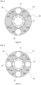
- FIG. 3 represents a third example of a waveguide 30 with monomodal wave propagation according to the invention.
- the second waveguide 30, like the first waveguide 1, comprises a core 38 surrounded by a first ring 39 consisting of eight primary tubes 300, 301, 302, 303, 304, 305, 306, 307.
- the eight primary tubes 300, 301, 302, 303, 304, 305, 306, 307 are supported by the inner wall 37 of a sheath 35 forming an outer ring.
- the second waveguide 30 also comprises four secondary tubes 31, 32, 33, 34 forming part of a second ring 35.
- the four secondary tubes 31, 32, 33, 34 are positioned opposite a gap between two of the primary tubes of the first ring 39. Respectively on the Figure 3 , the four secondary tubes 31, 32, 33, 34 are positioned opposite the interstices between the primary tubes 304 and 305, 306 and 307, 300 and 301, 302 and 303.
- a second tubular structure 36 can form a jacket of the waveguide according to the invention.
- the secondary tubes 31, 32, 33, 34 can be carried by the second tubular structure 36.
- FIG. 4 represents a fourth example of a waveguide 40 with monomodal wave propagation according to the invention.
- the fourth waveguide 40 like the third waveguide 30, comprises a core 41 surrounded by a first ring 42 consisting of eight primary tubes 400, 401, 402, 403, 404, 405, 406, 407.
- the eight primary tubes 400, 401, 402, 403, 404, 405, 406, 407 are supported by the inner wall 44 of a sheath 43 forming an outer ring.
- the eight primary tubes 400, 401, 402, 403, 404, 405, 406, 407 are for example but not necessarily regularly distributed in the first ring 42.
- the fourth waveguide 40 also comprises two secondary tubes 47, 48 forming part of a second ring 43.
- the two secondary tubes 47, 48 are positioned opposite one of the primary tubes of the first ring 42.
- a second tubular structure 45 may form a jacket of the waveguide according to the invention.
- the secondary tubes 47, 48 may be carried by the second tubular structure 45.
- the alignment of primary tubes 47, 48 with secondary tubes 402, 406 allows unwanted propagation modes to be leaked.
- This type of waveguide architecture is particularly relevant when the spaces between the primary tubes are relatively small.
- FIG. 5 represents a fifth example of a single-mode wave propagation waveguide 50 according to the invention.
- the fifth waveguide 50 comprises eight primary tubes 501, 502, 503, 504, 505, 506, 507, 508 distributed over a first ring 57 around the core 56.
- the primary tubes 501, 502, 503, 504, 505, 506, 507, 508 may be carried by the internal wall 59 of a sheath 55 forming an external ring.
- the fifth waveguide 50 further comprises a second ring 55 comprising secondary tubes 51, 53, 52, 54.
- the secondary tubes are respectively located opposite the primary tubes 502, 504, 506, 508.
- the secondary tubes 502, 504, 506, 508 may be distant from each other.
- FIG. 6 represents a sixth example of a single-mode propagation waveguide 80 according to the invention.
- the sixth waveguide 80 comprises eight primary tubes 84, 85, 86, 87, 88, 89, 800, 801 distributed over a first ring 82 around the core 81.
- the sixth waveguide 80 further comprises a second ring 83 comprising eight secondary tubes 802, 803, 804, 805, 806, 807, 808, 809.
- the secondary tubes 802, 803, 804, 805, 806, 807, 808, 809 are respectively located opposite the primary tubes 84, 85, 86, 87, 88, 89, 800, 801.
- each primary tube 84, 85, 86, 87, 88, 89, 800, 801 is in direct contact with the secondary tube 802, 803, 804, 805, 806, 807, 808, 809 respectively opposite.
- the primary and secondary tubes are thus fixed two by two and suspended in the void.
- Each secondary tube is fixed to a wall 810, which can be the internal wall of a sheath or other jacket for example.
- the seventh waveguide 90 is a polarization-maintaining waveguide. Polarization maintenance is ensured by the presence of rods, for example four rods, distributed in every other gap between primary tubes forming part of a first ring surrounding a hollow core 91.
- the rods may have a section whose area is ⁇ 0.2xArea in (the area of a tube of the first set).
- the seventh waveguide 90 may comprise a first ring 92 comprising for example eight primary tubes 95, 96, 97, 98, 99, 900, 901, 902 surrounding the core hollow 91. Further, the seventh waveguide 90 may include four rods 904, 905, 906, 907 positioned in the first ring 92. For example, a first rod 904 may be inserted between a primary tube 95 and a subsequent primary tube 96 on the first ring 92 by rotating clockwise. A second rod 905 may be inserted between a primary tube 97 and a primary tube 98. A third rod 906 may be inserted between a primary tube 99 and a primary tube 900. The gap between primary tubes 902 and 95, 96 and 97, 98 and 99, 900 and 901 does not include a rod.
- the rods 904, 905, 906, 907 like the first tubes 95, 96, 97, 98, 99, 900, 901, 902 are carried by an internal wall of a sheath 93 surrounding the first ring 92.
- the positioning of the rods 904, 905, 906, 907 in every other gap separating the primary tubes makes it possible to maintain the polarization of the wave propagating in the seventh waveguide.
- FIG 8 represents an example of an eighth single-mode, polarization-maintaining waveguide 110 according to the invention.
- the eighth waveguide 110 as shown in the Figure 10 combines the advantages and features of the seventh polarization-maintaining 90 waveguide and the third single-mode propagation 30 waveguide.
- the eighth waveguide 110 comprises a hollow core 111 surrounded by a first ring 112.
- the first ring 112 comprises eight primary tubes 1120, 1121, 1122, 1123, 1124, 1125, 1126, 1127.
- a rod 1128, 1129, 1130, 1131 In every other interval between two consecutive primary tubes is inserted a rod 1128, 1129, 1130, 1131.
- a first rod 1128 can be inserted between two primary tubes 1120, 1121
- a second rod 1129 can be inserted between two primary tubes 1122 and 1123
- a third rod 1130 can be inserted between two primary tubes 1124 and 1125
- a fourth rod 1131 can be inserted between two primary tubes 1126 and 1127.
- the eighth waveguide 110 comprises a second ring 113 comprising four secondary tubes 116, 117, 118, 119.
- the secondary tubes may for example be positioned opposite the intervals between the primary tubes 1121 and 1122, 1123 and 1123, 1125 and 1126, 1127 and 1120, between which no rod has been inserted.
- the positioning of the rods 1128, 1129, 1130, 1131 in every other gap separating the primary tubes 1120, 1121, 1122, 1123, 1124, 1125, 1126, 1127 makes it possible to maintain the polarization of the wave propagating in the waveguide according to the invention.
- the positioning of the secondary tubes 116, 117, 118, 119 opposite every second gap separating the primary tubes, said second gaps not comprising rods, makes it possible to increase the losses for the modes of orders higher than the mode preferentially guided in the core of the guide. waves according to the invention.
- a first type of rods can be a solid cylindrical tube 150.
- a second type of rod can be a solid tube with an ellipsoidal section 151, also called an elliptical rod 151.
- a third type of rod can be a hollow cylinder 153.
- a fourth type of rod 154 can be a hollow cylindrical tube with a longitudinal separation, dividing said cylinder into two cylinder portions, the fourth type of rod can be called a barred tube 154.
- a fifth type of rod 152 can be a hollow tube with an elliptical section with a separation along the entire length of the rod 152 along the major axis of the elliptical section, the fifth type of guide can be called a barred elliptical tube 152.
- FIG. 10 represents a ninth example of a waveguide 120 according to the invention.
- the ninth waveguide 120 comprises a hollow core 121 surrounded by a first ring 122.
- the first ring 112 may comprise nine primary tubes 123.
- the primary tubes 123 may have one of the shapes shown in the Figure 1b
- the primary tubes 123 may be carried by the first annular structure 124.
- the first ring 122 is surrounded by a second ring 125.
- the second ring 125 may comprise secondary tubes 126 in the form of petals 109, as shown in the Figure 1c .
- the second ring 125 comprises eleven primary tubes 126 in the form of petals distributed homogeneously on this second ring 125.
- the petals are contiguous and form a first corolla. It is possible in an alternative embodiment to have at least a second corolla surrounding the first corolla.
- the secondary tubes 126 are carried by a sheath or jacket 127 surrounding the second ring 125.
- FIG. 11 represents a tenth example of a waveguide 130 according to the invention.
- the tenth waveguide 130 comprises a hollow core 131 surrounded by a first ring 132.
- the first ring 132 comprises, for example, nine primary tubes 133.
- the primary tubes 133 may have one of the shapes shown in the Figure 1b .
- the first tubes 133 can be supported by a grid 134.
- the tenth waveguide 130 further comprises a second ring 135 comprising secondary tubes 136 forming a grid 134 of square unitary pattern.
- the grid is cut so as to form the second ring 135 around the first ring 132 and so as to have an external contour 137 of circular shape.
- a jacket 138 is shown, said jacket 138 surrounding the second ring 135.
- FIG. 12 represents an eleventh example of a waveguide 140 according to the invention.
- the eleventh waveguide 140 comprises a hollow core 141.
- the hollow core 141 is surrounded by a first ring 142 comprising primary hollow tubes 143.
- a first ring 142 comprising primary hollow tubes 143.
- seven primary hollow tubes 143 are shown.
- the primary hollow tubes 143 may be of any of the shapes shown in the Figure 1b .
- the first hollow tubes 143 may be carried by a first tubular structure 145.
- the eleventh waveguide 140 further comprises a second ring 146.
- the secondary tubes of the second ring 146 are arranged to form a hexagonal unitary pattern grid such as a Kagomé structure, for example.
- the hexagonal unitary pattern grid is cut to have a circular inner contour and an outer contour.
- the secondary tubes forming the second ring may form a grid comprising at least one unit element.
- the unit element may have a section of one of the shapes shown in the Figures 1b, 1c , or even a triangular shape.
- the grid may be composed of several different unitary patterns among the shapes represented on the Figures 1b, 1c , a triangular shape.
- the secondary tubes can form a grid of triangular, or substantially square, or rectangular unit elements.
- a jacket 147 of the eleventh waveguide is also shown, surrounding the second ring 146.
- FIG. 13a represents an example of a first alternative structure of a first ring 150 of a waveguide according to the invention.
- FIG. 13a an example of an arrangement of primary tubes 151 according to the invention is shown.
- the primary tubes 151 shown in the Figure 13a are of the second form of the primary tubes 16 shown on the Figure 1b .
- Each first tube 151 therefore comprises another tube with circular section 152 as shown in the Figure 1b .
- nine primary tubes 151 are shown for the example.
- the other nine tubes are for example arranged around the perimeter of the internal diameter of the first ring 150, so as to maximize their distance from the center of the first ring 150.
- Figure 13b represents a first ring 160 comprising nine primary tubes 161.
- Each of the nine primary tubes 161 comprises three other tubes 163.
- the other tubes 163 are for example carried by the inner circumference of the primary tubes 161.
- the other tubes 163 are arranged so that an interval between two other tubes 163 is located opposite the center of the first ring 160.
- FIG. 13c represents a third alternative of a structure of a first ring 170 of a waveguide according to the invention.
- the first ring 170 surrounds a hollow core 171.
- the primary tubes 172 shown in Figure 15c have an ellipsoidal type section 103 as shown in the Figure 1b .
- the primary tubes 172 of ellipsoidal section can be arranged so that the major axis of the ellipse forming the section of each first tube 172 is directed towards the center of the core 171.
- the bar 183 of the ellipse 182 can be arranged in the ellipse 182 according to its small diameter for example.
Landscapes
- Physics & Mathematics (AREA)
- General Physics & Mathematics (AREA)
- Optics & Photonics (AREA)
- Waveguides (AREA)
- Chemical Vapour Deposition (AREA)
Applications Claiming Priority (2)
| Application Number | Priority Date | Filing Date | Title |
|---|---|---|---|
| FR1908906A FR3099649B1 (fr) | 2019-08-02 | 2019-08-02 | Guide d’ondes électromagnétiques |
| PCT/EP2020/071732 WO2021023674A1 (fr) | 2019-08-02 | 2020-07-31 | Guide d'ondes electromagnetiques |
Publications (2)
| Publication Number | Publication Date |
|---|---|
| EP4008041A1 EP4008041A1 (fr) | 2022-06-08 |
| EP4008041B1 true EP4008041B1 (fr) | 2025-07-09 |
Family
ID=68987867
Family Applications (1)
| Application Number | Title | Priority Date | Filing Date |
|---|---|---|---|
| EP20751509.9A Active EP4008041B1 (fr) | 2019-08-02 | 2020-07-31 | Guide d'ondes electromagnetiques |
Country Status (6)
| Country | Link |
|---|---|
| US (1) | US12560756B2 (da) |
| EP (1) | EP4008041B1 (da) |
| CN (1) | CN114514454B (da) |
| DK (1) | DK4008041T3 (da) |
| FR (1) | FR3099649B1 (da) |
| WO (1) | WO2021023674A1 (da) |
Families Citing this family (2)
| Publication number | Priority date | Publication date | Assignee | Title |
|---|---|---|---|---|
| WO2024025794A1 (en) * | 2022-07-28 | 2024-02-01 | Corning Incorporated | Hollow-core optical fibers |
| AU2024270457A1 (en) | 2023-05-11 | 2026-01-15 | University Of Central Florida Research Foundation, Inc. | Anti-resonant hollow-core fibers featuring support structures |
Family Cites Families (10)
| Publication number | Priority date | Publication date | Assignee | Title |
|---|---|---|---|---|
| CN101122651A (zh) * | 2007-09-19 | 2008-02-13 | 中国科学院上海光学精密机械研究所 | 包层增益导引微结构空芯光纤 |
| FR3006774B1 (fr) * | 2013-06-10 | 2015-07-10 | Univ Limoges | Guide d'onde a coeur creux avec un contour optimise |
| GB2518419B (en) * | 2013-09-20 | 2019-05-29 | Univ Southampton | Hollow-core photonic bandgap fibers |
| GB2526879A (en) * | 2014-06-06 | 2015-12-09 | Univ Southampton | Hollow-core optical fibers |
| EP3136143B1 (en) * | 2015-08-26 | 2020-04-01 | Max-Planck-Gesellschaft zur Förderung der Wissenschaften e.V. | Hollow-core fibre and method of manufacturing thereof |
| CN113608296A (zh) * | 2015-12-23 | 2021-11-05 | Nkt光子学有限公司 | 中空芯光纤和激光系统 |
| CN106842418B (zh) * | 2017-04-18 | 2019-12-03 | 中国电子科技集团公司第四十六研究所 | 一种空芯偏振保持光子晶体光纤 |
| CN107797175A (zh) * | 2017-10-13 | 2018-03-13 | 北京工业大学 | 一种多谐振层的空芯反谐振光纤 |
| CN107783224B (zh) * | 2017-10-13 | 2019-12-27 | 北京工业大学 | 一种保偏的空芯光纤 |
| CN108919417B (zh) * | 2018-07-26 | 2020-01-07 | 北京航空航天大学 | 一种基于隔离反谐振层的空芯光子带隙光纤 |
-
2019
- 2019-08-02 FR FR1908906A patent/FR3099649B1/fr active Active
-
2020
- 2020-07-31 WO PCT/EP2020/071732 patent/WO2021023674A1/fr not_active Ceased
- 2020-07-31 DK DK20751509.9T patent/DK4008041T3/da active
- 2020-07-31 CN CN202080066462.7A patent/CN114514454B/zh active Active
- 2020-07-31 US US17/597,908 patent/US12560756B2/en active Active
- 2020-07-31 EP EP20751509.9A patent/EP4008041B1/fr active Active
Also Published As
| Publication number | Publication date |
|---|---|
| WO2021023674A1 (fr) | 2021-02-11 |
| FR3099649B1 (fr) | 2021-08-20 |
| CN114514454B (zh) | 2024-08-02 |
| EP4008041A1 (fr) | 2022-06-08 |
| CN114514454A (zh) | 2022-05-17 |
| US20220244452A1 (en) | 2022-08-04 |
| FR3099649A1 (fr) | 2021-02-05 |
| DK4008041T3 (da) | 2025-09-22 |
| US12560756B2 (en) | 2026-02-24 |
Similar Documents
| Publication | Publication Date | Title |
|---|---|---|
| EP3008021B1 (fr) | Guide d'onde a coeur creux avec un contour optimise | |
| EP1482606B1 (fr) | Fibre optique pour amplification ou pour émission laser | |
| CN110515152A (zh) | 空芯光纤 | |
| EP4008041B1 (fr) | Guide d'ondes electromagnetiques | |
| FR2974638A1 (fr) | Dispositif de transmission d'energie lumineuse et procede de transmission associe | |
| FR3070505B1 (fr) | Structure semiconductrice a membrane suspendue en tension comportant une cavite optique | |
| EP1241493A1 (fr) | Fibre optique photonique à forte surface éffective | |
| EP2823342B1 (fr) | Dispositif de conversion du profil spatial transverse d'intensite d'un faisceau lumineux, utilisant de preference une fibre optique microstructuree | |
| EP2174171A1 (fr) | Fibre optique microstructuree hybride permettant un guidage par bandes interdites photoniques et par reflexion totale interne et optimisee pour des applications non lineaires | |
| EP2260549B1 (fr) | Système à fibre laser de forte puissance | |
| US7627220B2 (en) | Optical fiber with holes | |
| EP3911999B1 (fr) | Transposition en frequence d'un signal optique par melange de plusieurs ondes | |
| CA2752995A1 (fr) | Dispositif optique pour la generation d'une lumiere polychromatique | |
| FR3095703A1 (fr) | Dispositif de couplage pour fibres optiques à coeur creux à couplage inhibé | |
| EP4367538A1 (fr) | Dispositif de couplage pour fibres optiques a coeur creux comprenant un element de couplage | |
| CN208569093U (zh) | 一种纤芯尺寸纵向渐变的增益光纤 | |
| JP5488157B2 (ja) | 空間モードフィルタ | |
| Kashiwagi et al. | Practically deployable and effectively single mode all-solid photonic bandgap fiber with large effective area | |
| Yerolatsitis et al. | Controlling the transmission bandwidth of anti-resonant hollow-core fibers | |
| FR3138531A1 (fr) | Fibre optique comportant un réseau de Bragg | |
| Aleshkina et al. | Large-mode-area Bragg fiber with microstructured core for suppression of high-order modes | |
| Kashiwagi et al. | Highly bendable and effectively single-mode all-solid photonic bandgap fiber with large effective area | |
| Falahi et al. | Single mode properties of photonic crystal fibers based on V-parameter | |
| Digge et al. | Photonic Crystal Fiber-based 1X4 Power Splitters for Optical Network |
Legal Events
| Date | Code | Title | Description |
|---|---|---|---|
| STAA | Information on the status of an ep patent application or granted ep patent |
Free format text: STATUS: UNKNOWN |
|
| STAA | Information on the status of an ep patent application or granted ep patent |
Free format text: STATUS: THE INTERNATIONAL PUBLICATION HAS BEEN MADE |
|
| PUAI | Public reference made under article 153(3) epc to a published international application that has entered the european phase |
Free format text: ORIGINAL CODE: 0009012 |
|
| STAA | Information on the status of an ep patent application or granted ep patent |
Free format text: STATUS: REQUEST FOR EXAMINATION WAS MADE |
|
| 17P | Request for examination filed |
Effective date: 20220208 |
|
| AK | Designated contracting states |
Kind code of ref document: A1 Designated state(s): AL AT BE BG CH CY CZ DE DK EE ES FI FR GB GR HR HU IE IS IT LI LT LU LV MC MK MT NL NO PL PT RO RS SE SI SK SM TR |
|
| DAV | Request for validation of the european patent (deleted) | ||
| DAX | Request for extension of the european patent (deleted) | ||
| GRAP | Despatch of communication of intention to grant a patent |
Free format text: ORIGINAL CODE: EPIDOSNIGR1 |
|
| STAA | Information on the status of an ep patent application or granted ep patent |
Free format text: STATUS: GRANT OF PATENT IS INTENDED |
|
| INTG | Intention to grant announced |
Effective date: 20250321 |
|
| RIN1 | Information on inventor provided before grant (corrected) |
Inventor name: GIOVANARDI, FABIO Inventor name: VINCETTI, LUCA Inventor name: BENABID, FETAH |
|
| GRAS | Grant fee paid |
Free format text: ORIGINAL CODE: EPIDOSNIGR3 |
|
| GRAA | (expected) grant |
Free format text: ORIGINAL CODE: 0009210 |
|
| STAA | Information on the status of an ep patent application or granted ep patent |
Free format text: STATUS: THE PATENT HAS BEEN GRANTED |
|
| AK | Designated contracting states |
Kind code of ref document: B1 Designated state(s): AL AT BE BG CH CY CZ DE DK EE ES FI FR GB GR HR HU IE IS IT LI LT LU LV MC MK MT NL NO PL PT RO RS SE SI SK SM TR |
|
| REG | Reference to a national code |
Ref country code: GB Ref legal event code: FG4D Free format text: NOT ENGLISH |
|
| REG | Reference to a national code |
Ref country code: CH Ref legal event code: EP |
|
| REG | Reference to a national code |
Ref country code: IE Ref legal event code: FG4D Free format text: LANGUAGE OF EP DOCUMENT: FRENCH |
|
| REG | Reference to a national code |
Ref country code: DE Ref legal event code: R096 Ref document number: 602020054210 Country of ref document: DE |
|
| REG | Reference to a national code |
Ref country code: DK Ref legal event code: T3 Effective date: 20250918 |
|
| REG | Reference to a national code |
Ref country code: NL Ref legal event code: FP |
|
| PGFP | Annual fee paid to national office [announced via postgrant information from national office to epo] |
Ref country code: DE Payment date: 20250908 Year of fee payment: 6 Ref country code: DK Payment date: 20250930 Year of fee payment: 6 |
|
| PGFP | Annual fee paid to national office [announced via postgrant information from national office to epo] |
Ref country code: NL Payment date: 20250908 Year of fee payment: 6 |
|
| PGFP | Annual fee paid to national office [announced via postgrant information from national office to epo] |
Ref country code: GB Payment date: 20250908 Year of fee payment: 6 |
|
| PGFP | Annual fee paid to national office [announced via postgrant information from national office to epo] |
Ref country code: FR Payment date: 20250905 Year of fee payment: 6 |
|
| PG25 | Lapsed in a contracting state [announced via postgrant information from national office to epo] |
Ref country code: PT Free format text: LAPSE BECAUSE OF FAILURE TO SUBMIT A TRANSLATION OF THE DESCRIPTION OR TO PAY THE FEE WITHIN THE PRESCRIBED TIME-LIMIT Effective date: 20251110 |
|
| REG | Reference to a national code |
Ref country code: AT Ref legal event code: MK05 Ref document number: 1812772 Country of ref document: AT Kind code of ref document: T Effective date: 20250709 |
|
| PG25 | Lapsed in a contracting state [announced via postgrant information from national office to epo] |
Ref country code: IS Free format text: LAPSE BECAUSE OF FAILURE TO SUBMIT A TRANSLATION OF THE DESCRIPTION OR TO PAY THE FEE WITHIN THE PRESCRIBED TIME-LIMIT Effective date: 20251109 |
|
| PG25 | Lapsed in a contracting state [announced via postgrant information from national office to epo] |
Ref country code: NO Free format text: LAPSE BECAUSE OF FAILURE TO SUBMIT A TRANSLATION OF THE DESCRIPTION OR TO PAY THE FEE WITHIN THE PRESCRIBED TIME-LIMIT Effective date: 20251009 |
|
| REG | Reference to a national code |
Ref country code: LT Ref legal event code: MG9D |
|
| PG25 | Lapsed in a contracting state [announced via postgrant information from national office to epo] |
Ref country code: AT Free format text: LAPSE BECAUSE OF FAILURE TO SUBMIT A TRANSLATION OF THE DESCRIPTION OR TO PAY THE FEE WITHIN THE PRESCRIBED TIME-LIMIT Effective date: 20250709 |
|
| PG25 | Lapsed in a contracting state [announced via postgrant information from national office to epo] |
Ref country code: FI Free format text: LAPSE BECAUSE OF FAILURE TO SUBMIT A TRANSLATION OF THE DESCRIPTION OR TO PAY THE FEE WITHIN THE PRESCRIBED TIME-LIMIT Effective date: 20250709 |
|
| PG25 | Lapsed in a contracting state [announced via postgrant information from national office to epo] |
Ref country code: HR Free format text: LAPSE BECAUSE OF FAILURE TO SUBMIT A TRANSLATION OF THE DESCRIPTION OR TO PAY THE FEE WITHIN THE PRESCRIBED TIME-LIMIT Effective date: 20250709 |
|
| PG25 | Lapsed in a contracting state [announced via postgrant information from national office to epo] |
Ref country code: GR Free format text: LAPSE BECAUSE OF FAILURE TO SUBMIT A TRANSLATION OF THE DESCRIPTION OR TO PAY THE FEE WITHIN THE PRESCRIBED TIME-LIMIT Effective date: 20251010 |
|
| PG25 | Lapsed in a contracting state [announced via postgrant information from national office to epo] |
Ref country code: SE Free format text: LAPSE BECAUSE OF FAILURE TO SUBMIT A TRANSLATION OF THE DESCRIPTION OR TO PAY THE FEE WITHIN THE PRESCRIBED TIME-LIMIT Effective date: 20250709 |
|
| PG25 | Lapsed in a contracting state [announced via postgrant information from national office to epo] |
Ref country code: LV Free format text: LAPSE BECAUSE OF FAILURE TO SUBMIT A TRANSLATION OF THE DESCRIPTION OR TO PAY THE FEE WITHIN THE PRESCRIBED TIME-LIMIT Effective date: 20250709 |
|
| PG25 | Lapsed in a contracting state [announced via postgrant information from national office to epo] |
Ref country code: PL Free format text: LAPSE BECAUSE OF FAILURE TO SUBMIT A TRANSLATION OF THE DESCRIPTION OR TO PAY THE FEE WITHIN THE PRESCRIBED TIME-LIMIT Effective date: 20250709 Ref country code: BG Free format text: LAPSE BECAUSE OF FAILURE TO SUBMIT A TRANSLATION OF THE DESCRIPTION OR TO PAY THE FEE WITHIN THE PRESCRIBED TIME-LIMIT Effective date: 20250709 |
|
| PG25 | Lapsed in a contracting state [announced via postgrant information from national office to epo] |
Ref country code: RS Free format text: LAPSE BECAUSE OF FAILURE TO SUBMIT A TRANSLATION OF THE DESCRIPTION OR TO PAY THE FEE WITHIN THE PRESCRIBED TIME-LIMIT Effective date: 20251009 |
|
| PG25 | Lapsed in a contracting state [announced via postgrant information from national office to epo] |
Ref country code: ES Free format text: LAPSE BECAUSE OF FAILURE TO SUBMIT A TRANSLATION OF THE DESCRIPTION OR TO PAY THE FEE WITHIN THE PRESCRIBED TIME-LIMIT Effective date: 20250709 |
|
| REG | Reference to a national code |
Ref country code: CH Ref legal event code: H13 Free format text: ST27 STATUS EVENT CODE: U-0-0-H10-H13 (AS PROVIDED BY THE NATIONAL OFFICE) Effective date: 20260224 |
|
| PG25 | Lapsed in a contracting state [announced via postgrant information from national office to epo] |
Ref country code: LU Free format text: LAPSE BECAUSE OF NON-PAYMENT OF DUE FEES Effective date: 20250731 Ref country code: RO Free format text: LAPSE BECAUSE OF FAILURE TO SUBMIT A TRANSLATION OF THE DESCRIPTION OR TO PAY THE FEE WITHIN THE PRESCRIBED TIME-LIMIT Effective date: 20250709 |
|
| REG | Reference to a national code |
Ref country code: BE Ref legal event code: MM Effective date: 20250731 |
|
| PG25 | Lapsed in a contracting state [announced via postgrant information from national office to epo] |
Ref country code: SM Free format text: LAPSE BECAUSE OF FAILURE TO SUBMIT A TRANSLATION OF THE DESCRIPTION OR TO PAY THE FEE WITHIN THE PRESCRIBED TIME-LIMIT Effective date: 20250709 |
|
| PG25 | Lapsed in a contracting state [announced via postgrant information from national office to epo] |
Ref country code: BE Free format text: LAPSE BECAUSE OF NON-PAYMENT OF DUE FEES Effective date: 20250731 Ref country code: IT Free format text: LAPSE BECAUSE OF FAILURE TO SUBMIT A TRANSLATION OF THE DESCRIPTION OR TO PAY THE FEE WITHIN THE PRESCRIBED TIME-LIMIT Effective date: 20250709 |
|
| PG25 | Lapsed in a contracting state [announced via postgrant information from national office to epo] |
Ref country code: CH Free format text: LAPSE BECAUSE OF NON-PAYMENT OF DUE FEES Effective date: 20250731 Ref country code: CZ Free format text: LAPSE BECAUSE OF FAILURE TO SUBMIT A TRANSLATION OF THE DESCRIPTION OR TO PAY THE FEE WITHIN THE PRESCRIBED TIME-LIMIT Effective date: 20250709 |
|
| PG25 | Lapsed in a contracting state [announced via postgrant information from national office to epo] |
Ref country code: SK Free format text: LAPSE BECAUSE OF FAILURE TO SUBMIT A TRANSLATION OF THE DESCRIPTION OR TO PAY THE FEE WITHIN THE PRESCRIBED TIME-LIMIT Effective date: 20250709 Ref country code: EE Free format text: LAPSE BECAUSE OF FAILURE TO SUBMIT A TRANSLATION OF THE DESCRIPTION OR TO PAY THE FEE WITHIN THE PRESCRIBED TIME-LIMIT Effective date: 20250709 |