EP4008169A1 - Dispositif agricole de séparation destiné au séparation de la matière granulaire - Google Patents
Dispositif agricole de séparation destiné au séparation de la matière granulaire Download PDFInfo
- Publication number
- EP4008169A1 EP4008169A1 EP21401049.8A EP21401049A EP4008169A1 EP 4008169 A1 EP4008169 A1 EP 4008169A1 EP 21401049 A EP21401049 A EP 21401049A EP 4008169 A1 EP4008169 A1 EP 4008169A1
- Authority
- EP
- European Patent Office
- Prior art keywords
- separating
- grain receiving
- drive
- ejection
- receiving recesses
- Prior art date
- Legal status (The legal status is an assumption and is not a legal conclusion. Google has not performed a legal analysis and makes no representation as to the accuracy of the status listed.)
- Granted
Links
Images

Classifications
-
- A—HUMAN NECESSITIES
- A01—AGRICULTURE; FORESTRY; ANIMAL HUSBANDRY; HUNTING; TRAPPING; FISHING
- A01C—PLANTING; SOWING; FERTILISING
- A01C7/00—Sowing
- A01C7/04—Single-grain seeders with or without suction devices
- A01C7/042—Single-grain seeders with or without suction devices using pneumatic means
- A01C7/044—Pneumatic seed wheels
- A01C7/046—Pneumatic seed wheels with perforated seeding discs
-
- A—HUMAN NECESSITIES
- A01—AGRICULTURE; FORESTRY; ANIMAL HUSBANDRY; HUNTING; TRAPPING; FISHING
- A01C—PLANTING; SOWING; FERTILISING
- A01C7/00—Sowing
- A01C7/04—Single-grain seeders with or without suction devices
- A01C7/042—Single-grain seeders with or without suction devices using pneumatic means
- A01C7/044—Pneumatic seed wheels
- A01C7/0445—Seed ejectors
Definitions
- the invention relates to an agricultural separating device for separating granular material according to the preamble of patent claim 1 and an agricultural seed drill according to the preamble of patent claim 9.
- Such implements include, among other things, agricultural seed drills, which are used to deliver granular material, in particular seed and/or fertilizer, to an agricultural area.
- such seed drills include at least one, in particular pneumatic, conveying device for bringing the granular material to at least one separating device arranged on the seed drill.
- the granular material can alternatively or additionally be fed from the storage container to the separating device by means of gravity.
- the separating device is set up to at least partially separate the granular material that can be brought in and, depending on the type of granular material, in particular seed and/or fertilizer, to output it in the direction of the agricultural area as required.
- the granular material is to be distributed along the usable area with different sowing rates or distances from one another.
- various approaches are known from the prior art.
- the separating device has at least one housing for providing the granular material.
- the separating device comprises at least one rotationally drivable within the housing, in particular At least partially rotationally symmetrical separating element with a plurality of grain receiving recesses which are arranged at regular intervals and are suitable for entraining at least one grain of the granular material, in particular through-hole-like.
- at least one ejection element that can be at least partially driven by the separating element is arranged inside the housing.
- the ejection element has a plurality of ejection elements, particularly distributed around the circumference, for cleaning clogged and/or soiled grain receiving recesses, the ejecting elements being set up to engage at least partially in the grain receiving recesses.
- a disadvantage of such separating devices is, among other things, the particularly complex adaptation to the respective type of granular material and the associated sowing rate. For example, this requires different separating elements with different distances between the grain receiving recesses and corresponding ejection elements, in particular ejection elements. Thus, when changing the granular material, the respective separating element as well as the associated ejection organ must be exchanged and/or adapted.
- separating devices designed in this way are at least essentially limited to types of granular material that allow a high sowing rate or small distances between the granular material that is spread out on the agricultural area.
- An application of types of granular material with low sowing rates, such as broken grain, is included such separating devices, in particular ejection organs, particularly limited or not possible at all.
- solutions are known in the prior art which comprise at least one additional drive element for driving the ejection element.
- a separation device is for example in EP 3 235 360 B1 described.
- the drive member is designed to be driven in rotation by the separating element.
- the drive member has a plurality of drive elements distributed around the circumference, which at least partially engage in drive openings formed on the separating element and corresponding thereto.
- the drive element is also rotationally coupled to the ejection element and is therefore set up to transmit the rotational movement initiated by the separating element to the ejection element.
- the solution approach described has the disadvantage that at least one additional component is required to drive the ejection element.
- a separating device designed in this way is particularly complex due to the additional drive openings formed on the separating element, in particular adjacent to the grain receiving recesses, and is therefore particularly costly and/or complicated to manufacture.
- the object on which the invention is based is therefore to design a separating device in such a way that the described disadvantages of the prior art are at least partially eliminated.
- the separating device should be adaptable to the respective granular material in a simple manner and/or with reduced outlay on equipment.
- At least one drive sink engageable with the ejection elements is formed on the separating element for at least partial driving of the at least one ejection element between at least two spaced-apart grain receiving recesses.
- the ejection element can be driven both by the engagement of the drive elements in the grain receiving recesses and by the engagement of the drive elements in the at least one drive sink.
- the rotational movement of the separating element can thus be transmitted at least partially from the grain receiving recesses and the at least one drive sink to the ejection element.
- more or fewer drive sinks are preferably arranged between each two grain receiving recesses.
- separating elements without drive lowering can also be used.
- This embodiment offers the decisive advantage that the ejection element is particularly flexible and can be used for different types of granular material, in particular sowing densities. As a result, the granular material and/or the sowing rate can be changed with particularly little installation effort.
- separating elements with particularly large distances between two grain receiving recesses and thus particularly small sowing rates can also be achieved.
- the separating device according to the invention can therefore also be used for varieties with particularly small sowing rates, such as broken grain, with an ejection element. Defects and/or incorrect spreading are thus at least almost impossible with the separating device according to the invention, even with particularly small granular material and/or particularly small sowing rates.
- the ejection element is understood to mean a body which extends from the ejection element, in particular at least essentially in the axial direction to the axis of rotation of the separating element, and which is set up to press out granular material and/or dirt, preferably by mechanical means, at least partially from the to solve grain intake recesses.
- An ejection element is preferably designed at least partially in the manner of a preferably tapering mandrel or pin element.
- ejector elements are also conceivable which are at least partially flexible and/or elastic, for example in the manner of brushes.
- an ejection element is also conceivable that is elastic, for example in the form of rubber or plastic, so that the respective separating element on the ejection element only forms when it is pressed into the grain receiving recess and/or drive sink.
- an ejection element which is at least partially in the form of a roller, cone and/or cylinder, with the ejection elements being arranged on the circumference of the ejection element.
- a rotationally symmetrical ejection organ is particularly preferred.
- the distance between the at least one drive sink and at least one further drive sink and/or at least one grain receiving recess corresponds at least almost to a division of the ejection elements of the at least one ejection element.
- the drive sinks and grain receiving recesses here have regular and/or equal distances from one another.
- the ejector element is set up by the respective ejector elements to engage alternately and one after the other with the ejector elements in the respective drive sinks and grain receiving recesses during a rotary movement of the separating element.
- the distances between the at least one drive sink and at least one further drive sink and/or at least one grain receiving recess are designed to correspond to the division of the ejection elements along the ejection element. This embodiment achieves a particularly smooth and thus at least virtually vibration-free drive of the ejector element.
- the division is the unrolled distance of at least two ejection elements from one another along a plane and/or straight line to understand.
- this forms a circular division along a circumference of the ejection organ.
- the at least one separating element is at least partially designed as a circular disk, with the grain receiving recesses and the at least one drive sink being arranged along a, preferably common, diameter at least in the area of an outer disk circumference.
- the grain receiving recesses and the drive sinks are preferably arranged at a distance from the outer circumference, in particular in the direction of the axis of rotation, of the separating element.
- the grain receiving recesses and the drive sinks are arranged on and/or along, in particular the outside, the circumference of the separating element.
- the grain receiving recesses and the drive sinks are arranged at least partially, preferably concentrically, along a common diameter or radius to an axis of rotation of the separating element.
- This embodiment thus has a particularly low production outlay for the separating device, in particular for the separating element.
- At least partially drum-like separating elements are also conceivable, with the grain receiving recesses and the drive sinks preferably being arranged on the outside of the separating element.
- the dimensions of the at least one drive sink correspond at least essentially to the dimensions of the grain receiving recesses.
- the grain receiving recesses and the drive sinks are preferably circular at least in sections, the diameters of the circular sections of the respective grain receiving recesses and drive sinks being at least almost the same as one another.
- the separating element and thus the separating device can be produced with an even further reduced production outlay.
- the drive of the ejection organ and/or the transmission of the rotational movement can be transferred even more evenly to the ejection organ.
- the at least one drive sink is designed or arranged in the manner of a step and/or edge on the separating element.
- a separating device is preferred in which the housing is divided into at least a first area and a second area by means of the at least one separating element in such a way that a pressure difference can be generated between the at least one first and second area.
- the grain receiving recesses are designed as through-holes, with the at least one first area and second area being spatially connected to one another via the grain receiving recesses. Due to the pressure difference, the individual grains can be carried along at least partially within the grain receiving recess.
- At least one cover element is preferably arranged in a direction of rotation of the separating element in front of the ejection element, which is set up to temporarily prevent the pressure difference, in particular locally in the area of the at least one cover element, by at least partially covering at least one grain receiving recess and removing the at least one grain from the at least release a grain receiving recess for detachment.
- the at least one drive sink is designed as a blind hole.
- the separating element is thus not broken through by the drive sinks.
- a part or section of the ejection element that engages in the drive sink is thus preferably at least almost completely surrounded by the drive sink during the engagement.
- the engagement of the ejection elements in the drive sinks is thus designed to be particularly reliable.
- drive sinks designed in this way offer a particularly low or at least almost no influence on the pressure difference.
- a drive sink that is preferably designed as a blind hole also has the advantage that the at least one drive sink can be broken through and/or drilled through if necessary and can therefore be adapted particularly easily to form a grain receiving recess.
- the drive sink preferably at least partially or at least almost completely has the same dimensions as the grain receiving recesses, the drive sink being closed at least on one side of the separating element.
- a separating element can also be used for different sowing rates by means of a particularly simple adjustment.
- At least one drive sink can alternatively be designed with a particularly small through hole and/or a smaller through hole in relation to the grain receiving recess.
- the depth of the drive sink is designed to correspond to the length of an engaging part of the ejection element or at least essentially to exceed it.
- The, in particular maximum, depth of the drive sink is preferably selected in such a way that it exceeds the part of the ejection element that engages in the separating element.
- the ejector element can thus be transferred at least almost without contact with the bottom of the drive sink.
- a force resulting from the separating element on the ejection element can thus be transmitted at least almost tangentially to the axis of rotation and/or corresponding to the direction of rotation of the ejection element.
- force transmissions, in particular impacts, emanating from the separating element and directed in the radial direction to the axis of rotation of the ejector element are thus at least almost impossible, which means, for example, radial wobbles of the ejector element at least essentially be avoided.
- This embodiment achieves an at least virtually vibration-free drive of the ejector element.
- the at least one drive sink is designed at least partially in the shape of a cone, preferably in the shape of a truncated cone.
- the at least one drive sink extends, starting from a rear side of the separating element, in the direction of a front side of the separating element, preferably corresponding to the axis of rotation of the separating element.
- the drive sink is particularly preferably designed to taper in a direction pointing away from the ejection element. Due to the larger dimensions on the rear side, in particular the rear side facing the ejection element, this embodiment enables the ejection element to be brought into engagement in the drive sink in a particularly simple manner.
- the drive of the ejection element in particular the force between the ejection element and the drive sink, can be transmitted through a lower, preferably tapered, area of the drive sink.
- a lower, preferably tapered, area of the drive sink in addition, as a result of the at least partially conical shape of the drive sink, accumulation and/or adhesion of dirt and/or granular material in the area of the drive sink is at least almost impossible. Furthermore, a particularly good self-cleaning of the drive sink is also achieved.
- the drive sinks on the front side of the separating element are particularly preferably designed to protrude at least partially.
- a particularly good stirring effect of the granular material, which is provided on the front side of the separating element, and thus improved entrainment of the individual granules are thus achieved.
- the object on which the invention is based is also achieved within an agricultural seed drill with at least one separating device, preferably several separating devices, for separating granular material, in particular seed and/or fertilizer, the separating device according to at least one of the aforementioned Embodiments is formed.
- at least one separating device preferably several separating devices, for separating granular material, in particular seed and/or fertilizer
- the separating device according to at least one of the aforementioned Embodiments is formed.
- An agricultural seed drill in particular a precision seed drill, typically has a frame that is aligned horizontally transversely to the direction of travel F. By means of supporting elements 1 several sowing units 2 are attached to the frame, not shown, as they 1 indicates.
- a sowing unit 2 has a reservoir 3 for storing granular material G to be spread, in particular seed and/or fertilizer.
- the lower area of the storage container 3 is designed as an outlet area in which an outlet opening 4 is arranged.
- the granular material G to be discharged is fed via the outlet opening 4 to a separating device 5 which is arranged below the storage container 3 .
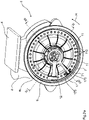
- the separating device 5, shown in Figure 2a includes a housing 6 for providing the supplied granular material G. Inside the housing 6 is a separating element 7 that can be driven in rotation about an axis of rotation D and is in particular at least partially rotationally symmetrical.
- the separating element 7 is at least partially designed as a circular disk and is set up to at least partially separate the granular material G that can be provided in the housing 6 .
- the separating element 7 can also be configured at least partially in the manner of a drum or cylinder.
- the separation device 5 shown is also designed as a positive pressure separation, with a negative pressure separation or other type of separation also being conceivable as an alternative.
- the housing 6 is divided into at least a first area and a second area by means of the at least one separating element 7 .
- Air can be supplied to the separating device 5 , in particular to the housing 6 , by means of a blower (not shown), which is coupled to the housing 6 in a fluid-conducting manner via a compressed air line 8 .
- the subdivision of the housing 6 is implemented via the separating element 7 in such a way that a pressure difference can thus be generated between the at least one first and second region.
- the separating element 7 has a plurality of grain receiving recesses 11 which are arranged at regular intervals from one another and are suitable for entraining at least one grain of the grainy material G provided in the housing 6, as shown in FIG Fig.2a to Fig.3 are shown.
- the grain receiving recesses 11 are arranged along a diameter or a radius Ri starting from an axis of rotation D in the area of an outer disk circumference.
- the grain receiving recesses 11 are arranged on the circumference of the separating element 7 .
- the first area and second area of the housing 6 are spatially connected to one another via the through-hole-like grain receiving recesses 11 .
- the individual grains G1 of the granular material G are due to the pressure difference, in particular one resulting therefrom Suction effect, can be carried along between the two areas within the grain receiving recesses 11.
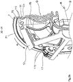
- the individual grains G1 are transported here on a front side 70 of the separating element 7 in a direction of rotation R to a cover element 12 .
- the cover element 12 is arranged on a side facing the rear side 71 of the separating element 7 .
- the cover element 12 is also set up to temporarily prevent the pressure difference, in particular locally in the area of the cover element 12, by at least partially covering at least one grain receiving recess 11. Due to the suppressed pressure difference, at least one grain G1 entrained by the separating element 7 is released for detachment in the area of the cover element 12 .
- the grain G1 released by the cover element 12 is thus transferred to a seed depositing device 13 at a defined position.
- the seed placement device 13 comprises furrow opening elements 14 designed as disc coulters, depth control elements 15 and devices 16 for closing a furrow.
- At least one ejector element 17, which can be driven by the at least one separating element 7, is arranged within the housing 6 and has a plurality of ejector elements 170, in particular distributed around the circumference.
- the ejection element 17 is arranged on the rear side 71 of the separating element 7 and behind the cover element 12 in the direction of rotation R.
- the ejection element 17 is set up by means of the ejection elements 170 to at least partially engage in the grain receiving recesses 11 and thus to clean the grain receiving recesses 11 of blockages and/or dirt.
- Firmly seated dirt, grains G1 or other deposits within the grain receiving recesses 11 are loosened by being pushed out with the ejection elements 170 .
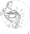
- drive sinks 110 that can be brought into engagement with the ejecting elements 170 are provided on the separating element 7 between the grain receiving recesses 11 educated.
- at least one drive sink 110 for large sowing rates or several drive sinks 110 for small sowing rates can be arranged between at least two spaced-apart grain receiving recesses 11.
- the drive sinks 110 and the grain receiving recesses 11 are arranged at a regular distance from one another and along a common diameter or radius Ri.
- the spacing of the drive sinks 110 from one another and from the respective adjacent grain receiving recesses 11 corresponds at least approximately to a division of the ejection elements 170 on the ejection element 17.
- the ejection element 17 can thus engage alternately in the drive sinks 110 and grain receiving recesses 11 during operation by means of the ejection elements 170.
- the dimensions of the drive sinks 110 correspond at least essentially to those of the grain receiving recesses 11, the drive sinks 110 being designed as blind holes and not breaking through the separating element 7.
- the drive sinks 110 can also be designed as through-holes, with the larger of the hole being smaller, in particular by a multiple, than that of the grain receiving recesses 11.
- the drive sinks 110 in particular starting from the rear side 71 of the separating element 7, are at least partially conical, in particular in the form of a truncated cone.
- the depth of the drive sinks 110 at least essentially exceeds the length of an engaging part or section of the ejection elements 170.
- the drive in particular a force, is thus transmitted at least almost exclusively via the side or conical surfaces of the drive sinks 110 from the separating element 7 to the Ejection elements 170 and thus on the Ejection organ 17 transferred.
- the depth can also be designed to correspond to and/or be at least almost equal to the length of the engaging part or section of the ejection elements 170 .
Landscapes
- Life Sciences & Earth Sciences (AREA)
- Soil Sciences (AREA)
- Environmental Sciences (AREA)
- Fertilizing (AREA)
Applications Claiming Priority (1)
| Application Number | Priority Date | Filing Date | Title |
|---|---|---|---|
| DE102020131964.9A DE102020131964A1 (de) | 2020-12-02 | 2020-12-02 | Landwirtschaftliche Vereinzelungsvorrichtung zur Vereinzelung von körnigem Material |
Publications (2)
| Publication Number | Publication Date |
|---|---|
| EP4008169A1 true EP4008169A1 (fr) | 2022-06-08 |
| EP4008169B1 EP4008169B1 (fr) | 2025-10-22 |
Family
ID=78851155
Family Applications (1)
| Application Number | Title | Priority Date | Filing Date |
|---|---|---|---|
| EP21401049.8A Active EP4008169B1 (fr) | 2020-12-02 | 2021-11-29 | Dispositif agricole de séparation destiné au séparation de la matière granulaire |
Country Status (4)
| Country | Link |
|---|---|
| EP (1) | EP4008169B1 (fr) |
| DE (1) | DE102020131964A1 (fr) |
| DK (1) | DK4008169T3 (fr) |
| PL (1) | PL4008169T3 (fr) |
Citations (4)
| Publication number | Priority date | Publication date | Assignee | Title |
|---|---|---|---|---|
| US9338939B1 (en) * | 2015-01-29 | 2016-05-17 | Rrv Canola Disk Inc. | Seed disk for planting canola with a vacuum meter planter |
| EP3266299A1 (fr) | 2016-07-06 | 2018-01-10 | PÖTTINGER Landtechnik GmbH | Presse à balles |
| EP3235360B1 (fr) | 2011-03-22 | 2019-09-25 | Precision Planting LLC | Dispositif de dosage de graines |
| EP3735813A1 (fr) * | 2019-05-10 | 2020-11-11 | Deere & Company | Ensemble doseur de graines et élément de mesure pour petites graines |
-
2020
- 2020-12-02 DE DE102020131964.9A patent/DE102020131964A1/de active Pending
-
2021
- 2021-11-29 PL PL21401049.8T patent/PL4008169T3/pl unknown
- 2021-11-29 EP EP21401049.8A patent/EP4008169B1/fr active Active
- 2021-11-29 DK DK21401049.8T patent/DK4008169T3/da active
Patent Citations (4)
| Publication number | Priority date | Publication date | Assignee | Title |
|---|---|---|---|---|
| EP3235360B1 (fr) | 2011-03-22 | 2019-09-25 | Precision Planting LLC | Dispositif de dosage de graines |
| US9338939B1 (en) * | 2015-01-29 | 2016-05-17 | Rrv Canola Disk Inc. | Seed disk for planting canola with a vacuum meter planter |
| EP3266299A1 (fr) | 2016-07-06 | 2018-01-10 | PÖTTINGER Landtechnik GmbH | Presse à balles |
| EP3735813A1 (fr) * | 2019-05-10 | 2020-11-11 | Deere & Company | Ensemble doseur de graines et élément de mesure pour petites graines |
Also Published As
| Publication number | Publication date |
|---|---|
| DE102020131964A1 (de) | 2022-06-02 |
| DK4008169T3 (en) | 2025-12-15 |
| PL4008169T3 (pl) | 2026-02-16 |
| EP4008169B1 (fr) | 2025-10-22 |
Similar Documents
| Publication | Publication Date | Title |
|---|---|---|
| DE2261344C3 (de) | Vorrichtung zum Ablegen von körnigem Saatgut im Erdreich in Verbindung mit Einzelkornsämaschinen | |
| DE102013100118B3 (de) | Abstreifeinrichtung, Säherz und Einzelkornsämaschine | |
| DE3419951C2 (de) | Vorrichtung zum Vereinzeln und Verteilen von körnigem Gut, insbesondere an Einzelkornsämaschinen | |
| DE8108744U1 (de) | Sävorrichtung mit pneumatischem Saatgutejektor, insbesondere für Gemüsekulturen | |
| DE2610223A1 (de) | Pneumatische einzelkornsaemaschine | |
| EP3440908B1 (fr) | Dispositif de séparation pour matériau granulaire avec ensemble de conversion | |
| DE3530514C2 (fr) | ||
| DE1949926C3 (de) | Drillmaschine oder Düngerstreuer mit Dosiervorrichtungen | |
| DE102020002762A1 (de) | Dosiervorrichtung für eine landwirtschaftliche Maschine | |
| EP2183952A1 (fr) | Elément doseur d'un semoir et semoir monograine | |
| EP4008169B1 (fr) | Dispositif agricole de séparation destiné au séparation de la matière granulaire | |
| EP2939511B1 (fr) | Unité doseuse et semeuse mono-graine | |
| DE102013100113B4 (de) | Abstreifer, Abstreifeinrichtung, Säherz | |
| EP2974583B9 (fr) | Unité doseuse et semeuse mono-graine | |
| WO2020178438A1 (fr) | Dispositif pour un semoir agricole, procédé de séparation de graines dans un dispositif pour un semoir agricole ainsi que semoir agricole | |
| DE102008007614A1 (de) | Einzelkornsämaschine | |
| DE2008164A1 (de) | Bodenbearbeitungsmaschine mit umlaufendem Kultivator | |
| EP3496984B1 (fr) | Tuyère de sablage pour un système d'épandage de sable d'un véhicule ferroviaire, système d'épandage de sable ainsi que véhicule ferroviaire | |
| DE102005038155A1 (de) | Pneumatische Einzelkornsämaschine | |
| EP2117290B1 (fr) | Semoir monograine pneumatique | |
| DE202019105991U1 (de) | Vorrichtung zur Vereinzelung von kornförmigem Saatgut und Einzelkornsämaschine | |
| EP4447750A1 (fr) | Dispositif d'alimentation de faisceaux de soies pour la production de produits à base de soies, et machine de production de matériaux à base de soies | |
| DE202021105513U1 (de) | Durchführung, Behälterabschnitt und einen solchen Behälterabschnitt aufweisender Behälter | |
| EP1752029A1 (fr) | Semoir pneumatique monograine | |
| DE102020112177A1 (de) | Vereinzelungseinrichtung zum Vereinzeln von Saatkörnern |
Legal Events
| Date | Code | Title | Description |
|---|---|---|---|
| PUAI | Public reference made under article 153(3) epc to a published international application that has entered the european phase |
Free format text: ORIGINAL CODE: 0009012 |
|
| STAA | Information on the status of an ep patent application or granted ep patent |
Free format text: STATUS: THE APPLICATION HAS BEEN PUBLISHED |
|
| AK | Designated contracting states |
Kind code of ref document: A1 Designated state(s): AL AT BE BG CH CY CZ DE DK EE ES FI FR GB GR HR HU IE IS IT LI LT LU LV MC MK MT NL NO PL PT RO RS SE SI SK SM TR |
|
| STAA | Information on the status of an ep patent application or granted ep patent |
Free format text: STATUS: REQUEST FOR EXAMINATION WAS MADE |
|
| 17P | Request for examination filed |
Effective date: 20221101 |
|
| RBV | Designated contracting states (corrected) |
Designated state(s): AL AT BE BG CH CY CZ DE DK EE ES FI FR GB GR HR HU IE IS IT LI LT LU LV MC MK MT NL NO PL PT RO RS SE SI SK SM TR |
|
| P01 | Opt-out of the competence of the unified patent court (upc) registered |
Effective date: 20230523 |
|
| GRAP | Despatch of communication of intention to grant a patent |
Free format text: ORIGINAL CODE: EPIDOSNIGR1 |
|
| STAA | Information on the status of an ep patent application or granted ep patent |
Free format text: STATUS: GRANT OF PATENT IS INTENDED |
|
| RIC1 | Information provided on ipc code assigned before grant |
Ipc: A01C 7/04 20060101AFI20250618BHEP |
|
| INTG | Intention to grant announced |
Effective date: 20250627 |
|
| GRAS | Grant fee paid |
Free format text: ORIGINAL CODE: EPIDOSNIGR3 |
|
| GRAA | (expected) grant |
Free format text: ORIGINAL CODE: 0009210 |
|
| STAA | Information on the status of an ep patent application or granted ep patent |
Free format text: STATUS: THE PATENT HAS BEEN GRANTED |
|
| AK | Designated contracting states |
Kind code of ref document: B1 Designated state(s): AL AT BE BG CH CY CZ DE DK EE ES FI FR GB GR HR HU IE IS IT LI LT LU LV MC MK MT NL NO PL PT RO RS SE SI SK SM TR |
|
| REG | Reference to a national code |
Ref country code: CH Ref legal event code: F10 Free format text: ST27 STATUS EVENT CODE: U-0-0-F10-F00 (AS PROVIDED BY THE NATIONAL OFFICE) Effective date: 20251022 Ref country code: GB Ref legal event code: FG4D Free format text: NOT ENGLISH |
|
| REG | Reference to a national code |
Ref country code: DE Ref legal event code: R096 Ref document number: 502021009014 Country of ref document: DE |
|
| REG | Reference to a national code |
Ref country code: IE Ref legal event code: FG4D Free format text: LANGUAGE OF EP DOCUMENT: GERMAN |
|
| REG | Reference to a national code |
Ref country code: SE Ref legal event code: TRGR |
|
| REG | Reference to a national code |
Ref country code: DK Ref legal event code: T3 Effective date: 20251211 |
|
| PGFP | Annual fee paid to national office [announced via postgrant information from national office to epo] |
Ref country code: DE Payment date: 20251014 Year of fee payment: 5 |
|
| PGFP | Annual fee paid to national office [announced via postgrant information from national office to epo] |
Ref country code: AT Payment date: 20260113 Year of fee payment: 5 |
|
| PGFP | Annual fee paid to national office [announced via postgrant information from national office to epo] |
Ref country code: DK Payment date: 20251219 Year of fee payment: 5 |
|
| PGFP | Annual fee paid to national office [announced via postgrant information from national office to epo] |
Ref country code: FR Payment date: 20251023 Year of fee payment: 5 |
|
| PGFP | Annual fee paid to national office [announced via postgrant information from national office to epo] |
Ref country code: SE Payment date: 20251028 Year of fee payment: 5 |
|
| REG | Reference to a national code |
Ref country code: NL Ref legal event code: MP Effective date: 20251022 |
|
| PG25 | Lapsed in a contracting state [announced via postgrant information from national office to epo] |
Ref country code: NL Free format text: LAPSE BECAUSE OF FAILURE TO SUBMIT A TRANSLATION OF THE DESCRIPTION OR TO PAY THE FEE WITHIN THE PRESCRIBED TIME-LIMIT Effective date: 20251022 |