EP4008220B1 - Schlafkoje, insbesondere für eine fahrzeugkabine - Google Patents
Schlafkoje, insbesondere für eine fahrzeugkabine Download PDFInfo
- Publication number
- EP4008220B1 EP4008220B1 EP20211619.0A EP20211619A EP4008220B1 EP 4008220 B1 EP4008220 B1 EP 4008220B1 EP 20211619 A EP20211619 A EP 20211619A EP 4008220 B1 EP4008220 B1 EP 4008220B1
- Authority
- EP
- European Patent Office
- Prior art keywords
- bunk
- supporting members
- area
- adaptable
- moving mechanism
- Prior art date
- Legal status (The legal status is an assumption and is not a legal conclusion. Google has not performed a legal analysis and makes no representation as to the accuracy of the status listed.)
- Active
Links
Images


Classifications
-
- A—HUMAN NECESSITIES
- A47—FURNITURE; DOMESTIC ARTICLES OR APPLIANCES; COFFEE MILLS; SPICE MILLS; SUCTION CLEANERS IN GENERAL
- A47C—CHAIRS; SOFAS; BEDS
- A47C31/00—Details or accessories for chairs, beds, or the like, not provided for in other groups of this subclass, e.g. upholstery fasteners, mattress protectors, stretching devices for mattress nets
- A47C31/12—Means, e.g. measuring means, for adapting chairs, beds or mattresses to the shape or weight of persons
- A47C31/123—Means, e.g. measuring means, for adapting chairs, beds or mattresses to the shape or weight of persons for beds or mattresses
-
- B—PERFORMING OPERATIONS; TRANSPORTING
- B60—VEHICLES IN GENERAL
- B60P—VEHICLES ADAPTED FOR LOAD TRANSPORTATION OR TO TRANSPORT, TO CARRY, OR TO COMPRISE SPECIAL LOADS OR OBJECTS
- B60P3/00—Vehicles adapted to transport, to carry or to comprise special loads or objects
- B60P3/32—Vehicles adapted to transport, to carry or to comprise special loads or objects comprising living accommodation for people, e.g. caravans, camping, or like vehicles
- B60P3/36—Auxiliary arrangements; Arrangements of living accommodation; Details
- B60P3/38—Sleeping arrangements, e.g. living or sleeping accommodation on the roof of the vehicle
-
- B—PERFORMING OPERATIONS; TRANSPORTING
- B62—LAND VEHICLES FOR TRAVELLING OTHERWISE THAN ON RAILS
- B62D—MOTOR VEHICLES; TRAILERS
- B62D33/00—Superstructures for load-carrying vehicles
- B62D33/06—Drivers' cabs
- B62D33/0612—Cabins with living accommodation, especially for long distance road vehicles, i.e. sleeping, cooking, or other facilities
-
- A—HUMAN NECESSITIES
- A47—FURNITURE; DOMESTIC ARTICLES OR APPLIANCES; COFFEE MILLS; SPICE MILLS; SUCTION CLEANERS IN GENERAL
- A47C—CHAIRS; SOFAS; BEDS
- A47C17/00—Sofas; Couches; Beds
- A47C17/64—Travelling or camp beds
- A47C17/80—Travelling or camp beds adapted to be used in or connected to vehicles
-
- A—HUMAN NECESSITIES
- A47—FURNITURE; DOMESTIC ARTICLES OR APPLIANCES; COFFEE MILLS; SPICE MILLS; SUCTION CLEANERS IN GENERAL
- A47C—CHAIRS; SOFAS; BEDS
- A47C23/00—Spring mattresses with rigid frame or forming part of the bedstead, e.g. box springs; Divan bases; Slatted bed bases
- A47C23/04—Spring mattresses with rigid frame or forming part of the bedstead, e.g. box springs; Divan bases; Slatted bed bases using springs in compression, e.g. coiled
- A47C23/043—Spring mattresses with rigid frame or forming part of the bedstead, e.g. box springs; Divan bases; Slatted bed bases using springs in compression, e.g. coiled using wound springs
- A47C23/0435—Spring mattresses with rigid frame or forming part of the bedstead, e.g. box springs; Divan bases; Slatted bed bases using springs in compression, e.g. coiled using wound springs of adjustable resilience
-
- A—HUMAN NECESSITIES
- A47—FURNITURE; DOMESTIC ARTICLES OR APPLIANCES; COFFEE MILLS; SPICE MILLS; SUCTION CLEANERS IN GENERAL
- A47C—CHAIRS; SOFAS; BEDS
- A47C27/00—Spring, stuffed or fluid mattresses or cushions specially adapted for chairs, beds or sofas
- A47C27/04—Spring, stuffed or fluid mattresses or cushions specially adapted for chairs, beds or sofas with spring inlays
- A47C27/06—Spring inlays or spring units therefor
- A47C27/061—Spring inlays or spring units therefor of adjustable resiliency
-
- A—HUMAN NECESSITIES
- A47—FURNITURE; DOMESTIC ARTICLES OR APPLIANCES; COFFEE MILLS; SPICE MILLS; SUCTION CLEANERS IN GENERAL
- A47C—CHAIRS; SOFAS; BEDS
- A47C27/00—Spring, stuffed or fluid mattresses or cushions specially adapted for chairs, beds or sofas
- A47C27/04—Spring, stuffed or fluid mattresses or cushions specially adapted for chairs, beds or sofas with spring inlays
- A47C27/06—Spring inlays or spring units therefor
- A47C27/063—Spring inlays or spring units therefor wrapped or otherwise protected
- A47C27/064—Pocketed springs
-
- B—PERFORMING OPERATIONS; TRANSPORTING
- B60—VEHICLES IN GENERAL
- B60N—SEATS SPECIALLY ADAPTED FOR VEHICLES; VEHICLE PASSENGER ACCOMMODATION NOT OTHERWISE PROVIDED FOR
- B60N3/00—Arrangements or adaptations of other passenger fittings, not otherwise provided for
- B60N3/008—Arrangements or adaptations of other passenger fittings, not otherwise provided for of beds
-
- A—HUMAN NECESSITIES
- A47—FURNITURE; DOMESTIC ARTICLES OR APPLIANCES; COFFEE MILLS; SPICE MILLS; SUCTION CLEANERS IN GENERAL
- A47C—CHAIRS; SOFAS; BEDS
- A47C23/00—Spring mattresses with rigid frame or forming part of the bedstead, e.g. box springs; Divan bases; Slatted bed bases
- A47C23/04—Spring mattresses with rigid frame or forming part of the bedstead, e.g. box springs; Divan bases; Slatted bed bases using springs in compression, e.g. coiled
- A47C23/043—Spring mattresses with rigid frame or forming part of the bedstead, e.g. box springs; Divan bases; Slatted bed bases using springs in compression, e.g. coiled using wound springs
-
- A—HUMAN NECESSITIES
- A47—FURNITURE; DOMESTIC ARTICLES OR APPLIANCES; COFFEE MILLS; SPICE MILLS; SUCTION CLEANERS IN GENERAL
- A47C—CHAIRS; SOFAS; BEDS
- A47C31/00—Details or accessories for chairs, beds, or the like, not provided for in other groups of this subclass, e.g. upholstery fasteners, mattress protectors, stretching devices for mattress nets
- A47C31/12—Means, e.g. measuring means, for adapting chairs, beds or mattresses to the shape or weight of persons
Definitions
- the invention relates to a bunk.
- the invention can be applied in heavy-duty vehicles, such as trucks, having a cabin equipped with such a bunk.
- the vehicle can have a cabin equipped with a bunk.
- the pressure distribution on the body changes depending on the user's position on the bunk. For example, this pressure distribution changes whether the user lies on his back or on his side - in which position there are higher constraints in the shoulder and pelvis areas. As a result, the user's comfort may significantly change during the night, depending on his position on the bunk.
- EP 2 745 745 discloses a bed with automatic adjustable properties.
- WO 2006/100093 discloses an adjustable mattress.
- An object of the invention is to provide a bunk having an increased comfort for the user.
- the invention relates to a bunk, in particular for a vehicle cabin, as set forth in claim 1.
- the bunk can provide a real-time adaptation of the local firmness in one or several areas of the bunk, to better suit the current needs of the bunk's user and constantly adjust during the user's rest or night.
- the bunk can dynamically adapt to the user's position on the bunk, i.e. to the pressure distribution on the bunk.
- the "density" of the supporting members means the number of supporting members per area unit of the base plate.
- the overall density in an adaptable area of the bunk can remain unchanged, while the positions of the supporting members may vary in said adaptable area, resulting in density changing locally in one or several sub-area(s) of said adaptable area.
- the pressure sensors are part of the upper layer.
- the pressure sensors may be embedded in said upper layer.
- the pressure sensors can be embedded in a sheet of the upper layer, for example by being assembled with other components to form such a sheet.
- Said sheet including the pressure sensors can be located adjacent one or several other sheets of the upper layer; for example, it can be sandwiched between two sheets of the upper layer.
- the pressure sensors can be located and secured between two sheets of the upper layer, without being part of a specific sheet.
- the pressure sensors may be located over the whole bunk surface, or only in the or each adaptable area.
- the pressure sensors may comprise a pressure-sensitive wire.
- This wire can be assembled with yarns (such as textile yarns), for example by weaving or knitting, to form at least part of the upper layer.
- this wire can be fastened between two sheets, such as two sheets of textile, to form at least part of the upper layer.
- the pressure-sensitive wire can form a wavy line which extends over the whole adaptable area, or over the whole bunk upper face.
- the pressure sensors may comprise a pressure-sensitive thin film fastened to at least one sheet, or between two sheets of the upper layer.
- the pressure sensors may comprise distinct sensors, preferably arranged according to an array. These distinct sensors can be embedded in the upper layer, for example between two sheets of the upper layer.
- the bunk comprises a sliding layer arranged between the supporting members and the upper layer, at least in the adaptable area.
- the sliding layer can be arranged directly on top of the supporting members, or on an upper face of an envelope which houses the supporting members, or under the upper layer with the sliding layer facing downwards, i.e. towards the supporting members.
- Such a sliding layer helps to make the movement of the supporting members easier and smoother despite the presence of a user laying on the bunk.
- the supporting member to be moved can first be vertically compressed, then moved (which is easier as the body pressure is exerted on the surrounding supporting members but not - or to a much lesser extent - on the compressed supporting member), and finally released.
- the bunk may comprise at least two adaptable areas.
- the bunk may comprise one first adaptable area, which corresponds to a user's shoulder area.
- Said first adaptable area may be defined between two lines which, from the transverse end of the bunk located on the user's head side, are located at a distance of around 20% and around 30%, respectively, of the bunk length.
- the bunk may also comprise one second adaptable area which corresponds to a user's pelvis area.
- Said second adaptable area may be defined between two lines which, from the transverse end of the bunk located on the user's head side, are located at a distance of around 40% and around 60%, respectively, of the bunk length.
- the second adaptable area is useful in particular for adapting the pressure exerted at the level or in the vicinity of the user's hips.
- the first and second adaptable areas can be separate; then, controlling the moving mechanism can be made independently in each adaptable area.
- the bunk can include one single adaptable area including these first and second adaptable areas as well as a possible intermediate area in between; then, for example, the single adaptable area can correspond to a user's torso and pelvis area.
- the supporting members outside the adaptable area(s) can preferably be stationary relative to the base plate, at least along a direction parallel to the base plate.
- the bunk may have a substantially rectangular shape defining a longitudinal direction and a transverse direction.
- the bunk may comprise at least one row of supporting members which extends transversally, the supporting members of said row being movable together, typically as a whole, by the moving mechanism along the longitudinal direction.
- the supporting members of the row can thus be moved closer to or apart from the adjacent supporting members, to locally change the density of supporting members.
- Said row of supporting members can extend transversally over the whole bunk width, or not.
- the bunk in an adaptable area, may comprise at least one column of supporting members which extends longitudinally, the supporting members of said column being movable together, typically as a whole, by the moving mechanism along the transverse direction.
- the movements along the longitudinal and transverse directions can be combined. Alternatively, only one movement can be possible; then, it is preferably along the longitudinal direction.
- the moving mechanism can comprise a motor and an actuator operated by the motor and capable of moving the supporting members.
- the actuator can be a pneumatic member.
- it can be a cable forming a loop.
- the loop has a fixed length, and the cable turns so that one point of the cable moves along said loop; the supporting members can be secured to a point of the cable, for example by means of a slider secured to the cable and engaged in a rail; then, moving the cable along the loop causes the movement of the supporting members.
- the cable can be wounded such that the length of the loop decreases; this causes the movement of the supporting members, for example through a pulling movement exerted by the cable on the supporting members or on a member fastened to the supporting members.
- Two adjacent supporting members in the adaptable area are linked by an elastic connection which in a neutral state is pre-tensioned and further extendable, such that these adjacent supporting members can be moved relative to one another when an appropriate action is applied by the moving mechanism on the supporting members, and can elastically return to the neutral state when said action is released.
- Releasing said action can consist stopping any action, or in applying a reverse action, so that the supporting members can go back to the neutral state.
- Two adjacent supporting members in the adaptable area are linked by a non-extendable connection which allows transmitting the motion of one of said supporting members, caused by the moving mechanism, to the other one of said supporting members.
- the non-extendable connection can be active only above a predetermined distance between said adjacent supporting members. In concrete terms, the non-extendable connection is first in a flexed configuration (thus being inactive for motion transmission), then fully extended (thus being able to transmit motion).
- Both an elastic connection and a non-extendable connection are provided between two adjacent supporting members.
- At least one supporting member may comprise a plurality of supporting elements, such as four springs, which are rigidly connected to one another and housed in a pouch.
- the bunk may further comprise at least one lifting mechanism such as a cylinder, which is arranged under one or several supporting members to vertically compress it / them, so as to further allow locally changing the bunk firmness.
- at least one lifting mechanism such as a cylinder, which is arranged under one or several supporting members to vertically compress it / them, so as to further allow locally changing the bunk firmness.
- the invention also relates to a vehicle, such as an industrial vehicle comprising a cabin, the vehicle comprising a bunk as previously described.
- the invention further relates to a method for dynamically changing the firmness of a bunk in at least one adaptable area of the bunk, the method being defined in claim 12.
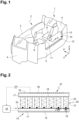
- FIG. 1 partially shows a vehicle 1 which can be an industrial vehicle, such as a truck.
- vehicle 1 comprises a cabin 2 having a front wall 3, two side walls 4, and a rear wall 5, which form a driver compartment.
- the cabin 1 also comprises at least one seat 6 for the driver and possibly one additional seat 6 for a possible passenger.
- the vehicle 1 further comprises a bunk 10 for a user 40, typically the driver, to have some rest or to sleep.
- the bunk 10 is located in the cabin, typically behind the seats 6, i.e. between these seats 6 and the rear wall 5.
- the bunk 10 is arranged horizontally and has a substantially rectangular shape.
- Direction X is defined as the longitudinal direction of the bunk 10, and corresponds to the transverse direction Y' of the vehicle 1.
- Direction Y is defined as the transverse direction of the bunk 10, and corresponds to the longitudinal direction X' of the vehicle 1.
- the bunk 10 preferably has fixed dimensions. It has two opposite longitudinal edges 11, 12 and two opposite transverse edges, namely one transverse edge 13 near the user's head, and one transverse edge 14 near the user's feet. It has to be noted that the positions of transverse edges 13, 14 in the drawings are only a possible configuration, bearing in mind that the user 40 can be in a reverse position (i.e. the feet near edge 13 and the head near edge 14).
- the bunk 10 comprises a base plate 15 which is substantially horizontal and which is has a mechanical strength high enough to bear a user's weight.
- the base plate 15 may be secured to the cabin 2, at least in an active position.
- the base plate 15 may be movable relative to the cabin 2 between said active position, to allow the user 40 to rest, and an inactive position, in order to free up space when the bunk is not used.
- the bunk 10 also comprises an upper layer 16 on which the user 40 can lie down.
- the bunk 10 further comprises a plurality of supporting members 20 which are arranged between the base plate 15 and the upper layer 16, spaced apart from one another, according to an array, substantially over the whole surface of the bunk 10.
- Each supporting member 20 extends vertically, and is vertically compressible. It may comprise at least one spring 21 preferably housed in a pocket 22.
- the supporting members are illustrated as being regularly spaced apart from one another, this should not be considered as limitative.
- a comfort layer 17, such as a foam layer, may be provided between the base plate 15 and the supporting members 20, and/or between the supporting members 20 and the upper layer 16.
- the bunk 10 comprises a plurality of pressure sensors 30 which are part of the upper layer 16, and which are arranged in at least one area of the bunk 10 called adaptable area 37.
- each area can extend from one longitudinal edge 11 to the other 12, and can correspond to a portion of the body when the user 40 is lying on the bunk 10.
- the transverse edge 13 of the bunk 10 located near the user's head to the transverse edge 14 of the bunk 10 located near the user's feet, there may be defined:
- the distance of the transverse lines from the transverse edge 13, expressed as a percentage of the bunk length can be in the following ranges:
- One or several of these areas A1-A5, or a portion of thereof, can be "adaptable area(s) 37", that is to say areas in which the bunk firmness can be adapted. It should be noted that there may be defined more areas in the bunk, or on the contrary less areas, depending on the requirements in terms of adaptation capacity of the bunk firmness.
- a moving mechanism 50 is connected to at least some of the supporting members 20 located in the adaptable area 37, and is configured to move said supporting members 20 with respect to and parallel to the base plate 15.
- the moving mechanism 50 is very schematically depicted as an elongated member linked to each of the supporting members 20, the link being schematically represented as a black dot.
- a control unit 35 is connected to the pressure sensors 30 and to the moving mechanism 50.
- the control unit 35 is configured to cause the moving mechanism 50 to automatically and dynamically move the supporting members 20 in the adaptable area 37, as a function of the current pressure data provided by the pressure sensors 30.
- the density of the supporting members 20 can be locally changed, in order to provide a locally variable bunk firmness.
- the invention provides a method for dynamically changing the firmness of the bunk 10 in at least one adaptable area 37 of the bunk 10.
- the current pressure data P measured in the upper layer 16 by the pressure sensors 30 is received by the control unit 35.
- the control unit 35 automatically and dynamically controls the moving mechanism 50 to move at least some of the supporting members 20 located in the adaptable area 37 with respect to and parallel to the base plate 15. This results in locally changing the density of the supporting members 20, and ultimately improving the user's comfort.
- the bunk 10 may comprise a sliding layer 18 arranged between the supporting members 20 and the upper layer 16, at least in the adaptable area 37.
- the bunk 10 may further comprise at least one lifting mechanism 19 such as a cylinder, arranged under one or several supporting members to vertically compress it / them. This allows further locally changing the bunk firmness.
- the lifting mechanism 19 may be controlled by the control unit 35 as a function of the current pressure data provided by the pressure sensors 30.
- the pressure sensors 30 are in the form of a pressure-sensitive wire 30a.
- the wire 30a may be assembled with yarns 36 (which are schematically and partially illustrated in figure 3 ), for example by weaving or knitting, to form the upper layer 16 or one sheet including in the upper layer 16.
- the pressure-sensitive wire 30a forms a wavy line having main portions arranged transversely, and which extends over the whole bunk upper face.
- a wavy line having main portions arranged longitudinally a pressure-sensitive wire 30a having a different arrangement (zig zag line, non-continuous line, etc.); a pressure-sensitive wire 30a extending only in one or several adaptable areas 37 of the bunk not covering the whole bunk surface.
- the pressure sensors 30 comprise distinct sensors 30b.
- the sensors 30b can be arranged according to an array, for example according to a rectangular array.
- the sensors 30b may be spaced apart from one another by a distance of around 50 mm.
- the sensors 30b may be sandwiched between two sheets 16a, 16b of the upper layer 16. They can be secured, for example by means of an adhesive, to one of said sheets and then covered by the other sheet.
- the pressure sensors 30 do not cover the whole bunk surface, although this could be a possible option.
- the pressure sensors 30 are located only in adaptable areas 37 of the bunk 10, or possibly only in a sub-area of said adaptable areas 37.
- the adaptable areas 37a, 37b are spaced apart from one another but could alternatively be adjacent.
- the adaptable areas 37a, 37b extend from one longitudinal edge 11 to the other longitudinal edge 12 but could alternatively extend only over part of the bunk width, for example in a central portion thereof.
- FIG. 5 to 8 An embodiment of a bunk according to the invention is shown in figures 5 to 8 . In these figures are only shown the supporting members 20, the moving mechanism 50 and the control unit 35.
- the pressure sensors 30 can be conform to the previous description with reference to either figure 3 or 4 .
- the supporting members 20 may be arranged according to an array forming rows and columns, over the whole surface of the bunk 10.
- the bunk 10 comprises the previously described first and second adaptable areas 37a, 37b, although other variants could be envisaged.
- the bunk comprises at least one row 38 of supporting members 20 which extends transversally, preferably over the whole bunk width.
- the first adaptable area 37a may comprise three rows 38 of supporting members 20, while the second adaptable area 37b may comprise five rows 38 of supporting members 20.
- Such an implementation is not limitative.
- each row 38 of supporting members 20 may comprise, at each end, a slider 51 engaged in a rail 52.
- the rails 52 remain in a fixed position relative to the base plate 15, while the sliders 51 can move longitudinally in the rails 52.
- the sliders 51 may be moved by means of a cable (not shown) secured to said sliders 51 and driven by the control unit 35, depending on the current pressure data P provided by the pressure sensors 30.
- each row 38 can be moved independently of the other rows 38, which may require one actuator (such as a cable) dedicated to the operation of one and each row 38.
- the rows 38 of the first adaptable area 37a may be moved independently of the rows 38 of the second adaptable area 37b.
- the supporting members 20 of one row 38 can be secured to one another; for example, two adjacent supporting members 20 may be secured through a link between their pockets 22, or the supporting members 20 can be mounted on a common transverse board which is movable by the moving mechanism 50.
- the supporting members 20 outside the adaptable areas 37a, 37b are preferably motionless relative to the bunk base plate 15.
- the supporting members 20 are in a first configuration, namely arranged according to a uniform rectangular array, over the whole surface of the bunk 10. The bunk firmness is then uniform over the whole bunk surface. This may be comfortable for a user 40 lying on the back ( figure 6 ). As can be seen in figure 6 , the supporting members 20 may be dissimilarly vertically compressed, depending on the body pressure to which each supporting member is subjected and/or on the controlled action of the lifting mechanism 19.
- the supporting members 20 are in a second configuration. This may result from the user 40 having changed his position to lie on his side ( figure 8 ). Indeed, higher pressure is then exerted by the user's body in the shoulder and pelvis areas, i.e. in areas A2 and A4, corresponding to the first and second adaptable areas 37a, 37b of the bunk 10.
- the current pressure data P corresponding to the higher pressure measured by the sensors 30 is received by the control unit 35 which controls the moving mechanism 50 in order to adapt the bunk firmness in the adaptable areas 37a, 37b.
- the bunk 10 is designed so that a higher body pressure results in a local higher bunk firmness.
- an opposite solution could be envisaged.
- each adaptable area 37a, 37b the supporting members 20 have been moved closer to one another, as shown in figure 8 , which provides a higher local firmness.
- the supporting members 20 are spaced from one another by a distance which is smaller than the distance between adjacent supporting members 20 in other areas of the bunk 10.
- the supporting members 20 may further be dissimilarly vertically compressed depending on the body pressure to which each supporting member is subjected and/or on the controlled action of the lifting mechanism 19.
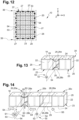
- FIGS 9 to 17 partially show a bunk 10 according to another embodiment of the invention.
- the pressure sensors 30 can be conform to the previous description with reference to either figure 3 or 4 .
- some or all supporting members 20 may be as shown in figure 10 .
- a supporting member 20 comprises a plurality of supporting elements 23, here four springs 21 which are preferably individually housed in a pocket 22.
- the supporting elements 23 are arranged at the corners of a square or rectangle, and are rigidly connected to one another by a link 24 schematically illustrated in figure 10 .
- the supporting elements 23 are housed in a pouch 25.
- the upper and lower faces of the pouch 25 may be provided with a sliding layer 18 to make the movement of the supporting members 20 easier.
- the supporting members 20 in the adaptable area(s) 37 could be as shown in figure 2 , i.e. made of a single compressible element such as a spring.
- the supporting members 20 outside the adaptable area(s) 37 are preferably as shown in figure 2 . They may be arranged according to an array forming rows and columns, such as a uniform rectangular array. They are preferably motionless relative to the bunk base plate 15.
- the bunk 10 comprises two adaptable areas 37 which do not extend over the whole bunk width, a column 39 of stationary supporting members 20 being provided adjacent near each longitudinal edge 11, 12.
- the first adaptable area 37a is part of the above-mentioned area A2, i.e. corresponds to a user's shoulder area; the second adaptable area 37b is part of the above-mentioned area A4, i.e. corresponds to a user's pelvis area.
- the supporting members 20 are arranged according to an array forming rows and columns, such as a uniform rectangular array, and are preferably housed in an envelope 26.
- each adaptable area 37 may include an array of 4 rows x 6 columns of supporting members 20 according to figure 10 .
- Each envelope 26 is stationary relative to the base plate 15 of the bunk.
- the walls of the envelope 26 can be secured to the surrounding supporting members 20 outside the adaptable areas 37, or to a stationary member of the bunk 10 such as the base plate 15.
- the supporting members 20 located inside the envelope 26 and adjacent the envelope peripheral walls are secured to the envelope 26, as schematically illustrated by dots 27 in figure 12 .
- the elastic connection 28 can comprise an upper sheet 28a extending from the pouch upper wall, and a lower sheet 28b extending from the pouch lower wall.
- the non-extendable connection 29 may comprise at least one strand having one end secured to one supporting member 20 and an opposite end secured to an adjacent supporting member 20. There may be provided a strand on both sides of the upper sheet 28a and a strand on both sides of the lower sheet 28b.
- each elastic connection 28 is pre-tensioned and further extendable, and each non-extendable connection 29 is loose and not taut.
- the moving mechanism 50 comprises several sets, each set having a motor 53 and an actuator which is operated by the motor 53 so as to be capable of moving the supporting members 20.
- the motor 53 can be a stepper motor. All sets are preferably housed in the envelope 26.
- the actuator comprises a cable 54 which forms a loop. More specifically, one of such sets can be arranged in each gap between two adjacent rows of supporting members 20 as well as in each gap between two adjacent columns of supporting members 20 in the envelope 26.
- the corresponding cable 54 then extends substantially in a vertical transverse plane, respectively in a vertical longitudinal plane.
- the cable 54 forms a loop passing above all successive upper sheets 28a, then down near the envelope wall opposite the motor 53, and under all successive lower sheets 28b back to the motor 53.
- the rows of supporting members 20 can be moved together along the longitudinal direction X, and/or the columns of supporting members 20 can be moved together along the transverse direction Y, so as to locally change the bunk firmness.
- the supporting members 20 can be moved relative to one another as will now be described with reference to figure 14 .
- the control unit 35 drives the moving mechanism 50 to appropriately move the supporting members 20.
- the motor 53 runs (step S1 in figure 14 ) so that it can wind the cable 54 (step S2), possibly by a wind-up system not shown.
- the length of the loop formed by the cable 54 decreases, which causes the cable 54 to push on the upper sheet 28a and lower sheet 28b towards one another, along vertical direction Z.
- the sheets 28a, 28b are thus further extended. This continues until the cable 54 comes into contact with the non-extendable connection 29 then in a fully taut state.
- step S3 The pulling action of cable 54 on the fully taut non-extendable connection 29 (step S3) causes the first and second supporting members 20a, 20b on both sides of the non-extendable connection 29 to move closer to one another (step S4). Then, the elastic connection 28 which connects one of said supporting members 20b to a third adjacent supporting member 20c is extended until the non-extendable connection 29 between said supporting members 20b, 20c is fully taut. As long as the non-extendable connection 29 is loose, the third supporting member 20c does not move. Then, owing to said non-extendable connection 29 in fully taut state, the motion of the second supporting member 20b towards the first supporting member 20a is transmitted to the third supporting member 20c (step S5). The movement can thus be transmitted from one supporting member tot the next.
- the local density of the supporting members i.e. the number of supporting members per area unit of the base plate 15 in at least one sub-area of the envelope 26 can vary dynamically depending on the current pressure data P.
- step S'1 in figure 15 when the winding action is released, more specifically when the motor 54 turns in the opposite direction (step S'1 in figure 15 ), the length of the loop formed by the cable 53 increases (step S'2) and the non-extendable connection 29 becomes loose again (step S'3). Due to the stretched elastic connection 28, the first and second supporting members 20a, 20b elastically return towards the neutral state (step S'4). In turn, the third supporting member 20c is allowed to elastically move back to the neural position (step S'5).
- Figure 16 shows an optional feature allowing to further adapt the bunk firmness.
- the bunk 10 may further comprise at least one lifting mechanism 19 such as a cylinder, arranged under one or several supporting members 20, to vertically compress it/ them by means of a pressure board 41.
- each supporting member 20 of one adaptable area 37 is movable independently of other supporting members 20.
- each supporting member 20 has to be operated by its own moving mechanism 35, which must be independently controlled. Such an implementation allows further improving comfort for the user 40.
- the invention provides a bunk having automatically adaptive local firmness for all users, whatever their morphology (stature, weight, etc.), whatever the pressure distribution (typically whether the user lies on his back or on his side), without any specific action from the user. This ensures comfort all over the night, therefore good and efficient sleeping, and ultimately increased safety.
Landscapes
- Engineering & Computer Science (AREA)
- Transportation (AREA)
- Mechanical Engineering (AREA)
- Health & Medical Sciences (AREA)
- Public Health (AREA)
- General Health & Medical Sciences (AREA)
- Nursing (AREA)
- Chemical & Material Sciences (AREA)
- Combustion & Propulsion (AREA)
- Mattresses And Other Support Structures For Chairs And Beds (AREA)
- Measurement Of The Respiration, Hearing Ability, Form, And Blood Characteristics Of Living Organisms (AREA)
Claims (12)
- Schlafkoje (10), insbesondere für eine Fahrzeugkabine (2), umfassend:- eine Basisplatte (15);- eine obere Schicht (16);- eine Vielzahl von Stützelementen (20), die vertikal zusammendrückbar sind, wie beispielsweise Federn, wobei die Stützelemente (20) in einem Abstand zueinander in einer Anordnung im Wesentlichen über die gesamte Oberfläche der Schlafkoje (10) angeordnet sind;- eine Vielzahl von Drucksensoren (30), die Teil der oberen Schicht (16) sind und in mindestens einem Bereich der Schlafkoje (10), der als anpassbarer Bereich (37) bezeichnet wird, angeordnet sind;- einen Bewegungsmechanismus (50), der mit mindestens einigen der Stützelemente (20) verbunden ist, die sich im anpassbaren Bereich (37) befinden;- eine Steuereinheit (35), die mit den Drucksensoren (30) und dem Bewegungsmechanismus (50) verbunden ist, wobei die Steuereinheit (35) dazu konfiguriert ist, den Bewegungsmechanismus (50) dazu zu veranlassen, die Stützelemente (20) im anpassbaren Bereich (37) in Abhängigkeit der von den Drucksensoren (30) bereitgestellten aktuellen Druckdaten (P) automatisch und dynamisch zu bewegen,dadurch gekennzeichnet, dass der Bewegungsmechanismus (50) dazu konfiguriert ist, die Stützelemente (20) in Bezug auf und parallel zur Basisplatte (15) zu bewegen, um so die Dichte der Stützelemente (20), d. h. die Anzahl von Stützelementen (20), pro Flächeneinheit der Basisplatte (15) lokal zu ändern, um eine lokal variable Festigkeit der Schlafkoje bereitzustellen, und dadurch, dass zwei benachbarte Stützelemente (20) im anpassbaren Bereich (37) sowohl durch eine elastische Verbindung (28) als auch eine nicht dehnbare Verbindung (29) miteinander verbunden sind, wobei:- im neutralen Zustand die elastische Verbindung (28) vorgespannt und weiter dehnbar ist, und die nicht dehnbare Verbindung (29) locker und somit inaktiv für die Bewegungsübertragung ist;- aus dem neutralen Zustand die benachbarten Stützelemente (20) in Bezug zueinander bewegt werden können, wenn eine entsprechende Wirkung des Bewegungsmechanismus (50) auf die Stützelemente (20) angewandt wird, wobei die elastische Verbindung (28) dann weiter ausgedehnt ist und die nicht ausdehnbare Verbindung (29) dann vollständig gespannt ist, wodurch die durch den Bewegungsmechanismus (50) verursachte Bewegung eines der Stützelemente (20) auf das andere der Stützelemente (20) übertragen werden kann;- und diese benachbarten Stützelemente (20) mittels der elastischen Verbindung (28) elastisch in den neutralen Zustand zurückkehren können, wenn die Wirkung aufgehoben wird.
- Schlafkoje nach Anspruch 1, dadurch gekennzeichnet, dass die Drucksensoren einen druckempfindlichen Draht (30a) umfassen, der vorzugsweise mit Garnen (36), beispielsweise durch Weben oder Stricken, zusammengefügt ist, um mindestens einen Teil der oberen Schicht (16) zu bilden.
- Schlafkoje nach Anspruch 1 oder Anspruch 2, dadurch gekennzeichnet, dass die Drucksensoren unterschiedliche Sensoren (30b) umfassen, die vorzugsweise in einer Anordnung angeordnet sind.
- Schlafkoje nach einem der Ansprüche 1 bis 3, dadurch gekennzeichnet, dass sie mindestens im anpassbaren Bereich (37) eine Gleitschicht (18) umfasst, die zwischen den Stützelementen (20) und der oberen Schicht (16) angeordnet ist.
- Schlafkoje nach einem der Ansprüche 1 bis 4, dadurch gekennzeichnet, dass sie mindestens zwei anpassbare Bereiche (37) umfasst, wobei vorzugsweise:- ein erster anpassbarer Bereich (37a) dem Schulterbereich eines Benutzers entspricht;- und ein zweiter anpassbarer Bereich (37b) dem Beckenbereich eines Benutzers entspricht.
- Schlafkoje nach einem der Ansprüche 1 bis 5, wobei die Schlafkoje (10) eine im Wesentlichen rechteckige Form aufweist, die eine Längsrichtung (X) und eine Querrichtung (Y) definiert, dadurch gekennzeichnet, dass die Schlafkoje (10) im anpassbaren Bereich (37) mindestens eine Reihe (38) von Stützelementen (20) umfasst, die sich in Querrichtung erstreckt, wobei die Stützelemente (20) der Reihe (38) gemeinsam durch den Bewegungsmechanismus (50) entlang der Längsrichtung (X) beweglich sind.
- Schlafkoje nach einem der Ansprüche 1 bis 6, wobei die Schlafkoje (10) eine im Wesentlichen rechteckige Form aufweist, die eine Längsrichtung (X) und eine Querrichtung (Y) definiert, dadurch gekennzeichnet, dass die Schlafkoje (10) im anpassbaren Bereich (37) mindestens eine Säule aus Stützelementen (20) umfasst, die sich in Längsrichtung erstreckt, wobei die Stützelemente (20) der Säule gemeinsam durch den Bewegungsmechanismus (50) entlang der Querrichtung (Y) beweglich sind.
- Schlafkoje nach einem der Ansprüche 1 bis 7, dadurch gekennzeichnet, dass der Bewegungsmechanismus (50) einen Motor (53) und einen durch den Motor (53) betriebenen Aktuator umfasst, der die Stützelemente (20) bewegen kann, wobei der Aktuator vorzugsweise ein Kabel (54) ist, das eine Schleife bildet.
- Schlafkoje nach einem der Ansprüche 1 bis 8, dadurch gekennzeichnet, dass mindestens ein Stützelement (20) eine Vielzahl von Stützelementen (23), beispielsweise vier Federn, umfasst, die starr miteinander verbunden und in einer Tasche (25) untergebracht sind.
- Schlafkoje nach einem der Ansprüche 1 bis 9, dadurch gekennzeichnet, dass sie ferner mindestens einen Hebemechanismus (19) wie einen Zylinder umfasst, der unter einem oder mehreren Stützelementen (20) angeordnet ist, um es/sie vertikal zusammenzudrücken, um eine weitere lokale Änderung der Festigkeit der Schlafkoje zu ermöglichen.
- Fahrzeug (1), beispielsweise ein Industriefahrzeug, das eine Kabine (2) umfasst, dadurch gekennzeichnet, dass das Fahrzeug (1) eine Schlafkoje (10) nach einem der vorhergehenden Ansprüche umfasst.
- Verfahren zum dynamischen Ändern der Festigkeit einer Schlafkoje (10) nach einem der Ansprüche 1 bis 10 in mindestens einem anpassbaren Bereich (37) der Schlafkoje (10), wobei das Verfahren das Empfangen aktueller Druckdaten (P) umfasst, die in der oberen Schicht (16) in dem anpassbaren Bereich (37) gemessen werden, dadurch gekennzeichnet, dass das Verfahren ferner das automatische und dynamische Bewegen mindestens einiger der Stützelemente (20), die sich im anpassbaren Bereich (37) befinden, in Bezug auf und parallel zur Basisplatte (15) in Abhängigkeit von den aktuellen Druckdaten (P) umfasst, um die Dichte der Stützelemente (20), d. h. die Anzahl von Stützelementen (20), pro Flächeneinheit der Basisplatte (15) lokal zu ändern, wobei das Verfahren ferner das Anwenden einer entsprechenden Wirkung durch den Bewegungsmechanismus (50) auf eines der Stützelemente (20) umfasst, so dass die nicht dehnbare Verbindung (29) aus dem neutralen Zustand vollständig gespannt ist und somit das Übertragen der Bewegung des Stützelements (20) zum benachbarten Stützelement (20) ermöglicht, wobei die elastische Verbindung (28) dann weiter gedehnt ist und somit die benachbarten Stützelemente (20) in den neutralen Zustand zurückzubringen kann, wenn die Wirkung aufgehoben wird.
Priority Applications (3)
| Application Number | Priority Date | Filing Date | Title |
|---|---|---|---|
| EP20211619.0A EP4008220B1 (de) | 2020-12-03 | 2020-12-03 | Schlafkoje, insbesondere für eine fahrzeugkabine |
| US17/537,431 US12127683B2 (en) | 2020-12-03 | 2021-11-29 | Automatic adaptive comfort for bunk mattress |
| CN202111462103.6A CN114655320A (zh) | 2020-12-03 | 2021-12-02 | 铺位、包括该铺位的车辆和动态地改变铺位的硬度的方法 |
Applications Claiming Priority (1)
| Application Number | Priority Date | Filing Date | Title |
|---|---|---|---|
| EP20211619.0A EP4008220B1 (de) | 2020-12-03 | 2020-12-03 | Schlafkoje, insbesondere für eine fahrzeugkabine |
Publications (3)
| Publication Number | Publication Date |
|---|---|
| EP4008220A1 EP4008220A1 (de) | 2022-06-08 |
| EP4008220C0 EP4008220C0 (de) | 2024-03-06 |
| EP4008220B1 true EP4008220B1 (de) | 2024-03-06 |
Family
ID=73698679
Family Applications (1)
| Application Number | Title | Priority Date | Filing Date |
|---|---|---|---|
| EP20211619.0A Active EP4008220B1 (de) | 2020-12-03 | 2020-12-03 | Schlafkoje, insbesondere für eine fahrzeugkabine |
Country Status (3)
| Country | Link |
|---|---|
| US (1) | US12127683B2 (de) |
| EP (1) | EP4008220B1 (de) |
| CN (1) | CN114655320A (de) |
Cited By (1)
| Publication number | Priority date | Publication date | Assignee | Title |
|---|---|---|---|---|
| US20220175151A1 (en) * | 2020-12-03 | 2022-06-09 | Volvo Truck Corporation | Automatic adaptive comfort for bunk mattress |
Families Citing this family (2)
| Publication number | Priority date | Publication date | Assignee | Title |
|---|---|---|---|---|
| US20240298815A1 (en) * | 2023-03-06 | 2024-09-12 | Raja Singh Tuli | Body supporting system with adjustable firmness and related method and firmness adjusting device |
| ES1312613Y (es) * | 2024-07-24 | 2025-04-15 | Administracion General De La Comunidad Autonoma De Euskadi | Dispositivo para detectar la postura de una persona en una cama |
Family Cites Families (21)
| Publication number | Priority date | Publication date | Assignee | Title |
|---|---|---|---|---|
| US3340548A (en) * | 1965-10-01 | 1967-09-12 | Wortso Corp | Bedding prescription apparatus |
| JPS54126163A (en) * | 1978-03-20 | 1979-10-01 | Nippon Betsudo Seizou Kk | Internallpressureeadjusted bed |
| US4667357A (en) * | 1986-10-08 | 1987-05-26 | Fortune Richard L | Sleep unit having adjustable firmness |
| US5113539A (en) * | 1991-07-31 | 1992-05-19 | Strell Brian M | Adjustable firmness coil spring mattress with inflatable tubes |
| US5896604A (en) * | 1998-01-05 | 1999-04-27 | Mclean; Leslie Hylton | Support module |
| GB0320215D0 (en) * | 2003-08-29 | 2003-10-01 | Harrison Bedding Ltd | Spring units |
| EP1921951A1 (de) * | 2005-03-24 | 2008-05-21 | Wilhelm Ing. Schuster | 3d-multi-aktiv/passiv regulierbare matten, -matratzen und -körper sowie ein veränderbarer sensorik- und/oder wölbkörper |
| EP2878231B2 (de) | 2007-10-03 | 2019-06-19 | Volvo Lastvagnar AB | Fahrzeug-Bett-Couch |
| WO2010037415A1 (en) * | 2008-09-30 | 2010-04-08 | Ls Bedding | Bed system |
| CN101422305A (zh) | 2008-12-22 | 2009-05-06 | 许宇辰 | 可任意调整软硬的数字弹簧床垫 |
| DK2745745T3 (da) * | 2012-12-19 | 2020-01-20 | Starsprings Ab | Seng med automatisk justerbare egenskaber |
| DK2762042T3 (da) * | 2013-02-01 | 2019-01-02 | Starsprings Ab | Seng med zoner med justerbar højde og fasthed |
| PL2923610T3 (pl) * | 2014-03-26 | 2020-08-10 | Starsprings Ab | Układ materaca, na przykład łóżka, o regulowanej twardości |
| SE539823C2 (en) * | 2015-07-03 | 2017-12-12 | You Bed Ab | Furniture device with adjustable firmness |
| SE540715C2 (en) * | 2015-10-12 | 2018-10-16 | Variable-size bed arrangement and a vehicle comprising said bed arrangement | |
| CN106667435A (zh) | 2016-12-17 | 2017-05-17 | 复旦大学 | 睡眠监测智能传感床垫 |
| WO2018213852A1 (en) * | 2017-05-19 | 2018-11-22 | Blumberg J Seth | Computer-shaped motion bed systems and methods |
| CN109223230B (zh) * | 2017-07-11 | 2020-09-25 | Js控股股份有限公司 | 用于电动牙刷的可移除的刷头 |
| CN108887996B (zh) * | 2018-07-23 | 2024-06-11 | 深圳市兆威机电股份有限公司 | 弹性可调模块、家居产品及家居产品的控制方法 |
| CN109077526A (zh) | 2018-10-24 | 2018-12-25 | 武汉轻工大学 | 一种模块弹簧床垫 |
| EP4008220B1 (de) * | 2020-12-03 | 2024-03-06 | Volvo Truck Corporation | Schlafkoje, insbesondere für eine fahrzeugkabine |
-
2020
- 2020-12-03 EP EP20211619.0A patent/EP4008220B1/de active Active
-
2021
- 2021-11-29 US US17/537,431 patent/US12127683B2/en active Active
- 2021-12-02 CN CN202111462103.6A patent/CN114655320A/zh active Pending
Cited By (2)
| Publication number | Priority date | Publication date | Assignee | Title |
|---|---|---|---|---|
| US20220175151A1 (en) * | 2020-12-03 | 2022-06-09 | Volvo Truck Corporation | Automatic adaptive comfort for bunk mattress |
| US12127683B2 (en) * | 2020-12-03 | 2024-10-29 | Volvo Truck Corporation | Automatic adaptive comfort for bunk mattress |
Also Published As
| Publication number | Publication date |
|---|---|
| US20220175151A1 (en) | 2022-06-09 |
| US12127683B2 (en) | 2024-10-29 |
| EP4008220C0 (de) | 2024-03-06 |
| EP4008220A1 (de) | 2022-06-08 |
| CN114655320A (zh) | 2022-06-24 |
Similar Documents
| Publication | Publication Date | Title |
|---|---|---|
| US12127683B2 (en) | Automatic adaptive comfort for bunk mattress | |
| US10427554B2 (en) | Occupant support | |
| EP1077154B1 (de) | Fahrzeugsitz | |
| EP1226999B1 (de) | Fahrzeugsitz | |
| US9809132B2 (en) | Variable-sized occupant support | |
| JP4307734B2 (ja) | 座席サスペンション装置 | |
| EP2921081B1 (de) | Fahrzeugsitz | |
| US20100117412A1 (en) | Device and method for adjusting a side cheek of a seat | |
| EP3529154B1 (de) | Fahrgastsitz mit seitlicher schlafstützanordnung | |
| EP3599135B1 (de) | Rückhaltesystem für ein fahrzeug | |
| CN104723920A (zh) | 座椅和装饰罩组件 | |
| EP2194815B1 (de) | Fahrzeug-bettcouch | |
| JP2017136994A (ja) | 車両用アームレスト装置 | |
| CA2115271A1 (en) | Seat back with adjustable support | |
| CN121043748A (zh) | 一种具有自适应按摩装备的汽车座椅 | |
| US10821863B1 (en) | Retention member for vehicle seating assembly | |
| SE531517C2 (sv) | Anordning vid säng | |
| CN104039594B (zh) | 具有可调整硬度的支撑层的座椅框架 | |
| US8720819B2 (en) | Passenger seat, in particular aircraft passenger seat | |
| CN215204573U (zh) | 一种具有自适应调节功能的座椅头枕 | |
| CN218949000U (zh) | 一种座椅气垫调节结构 | |
| KR100387631B1 (ko) | 차량의 능동 제어형 시트 | |
| CN121268652A (zh) | 车辆座椅、车身结构及车辆 | |
| JP6000870B2 (ja) | 乗り物用シート | |
| US9119472B2 (en) | Movable seat insert |
Legal Events
| Date | Code | Title | Description |
|---|---|---|---|
| PUAI | Public reference made under article 153(3) epc to a published international application that has entered the european phase |
Free format text: ORIGINAL CODE: 0009012 |
|
| STAA | Information on the status of an ep patent application or granted ep patent |
Free format text: STATUS: THE APPLICATION HAS BEEN PUBLISHED |
|
| AK | Designated contracting states |
Kind code of ref document: A1 Designated state(s): AL AT BE BG CH CY CZ DE DK EE ES FI FR GB GR HR HU IE IS IT LI LT LU LV MC MK MT NL NO PL PT RO RS SE SI SK SM TR |
|
| STAA | Information on the status of an ep patent application or granted ep patent |
Free format text: STATUS: REQUEST FOR EXAMINATION WAS MADE |
|
| 17P | Request for examination filed |
Effective date: 20221110 |
|
| RBV | Designated contracting states (corrected) |
Designated state(s): AL AT BE BG CH CY CZ DE DK EE ES FI FR GB GR HR HU IE IS IT LI LT LU LV MC MK MT NL NO PL PT RO RS SE SI SK SM TR |
|
| STAA | Information on the status of an ep patent application or granted ep patent |
Free format text: STATUS: EXAMINATION IS IN PROGRESS |
|
| 17Q | First examination report despatched |
Effective date: 20230313 |
|
| GRAP | Despatch of communication of intention to grant a patent |
Free format text: ORIGINAL CODE: EPIDOSNIGR1 |
|
| STAA | Information on the status of an ep patent application or granted ep patent |
Free format text: STATUS: GRANT OF PATENT IS INTENDED |
|
| INTG | Intention to grant announced |
Effective date: 20231106 |
|
| GRAS | Grant fee paid |
Free format text: ORIGINAL CODE: EPIDOSNIGR3 |
|
| GRAA | (expected) grant |
Free format text: ORIGINAL CODE: 0009210 |
|
| STAA | Information on the status of an ep patent application or granted ep patent |
Free format text: STATUS: THE PATENT HAS BEEN GRANTED |
|
| AK | Designated contracting states |
Kind code of ref document: B1 Designated state(s): AL AT BE BG CH CY CZ DE DK EE ES FI FR GB GR HR HU IE IS IT LI LT LU LV MC MK MT NL NO PL PT RO RS SE SI SK SM TR |
|
| REG | Reference to a national code |
Ref country code: CH Ref legal event code: EP |
|
| REG | Reference to a national code |
Ref country code: IE Ref legal event code: FG4D |
|
| REG | Reference to a national code |
Ref country code: DE Ref legal event code: R096 Ref document number: 602020026727 Country of ref document: DE |
|
| U01 | Request for unitary effect filed |
Effective date: 20240307 |
|
| U07 | Unitary effect registered |
Designated state(s): AT BE BG DE DK EE FI FR IT LT LU LV MT NL PT SE SI Effective date: 20240314 |
|
| PG25 | Lapsed in a contracting state [announced via postgrant information from national office to epo] |
Ref country code: GR Free format text: LAPSE BECAUSE OF FAILURE TO SUBMIT A TRANSLATION OF THE DESCRIPTION OR TO PAY THE FEE WITHIN THE PRESCRIBED TIME-LIMIT Effective date: 20240607 |
|
| PG25 | Lapsed in a contracting state [announced via postgrant information from national office to epo] |
Ref country code: HR Free format text: LAPSE BECAUSE OF FAILURE TO SUBMIT A TRANSLATION OF THE DESCRIPTION OR TO PAY THE FEE WITHIN THE PRESCRIBED TIME-LIMIT Effective date: 20240306 Ref country code: RS Free format text: LAPSE BECAUSE OF FAILURE TO SUBMIT A TRANSLATION OF THE DESCRIPTION OR TO PAY THE FEE WITHIN THE PRESCRIBED TIME-LIMIT Effective date: 20240606 |
|
| PG25 | Lapsed in a contracting state [announced via postgrant information from national office to epo] |
Ref country code: ES Free format text: LAPSE BECAUSE OF FAILURE TO SUBMIT A TRANSLATION OF THE DESCRIPTION OR TO PAY THE FEE WITHIN THE PRESCRIBED TIME-LIMIT Effective date: 20240306 |
|
| PG25 | Lapsed in a contracting state [announced via postgrant information from national office to epo] |
Ref country code: RS Free format text: LAPSE BECAUSE OF FAILURE TO SUBMIT A TRANSLATION OF THE DESCRIPTION OR TO PAY THE FEE WITHIN THE PRESCRIBED TIME-LIMIT Effective date: 20240606 Ref country code: NO Free format text: LAPSE BECAUSE OF FAILURE TO SUBMIT A TRANSLATION OF THE DESCRIPTION OR TO PAY THE FEE WITHIN THE PRESCRIBED TIME-LIMIT Effective date: 20240606 Ref country code: HR Free format text: LAPSE BECAUSE OF FAILURE TO SUBMIT A TRANSLATION OF THE DESCRIPTION OR TO PAY THE FEE WITHIN THE PRESCRIBED TIME-LIMIT Effective date: 20240306 Ref country code: GR Free format text: LAPSE BECAUSE OF FAILURE TO SUBMIT A TRANSLATION OF THE DESCRIPTION OR TO PAY THE FEE WITHIN THE PRESCRIBED TIME-LIMIT Effective date: 20240607 Ref country code: ES Free format text: LAPSE BECAUSE OF FAILURE TO SUBMIT A TRANSLATION OF THE DESCRIPTION OR TO PAY THE FEE WITHIN THE PRESCRIBED TIME-LIMIT Effective date: 20240306 |
|
| PG25 | Lapsed in a contracting state [announced via postgrant information from national office to epo] |
Ref country code: IS Free format text: LAPSE BECAUSE OF FAILURE TO SUBMIT A TRANSLATION OF THE DESCRIPTION OR TO PAY THE FEE WITHIN THE PRESCRIBED TIME-LIMIT Effective date: 20240706 |
|
| PG25 | Lapsed in a contracting state [announced via postgrant information from national office to epo] |
Ref country code: SM Free format text: LAPSE BECAUSE OF FAILURE TO SUBMIT A TRANSLATION OF THE DESCRIPTION OR TO PAY THE FEE WITHIN THE PRESCRIBED TIME-LIMIT Effective date: 20240306 |
|
| PG25 | Lapsed in a contracting state [announced via postgrant information from national office to epo] |
Ref country code: CZ Free format text: LAPSE BECAUSE OF FAILURE TO SUBMIT A TRANSLATION OF THE DESCRIPTION OR TO PAY THE FEE WITHIN THE PRESCRIBED TIME-LIMIT Effective date: 20240306 |
|
| PG25 | Lapsed in a contracting state [announced via postgrant information from national office to epo] |
Ref country code: PL Free format text: LAPSE BECAUSE OF FAILURE TO SUBMIT A TRANSLATION OF THE DESCRIPTION OR TO PAY THE FEE WITHIN THE PRESCRIBED TIME-LIMIT Effective date: 20240306 |
|
| PG25 | Lapsed in a contracting state [announced via postgrant information from national office to epo] |
Ref country code: SK Free format text: LAPSE BECAUSE OF FAILURE TO SUBMIT A TRANSLATION OF THE DESCRIPTION OR TO PAY THE FEE WITHIN THE PRESCRIBED TIME-LIMIT Effective date: 20240306 |
|
| PG25 | Lapsed in a contracting state [announced via postgrant information from national office to epo] |
Ref country code: SM Free format text: LAPSE BECAUSE OF FAILURE TO SUBMIT A TRANSLATION OF THE DESCRIPTION OR TO PAY THE FEE WITHIN THE PRESCRIBED TIME-LIMIT Effective date: 20240306 Ref country code: SK Free format text: LAPSE BECAUSE OF FAILURE TO SUBMIT A TRANSLATION OF THE DESCRIPTION OR TO PAY THE FEE WITHIN THE PRESCRIBED TIME-LIMIT Effective date: 20240306 Ref country code: RO Free format text: LAPSE BECAUSE OF FAILURE TO SUBMIT A TRANSLATION OF THE DESCRIPTION OR TO PAY THE FEE WITHIN THE PRESCRIBED TIME-LIMIT Effective date: 20240306 Ref country code: PL Free format text: LAPSE BECAUSE OF FAILURE TO SUBMIT A TRANSLATION OF THE DESCRIPTION OR TO PAY THE FEE WITHIN THE PRESCRIBED TIME-LIMIT Effective date: 20240306 Ref country code: IS Free format text: LAPSE BECAUSE OF FAILURE TO SUBMIT A TRANSLATION OF THE DESCRIPTION OR TO PAY THE FEE WITHIN THE PRESCRIBED TIME-LIMIT Effective date: 20240706 Ref country code: CZ Free format text: LAPSE BECAUSE OF FAILURE TO SUBMIT A TRANSLATION OF THE DESCRIPTION OR TO PAY THE FEE WITHIN THE PRESCRIBED TIME-LIMIT Effective date: 20240306 |
|
| REG | Reference to a national code |
Ref country code: DE Ref legal event code: R097 Ref document number: 602020026727 Country of ref document: DE |
|
| PLBE | No opposition filed within time limit |
Free format text: ORIGINAL CODE: 0009261 |
|
| STAA | Information on the status of an ep patent application or granted ep patent |
Free format text: STATUS: NO OPPOSITION FILED WITHIN TIME LIMIT |
|
| U20 | Renewal fee for the european patent with unitary effect paid |
Year of fee payment: 5 Effective date: 20241225 |
|
| 26N | No opposition filed |
Effective date: 20241209 |
|
| PG25 | Lapsed in a contracting state [announced via postgrant information from national office to epo] |
Ref country code: MC Free format text: LAPSE BECAUSE OF FAILURE TO SUBMIT A TRANSLATION OF THE DESCRIPTION OR TO PAY THE FEE WITHIN THE PRESCRIBED TIME-LIMIT Effective date: 20240306 |
|
| REG | Reference to a national code |
Ref country code: CH Ref legal event code: PL |
|
| GBPC | Gb: european patent ceased through non-payment of renewal fee |
Effective date: 20241203 |
|
| PG25 | Lapsed in a contracting state [announced via postgrant information from national office to epo] |
Ref country code: GB Free format text: LAPSE BECAUSE OF NON-PAYMENT OF DUE FEES Effective date: 20241203 |
|
| PG25 | Lapsed in a contracting state [announced via postgrant information from national office to epo] |
Ref country code: CH Free format text: LAPSE BECAUSE OF NON-PAYMENT OF DUE FEES Effective date: 20241231 |
|
| PG25 | Lapsed in a contracting state [announced via postgrant information from national office to epo] |
Ref country code: IE Free format text: LAPSE BECAUSE OF NON-PAYMENT OF DUE FEES Effective date: 20241203 |
|
| U20 | Renewal fee for the european patent with unitary effect paid |
Year of fee payment: 6 Effective date: 20251223 |
|
| PG25 | Lapsed in a contracting state [announced via postgrant information from national office to epo] |
Ref country code: CY Free format text: LAPSE BECAUSE OF FAILURE TO SUBMIT A TRANSLATION OF THE DESCRIPTION OR TO PAY THE FEE WITHIN THE PRESCRIBED TIME-LIMIT; INVALID AB INITIO Effective date: 20201203 |