EP4008233B1 - Dispositif endoscopique, procédé de vérification d'une identité d'un composant d'un dispositif endoscopique et produit-programme informatique - Google Patents
Dispositif endoscopique, procédé de vérification d'une identité d'un composant d'un dispositif endoscopique et produit-programme informatique Download PDFInfo
- Publication number
- EP4008233B1 EP4008233B1 EP21205458.9A EP21205458A EP4008233B1 EP 4008233 B1 EP4008233 B1 EP 4008233B1 EP 21205458 A EP21205458 A EP 21205458A EP 4008233 B1 EP4008233 B1 EP 4008233B1
- Authority
- EP
- European Patent Office
- Prior art keywords
- optical
- marking
- endoscope
- endoscopic device
- camera
- Prior art date
- Legal status (The legal status is an assumption and is not a legal conclusion. Google has not performed a legal analysis and makes no representation as to the accuracy of the status listed.)
- Active
Links
Images
Classifications
-
- G—PHYSICS
- G06—COMPUTING OR CALCULATING; COUNTING
- G06V—IMAGE OR VIDEO RECOGNITION OR UNDERSTANDING
- G06V20/00—Scenes; Scene-specific elements
-
- G—PHYSICS
- G02—OPTICS
- G02B—OPTICAL ELEMENTS, SYSTEMS OR APPARATUS
- G02B23/00—Telescopes, e.g. binoculars; Periscopes; Instruments for viewing the inside of hollow bodies; Viewfinders; Optical aiming or sighting devices
- G02B23/24—Instruments or systems for viewing the inside of hollow bodies, e.g. fibrescopes
- G02B23/2476—Non-optical details, e.g. housings, mountings, supports
-
- A—HUMAN NECESSITIES
- A61—MEDICAL OR VETERINARY SCIENCE; HYGIENE
- A61B—DIAGNOSIS; SURGERY; IDENTIFICATION
- A61B1/00—Instruments for performing medical examinations of the interior of cavities or tubes of the body by visual or photographical inspection, e.g. endoscopes; Illuminating arrangements therefor
- A61B1/00064—Constructional details of the endoscope body
- A61B1/00071—Insertion part of the endoscope body
- A61B1/0008—Insertion part of the endoscope body characterised by distal tip features
- A61B1/00096—Optical elements
-
- A—HUMAN NECESSITIES
- A61—MEDICAL OR VETERINARY SCIENCE; HYGIENE
- A61B—DIAGNOSIS; SURGERY; IDENTIFICATION
- A61B1/00—Instruments for performing medical examinations of the interior of cavities or tubes of the body by visual or photographical inspection, e.g. endoscopes; Illuminating arrangements therefor
- A61B1/00163—Optical arrangements
- A61B1/00188—Optical arrangements with focusing or zooming features
-
- A—HUMAN NECESSITIES
- A61—MEDICAL OR VETERINARY SCIENCE; HYGIENE
- A61B—DIAGNOSIS; SURGERY; IDENTIFICATION
- A61B1/00—Instruments for performing medical examinations of the interior of cavities or tubes of the body by visual or photographical inspection, e.g. endoscopes; Illuminating arrangements therefor
- A61B1/04—Instruments for performing medical examinations of the interior of cavities or tubes of the body by visual or photographical inspection, e.g. endoscopes; Illuminating arrangements therefor combined with photographic or television appliances
- A61B1/055—Instruments for performing medical examinations of the interior of cavities or tubes of the body by visual or photographical inspection, e.g. endoscopes; Illuminating arrangements therefor combined with photographic or television appliances having rod-lens arrangements
-
- A—HUMAN NECESSITIES
- A61—MEDICAL OR VETERINARY SCIENCE; HYGIENE
- A61B—DIAGNOSIS; SURGERY; IDENTIFICATION
- A61B90/00—Instruments, implements or accessories specially adapted for surgery or diagnosis and not covered by any of the groups A61B1/00 - A61B50/00, e.g. for luxation treatment or for protecting wound edges
- A61B90/90—Identification means for patients or instruments, e.g. tags
- A61B90/94—Identification means for patients or instruments, e.g. tags coded with symbols, e.g. text
- A61B90/96—Identification means for patients or instruments, e.g. tags coded with symbols, e.g. text using barcodes
-
- G—PHYSICS
- G02—OPTICS
- G02B—OPTICAL ELEMENTS, SYSTEMS OR APPARATUS
- G02B23/00—Telescopes, e.g. binoculars; Periscopes; Instruments for viewing the inside of hollow bodies; Viewfinders; Optical aiming or sighting devices
- G02B23/24—Instruments or systems for viewing the inside of hollow bodies, e.g. fibrescopes
- G02B23/2407—Optical details
- G02B23/2423—Optical details of the distal end
- G02B23/243—Objectives for endoscopes
- G02B23/2438—Zoom objectives
-
- G—PHYSICS
- G02—OPTICS
- G02B—OPTICAL ELEMENTS, SYSTEMS OR APPARATUS
- G02B23/00—Telescopes, e.g. binoculars; Periscopes; Instruments for viewing the inside of hollow bodies; Viewfinders; Optical aiming or sighting devices
- G02B23/24—Instruments or systems for viewing the inside of hollow bodies, e.g. fibrescopes
- G02B23/2407—Optical details
- G02B23/2461—Illumination
- G02B23/2469—Illumination using optical fibres
-
- G—PHYSICS
- G02—OPTICS
- G02B—OPTICAL ELEMENTS, SYSTEMS OR APPARATUS
- G02B23/00—Telescopes, e.g. binoculars; Periscopes; Instruments for viewing the inside of hollow bodies; Viewfinders; Optical aiming or sighting devices
- G02B23/24—Instruments or systems for viewing the inside of hollow bodies, e.g. fibrescopes
- G02B23/2476—Non-optical details, e.g. housings, mountings, supports
- G02B23/2484—Arrangements in relation to a camera or imaging device
-
- G—PHYSICS
- G06—COMPUTING OR CALCULATING; COUNTING
- G06K—GRAPHICAL DATA READING; PRESENTATION OF DATA; RECORD CARRIERS; HANDLING RECORD CARRIERS
- G06K7/00—Methods or arrangements for sensing record carriers, e.g. for reading patterns
- G06K7/10—Methods or arrangements for sensing record carriers, e.g. for reading patterns by electromagnetic radiation, e.g. optical sensing; by corpuscular radiation
- G06K7/12—Methods or arrangements for sensing record carriers, e.g. for reading patterns by electromagnetic radiation, e.g. optical sensing; by corpuscular radiation using a selected wavelength, e.g. to sense red marks and ignore blue marks
-
- G—PHYSICS
- G06—COMPUTING OR CALCULATING; COUNTING
- G06K—GRAPHICAL DATA READING; PRESENTATION OF DATA; RECORD CARRIERS; HANDLING RECORD CARRIERS
- G06K7/00—Methods or arrangements for sensing record carriers, e.g. for reading patterns
- G06K7/10—Methods or arrangements for sensing record carriers, e.g. for reading patterns by electromagnetic radiation, e.g. optical sensing; by corpuscular radiation
- G06K7/14—Methods or arrangements for sensing record carriers, e.g. for reading patterns by electromagnetic radiation, e.g. optical sensing; by corpuscular radiation using light without selection of wavelength, e.g. sensing reflected white light
- G06K7/1404—Methods for optical code recognition
- G06K7/1408—Methods for optical code recognition the method being specifically adapted for the type of code
- G06K7/1417—2D bar codes
-
- H—ELECTRICITY
- H04—ELECTRIC COMMUNICATION TECHNIQUE
- H04N—PICTORIAL COMMUNICATION, e.g. TELEVISION
- H04N23/00—Cameras or camera modules comprising electronic image sensors; Control thereof
- H04N23/60—Control of cameras or camera modules
- H04N23/69—Control of means for changing angle of the field of view, e.g. optical zoom objectives or electronic zooming
-
- A—HUMAN NECESSITIES
- A61—MEDICAL OR VETERINARY SCIENCE; HYGIENE
- A61B—DIAGNOSIS; SURGERY; IDENTIFICATION
- A61B1/00—Instruments for performing medical examinations of the interior of cavities or tubes of the body by visual or photographical inspection, e.g. endoscopes; Illuminating arrangements therefor
- A61B1/00002—Operational features of endoscopes
- A61B1/00059—Operational features of endoscopes provided with identification means for the endoscope
-
- A—HUMAN NECESSITIES
- A61—MEDICAL OR VETERINARY SCIENCE; HYGIENE
- A61B—DIAGNOSIS; SURGERY; IDENTIFICATION
- A61B1/00—Instruments for performing medical examinations of the interior of cavities or tubes of the body by visual or photographical inspection, e.g. endoscopes; Illuminating arrangements therefor
- A61B1/04—Instruments for performing medical examinations of the interior of cavities or tubes of the body by visual or photographical inspection, e.g. endoscopes; Illuminating arrangements therefor combined with photographic or television appliances
-
- A—HUMAN NECESSITIES
- A61—MEDICAL OR VETERINARY SCIENCE; HYGIENE
- A61B—DIAGNOSIS; SURGERY; IDENTIFICATION
- A61B1/00—Instruments for performing medical examinations of the interior of cavities or tubes of the body by visual or photographical inspection, e.g. endoscopes; Illuminating arrangements therefor
- A61B1/06—Instruments for performing medical examinations of the interior of cavities or tubes of the body by visual or photographical inspection, e.g. endoscopes; Illuminating arrangements therefor with illuminating arrangements
- A61B1/07—Instruments for performing medical examinations of the interior of cavities or tubes of the body by visual or photographical inspection, e.g. endoscopes; Illuminating arrangements therefor with illuminating arrangements using light-conductive means, e.g. optical fibres
-
- H—ELECTRICITY
- H04—ELECTRIC COMMUNICATION TECHNIQUE
- H04N—PICTORIAL COMMUNICATION, e.g. TELEVISION
- H04N23/00—Cameras or camera modules comprising electronic image sensors; Control thereof
- H04N23/50—Constructional details
- H04N23/555—Constructional details for picking-up images in sites, inaccessible due to their dimensions or hazardous conditions, e.g. endoscopes or borescopes
Definitions
- the invention relates to an endoscopic device, in particular a medical or industrial endoscopic device, wherein the endoscopic device has as components a light source, a light guide, a camera and an endoscope with one optical element or several optical elements. Furthermore, the invention relates to a method for checking an identity of a component of an endoscopic device and a computer program product for evaluating an image recording of an optical marking of an optical element and for identifying an endoscope of an endoscopic device.
- an endoscopic device for such applications includes other components, such as a light source, a light guide for connecting the light source to the endoscope and a camera.
- a light source such as a light source, a light guide for connecting the light source to the endoscope and a camera.
- the components from different series and/or for different applications from one manufacturer or even several manufacturers often fit together mechanically.
- Adapters are freely available on the market, which enable a mechanical coupling of the components of endoscopic devices from the same manufacturer or from different manufacturers.
- An inappropriately put together device can have serious consequences for a patient and lead to an incorrect diagnosis if, for example, a fluorescent dye is used in photodynamic diagnostics (PDD) or near-infrared fluorescence is used using indocyanine green (ICG) and the corresponding color signals cannot be optimally received, displayed and/or recognized due to the suboptimal combination of components.
- PDD photodynamic diagnostics
- ICG indocyanine green
- the required instruments In the preparation and follow-up phase of a surgical operation, the required instruments must be prepared, checked and then disposed of or processed (sterilized).
- the medical instruments In this purpose, the medical instruments are usually provided with an external marking, such as a one-dimensional code (bar code) or two-dimensional code (matrix code), which can be read with an associated optical reader.
- RFID transponders radio frequency identification
- RFID tags are also known for identifying surgical instruments, although in these cases the identification must also be read with a corresponding external reader.
- a robot with at least one movable arm element is known in which the surgical instrument has a RFID chip or a barcode for optical recognition.
- a ring-shaped RFID transponder for marking an endoscope is proposed, which is arranged, for example, in an eyepiece cup of the endoscope.
- the EP 2 390 645 B1 describes a device for testing an endoscope, wherein the endoscope is arranged to be movable relative to and in front of a test image on a test image holder, wherein the endoscope has identification elements, such as a barcode, and the device for testing has corresponding reading elements, such as a barcode scanner, for reading the identification elements.
- identification elements such as a barcode
- reading elements such as a barcode scanner
- the DE 10 2013 101 158 A1 relates to a medical device for forming a medical system from one or more medical devices and corresponding coupling points, in which one- or two-dimensional barcodes are read at one end of a data line, a fiber optic cable, an electrical line or a drain hose by means of a barcode scanner, a Camera with image data processing device or an RFID reader.
- a surgical instrument comprises an instrument body operably coupled to various types of communicating end effector assemblies, and a modular end effector assembly comprises a removable control module that controls the power supply to the end effector assembly based on the particular type of end effector assembly.
- a modular end effector assembly comprises a removable control module that controls the power supply to the end effector assembly based on the particular type of end effector assembly.
- different shafts and/or end effectors may comprise a respective color code to distinguish between different lengths and/or types.
- identification codes attached to the outside of components of a multi-part medical or industrial device are that they either have to be checked manually by the user, which is prone to error, or additional optical, electronic and/or wireless devices are required to read and/or recognize the external code.
- additional optical, electronic and/or wireless devices are required to read and/or recognize the external code.
- codes attached to the outside will fade and/or become unreadable over time due to the multiple processing and/or sterilization of the component.
- optical image capture and recognition systems for example using a camera.
- a connectable electrode at the distal end of a surgical instrument has an optically detectable external identification feature, wherein an image of the external electrode is captured by means of an image capture system for capturing an operating field and the image data are transmitted to a data processing unit, with which the identification feature of the electrode is assigned to an electrode type and a provided operating parameter by means of a database.
- From the DE 10 2006 054 148 B4 discloses a device for optically detecting disturbances and/or codes in an examination area on a flat optical interface of a transparent body with an illumination device, an image recording device and an image processing device for evaluation, wherein, in the case of codes, the recorded images are automatically analyzed by the image processing computer by means of a character recognition program and decoded.
- a CCD camera arranged externally outside the optical axis of the device is used as an image recording device.
- the US 2008/0262654 A1 discloses a robot system comprising a robot and an actuator unit with a connectable and detachable work unit, wherein the work unit has a two-dimensional image code with information about the work unit in the connection area and a camera for recognizing the two-dimensional image code or for image recording and LEDs for illumination are arranged on the opposite contact surface of the actuator unit, so that an image of the two-dimensional image code can be recorded by means of the camera.
- an imaging optic of an endoscopy camera is used to read in information that is specifically aligned to identify an object to be examined endoscopically, for example a patient.
- the imaging optic of the endoscopy camera is aligned, for example, to a code to be read on a patient card.
- identification information is then extracted from the image of the code.
- the US 6,537,207 B1 discloses a disposable protective cover with a transparent head for preventing cross-infection, which is placed externally on a distal end of a probe of a medical imaging device and after use in the patient is replaced.
- the protective cover has visual elements or signs within a field of view of the optical system of the imaging device to ensure that the correct protective cover is installed in the exact position.
- US 2005/159646 A1 describes an accessory device for an optical probe, wherein the accessory device is connectable to an endoscope and a bar code is applied to an optical window of the accessory device, which bar code can be read with an electrical reader.
- the DE 202 13 926 U1 discloses an endoscope optics in which a mask with a light-permeable inner region for limiting the image and an opaque outer region is arranged in a proximal intermediate image plane between rod lenses in a shaft and an image viewing device. Light-permeable fields in the form of bar codes and patterns are formed in the opaque outer region in order to assign the instrument to specific images.
- An optical system with several optical components is described, which in an area outside a beam path each comprise at least one marking with information on a spatial arrangement of the respective optical components in order to calculate the optical axes of the optical components and to center the optical components relative to each other.
- the centering of the optical components takes place in a device for mounting the optical system using an external camera.
- the main disadvantage of all known devices and methods for identifying a medical or industrial device is that the external attachment of an identification code is not tamper-proof or is subject to wear and tear during use.
- separate devices for reading the identification code or separately arranged and/or aligned cameras for capturing a corresponding image of the identification code are necessary for both external and internal identification codes of the known devices.
- the object of the invention is to improve the state of the art.
- an endoscopic device in particular a medical or industrial endoscopic device, according to claim 1, wherein the endoscopic device has as components a light source, a light guide, a camera and an endoscope with one optical element or several optical elements, and at least one optical element has an optical marking for checking an identity of the optical element and/or the endoscope such that the optical marking can be detected by the camera for checking the identity and/or a configuration of the endoscopic device, wherein the camera has a zoom lens with an adjustment means for changing a focal length such that has the optical marking or markings in a range from a proximal end to a distal end of the endoscope, each of which can be captured in a defined marking zoom position using the zoom lens.
- This provides an endoscopic device which, given a correct configuration of the components, can be used directly for a specific medical or industrial examination, which advantageously checks the identity of the optical element and/or the endoscope itself before this use.
- an automatic component and/or instrument recognition is provided for checking and/or monitoring the identity of one or more components, in particular the endoscope, which has been configured for a specific medical or industrial procedure.
- the functionally interconnected components of the endoscopic device required for a specific application are recognized and verified, so that a medical procedure or industrial examination can be carried out properly and without errors. Consequently, serious problems such as excessive heat generation at a coupling point between two mismatched components or incorrect image acquisition in a certain light and/or fluorescent dye mode and consequently incorrect diagnosis of a patient can be avoided.
- the functionally correct and/or optimal connection and configuration of the endoscopic device for a specific application can be determined and/or verified by detecting the optical marking of a component.
- optical marking is an inherent and/or permanent part of the component and/or the endoscope so that it is not subject to manipulation and/or susceptibility to errors.
- the optical marking is preferably arranged on and/or in a fixed part of the component, such as an optical element of the endoscope.
- the imaging camera of the endoscopic device which is used directly to capture images of the object field to be examined, also captures the optical marking of the optical element beforehand.
- an additional camera especially an externally arranged additional camera
- the camera of the endoscopic device does not have to be specifically aligned and/or arranged to capture the optical marking, but rather the capture takes place in the subsequent medical or industrial examination. Consequently, the camera within the endoscopic device is already in the arrangement and/or orientation required to carry out a specific medical or industrial procedure. Consequently, once the identity has been verified, the endoscopic device is immediately ready for use.
- no external and/or additional reader is required to recognize the identification code in the endoscopic device.
- the endoscopic device is smaller in size than known devices based on the state of the art.
- the endoscopic device's own camera enables the identity of the component to be quickly recognized and thus a quick change from one type of endoscope to another if this may be necessary during an operation, for example.
- This makes it possible to check the identity of the endoscope immediately after the components are first connected before the planned procedure, as well as to monitor and/or change the endoscope during the procedure.
- the endoscope currently in use can be detected and/or recognized in every situation in which the endoscopic device is used.
- a camera from an earlier series can also be advantageously combined with an endoscope with an optical element and an optical marking in the endoscopic device. It is also possible to use an older endoscope in the endoscopic device by replacing an existing optical element with a new optical element with an optical marking, so that the identity of the optical element and/or the endoscope can be recorded and recognized in each case. Existing endoscopes can therefore be easily retrofitted, for example by simply replacing the eyepiece with a marking with an old eyepiece of the endoscope.
- One of the essential ideas of the invention is based on the fact that the endoscopic device as a medical system is already configured with its components for a specific medical procedure and in this configuration and/or arrangement, the optical marking of an optical element of a component and/or of the endoscope is detected by means of its own camera for recording images of the object field within the endoscopic device and is used to identify and/or verify the medical system for carrying out the specific medical procedure.
- An "endoscopic device” is in particular a medical or industrial system for endoscopic examination with several components.
- An endoscopic device has in particular at least one light source, a light guide, a camera and a Endoscope itself. The endoscopic device is assembled, aligned and thus configured from the required components for the respective application.
- a "light source” is in particular a device that emits light that is coupled into the endoscope.
- the light source is in particular arranged externally and connected to the endoscope via a light guide, wherein the light guide is guided in particular via a plug connection on the endoscope to the distal end of a shaft of the endoscope.
- the light source in particular ensures homogeneous illumination of the examination area.
- the light source is in particular an LED light source and/or a cold light source.
- the light source can be designed as a stand-alone device or integrated directly into a processor unit for image processing.
- the light source can also have an air/ CO2 insufflator and be designed as a device with this. In this case, the light source also has the insufflation pump.
- the light source, insufflation pump, processor unit and/or a monitor can also be designed in a single device.
- the light source is in particular adapted to the type and/or optical properties of the camera.
- a “light guide” also called “optical waveguide” is in particular a cable consisting of optical fibers and/or a line for transmitting light.
- a light guide can also be assembled using a connector.
- a light guide has in particular fibers made of quartz glass and/or plastic for guiding the light.
- a light guide can also be a gel light guide or a liquid light guide, which guides the light using a gel and/or a liquid as a transport medium.
- the light guide can also be integrated into a supply tube, which supplies the endoscope with a medium or other media, such as a rinsing liquid.
- a "camera” is in particular a phototechnical device for digital reproduction of the inspection.
- the camera is connected in particular to the endoscope via a camera head.
- the digital reproduction can take place via an external monitor or via a monitor integrated directly on and/or in the camera.
- the camera head can be connected to the endoscope in particular via an eyepiece.
- the camera thus offers in particular an indirect visual inspection of the test image and/or the image of the object field.
- the camera head in particular has an HD resolution.
- the camera and/or the camera head can in particular also serve as a handle for the user.
- An "endoscope” is in particular a device with which the interior of humans or animals or technical cavities can be examined and/or manipulated.
- An endoscope is in particular a rigid endoscope with a rigid shaft or a flexible endoscope with a flexible shaft.
- An endoscope is in particular a video endoscope with digital image generation and transmission to the proximal end of the video endoscope.
- At least one digital and/or electronic image sensor is located in particular at a distal end (far from the user) of the long shaft of the endoscope.
- a video endoscope is any type of digital endoscope, for example a laparoscope or a gastroscope.
- a video endoscope can also be used for industrial purposes, for example for visual inspection in hard-to-reach cavities.
- an endoscope is often also called a borescope.
- optical element is in particular an element for transmitting, shaping and/or changing a light beam.
- the optical element is in particular arranged in the beam path of the endoscope and/or along the optical axis.
- the optical axis is in particular an imaginary line that defines the path along which light propagates through the endoscope and/or its objective lens system to the distal end and/or to the electronic image sensor.
- the optical axis preferably runs through the center of the optical element.
- the optical element in particular comprises glass and/or plastic.
- An optical element can be, for example, a lens or an eyepiece.
- optical marking is in particular a marking on, in and/or attached to an optical element.
- An optical marking represents in particular an identification code which is recorded and/or recognized by the camera.
- the optical marking thus contains information on the identity of the optical element. element and/or the endoscope.
- the optical marking is attached to an optical element which is arranged inside the endoscope, so that the optical marking cannot be removed and/or manipulated.
- the optical marking can also be arranged on the outside of the endoscope, for example on the inside of the eyepiece cup, which is aligned with the camera.
- two optical elements, three optical elements and/or several optical elements each have an optical marking.
- the endoscope which are connected to form the endoscope, such as the eyepiece and the section with the shaft, can each be optically marked and identified.
- a single optical element can also be redundantly provided with two or more optical markings.
- several lenses of an objective system arranged along the optical axis can each have an optical marking, thus ensuring redundancy in identification.
- the second, third and/or more optical elements are, in their respective function and design, an optical element as defined above.
- the optical element and/or the optical elements are an eyepiece, a lens, in particular a rod lens, and/or a cover glass.
- the optical element which has the optical marking can thus be specifically selected from a large number of possible optical elements from the proximal end, for example the eyepiece, to the distal end, the cover glass, of the endoscope.
- the serial number can be located as an optical marking in plain text, as a barcode or QR code on the inner cover glass side in the cover glass of the endoscope.
- one or more optical elements are provided with a respective optical marking, which are arranged internally, firmly connected and/or locally immobile inside the endoscope.
- the respective optical marking is neither subject to signs of wear and tear, such as through cleaning and disinfection, nor is external manipulation of the optical marking possible.
- An "eyepiece” is in particular an optically effective part of an optical system on the eye side and/or the camera side.
- An eyepiece has in particular a single lens or a lens system.
- An eyepiece is in particular a part of the endoscope by means of which the eye can be used to look at the object field and/or the inspection point. For digital reproduction of the inspection, the endoscope can be connected to the camera head of the camera via the eyepiece.
- a “lens” is in particular a transparent optical body that focuses or scatters one or more light rays by means of refraction.
- a lens is in particular a spherical or aspherical lens.
- a “rod lens” is a cylindrical lens that is polished on the circumference and ground at both ends.
- a rod lens can be used in particular for optical fiber coupling.
- a "cover glass” is in particular a planar, round glass that closes the distal end of the tubular shaft.
- the cover glass is connected to the distal end of the shaft in a liquid- and gas-tight manner, for example by gluing, overmolding with plastic or glazing.
- the camera has a zoom lens with an adjustment means for changing a focal length such that the optical marking or the optical markings in a region from a proximal end to a distal end of the endoscope can be detected with the zoom lens in a defined marking zoom position.
- the camera thus focuses using the zoom lens so far that it captures and/or recognizes optical markings in the cover glass or lens system, but also detects a serial number, for example, in the eyepiece at the opposite proximal end of the endoscope. Consequently, the camera can be fully focus the endoscope from its proximal end (close to the user) to its distal end (far from the user). It is particularly advantageous that the camera captures and makes visible the respective optical marking of an optical element in each defined marking zoom position and thus focus.
- a “zoom lens” (also called “zoom” for short) is in particular a lens with a variable focal length.
- the adjustment means of the zoom lens are used to change the focal length, in particular by moving lens elements in the lens.
- the adjustment means can be operated manually, for example by turning or moving a ring on the lens, or by motor, by pressing a zoom button.
- a "defined marker zoom position” is in particular a defined setting of the zoom lens at which the optical marker is detectable and/or visible.
- the zoom lens can be adjusted by means of the adjustment means such that in an object zoom position for viewing an object to be examined, an image of the camera in the object zoom position is free of the optical marking or the optical markings.
- the optical marking during normal work and during the intended use of the endoscope for carrying out a specific medical intervention or industrial investigation not visible to the user on the image capture and/or monitor.
- the zoom lens and the adjustment device can be used to quickly focus on an optical marking, for example in the cover glass of the endoscope, in the defined marking zoom position.
- an optical marking for example in the cover glass of the endoscope
- the focusing is continued to reach a defined object zoom position so that the optical marking is invisible and the object to be examined is optimally visible. This avoids interference from the optical marking when viewing the object to be examined.
- An "object zoom position” is in particular a zoom position of the zoom lens set by means of the adjustment means, in which the object to be examined and/or the image recorded by the camera is free of an optical marking.
- the object field to be examined is optimally visible and/or completely illuminated in the object zoom position.
- the optical marking and/or the optical markings include a line mark, a color mark, a QR code, a serial number and/or plain text.
- optical marking can be used for each optical element, whereby all markings can in principle be detected by the camera.
- optical markings such as a serial number, a QR code and a barcode
- various optical markings such as a serial number, a QR code and a barcode, on different optical elements of the endoscope can also create redundancy in the identification process.
- a "line marking” is in particular an optoelectronically readable writing which consists of parallel lines of different widths or of the same width and/or gaps between the lines.
- the line marking in particular represents the identity data in binary symbols.
- a line marking can in particular be a bar code, bar code, strip code or barcode.
- the identity data in the line marking is read in by machine, in particular with the camera as an optical reading device, and is passed on electronically and/or further processed.
- a "color marking” is in particular an optical marking that has a specific color or several colors.
- the color marking in particular has an identifying color that can be assigned to an identity.
- a color marking can also have a specific dye that is only visible when irradiated with specific light, such as UV or IR light.
- QR code is in particular an optical marking that has a two-dimensional code.
- the QR code consists in particular of a square matrix of black and white squares that represent the coded identity data in binary form.
- an orientation is specified in particular by means of a special marking in three of the four corners of the square.
- the camera is used in particular to generate a digital image of the QR-coded data and/or subsequently convert the coded identification data contained in the image into text form and thus decode it.
- a "serial number" is in particular a unique designation of a product by the manufacturer.
- the serial number designates in particular the optical element, components of the endoscope and/or the endoscope.
- the serial number also represents in particular an identifier for the components and/or the endoscope of a series and/or allows traceability to the production of these.
- the optical marking is etched, engraved, lasered, printed and/or written in and/or on the optical element or elements.
- the optical marking is arranged in the center, at the outer edge and/or across a surface of the optical element or elements.
- the optical marking can contain a dye, in particular a UV and/or fluorescent dye.
- an optical marking with a fluorescent dye can be selected in such a way that the emission wavelength of the fluorescent dye does not interfere with observation of the object field in the visible and/or white light range.
- the fluorescence emission of a diagnostically used fluorescent dye can be viewed undisturbed if the optical marking is made with a dye that neither absorbs nor emits light in this wavelength range.
- a “fluorescent dye” is in particular a dye which, when excited by light with a shorter wavelength, emits fluorescent light with a higher wavelength.
- UV dye also called a “photochromic dye” is a dye that reacts to irradiation with UV light with a reversible change in color.
- the incident UV light changes the chemical structure of the UV dye and thus changes its absorption behavior.
- the UV dye changes from white to violet, blue, yellow and/or red.
- the endoscopic device is associated with an image and/or data processing device for evaluating and processing a recorded image and/or identifying the respective optical marking of the respective optical element and/or the optical elements or the endoscopic device comprises the image and/or data processing device.
- the configuration of the endoscopic device for the planned medical procedure can be released and/or blocked using the image and/or data processing device.
- a corresponding output is sent to the user and/or a function of the endoscopic device is released or blocked directly.
- the coupling of light into this endoscope can be interrupted directly using the image and/or data processing device.
- operation can only be enabled if the specified optical markings have been captured by the camera and evaluated and correctly identified by means of the image and/or data processing device.
- the image and/or data processing device can also have the camera control unit and/or the processor unit already described above.
- the image and/or data processing device can also control and/or regulate all or only some functions of the endoscopic device.
- the image and/or Data processing device can also be integrated directly into the camera.
- the image and/or data processing device has in particular software which directly recognizes the optical marking, issues a reaction dependent on the identification result and/or a notification to the user, such as the display of a warning.
- the method can be used to check the identity of a component of the endoscopic device and thus the optimal configuration of this device for a specific intended use, directly before this use, without the endoscopic device having to be rebuilt and/or repositioned for checking the identity or for the subsequent examination of the object if the identification result is positive. Consequently, after successful identification, the planned medical procedure or industrial application can be started immediately without any loss of time.
- the optical marking or markings are not visible when the camera is focused on an object to be examined.
- the camera In order to automatically carry out the procedure for checking the identity of a component directly after connecting and thus configuring the components of the endoscopic device, the camera is automatically focused when connecting to the endoscope or when switching on the endoscope.
- the process is therefore started automatically and does not have to be triggered manually by a user.
- the camera recognizes that an endoscope has been attached due to changed lighting conditions or a magnetic switch.
- the camera then automatically moves the zoom lens to the designated marking zoom position in order to recognize, for example, a serial number as an optical marking. If the identification result is positive, the corresponding functions of the endoscopic device are then automatically activated for the planned use.
- the object is achieved by a computer program product according to claim 13 for evaluating an image recording of an optical marking of an optical element and for identifying an endoscopic device described above according to claim 9, wherein the computer program product has instructions which, when the computer program product is executed by the image and/or data processing device, carry out a recognition of the optical marking in the image recording, an assignment of the recognized optical marking to a specific optical element and/or to a specific endoscope and thus an identification of the specific optical element and/or the specific optical endoscope and/or an output of a notification to the user of the endoscopic device.
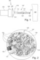
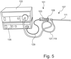
- An endoscopic device 101 has a camera 103 with a camera zoom 105, a light source 133 adapted to the camera 103 and an endoscope 107 ( Fig. 1 and 5 ). In the distal direction, after the camera 103 and the camera zoom 105, there is an eyepiece 109 of the endoscope 107.
- the endoscope 107 has an elongated shaft 111 in addition to the eyepiece 109.
- a light guide 119 is connected to the endoscope 107 via a light guide connection in a supply hose 127 and the camera 103 is connected to an image and data processing device 135 via a video cable 129 ( Fig. 5 ).
- the light guide 119 is connected to the light source 133 for feeding light into the light guide 119.
- the endoscope 107 has two rod lenses 113.
- the shaft 111 is closed at the distal end by a cover glass 115.
- the eyepiece 109 has a serial number 121 as an identification code.
- the first rod lens 113 has a bar code 123 on its distal side and the cover glass 115 has a QR code 125 on its proximal side.
- the endoscopic device 101 is already fully configured for the planned use for examining a tissue 130 ( Figure 1 ).
- the camera zoom 105 uses the camera zoom 105 to focus on a first marking zoom position for detecting the serial number 121 of the eyepiece 109, the serial number 121 is detected at the edge of the eyepiece 109 and the image data is evaluated and the serial number 121 is identified using the image and data processing device 135.
- the camera 103 then focuses on a second marking zoom position for detecting the bar code 123 on the distal side of the first rod lens 113 using the camera zoom 105.
- the corresponding The image data recorded are also evaluated and identified for the barcode 123, as with the serial number 121.
- the camera zoom 105 is used to focus on a third marking zoom position to capture the QR code 125 on the proximal side of the cover glass 115.
- the identification of the serial number 121 of the eyepiece 109, the bar code 123 of the first rod lens 113 and the QR code 125 of the cover glass 115 shows that the endoscope 107 is optimally suited for the planned endoscopic procedure on the tissue 130 and is suitable for use with the camera 103 and the light source 133.
- the examination of the tissue 130 is then immediately started by a user who brings the distal end of the shaft 111 of the endoscope 107 to the tissue 130.
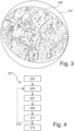
- the tissue 130 is clearly visible to the user without the serial number 121, the bar code 123 and the QR code 125 being visible in the image recording in the field of view 137 (see Figure 3 ).
- a method for configuration/identity verification 201 in which the endoscopic device 101 is first configured 203 for a planned, specific endoscopic use.
- the camera 103 is then focused 205 using the camera zoom 105, in which an image 207 of an optical marking 121, 123 or 125 is recorded using the camera 103 in a defined marking zoom position.
- the recorded image 209 is analyzed using an image and/or data processing device (step 209) and the optical marking is identified 211. If there are further optical markings in the endoscopic device 101, steps 205 to 211 are repeated 213 or the result of the identification 211 is output to the user (step 215).
- the output 215 to the user can take the form of a warning signal, a display and/or an enabling or blocking of a function of the endoscopic device 101.
- an endoscopic device 101 in which the identity of the endoscope 107 is checked promptly using the image-recording camera 103 before the actually planned use of the already configured endoscopic device 101 and, if the identification is positive, the endoscopic device 101 is immediately released for the use to be carried out. Consequently, the same endoscopic device 101 enables both the identity of the individual components of the endoscope 107 and thus of the endoscope 107 itself, as well as the specified examination of the tissue 130.
Landscapes
- Physics & Mathematics (AREA)
- Health & Medical Sciences (AREA)
- Engineering & Computer Science (AREA)
- Life Sciences & Earth Sciences (AREA)
- Surgery (AREA)
- Optics & Photonics (AREA)
- General Physics & Mathematics (AREA)
- General Health & Medical Sciences (AREA)
- Astronomy & Astrophysics (AREA)
- Pathology (AREA)
- Biomedical Technology (AREA)
- Heart & Thoracic Surgery (AREA)
- Medical Informatics (AREA)
- Molecular Biology (AREA)
- Animal Behavior & Ethology (AREA)
- Public Health (AREA)
- Veterinary Medicine (AREA)
- Nuclear Medicine, Radiotherapy & Molecular Imaging (AREA)
- Biophysics (AREA)
- Radiology & Medical Imaging (AREA)
- Theoretical Computer Science (AREA)
- Multimedia (AREA)
- Electromagnetism (AREA)
- Toxicology (AREA)
- Artificial Intelligence (AREA)
- Computer Vision & Pattern Recognition (AREA)
- Signal Processing (AREA)
- Oral & Maxillofacial Surgery (AREA)
- Endoscopes (AREA)
Claims (13)
- Dispositif endoscopique (101), notamment dispositif endoscopique médical ou industriel, le dispositif endoscopique (101) présentant en tant que composants une source de lumière, un guide de lumière (119), une caméra (103) et un endoscope (107) avec un élément optique (109, 113, 115) ou plusieurs éléments optiques, au moins un élément optique (109, 113, 115) présentant un marquage optique (121, 123, 125) pour vérifier une identité de l'élément optique (109, 113, 115) et/ou de l'endoscope (107) de telle sorte que le marquage optique (121, 123, 125) peut être détecté par la caméra (103) pour vérifier l'identité et/ou une configuration du dispositif endoscopique (101), caractérisé en ce que la caméra (103) présente un objectif de zoom (105) avec un moyen de réglage pour modifier une distance focale de telle sorte qu'avec l'objectif de zoom (105), le marquage optique ou les marquages optiques (121, 123, 125) peuvent être détectés dans une zone allant d'une extrémité proximale à une extrémité distale de l'endoscope (107) respectivement dans une position de zoom de marquage définie.
- Dispositif endoscopique (101) selon la revendication 1, caractérisé en ce que deux éléments optiques, trois éléments optiques (109, 113, 115) et/ou plusieurs éléments optiques présentent chacun un marquage optique.
- Dispositif endoscopique (101) selon la revendication 1 ou 2, caractérisé en ce que l'élément optique et/ou les éléments optiques sont un oculaire (109), une lentille, notamment une lentille à tige (113), et/ou un verre de couverture (115).
- Dispositif endoscopique (101) selon l'une quelconque des revendications précédentes, caractérisé en ce que l'objectif de zoom (105) peut être réglé au moyen du moyen de réglage de telle sorte que, dans une position de zoom d'objet pour observer un objet (130) à examiner, une image de la caméra (103) dans la position de zoom d'objet est exempte du marquage optique ou des marquages optiques (121, 123, 125).
- Dispositif endoscopique (101) selon l'une quelconque des revendications précédentes, caractérisé en ce que le marquage optique ou les marquages optiques est ou sont un marquage à barres (123), un marquage de couleur, un code QR (125), un numéro de série (121) et/ou un texte clair.
- Dispositif endoscopique (101) selon l'une quelconque des revendications précédentes, caractérisé en ce que le marquage optique (121, 123, 125) est décapé, gravé, gravé au laser, imprimé et/ou écrit dans et/ou sur l'élément optique ou les éléments optiques (109, 113, 115).
- Dispositif endoscopique (101) selon l'une quelconque des revendications précédentes, caractérisé en ce que le marquage optique (121, 123, 125) est agencé au centre, sur le bord extérieur et/ou en travers d'une surface de l'élément optique ou des éléments optiques (109, 113, 115).
- Dispositif endoscopique (101) selon l'une quelconque des revendications précédentes, caractérisé en ce que le marquage optique (121, 123, 125) présente un colorant, notamment un colorant UV et/ou fluorescent.
- Dispositif endoscopique (101) selon l'une quelconque des revendications précédentes, caractérisé en ce qu'un dispositif de traitement d'images et/ou de données est associé au dispositif endoscopique (101) pour évaluer et traiter une image enregistrée et/ou identifier le marquage optique respectif (121, 123, 125) de l'élément optique et/ou des éléments optiques (109, 113, 115) ou le dispositif endoscopique (101) présente le dispositif de traitement d'images et/ou de données.
- Procédé (201) de vérification de l'identité d'un composant d'un dispositif endoscopique (101) selon l'une quelconque des revendications 1 à 9, avec les étapes suivantes :- la configuration (203) du dispositif endoscopique (101) en agençant et/ou en reliant la source de lumière, le guide de lumière (119), la caméra (103) et l'endoscope (107) présentant un élément optique ou plusieurs éléments optiques (109, 113, 115),- la focalisation (205) de la caméra (103) sur au moins un marquage optique (121, 123, 125) de l'un des éléments optiques (109, 113, 115), l'objectif de zoom (105) détectant le marquage optique ou les marquages optiques (121, 123, 125) dans une zone allant d'une extrémité proximale à une extrémité distale de l'endoscope (107), respectivement dans une position de zoom de marquage définie,- l'enregistrement (207) d'une image de l'au moins un marquage optique (121, 123, 125) au moyen de la caméra (103),- l'analyse (209) de l'image enregistrée et l'identification (211) de l'au moins un marquage optique (121, 123, 125) et/ou de l'élément optique (109, 113, 115) de l'endoscope (107),- la répétition (213) de la focalisation (205), de l'enregistrement (207), de l'analyse (209) et de l'identification (211) d'un autre marquage optique (121, 123, 125) d'un autre élément optique (109, 113, 115) et/ou l'émission (215) d'un résultat de l'identification (211) pour une application médicale ou industrielle du dispositif endoscopique configuré (101).
- Procédé (201) selon la revendication 10, caractérisé en ce que, lors de la focalisation (205) de la caméra (103) sur un objet (130) à examiner, le marquage optique ou les marquages optiques (121, 123, 125) ne sont pas visibles.
- Procédé (201) selon l'une quelconque des revendications 10 ou 11, caractérisé en ce que la focalisation (205) de la caméra (103) est effectuée automatiquement lors d'une liaison à l'endoscope (107) ou lors de la mise sous tension de l'endoscope (107).
- Produit programme d'ordinateur pour évaluer un enregistrement d'image d'un marquage optique (121, 123, 125) d'un élément optique (109, 113, 115) et pour identifier un endoscope (107) d'un dispositif endoscopique (101) selon la revendication 9, le produit programme d'ordinateur présentant des instructions qui, lors de l'exécution du produit programme d'ordinateur par le dispositif de traitement d'images et/ou de données, permettent de reconnaître le marquage optique (121, 123, 125) détecté dans la position de zoom de marquage définie, 123, 125) dans l'enregistrement d'image, d'associer le marquage optique reconnu à un élément optique déterminé et/ou à un endoscope déterminé et ainsi d'identifier l'élément optique déterminé et/ou l'endoscope déterminé et, en option, d'émettre une notification à l'utilisateur du dispositif endoscopique (101).
Applications Claiming Priority (1)
| Application Number | Priority Date | Filing Date | Title |
|---|---|---|---|
| DE102020132454.5A DE102020132454B3 (de) | 2020-12-07 | 2020-12-07 | Endoskopische Vorrichtung und Verfahren zur Überprüfung einer Identität einer Komponente einer endoskopischen Vorrichtung |
Publications (2)
| Publication Number | Publication Date |
|---|---|
| EP4008233A1 EP4008233A1 (fr) | 2022-06-08 |
| EP4008233B1 true EP4008233B1 (fr) | 2025-01-15 |
Family
ID=78408852
Family Applications (1)
| Application Number | Title | Priority Date | Filing Date |
|---|---|---|---|
| EP21205458.9A Active EP4008233B1 (fr) | 2020-12-07 | 2021-10-29 | Dispositif endoscopique, procédé de vérification d'une identité d'un composant d'un dispositif endoscopique et produit-programme informatique |
Country Status (3)
| Country | Link |
|---|---|
| US (2) | US11954906B2 (fr) |
| EP (1) | EP4008233B1 (fr) |
| DE (1) | DE102020132454B3 (fr) |
Families Citing this family (2)
| Publication number | Priority date | Publication date | Assignee | Title |
|---|---|---|---|---|
| EP4169469A1 (fr) * | 2021-10-25 | 2023-04-26 | Erbe Vision GmbH | Agencement de caméra laparoscopique et procédé de correction d'erreur d'alignement de la caméra |
| DE102023118298B3 (de) | 2023-07-11 | 2024-10-24 | Schölly Fiberoptic GmbH | Endoskop mit einem in einem Strahlengang positionierten Element sowie Verfahren zur Identifizierung eines Endoskops |
Family Cites Families (22)
| Publication number | Priority date | Publication date | Assignee | Title |
|---|---|---|---|---|
| US6847490B1 (en) | 1997-01-13 | 2005-01-25 | Medispectra, Inc. | Optical probe accessory device for use in vivo diagnostic procedures |
| AU4080700A (en) | 1999-04-07 | 2000-10-23 | Blue Lake Products, Inc. | Identification of protective covers for medical imaging devices |
| DE20213926U1 (de) | 2002-09-10 | 2002-10-31 | Olympus Winter & Ibe Gmbh, 22045 Hamburg | Endoskopoptik |
| JP5085996B2 (ja) | 2006-10-25 | 2012-11-28 | テルモ株式会社 | マニピュレータシステム |
| US7794396B2 (en) * | 2006-11-03 | 2010-09-14 | Stryker Corporation | System and method for the automated zooming of a surgical camera |
| DE102006054148B4 (de) | 2006-11-16 | 2009-07-09 | Ioss Intelligente Optische Sensoren & Systeme Gmbh | Vorrichtung zum optischen Erfassen von Störungen an Körpern aus transparentem Material mit wenigstens einer ebenen Grenzfläche optischer Güte |
| US8366001B2 (en) * | 2008-08-14 | 2013-02-05 | Varioptic S.A. | Calibration methods for imaging systems and imaging systems using such |
| NL2004777B3 (nl) | 2010-05-28 | 2025-09-02 | Dovideq Medical Systems B V | Inrichting voor het testen van een optiek. |
| US9979949B2 (en) * | 2011-07-13 | 2018-05-22 | Viking Systems, Inc | Method and apparatus for obtaining stereoscopic 3D visualization using commercially available 2D endoscopes |
| US20130046299A1 (en) | 2011-08-18 | 2013-02-21 | John J. Newkirk | Intelligent electrosurgical electrode and tracking system |
| US9364249B2 (en) | 2012-03-22 | 2016-06-14 | Ethicon Endo-Surgery, Llc | Method and apparatus for programming modular surgical instrument |
| DE102013101158A1 (de) | 2013-02-06 | 2014-08-07 | Karl Storz Gmbh & Co. Kg | Medizinische Vorrichtung und Verfahren zum Konfigurieren eines medizinischen Systems |
| DE102013002832A1 (de) | 2013-03-25 | 2014-09-25 | Rg Mechatronics Gmbh | Roboter für die HF-Chirurgie |
| JP5767412B2 (ja) | 2013-06-12 | 2015-08-19 | オリンパス株式会社 | 内視鏡システム |
| DE102014109888B4 (de) | 2014-07-15 | 2022-12-01 | Karl Storz Se & Co. Kg | Verfahren und Vorrichtung zum Prüfen der Licht- und/oder Bildübertragungseigenschaften eines endoskopischen oder exoskopischen Systems |
| DE102014217095A1 (de) | 2014-08-27 | 2016-03-03 | Olympus Winter & Ibe Gmbh | Elektrochirurgisches System und Verfahren zum Betreiben desselben |
| DE102015016233A1 (de) | 2015-12-16 | 2017-06-22 | Karl Storz Gmbh & Co. Kg | RFID-Transponder für ein medizinisches Instrument und/oder für ein Endoskop, medizinisches Instrument und/oder Endoskop sowie Montageverfahren |
| DE102016214990B4 (de) * | 2016-08-11 | 2021-09-23 | Olympus Winter & Ibe Gmbh | Optisches System, chirurgisches Instrument und Verfahren und Einrichtung zum Montieren eines optischen Systems |
| DE102017103804B4 (de) | 2017-02-23 | 2024-10-17 | Schölly Fiberoptic GmbH | Endoskopisches Bildaufnahmeverfahren und zugehörige Vorrichtung |
| US10722102B2 (en) | 2017-09-05 | 2020-07-28 | Arthrex, Inc. | Endoscope field stop encoding system and method |
| US20200187766A1 (en) * | 2018-12-17 | 2020-06-18 | Z Square Ltd | Enhanced multicore fiber endoscopes |
| US11166623B2 (en) | 2019-04-23 | 2021-11-09 | Arthrex, Inc. | Field stop fluorescent indicator system and method |
-
2020
- 2020-12-07 DE DE102020132454.5A patent/DE102020132454B3/de active Active
-
2021
- 2021-10-27 US US17/511,793 patent/US11954906B2/en active Active
- 2021-10-29 EP EP21205458.9A patent/EP4008233B1/fr active Active
-
2024
- 2024-02-15 US US18/442,873 patent/US20240185597A1/en active Pending
Also Published As
| Publication number | Publication date |
|---|---|
| DE102020132454B3 (de) | 2021-11-25 |
| US11954906B2 (en) | 2024-04-09 |
| US20220180096A1 (en) | 2022-06-09 |
| EP4008233A1 (fr) | 2022-06-08 |
| US20240185597A1 (en) | 2024-06-06 |
Similar Documents
| Publication | Publication Date | Title |
|---|---|---|
| DE102014109888B4 (de) | Verfahren und Vorrichtung zum Prüfen der Licht- und/oder Bildübertragungseigenschaften eines endoskopischen oder exoskopischen Systems | |
| EP0998239B1 (fr) | Instrument endoscopique pour interventions ou examens endoscopiques et appareillage endoscopique renfermant un tel instrument | |
| EP2335556B1 (fr) | Dispositif de contrôle d'un système d'analyse optique | |
| EP2921110B1 (fr) | Détection automatique de la profondeur de pénétration et de l'orientation rotative d'un instrument invasif | |
| EP4008233B1 (fr) | Dispositif endoscopique, procédé de vérification d'une identité d'un composant d'un dispositif endoscopique et produit-programme informatique | |
| DE102005015522A1 (de) | Intrakorporale Videokapsel mit schwenkbarem Bildaufnehmer | |
| EP0794731A2 (fr) | Dispositif d'examen de la peau | |
| EP3560410B1 (fr) | Dispositif pour la manipulation stérile d'un endoscope non stérile dans un environnement stérile | |
| WO2016134904A1 (fr) | Instrument médical | |
| EP3289960A2 (fr) | Système d'éclairage pourvu d'ensemble fibreux hétérogène | |
| DE102021133947A1 (de) | Medizinische Bildgebungsvorrichtung, insbesondere Endoskop, Exoskop und/oder Laparoskop | |
| EP2306750A1 (fr) | Procédé et dispositif destinés à la vérification d'endoscopes | |
| EP3253271B1 (fr) | Oculaire pour un instrument chirurgical | |
| DE102010043796A1 (de) | Zahnärztliches System zum Transilluminieren von Zähnen | |
| DE102017103804B4 (de) | Endoskopisches Bildaufnahmeverfahren und zugehörige Vorrichtung | |
| DE102019108117A1 (de) | Verfahren zum Herstellen eines Endoskops | |
| DE102022131502A1 (de) | Filterschaltvorrichtung für einen endoskopischen Kamerakopf, Kamerakopf und Nachrüstsatz zum Nachrüsten eines Kamerakopfs und/oder eines Endoskops | |
| DE102020132818A1 (de) | Verfahren zur spektralen Überprüfung von Systemkomponenten eines modularen medizinischen Bildgebungssystems | |
| DE102023125039B3 (de) | Endoskopvorrichtung und Endoskop mit einer Endoskopvorrichtung | |
| DE202017003565U1 (de) | Vorrichtung zum Schutz endoskopischer Komponenten vor ungewollter Laserapplikation | |
| EP3713466B1 (fr) | Système d'assistance à un utilisateur pour des produits médicaux réutilisables | |
| DE102024130153A1 (de) | Bilderzeugungsvorrichtung | |
| DE102024125174A1 (de) | Verfahren zur messtechnischen Erfassung eines Degradationszustands eines endoskopischen Bildgebungssystems | |
| DE102023103357A1 (de) | Aufsatzoptik und System zur Fluoreszenzbildgebung bei offener Chirurgie | |
| WO2006105941A2 (fr) | Dispositif et procede pour l'examen optique du corps humain ou animal |
Legal Events
| Date | Code | Title | Description |
|---|---|---|---|
| PUAI | Public reference made under article 153(3) epc to a published international application that has entered the european phase |
Free format text: ORIGINAL CODE: 0009012 |
|
| STAA | Information on the status of an ep patent application or granted ep patent |
Free format text: STATUS: THE APPLICATION HAS BEEN PUBLISHED |
|
| AK | Designated contracting states |
Kind code of ref document: A1 Designated state(s): AL AT BE BG CH CY CZ DE DK EE ES FI FR GB GR HR HU IE IS IT LI LT LU LV MC MK MT NL NO PL PT RO RS SE SI SK SM TR |
|
| STAA | Information on the status of an ep patent application or granted ep patent |
Free format text: STATUS: REQUEST FOR EXAMINATION WAS MADE |
|
| 17P | Request for examination filed |
Effective date: 20221201 |
|
| RBV | Designated contracting states (corrected) |
Designated state(s): AL AT BE BG CH CY CZ DE DK EE ES FI FR GB GR HR HU IE IS IT LI LT LU LV MC MK MT NL NO PL PT RO RS SE SI SK SM TR |
|
| P01 | Opt-out of the competence of the unified patent court (upc) registered |
Effective date: 20230527 |
|
| GRAP | Despatch of communication of intention to grant a patent |
Free format text: ORIGINAL CODE: EPIDOSNIGR1 |
|
| STAA | Information on the status of an ep patent application or granted ep patent |
Free format text: STATUS: GRANT OF PATENT IS INTENDED |
|
| INTG | Intention to grant announced |
Effective date: 20240920 |
|
| GRAJ | Information related to disapproval of communication of intention to grant by the applicant or resumption of examination proceedings by the epo deleted |
Free format text: ORIGINAL CODE: EPIDOSDIGR1 |
|
| STAA | Information on the status of an ep patent application or granted ep patent |
Free format text: STATUS: REQUEST FOR EXAMINATION WAS MADE |
|
| GRAP | Despatch of communication of intention to grant a patent |
Free format text: ORIGINAL CODE: EPIDOSNIGR1 |
|
| STAA | Information on the status of an ep patent application or granted ep patent |
Free format text: STATUS: GRANT OF PATENT IS INTENDED |
|
| INTC | Intention to grant announced (deleted) | ||
| GRAS | Grant fee paid |
Free format text: ORIGINAL CODE: EPIDOSNIGR3 |
|
| INTG | Intention to grant announced |
Effective date: 20241108 |
|
| GRAA | (expected) grant |
Free format text: ORIGINAL CODE: 0009210 |
|
| STAA | Information on the status of an ep patent application or granted ep patent |
Free format text: STATUS: THE PATENT HAS BEEN GRANTED |
|
| AK | Designated contracting states |
Kind code of ref document: B1 Designated state(s): AL AT BE BG CH CY CZ DE DK EE ES FI FR GB GR HR HU IE IS IT LI LT LU LV MC MK MT NL NO PL PT RO RS SE SI SK SM TR |
|
| REG | Reference to a national code |
Ref country code: CH Ref legal event code: EP Ref country code: GB Ref legal event code: FG4D Free format text: NOT ENGLISH |
|
| REG | Reference to a national code |
Ref country code: DE Ref legal event code: R096 Ref document number: 502021006425 Country of ref document: DE |
|
| REG | Reference to a national code |
Ref country code: IE Ref legal event code: FG4D Free format text: LANGUAGE OF EP DOCUMENT: GERMAN |
|
| REG | Reference to a national code |
Ref country code: NL Ref legal event code: MP Effective date: 20250115 |
|
| PG25 | Lapsed in a contracting state [announced via postgrant information from national office to epo] |
Ref country code: NL Free format text: LAPSE BECAUSE OF FAILURE TO SUBMIT A TRANSLATION OF THE DESCRIPTION OR TO PAY THE FEE WITHIN THE PRESCRIBED TIME-LIMIT Effective date: 20250115 |
|
| PG25 | Lapsed in a contracting state [announced via postgrant information from national office to epo] |
Ref country code: RS Free format text: LAPSE BECAUSE OF FAILURE TO SUBMIT A TRANSLATION OF THE DESCRIPTION OR TO PAY THE FEE WITHIN THE PRESCRIBED TIME-LIMIT Effective date: 20250415 |
|
| PG25 | Lapsed in a contracting state [announced via postgrant information from national office to epo] |
Ref country code: FI Free format text: LAPSE BECAUSE OF FAILURE TO SUBMIT A TRANSLATION OF THE DESCRIPTION OR TO PAY THE FEE WITHIN THE PRESCRIBED TIME-LIMIT Effective date: 20250115 |
|
| PG25 | Lapsed in a contracting state [announced via postgrant information from national office to epo] |
Ref country code: PL Free format text: LAPSE BECAUSE OF FAILURE TO SUBMIT A TRANSLATION OF THE DESCRIPTION OR TO PAY THE FEE WITHIN THE PRESCRIBED TIME-LIMIT Effective date: 20250115 |
|
| PG25 | Lapsed in a contracting state [announced via postgrant information from national office to epo] |
Ref country code: ES Free format text: LAPSE BECAUSE OF FAILURE TO SUBMIT A TRANSLATION OF THE DESCRIPTION OR TO PAY THE FEE WITHIN THE PRESCRIBED TIME-LIMIT Effective date: 20250115 |
|
| REG | Reference to a national code |
Ref country code: LT Ref legal event code: MG9D |
|
| PG25 | Lapsed in a contracting state [announced via postgrant information from national office to epo] |
Ref country code: IS Free format text: LAPSE BECAUSE OF FAILURE TO SUBMIT A TRANSLATION OF THE DESCRIPTION OR TO PAY THE FEE WITHIN THE PRESCRIBED TIME-LIMIT Effective date: 20250515 Ref country code: NO Free format text: LAPSE BECAUSE OF FAILURE TO SUBMIT A TRANSLATION OF THE DESCRIPTION OR TO PAY THE FEE WITHIN THE PRESCRIBED TIME-LIMIT Effective date: 20250415 |
|
| PG25 | Lapsed in a contracting state [announced via postgrant information from national office to epo] |
Ref country code: HR Free format text: LAPSE BECAUSE OF FAILURE TO SUBMIT A TRANSLATION OF THE DESCRIPTION OR TO PAY THE FEE WITHIN THE PRESCRIBED TIME-LIMIT Effective date: 20250115 |
|
| PG25 | Lapsed in a contracting state [announced via postgrant information from national office to epo] |
Ref country code: PT Free format text: LAPSE BECAUSE OF FAILURE TO SUBMIT A TRANSLATION OF THE DESCRIPTION OR TO PAY THE FEE WITHIN THE PRESCRIBED TIME-LIMIT Effective date: 20250515 Ref country code: LV Free format text: LAPSE BECAUSE OF FAILURE TO SUBMIT A TRANSLATION OF THE DESCRIPTION OR TO PAY THE FEE WITHIN THE PRESCRIBED TIME-LIMIT Effective date: 20250115 |
|
| PG25 | Lapsed in a contracting state [announced via postgrant information from national office to epo] |
Ref country code: BG Free format text: LAPSE BECAUSE OF FAILURE TO SUBMIT A TRANSLATION OF THE DESCRIPTION OR TO PAY THE FEE WITHIN THE PRESCRIBED TIME-LIMIT Effective date: 20250115 Ref country code: GR Free format text: LAPSE BECAUSE OF FAILURE TO SUBMIT A TRANSLATION OF THE DESCRIPTION OR TO PAY THE FEE WITHIN THE PRESCRIBED TIME-LIMIT Effective date: 20250416 |
|
| PG25 | Lapsed in a contracting state [announced via postgrant information from national office to epo] |
Ref country code: SE Free format text: LAPSE BECAUSE OF FAILURE TO SUBMIT A TRANSLATION OF THE DESCRIPTION OR TO PAY THE FEE WITHIN THE PRESCRIBED TIME-LIMIT Effective date: 20250115 |
|
| PG25 | Lapsed in a contracting state [announced via postgrant information from national office to epo] |
Ref country code: SM Free format text: LAPSE BECAUSE OF FAILURE TO SUBMIT A TRANSLATION OF THE DESCRIPTION OR TO PAY THE FEE WITHIN THE PRESCRIBED TIME-LIMIT Effective date: 20250115 |
|
| PG25 | Lapsed in a contracting state [announced via postgrant information from national office to epo] |
Ref country code: DK Free format text: LAPSE BECAUSE OF FAILURE TO SUBMIT A TRANSLATION OF THE DESCRIPTION OR TO PAY THE FEE WITHIN THE PRESCRIBED TIME-LIMIT Effective date: 20250115 |
|
| REG | Reference to a national code |
Ref country code: DE Ref legal event code: R097 Ref document number: 502021006425 Country of ref document: DE |
|
| PG25 | Lapsed in a contracting state [announced via postgrant information from national office to epo] |
Ref country code: CZ Free format text: LAPSE BECAUSE OF FAILURE TO SUBMIT A TRANSLATION OF THE DESCRIPTION OR TO PAY THE FEE WITHIN THE PRESCRIBED TIME-LIMIT Effective date: 20250115 Ref country code: EE Free format text: LAPSE BECAUSE OF FAILURE TO SUBMIT A TRANSLATION OF THE DESCRIPTION OR TO PAY THE FEE WITHIN THE PRESCRIBED TIME-LIMIT Effective date: 20250115 |
|
| PG25 | Lapsed in a contracting state [announced via postgrant information from national office to epo] |
Ref country code: RO Free format text: LAPSE BECAUSE OF FAILURE TO SUBMIT A TRANSLATION OF THE DESCRIPTION OR TO PAY THE FEE WITHIN THE PRESCRIBED TIME-LIMIT Effective date: 20250115 |
|
| PG25 | Lapsed in a contracting state [announced via postgrant information from national office to epo] |
Ref country code: SK Free format text: LAPSE BECAUSE OF FAILURE TO SUBMIT A TRANSLATION OF THE DESCRIPTION OR TO PAY THE FEE WITHIN THE PRESCRIBED TIME-LIMIT Effective date: 20250115 |
|
| REG | Reference to a national code |
Ref country code: CH Ref legal event code: U11 Free format text: ST27 STATUS EVENT CODE: U-0-0-U10-U11 (AS PROVIDED BY THE NATIONAL OFFICE) Effective date: 20251101 |
|
| PLBE | No opposition filed within time limit |
Free format text: ORIGINAL CODE: 0009261 |
|
| STAA | Information on the status of an ep patent application or granted ep patent |
Free format text: STATUS: NO OPPOSITION FILED WITHIN TIME LIMIT |
|
| 26N | No opposition filed |
Effective date: 20251016 |
|
| PGFP | Annual fee paid to national office [announced via postgrant information from national office to epo] |
Ref country code: DE Payment date: 20251028 Year of fee payment: 5 |
|
| PGFP | Annual fee paid to national office [announced via postgrant information from national office to epo] |
Ref country code: GB Payment date: 20251023 Year of fee payment: 5 |
|
| PGFP | Annual fee paid to national office [announced via postgrant information from national office to epo] |
Ref country code: AT Payment date: 20260113 Year of fee payment: 5 |
|
| PGFP | Annual fee paid to national office [announced via postgrant information from national office to epo] |
Ref country code: IT Payment date: 20251022 Year of fee payment: 5 |
|
| PGFP | Annual fee paid to national office [announced via postgrant information from national office to epo] |
Ref country code: FR Payment date: 20251027 Year of fee payment: 5 |
|
| PGFP | Annual fee paid to national office [announced via postgrant information from national office to epo] |
Ref country code: CH Payment date: 20251101 Year of fee payment: 5 |