EP4008247A1 - Induktives sensorsystem zur messung elektromagnetischer signale aus einem körper - Google Patents
Induktives sensorsystem zur messung elektromagnetischer signale aus einem körper Download PDFInfo
- Publication number
- EP4008247A1 EP4008247A1 EP20211050.8A EP20211050A EP4008247A1 EP 4008247 A1 EP4008247 A1 EP 4008247A1 EP 20211050 A EP20211050 A EP 20211050A EP 4008247 A1 EP4008247 A1 EP 4008247A1
- Authority
- EP
- European Patent Office
- Prior art keywords
- amplitude
- circuit
- analog
- loop
- bits
- Prior art date
- Legal status (The legal status is an assumption and is not a legal conclusion. Google has not performed a legal analysis and makes no representation as to the accuracy of the status listed.)
- Withdrawn
Links
- 230000001939 inductive effect Effects 0.000 title claims abstract description 20
- 238000005259 measurement Methods 0.000 claims description 25
- 230000005284 excitation Effects 0.000 claims description 19
- 230000004044 response Effects 0.000 claims description 9
- 238000000034 method Methods 0.000 claims description 8
- 230000000644 propagated effect Effects 0.000 claims description 7
- 230000029058 respiratory gaseous exchange Effects 0.000 claims description 7
- 238000012545 processing Methods 0.000 claims description 6
- 230000008878 coupling Effects 0.000 claims description 5
- 238000010168 coupling process Methods 0.000 claims description 5
- 238000005859 coupling reaction Methods 0.000 claims description 5
- 239000003990 capacitor Substances 0.000 claims description 4
- 230000001902 propagating effect Effects 0.000 claims description 4
- 230000010355 oscillation Effects 0.000 abstract description 4
- 238000013016 damping Methods 0.000 description 12
- 238000012544 monitoring process Methods 0.000 description 9
- 230000008859 change Effects 0.000 description 7
- 230000008901 benefit Effects 0.000 description 6
- 230000000694 effects Effects 0.000 description 6
- 230000004907 flux Effects 0.000 description 6
- 230000006698 induction Effects 0.000 description 6
- 230000033001 locomotion Effects 0.000 description 6
- 210000000038 chest Anatomy 0.000 description 5
- 239000004020 conductor Substances 0.000 description 5
- 230000007423 decrease Effects 0.000 description 5
- 230000003247 decreasing effect Effects 0.000 description 5
- 230000006870 function Effects 0.000 description 5
- 210000004072 lung Anatomy 0.000 description 4
- 230000005684 electric field Effects 0.000 description 3
- 230000001965 increasing effect Effects 0.000 description 3
- 230000035515 penetration Effects 0.000 description 3
- 230000033228 biological regulation Effects 0.000 description 2
- 230000001419 dependent effect Effects 0.000 description 2
- 238000001514 detection method Methods 0.000 description 2
- 230000005672 electromagnetic field Effects 0.000 description 2
- 238000005516 engineering process Methods 0.000 description 2
- 230000008569 process Effects 0.000 description 2
- 230000000638 stimulation Effects 0.000 description 2
- 239000000853 adhesive Substances 0.000 description 1
- 230000001070 adhesive effect Effects 0.000 description 1
- 239000008280 blood Substances 0.000 description 1
- 210000004369 blood Anatomy 0.000 description 1
- 210000004204 blood vessel Anatomy 0.000 description 1
- 230000000747 cardiac effect Effects 0.000 description 1
- 238000004590 computer program Methods 0.000 description 1
- 230000005670 electromagnetic radiation Effects 0.000 description 1
- 230000010247 heart contraction Effects 0.000 description 1
- 238000009532 heart rate measurement Methods 0.000 description 1
- 238000002847 impedance measurement Methods 0.000 description 1
- 230000010354 integration Effects 0.000 description 1
- 238000011835 investigation Methods 0.000 description 1
- 239000012811 non-conductive material Substances 0.000 description 1
- 230000003287 optical effect Effects 0.000 description 1
- 238000013186 photoplethysmography Methods 0.000 description 1
- 238000013139 quantization Methods 0.000 description 1
- 210000002321 radial artery Anatomy 0.000 description 1
- 239000004065 semiconductor Substances 0.000 description 1
- 230000009131 signaling function Effects 0.000 description 1
- 238000001228 spectrum Methods 0.000 description 1
- 239000004753 textile Substances 0.000 description 1
- 238000004804 winding Methods 0.000 description 1
Images

Classifications
-
- A—HUMAN NECESSITIES
- A61—MEDICAL OR VETERINARY SCIENCE; HYGIENE
- A61B—DIAGNOSIS; SURGERY; IDENTIFICATION
- A61B5/00—Measuring for diagnostic purposes; Identification of persons
- A61B5/05—Detecting, measuring or recording for diagnosis by means of electric currents or magnetic fields; Measuring using microwaves or radio waves
- A61B5/0522—Magnetic induction tomography
-
- A—HUMAN NECESSITIES
- A61—MEDICAL OR VETERINARY SCIENCE; HYGIENE
- A61B—DIAGNOSIS; SURGERY; IDENTIFICATION
- A61B5/00—Measuring for diagnostic purposes; Identification of persons
- A61B5/05—Detecting, measuring or recording for diagnosis by means of electric currents or magnetic fields; Measuring using microwaves or radio waves
-
- A—HUMAN NECESSITIES
- A61—MEDICAL OR VETERINARY SCIENCE; HYGIENE
- A61B—DIAGNOSIS; SURGERY; IDENTIFICATION
- A61B5/00—Measuring for diagnostic purposes; Identification of persons
- A61B5/72—Signal processing specially adapted for physiological signals or for diagnostic purposes
- A61B5/7225—Details of analogue processing, e.g. isolation amplifier, gain or sensitivity adjustment, filtering, baseline or drift compensation
-
- H—ELECTRICITY
- H03—ELECTRONIC CIRCUITRY
- H03B—GENERATION OF OSCILLATIONS, DIRECTLY OR BY FREQUENCY-CHANGING, BY CIRCUITS EMPLOYING ACTIVE ELEMENTS WHICH OPERATE IN A NON-SWITCHING MANNER; GENERATION OF NOISE BY SUCH CIRCUITS
- H03B5/00—Generation of oscillations using amplifier with regenerative feedback from output to input
- H03B5/08—Generation of oscillations using amplifier with regenerative feedback from output to input with frequency-determining element comprising lumped inductance and capacitance
- H03B5/12—Generation of oscillations using amplifier with regenerative feedback from output to input with frequency-determining element comprising lumped inductance and capacitance active element in amplifier being semiconductor device
- H03B5/1206—Generation of oscillations using amplifier with regenerative feedback from output to input with frequency-determining element comprising lumped inductance and capacitance active element in amplifier being semiconductor device using multiple transistors for amplification
- H03B5/1212—Generation of oscillations using amplifier with regenerative feedback from output to input with frequency-determining element comprising lumped inductance and capacitance active element in amplifier being semiconductor device using multiple transistors for amplification the amplifier comprising a pair of transistors, wherein an output terminal of each being connected to an input terminal of the other, e.g. a cross coupled pair
Definitions
- This invention relates to an inductive sensing system for sensing electromagnetic signals from a body, and in particular a sensor for inductively coupling with a body for sensing electromagnetic signals.
- kymographic sensors Sensors that measure mechanical activity are called kymographic sensors.
- kymographic biometric sensors are accelerometer-based biosensors, transthoracic impedance biosensors, radar-based biosensors, and photoplethysmography sensors.
- Inductive sensors have the potential to become a game-changer in the field of patient monitoring, because the biometric signals are relatively motion tolerant. Inductive sensing has application in wearable patient monitors, motion tolerant respiration measurements, contactless patient monitoring, and spot-check measurements. Inductive sensing thus generally provides a means of non-invasive investigation of properties of a body.
- inductive sensing can be used as a means of non-invasively investigating physiological characteristics, in particular heart and lung dynamics.
- Inductive sensing is based on magnetic induction and has several advantages over conductive and capacitive sensing.
- An advantage compared to conductive sensing, such as bio-impedance measurements, is that adhesive electrodes are not required; sensing may be performed without contact and/or through non-conductive material, such as textile and plastic.
- inductive sensing is based on magnetic fields rather than electric fields and as a result is more sensitive to changes at greater penetration depth inside the body, as opposed to those just occurring at skin level. This is because magnetic fields penetrate deeper into a body than electrical fields, and thus magnetic fields can be used to measure changes in properties deeper inside the body, whereas electrical fields are predominantly useful only for measuring effects at the surface of the skin such as changes in skin properties (e.g. permittivity) or movement of the skin (skin proximity).
- Coil-based inductive sensors function by inductively coupling with electromagnetic signals (i.e. electromagnetic waves or oscillations), wherein propagation of the signals through the coil leads to a change in the current through the coil, which can be measured and used to sense properties of the propagated signal (including e.g. frequency spectrum, amplitude and phase pattern).
- electromagnetic signals i.e. electromagnetic waves or oscillations
- An electromagnetic excitation signal can be propagated into a body to be investigated.
- the excitation electromagnetic signal causes magnetic induction in the body, i. e. the generation of eddy currents in the tissue of the body due to the application of an external magnetic field. These eddy currents then in turn generate electromagnetic signals propagated out of the body which interact with the applied fields in a way that allows them to be sensed by the coil.
- Movements of tissue in the body can manifest in changes in volumes of local regions of the tissue and in changes of the conductive or dielectric properties of a tissue. These changes then cause amplitude and/or phase modulations of the electromagnetic signal which is emitted out of the body in response to the electromagnetic stimulation. By monitoring these changes, movement and size change of elements within the body can be detected and tracked, and changes in the conductivity and dielectric properties can be tracked. For example, heart contractions manifest themselves mainly as movement of blood, and breathing mainly manifests itself as changes in the conductivity of the lung.
- Recent inventions in the field of inductive sensing have enabled simple contactless measurements of the heart's and lung's mechanical activity, or the mechanical activity of a blood vessel like the radial artery in a human arm.
- a first challenge of inductive sensing technology is however to comply with electromagnetic compatibility (EMC) regulations. Especially in a clinical setting, the restrictions are stringent. Since it is an active measurement in the radio frequency (RF) range, there will always be exposed electromagnetic fields (near field) and emitted electromagnetic radiation (far field). The electric RF current in the antenna loop is the dominant source of exposed and emitted electromagnetic fields.
- EMC electromagnetic compatibility
- a second challenge is to minimize the power consumption for wearable body sensors, because of limited battery capacity. Meanwhile, the signal-to-noise ratio is typically decreased when using lower power consumption circuity, and care needs to be taken to enable a good enough signal quality for reliable measurement of vital signs.
- a physiological parameter inductive sensing system for sensing electromagnetic signals emitted from a body in response to electromagnetic excitation signals propagated into said body, the system comprising:
- the sensing system uses an analog to digital converter, ADC, with a lower resolution than the resolution of the output value, which is the output measurement signal from the circuit.
- ADC analog to digital converter
- the amplitude is controlled, but the desired information relating to the amplitude of the oscillation (which conveys the information about the electromagnetic signals emitted from the body) is captured by the feedback control signal.
- This feedback control signal stabilizes at a particular control level of the oscillator circuit, and this control level corresponds to a particular signal level emitted from the body.
- the feedback control signal functions as the measurement of the amplitude of the signal emitted from the body.
- the first number of bits may be 1.
- a simple 1 bit quantizer may be used as the analog to digital converter, which compares the input with a threshold to determine a 0 or 1 output.
- the first number of bits could also be 2, encoded in such a way that the ADC becomes a tri-state ADC.
- "00” means 'below reference'
- "01” and “10” means 'equal to reference'
- "11” means 'above reference'.
- the ADC could instead be a 1-trit ADC, which means it uses base-3 as a unit of information. This is equivalent to a 2 bit version that encodes a tri-state ADC.
- the amplitude measurement circuit may comprise a circuit for measuring the imaginary part of the complex reflected inductance.
- the feedback controller for example comprises a digital to analog converter.
- the feedback control loop uses analog control.
- the feedback controller for example comprises a circuit for controlling a bias current within the oscillator circuit.
- the circuit for controlling a bias current comprises a current mirror circuit for injecting a current into the oscillator circuit.
- the oscillator circuit comprises a drive transistor and the circuit for controlling a bias current comprises a circuit for introducing losses to the driver transistor.
- the loop antenna may comprise a loop capacitor, for setting the natural resonance frequency of the oscillator.
- a frequency of the electromagnetic excitation signals is for example from 30 MHz to 1000 MHz. Maintaining a frequency below 1000 MHz optimizes penetration depth. At frequencies above 1000 MHz, penetration depth of electromagnetic signals start to become prohibitively small for measuring physiological parameters, e.g. lung or heart signals. Signal strength however becomes larger above a 30 MHz frequency.
- a signal processing means may be provided for processing the output values over time to derive one or more physiological parameters.
- the physiological parameters may comprise a heart rate and/or a breathing rate.
- the invention also provides a method for sensing electromagnetic signals emitted from a body in response to electromagnetic excitation signals propagated into said body, the method comprising:
- the invention provides a physiological parameter inductive sensing system.
- a loop resonator inductively couples with electromagnetic signals emitted from the body.
- the loop resonator forms part of an oscillator circuit, and negative feedback control is used to control the oscillator circuit, based on a measured oscillation amplitude.
- an analog to digital converter is used with a first number of bits (or trits), and successive outputs of the analog to digital converter are combined to derive an output value with a resolution of a second number of bits, greater than the first number of bits (or trits).
- the feedback control of the amplitude of the oscillator circuit is achieved using the output value.
- An inductive coupling system makes use of a coil or wire which has induced across it a potential difference due to exposure to a time varying magnetic field. This principle may be used to measure the strength of electromagnetic signals generated within regions of a body by sensing changes in the inductance of a coil placed in proximity to the body, where these changes are detected based on changing resonance characteristics of the coil circuit.
- Any electrical conductor exhibits a property of self-inductance.
- Self-inductance is the property of an electrical conductor by which a change in the current being driven through the conductor results in induction of an electromotive force in the conductor.
- the induced electromotive force is in a direction such as to resist the change in current which is inducing it. It is hence commonly termed 'back-EMF'.
- Self-inductance can be understood as arising due to a magnetic flux induced as a result of the change in current (Ampere's law). This flux then interacts with the conductor itself to induce a back-EMF (Faraday's law of induction and Lenz' law).
- a resonator for example comprising a single turn loop antenna, may be used to stimulate or excite a body with electromagnetic signals (waves) and to sense signals emitted back from the body in response to those excitation signals.
- the coil may be driven with an alternating current to generate the excitation signals for propagation into the body.
- the inductance L acquires an additional reflected inductance component, L r , arising due to eddy currents induced in the stimulated body as a result of application of the excitation signals.
- Figure 1 illustrates the operation of an inductive sensing system, which shows by way of example a loop antenna 12 being driven with an alternating current in proximity to a thorax 16 of a subject, so as to propagate electromagnetic signals 22 into the thorax.
- the loop antenna functions as a loop resonator. It may include a series capacitor used to tune the natural resonance frequency.
- EMF electromotive force
- L r The added component of inductance arising from the eddy currents is referred to as 'reflected inductance', L r .
- Reflected inductance can be defined as: L r ⁇ 1 I ⁇ all turns A r ⁇ d l
- a r is the reflected part of the electromagnetic vector potential (i.e. the part that is generated by the eddy currents 18 in the stimulated medium)
- I is the coil current.
- the reflected inductance is closely related to the reflected impedance Z r .
- the magnitude of the reflected inductance component gives an indication of the strength of the 'reflected' electromagnetic signals emitted back from the body. Stronger signals give higher signal to noise ratio, which improves the quality and reliability of the sensed signals. By seeking to optimize the strength of Lr, the signal to noise ratio may thereby be maximized.
- L r the reflected inductance
- L r L r ⁇ + iL r ⁇
- L r ⁇ is related to a reactive impedance of the coil antenna
- L r ⁇ is related to resistive impedance of the coil.
- the addition of the reflected component of inductance L r leads to a detuning of the characteristics of the coil.
- both the natural radial frequency of the coil antenna circuit and the damping factor of the coil antenna circuit change.
- the magnitude of the reflected inductance L r can be determined, and the reflected signals measured.
- ⁇ 0 ,t is the natural undamped radial frequency of the coil circuit in the presence of a medium or body (the subscript t standing for 'total')
- ⁇ t is the (total) damping factor in the presence of a medium
- L r ⁇ is the real part of the reflected inductance defined in equation (7)
- the detuned natural radial frequency depends only on the real part of the reflected inductance L r ⁇ .
- the detuned damping factor depends also upon the imaginary part of the reflected inductance L r ⁇ . .
- the benefit of using the geometrically normalized quantities lies in the fact that L ⁇ 0 is independent of system size and the number of turns in the antenna coil.
- ⁇ 0, t the natural undamped radial frequency of the coil circuit in the presence of a medium or body (the subscript t standing for 'total')
- ⁇ t is the (total) damping factor in the presence of a medium
- L ⁇ r ⁇ is
- the reflected inductance is a complex quantity, it affects both the frequency and amplitude of the oscillator.
- Most inductive sensors focus only on the frequency, while in fact the amplitude is an independent signal that contains independent information.
- This amplitude variation is manifested in the damping factor described above, as the resonator damping modulates the oscillator amplitude.
- the amplitude variation is thus in particular expressed in the imaginary impedance component.
- FIG. 2 shows the most straightforward way to measure amplitude, and hence the damping.
- the input signal source is represented as an oscillator 30.
- the swing of the signal i.e. the oscillator tank swing
- the amplitude detector 32 is measured by an amplitude detector 32 and digitized in an analog to digital converter 34 to generate the amplitude measurement output 36.
- Figure 2 is an amplitude demodulation system.
- Such a system will have a large dynamic range (DR) to cover the damping measurement from free space to application of the sensor to the body.
- DR dynamic range
- This requires both high linearity and high resolution/low noise electronics, consuming significant amounts of power.
- Most of this dynamic range is not used once the sensor is applied to the body, but for every digitization step, the full dynamic range is cycled to determine the digital output bit stream.
- the loop antenna 12 will radiate the maximum amount of power when it is in free space, making it harder to comply with EMC regulations and as well as decreasing the signal-to-noise ratio (SNR) of the measurement when applied to the body.
- SNR signal-to-noise ratio
- the oscillator amplitude (and thereby the current in the loop) quickly exceeds the maximum current when it is not applied to a body, especially if the loop resistance is small. Also, when the loop is applied to the body, the total resistance of the loop increases which increases thermal noise and decreases the signal strength in free-running oscillators (i.e. oscillators without amplitude control).
- the electronics for the analog-to-digital converter are power hungry, because to cover the full dynamic range, a multi-bit ADC is needed.
- the multibit ADC has many components that need to be powered simultaneously, and for every ADC cycle, the full dynamic range needs to be covered requiring many sub-cycles that are repeated every sample to be digitized. Also, to cover such a large dynamic range, the ADC needs to have great linearity over the full range, increasing the power consumption as well.
- the invention is based on the use of an analog to digital converter with a reduced number of bits or trits, i.e. with a lower resolution than the resolution of the output value (i.e. the measurement signal provided by the circuit).
- the output of the analog to digital converter has a first number of bits (or trits).
- the output value of the overall circuit encodes the measured amplitude as an output value with a second, larger, number of bits.
- the ADC has an output resolution that would be insufficient alone to define the measurement output. There is thus a lower resolution for the ADC than for the digital output and this is possible because the ADC output is integrated over time to improve accuracy and create a higher resolution measurement output.
- the ADC is only used to determine whether the signal is above or below (or at) the reference value.
- a 1-bit quantizer is extremely low-power, but it has the disadvantage that it does not have the possibility to indicate that the exact right amplitude has been achieved. It always toggles between 'go up' and 'go down', which is a source of noise.
- This problem may be solved by using a 1-trit quantizer, which has an information base of 3, i.e., "go up”, “don't do anything", and "go down". The result is then be cleaner feedback signal at a very minor additional cost compared to a 1 bit quantizer.
- a negative feedback loop is provided, with a counter (digital integrator) inside the negative feedback loop controlling the amplitude of the oscillator.
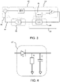
- Figure 3 shows the amplitude detection circuit of the invention.
- the signal source is again represented as an oscillator 40.
- the oscillator is not free running, but is an amplitude controlled oscillator, having an amplitude control input 41.
- the detected signal is provided to a amplitude detector 42 again functioning as an amplitude demodulator.
- the amplitude detector 42 is used to measure the imaginary part of the complex reflected inductance.
- Figure 4 shows an example of the amplitude detection circuit, implemented as a peak detector circuit.
- Measuring the imaginary part of the complex reflected inductance involves demodulating an amplitude modulated signal, i.e. the oscillator tank swing is modulated by the physiological signal from the body.
- Amplitude demodulating circuits are well known and Figure 4 shows a most simple example in the form of a peak detector consisting of a diode D and a low-pass filter R,C.
- the RC values are chosen such that RF ripple from the carrier is minimized but the filter can react fast enough to changes in the physiological signal.
- the amplitude detector' block is thus implemented by an amplitude demodulator.
- the measured amplitude signal is provided to a low-resolution ADC 44, for example a 1 bit quantizer.
- the quantizer compares its input signal to a reference 45 as part of the quantization process. This uses much less power than a full-resolution ADC, because it has fewer powered electronic sub-components.
- a counter 46 (a digital integrator) adds up the individual results of the quantizer.
- the output of the counter 46 is the measurement output 50, and it is also applied to a digital to analog converter 48 so that an analog control signal is applied to the oscillator 40, thereby closing the negative feedback loop.
- the digital to analog converter 48 is one part of a feedback controller.
- the analog signal 41 interacts with the oscillator circuit, and a part of the oscillator circuit thus also functions as part of the feedback controller. Options for implementing the feedback control are discussed below.
- the negative feedback loop controls the amplitude to remain at a constant value, dependent on the reference 45 applied within the analog to digital converter 44.
- the analog to digital converter may, for example, comprise an array of switchable resistors.
- the ADC 44 when implemented as a 1-bit quantizer just determines whether the peak detector output is above or below the reference value. In order to obtain a peak detector output at the same level as the reference, the oscillator amplitude needs to be adjusted. The amount of adjustment is controlled by the counter (digital integrator) which will count up or down by one based on the ADC output until the reference value is reached. In case of a tri-state quantizer instead of a 1-bit quantizer, this results in the quantizer output to be 0. A 1-bit quantizer will keep toggling between 0 and 1 with the amplitude detector output around the reference level.
- the circuit avoids losing information contained in the amplitude measurement, for example as would be the case if the oscillator amplitude is limited but without a control loop.
- EMC is achieved by using the integrated digital result of the amplitude measurement to control the amplitude of the oscillator and thereby limit the amplitude of the oscillator signal.
- This amplitude limiting function of the circuit addresses the issue of a high radiated power by the loop antenna and decreased signal to noise ratio (SNR) when the sensor is applied to the body.
- SNR signal to noise ratio
- the measured amplitude itself thus no longer contains the information of the biometric signal being measured; this information has been transferred to the feedback control signal which thus defines the output value of the circuit (but still in the digital domain).
- the ADC 44 may be a 1 bit quantizer as mentioned above.
- the ADC 44 may instead be a 2-bit quantizer, or a multi-bit quantizer.
- the ADC 44 may instead be a 1-trit quantizer or a multi-trit quantizer.
- the quantizer in all cases has a resolution lower than the output resolution, i.e. the number of levels of the output value 50 as explained above.
- the ADC 44 determines (at least) whether the oscillator amplitude is above or below the reference level. Accordingly, the counter 46 will increase or decrease its value in order to increase or decrease the oscillator amplitude.
- the quantizer electronics is now much less complex and no longer requires a large dynamic range (only some dynamic range is needed around the reference level).
- the measurement output is in this way derived from multiple operations of the quantizer and hence built up over time.
- the loop frequency of the circuit is higher than the highest frequency to be tracked of the amplitude being measured.
- the loop frequency of the circuit depends on the resolution of the counter and hence digital output. A higher resolution means that the step of one count is smaller. In order to adjust the oscillator such that the amplitude detector is always at the reference level, faster adjustment is needed with smaller steps. If, for example, a triangular waveform is to be followed with a frequency of 1 Hz covering 100 LSB, adjustments will need to be made at 200 Hz (counting up 100 times and counting down 100 times). If the same signal is to be tracked with a resolution of 10 LSB, the loop frequency can be lower at 20 Hz.
- the minimum frequency of the loop is determined by the steepest part of the derivative of the input signal.
- Using a multi-bit quantizer as the ADC 44 enables determination of whether the amplitude is one or more LSBs from the reference, and in this way the counter can be adjusted with adjustments larger than 1, catching up more quickly than with a 1-bit quantizer.
- the exact frequency of the loop depends on the resolution and bandwidth of the output signal, allowed error and the resolution of the quantizer.
- the loop frequency will always be higher than the output bandwidth.
- the loop frequency is typically in the range of 1-10kHz for a realistic system.
- the bandwidth of the signal to be detected is typically 33 Hz.
- This large frequency margin allows the required output resolution to be formed by an iterative integration process.
- the quantizer delivers difference outputs successively until the feedback loop has adapted to the new input signal.
- the required change in the oscillator control signal 41 is recorded, and this corresponds to the measured amplitude.
- the counter 46 only consumes power when it is switching (i.e. increasing or decreasing its output value) when implemented using CMOS logic, making this power efficient as well.
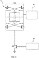
- the amplitude of the oscillator 40 can be controlled in various ways.
- Figure 5 shows an example of the oscillator circuit 40 with the output provided to the amplitude detector 42 (of Figure 3 ) and the feedback signal received from the digital to analog converter 48 (of Figure 3 ).
- the oscillator circuit 40 is a well known cross-coupled CMOS oscillator, comprising two parallel circuit branches with cross-coupled pull up transistors M1, M2 and cross-coupled pull down transistors M3, M4.
- the oscillator tank is a parallel LC circuit connected between the branches.
- the resistance R is thus not normally the result of a physically present component in the circuit, but such a resistor may be used to introduce a deliberate switchable loss (as discussed below).
- the tank voltage swing is measured using the amplitude detector 42, e.g. a peak detector as explained above.
- a bias current drawn from the oscillator circuit is controlled by a tail transistor M5.
- the bias current is directly related to the tank voltage swing.
- the digital to analog converter 48 can be implemented in different ways to control the bias current. This could be, but is not limited to, a current mirror with adjustable current or a voltage DAC controlling the gate-source voltage of the tail transistor.
- an adjustable resistor may be used, controlled by the output of the counter.
- the amplitude control is achieved by a voltage digital to analogue converter 48 controlling the gate-source voltage of the tail transistor M5.
- the loop impedance can be expressed in terms of inductance (L), capacitance (C) and resistance (R).
- L inductance
- C capacitance
- R resistance
- the series losses of the inductor increase when applied to the body, which means the equivalent parallel resistance decreases compared to when it is in free space, and it also varies with the physiological signal that is being measured.
- the resistance R directly influences the tank voltage swing of the oscillator. Therefore an option is to control the amplitude by controlling the resistance of the loop. Additional resistors in series or parallel to the loop can be switched on or off in such a way that the total loop resistance is always the same. This would mean that for the highest imaginary reflected inductance value, no or little extra resistance is added, but in free space when the imaginary part of the reflected impedance is low, more resistance is added to end up with the same total resistance.
- the amount of extra resistance needed is then a measure for the physiological signal that is being measured. Having a constant loop resistance keeps the tank voltage swing, and therefore the current through the loop, at a constant level, reducing the radiated magnetic field making it EMC compliant.
- Another example is to introduce controllable losses to the source of one or more of the oscillator transistors.
- the amplitude is typically controlled in an analog manner, hence the need for the digital to analog converter 48.
- the output connects to the oscillator tank for example to increase the damping in free space, or is connected to a current mirror to control the bias current of the oscillator, as mentioned above.
- a frequency of the electromagnetic excitation signals is for example from 30 MHz to 1000 MHz. Other suitable ranges are 100 MHz to 1000 MHz, 30 MHz to 500 MHz and 100 MHz to 500 MHz.
- the measurement output is typically displayed for an end-user which could be a clinician, nurse, or the patient him/herself, or a healthy consumer for example in sleep and sport applications.
- the system may in particular be a vital sign sensing system.
- Vital signs may include for instance heart rate, pulse rate, breathing capacity, breathing rate, stroke volume, stroke volume variations, cardiac output, or aortic or arterial pulse height/pressure/diameter modulations.
- a signal processing means may be provided for processing the output values overtime to derive the desired one or more physiological parameters.
- the invention is of interest for patient monitoring applications, telemetry, and spot-check monitoring. It may be integrated into a wearable system, such as a chest patch or a wrist-worn device or it may be part of a mattress based monitoring system.
- the invention is for example of particular interest for neonatal monitoring, sleep monitoring, or obstetrical monitoring.
- a single processor or other unit may fulfill the functions of several items recited in the claims.
- a computer program may be stored/distributed on a suitable medium, such as an optical storage medium or a solid-state medium supplied together with or as part of other hardware, but may also be distributed in other forms, such as via the Internet or other wired or wireless telecommunication systems.
- a suitable medium such as an optical storage medium or a solid-state medium supplied together with or as part of other hardware, but may also be distributed in other forms, such as via the Internet or other wired or wireless telecommunication systems.
Landscapes
- Health & Medical Sciences (AREA)
- Life Sciences & Earth Sciences (AREA)
- Engineering & Computer Science (AREA)
- General Health & Medical Sciences (AREA)
- Medical Informatics (AREA)
- Veterinary Medicine (AREA)
- Public Health (AREA)
- Animal Behavior & Ethology (AREA)
- Physics & Mathematics (AREA)
- Signal Processing (AREA)
- Biophysics (AREA)
- Pathology (AREA)
- Biomedical Technology (AREA)
- Heart & Thoracic Surgery (AREA)
- Surgery (AREA)
- Molecular Biology (AREA)
- Artificial Intelligence (AREA)
- Psychiatry (AREA)
- Power Engineering (AREA)
- Physiology (AREA)
- Computer Vision & Pattern Recognition (AREA)
- Nuclear Medicine, Radiotherapy & Molecular Imaging (AREA)
- Radiology & Medical Imaging (AREA)
- Measurement And Recording Of Electrical Phenomena And Electrical Characteristics Of The Living Body (AREA)
- Measuring Pulse, Heart Rate, Blood Pressure Or Blood Flow (AREA)
- Measurement Of The Respiration, Hearing Ability, Form, And Blood Characteristics Of Living Organisms (AREA)
Priority Applications (6)
| Application Number | Priority Date | Filing Date | Title |
|---|---|---|---|
| EP20211050.8A EP4008247A1 (de) | 2020-12-01 | 2020-12-01 | Induktives sensorsystem zur messung elektromagnetischer signale aus einem körper |
| US18/039,586 US20240000334A1 (en) | 2020-12-01 | 2021-11-22 | Inductive sensing system for sensing electromagnetic signals from a body |
| EP21814785.8A EP4287940B1 (de) | 2020-12-01 | 2021-11-22 | Induktives sensorsystem zur messung elektromagnetischer signale aus einem körper |
| JP2023532495A JP7564953B2 (ja) | 2020-12-01 | 2021-11-22 | 体からの電磁信号を検知する誘導検知システム |
| CN202180081014.9A CN116963660A (zh) | 2020-12-01 | 2021-11-22 | 用于感测来自身体的电磁信号的感应感测系统 |
| PCT/EP2021/082412 WO2022117377A1 (en) | 2020-12-01 | 2021-11-22 | Inductive sensing system for sensing electromagnetic signals from a body |
Applications Claiming Priority (1)
| Application Number | Priority Date | Filing Date | Title |
|---|---|---|---|
| EP20211050.8A EP4008247A1 (de) | 2020-12-01 | 2020-12-01 | Induktives sensorsystem zur messung elektromagnetischer signale aus einem körper |
Publications (1)
| Publication Number | Publication Date |
|---|---|
| EP4008247A1 true EP4008247A1 (de) | 2022-06-08 |
Family
ID=73694748
Family Applications (2)
| Application Number | Title | Priority Date | Filing Date |
|---|---|---|---|
| EP20211050.8A Withdrawn EP4008247A1 (de) | 2020-12-01 | 2020-12-01 | Induktives sensorsystem zur messung elektromagnetischer signale aus einem körper |
| EP21814785.8A Active EP4287940B1 (de) | 2020-12-01 | 2021-11-22 | Induktives sensorsystem zur messung elektromagnetischer signale aus einem körper |
Family Applications After (1)
| Application Number | Title | Priority Date | Filing Date |
|---|---|---|---|
| EP21814785.8A Active EP4287940B1 (de) | 2020-12-01 | 2021-11-22 | Induktives sensorsystem zur messung elektromagnetischer signale aus einem körper |
Country Status (5)
| Country | Link |
|---|---|
| US (1) | US20240000334A1 (de) |
| EP (2) | EP4008247A1 (de) |
| JP (1) | JP7564953B2 (de) |
| CN (1) | CN116963660A (de) |
| WO (1) | WO2022117377A1 (de) |
Citations (2)
| Publication number | Priority date | Publication date | Assignee | Title |
|---|---|---|---|---|
| US20140095102A1 (en) * | 2012-09-28 | 2014-04-03 | General Electric Company | Systems and methods for monitoring sensors |
| WO2018127482A1 (en) | 2017-01-09 | 2018-07-12 | Koninklijke Philips N.V. | Inductive sensing system for sensing electromagnetic signals from a body |
Family Cites Families (12)
| Publication number | Priority date | Publication date | Assignee | Title |
|---|---|---|---|---|
| US5027306A (en) * | 1989-05-12 | 1991-06-25 | Dattorro Jon C | Decimation filter as for a sigma-delta analog-to-digital converter |
| US5329282A (en) * | 1992-03-02 | 1994-07-12 | Motorola, Inc. | Multi-bit sigma-delta analog-to-digital converter with reduced sensitivity to DAC nonlinearities |
| US7811234B2 (en) * | 2002-08-01 | 2010-10-12 | California Institute Of Technology | Remote-sensing method and device |
| US7126435B2 (en) * | 2003-09-23 | 2006-10-24 | Rambus Inc. | Voltage controlled oscillator amplitude control circuit |
| US8436758B2 (en) * | 2010-03-22 | 2013-05-07 | Decawave Ltd. | Adaptive ternary A/D converter for use in an ultra-wideband communication system |
| US10548495B2 (en) * | 2015-04-01 | 2020-02-04 | Xtrava Inc. | Contactless or non-invasive physical properties measurement instrument using eddy current-reduced high Q resonant circuit probe |
| US9515605B1 (en) * | 2015-08-25 | 2016-12-06 | Microsemi Storage Solutions (U.S.), Inc. | Variable gain electro-mechanical oscillator and method for starting balanced oscillations |
| US9813023B2 (en) * | 2015-12-16 | 2017-11-07 | Silicon Laboratories Inc. | Common-mode impedance network for reducing sensitivity in oscillators |
| CN107174246A (zh) * | 2017-04-24 | 2017-09-19 | 东北大学 | 一种基于心肺信号的人体状态监测系统及方法 |
| EP3591839B1 (de) * | 2018-07-06 | 2021-01-20 | Stichting IMEC Nederland | Amplitudenkalibrierte oszillatorvorrichtung |
| EP3669774A1 (de) * | 2018-12-18 | 2020-06-24 | Koninklijke Philips N.V. | System und verfahren zur induktiven messung |
| JP7407598B2 (ja) * | 2019-03-12 | 2024-01-04 | キヤノンメディカルシステムズ株式会社 | 生体情報モニタ装置及び磁気共鳴イメージング装置 |
-
2020
- 2020-12-01 EP EP20211050.8A patent/EP4008247A1/de not_active Withdrawn
-
2021
- 2021-11-22 WO PCT/EP2021/082412 patent/WO2022117377A1/en not_active Ceased
- 2021-11-22 CN CN202180081014.9A patent/CN116963660A/zh active Pending
- 2021-11-22 JP JP2023532495A patent/JP7564953B2/ja active Active
- 2021-11-22 US US18/039,586 patent/US20240000334A1/en active Pending
- 2021-11-22 EP EP21814785.8A patent/EP4287940B1/de active Active
Patent Citations (2)
| Publication number | Priority date | Publication date | Assignee | Title |
|---|---|---|---|---|
| US20140095102A1 (en) * | 2012-09-28 | 2014-04-03 | General Electric Company | Systems and methods for monitoring sensors |
| WO2018127482A1 (en) | 2017-01-09 | 2018-07-12 | Koninklijke Philips N.V. | Inductive sensing system for sensing electromagnetic signals from a body |
Also Published As
| Publication number | Publication date |
|---|---|
| CN116963660A (zh) | 2023-10-27 |
| US20240000334A1 (en) | 2024-01-04 |
| EP4287940B1 (de) | 2024-06-26 |
| JP7564953B2 (ja) | 2024-10-09 |
| WO2022117377A1 (en) | 2022-06-09 |
| EP4287940A1 (de) | 2023-12-13 |
| JP2023552335A (ja) | 2023-12-15 |
Similar Documents
| Publication | Publication Date | Title |
|---|---|---|
| CN110167441B (zh) | 用于感测来自身体的电磁信号的电感感测系统 | |
| US12023499B2 (en) | Methods and systems for measuring tissue impedance and monitoring PVD treatment using neuro-implants with improved ultrasound powering | |
| CN110996787B (zh) | 用于通过频率调谐和阻抗相位和/或幅度变化的分析来动态聚焦于心脏和/或肺的系统和方法 | |
| Pichorim et al. | A novel method to read remotely resonant passive sensors in biotelemetric systems | |
| US20170042437A1 (en) | Contactless or non-invasive physical properties measurement instrument using eddy current-reduced high q resonant circuit probe | |
| Yu et al. | A miniature batteryless bioelectronic implant using one magnetoelectric transducer for wireless powering and PWM backscatter communication | |
| EP4287940B1 (de) | Induktives sensorsystem zur messung elektromagnetischer signale aus einem körper | |
| CN112654287B (zh) | 感应式感测装置及方法 | |
| CN113453616B (zh) | 感应式感测系统和方法 | |
| US20230172473A1 (en) | Wearable bio-electromagnetic sensor and method of measuring physiological parameters of a body tissue | |
| Guardo et al. | Contactless measurement of thoracic conductivity changes by magnetic induction | |
| TW202442186A (zh) | 心肺狀態量測裝置 | |
| CN210249824U (zh) | 一种心率贴和心率监测仪 | |
| RU2795044C2 (ru) | Система индуктивного считывания электромагнитных сигналов от тела | |
| CN109998516A (zh) | 一种心率贴和心率监测仪 | |
| CN114760913A (zh) | 感应式感测系统和方法 | |
| Hennig et al. | Sensor transponder system for cardiovascular diseases |
Legal Events
| Date | Code | Title | Description |
|---|---|---|---|
| PUAI | Public reference made under article 153(3) epc to a published international application that has entered the european phase |
Free format text: ORIGINAL CODE: 0009012 |
|
| STAA | Information on the status of an ep patent application or granted ep patent |
Free format text: STATUS: THE APPLICATION HAS BEEN PUBLISHED |
|
| AK | Designated contracting states |
Kind code of ref document: A1 Designated state(s): AL AT BE BG CH CY CZ DE DK EE ES FI FR GB GR HR HU IE IS IT LI LT LU LV MC MK MT NL NO PL PT RO RS SE SI SK SM TR |
|
| STAA | Information on the status of an ep patent application or granted ep patent |
Free format text: STATUS: THE APPLICATION IS DEEMED TO BE WITHDRAWN |
|
| 18D | Application deemed to be withdrawn |
Effective date: 20221209 |