EP4008274B1 - Minimal invasive chirurgische zielführungen - Google Patents
Minimal invasive chirurgische zielführungen Download PDFInfo
- Publication number
- EP4008274B1 EP4008274B1 EP21212200.6A EP21212200A EP4008274B1 EP 4008274 B1 EP4008274 B1 EP 4008274B1 EP 21212200 A EP21212200 A EP 21212200A EP 4008274 B1 EP4008274 B1 EP 4008274B1
- Authority
- EP
- European Patent Office
- Prior art keywords
- holes
- plate
- bone
- block
- bone plate
- Prior art date
- Legal status (The legal status is an assumption and is not a legal conclusion. Google has not performed a legal analysis and makes no representation as to the accuracy of the status listed.)
- Active
Links
Images





Classifications
-
- A—HUMAN NECESSITIES
- A61—MEDICAL OR VETERINARY SCIENCE; HYGIENE
- A61B—DIAGNOSIS; SURGERY; IDENTIFICATION
- A61B17/00—Surgical instruments, devices or methods
- A61B17/16—Instruments for performing osteoclasis; Drills or chisels for bones; Trepans
- A61B17/17—Guides or aligning means for drills, mills, pins or wires
- A61B17/1728—Guides or aligning means for drills, mills, pins or wires for holes for bone plates or plate screws
-
- A—HUMAN NECESSITIES
- A61—MEDICAL OR VETERINARY SCIENCE; HYGIENE
- A61B—DIAGNOSIS; SURGERY; IDENTIFICATION
- A61B17/00—Surgical instruments, devices or methods
- A61B17/56—Surgical instruments or methods for treatment of bones or joints; Devices specially adapted therefor
- A61B17/58—Surgical instruments or methods for treatment of bones or joints; Devices specially adapted therefor for osteosynthesis, e.g. bone plates, screws or setting implements
- A61B17/68—Internal fixation devices, including fasteners and spinal fixators, even if a part thereof projects from the skin
- A61B17/80—Cortical plates, i.e. bone plates; Instruments for holding or positioning cortical plates, or for compressing bones attached to cortical plates
- A61B17/8052—Cortical plates, i.e. bone plates; Instruments for holding or positioning cortical plates, or for compressing bones attached to cortical plates immobilised relative to screws by interlocking form of the heads and plate holes, e.g. conical or threaded
- A61B17/8057—Cortical plates, i.e. bone plates; Instruments for holding or positioning cortical plates, or for compressing bones attached to cortical plates immobilised relative to screws by interlocking form of the heads and plate holes, e.g. conical or threaded the interlocking form comprising a thread
-
- A—HUMAN NECESSITIES
- A61—MEDICAL OR VETERINARY SCIENCE; HYGIENE
- A61B—DIAGNOSIS; SURGERY; IDENTIFICATION
- A61B17/00—Surgical instruments, devices or methods
- A61B17/56—Surgical instruments or methods for treatment of bones or joints; Devices specially adapted therefor
- A61B17/58—Surgical instruments or methods for treatment of bones or joints; Devices specially adapted therefor for osteosynthesis, e.g. bone plates, screws or setting implements
- A61B17/68—Internal fixation devices, including fasteners and spinal fixators, even if a part thereof projects from the skin
- A61B17/80—Cortical plates, i.e. bone plates; Instruments for holding or positioning cortical plates, or for compressing bones attached to cortical plates
- A61B17/808—Instruments for holding or positioning bone plates, or for adjusting screw-to-plate locking mechanisms
-
- A—HUMAN NECESSITIES
- A61—MEDICAL OR VETERINARY SCIENCE; HYGIENE
- A61B—DIAGNOSIS; SURGERY; IDENTIFICATION
- A61B17/00—Surgical instruments, devices or methods
- A61B17/56—Surgical instruments or methods for treatment of bones or joints; Devices specially adapted therefor
- A61B17/58—Surgical instruments or methods for treatment of bones or joints; Devices specially adapted therefor for osteosynthesis, e.g. bone plates, screws or setting implements
- A61B17/68—Internal fixation devices, including fasteners and spinal fixators, even if a part thereof projects from the skin
- A61B17/80—Cortical plates, i.e. bone plates; Instruments for holding or positioning cortical plates, or for compressing bones attached to cortical plates
- A61B17/8061—Cortical plates, i.e. bone plates; Instruments for holding or positioning cortical plates, or for compressing bones attached to cortical plates specially adapted for particular bones
-
- A—HUMAN NECESSITIES
- A61—MEDICAL OR VETERINARY SCIENCE; HYGIENE
- A61B—DIAGNOSIS; SURGERY; IDENTIFICATION
- A61B17/00—Surgical instruments, devices or methods
- A61B2017/0042—Surgical instruments, devices or methods with special provisions for gripping
- A61B2017/00424—Surgical instruments, devices or methods with special provisions for gripping ergonomic, e.g. fitting in fist
Definitions
- targeting guides are typically used.
- a targeting guide that provides accurate placement of the screws while accommodating more than one plate configuration, thereby advantageously reducing the amount of tools required for a given surgery.
- the targeting guide is configured as a targeting block and may be part of a targeting system for accurately implanting bone screws within a bone plate.
- the block has different sides extending that have different patterns corresponding to holes of a different bone plate.
- the holes of each side of the targeting block align axially with holes of the respective bone plate, based on the side of the targeting block that is utilized (facing the user).
- Opposing upper and lower sides of the block are designed to correspond to left and right versions of a bone plate of a first size and/or shape.
- the opposing lateral sides of the block are designed to correspond to left and right versions of a bone plate of a second size and/or shape. Accordingly, the targeting block is designed to accurately place screws within four different plates.
- connection hole may have a different shape than each of the first holes and second holes.
- Each connection hole may be positioned at a proximal end of the block.
- One of the upper side and the lower side of the body may correspond to a left femur bone plate and the other side of the upper side and the lower side may correspond to a right femur plate.
- the system may include a monoaxial sleeve having a proximal end received within any one of the holes of the targeting guide and a distal end received within an axially aligned hole of the bone plate.
- the first bone plate and the second bone plate each may have an oblong hole and the targeting guide has a connection hole.
- the system may further include a support having a distal end configured to attach to the oblong hole of the first plate and of the second plate and a proximal end configured to attach to the connection holes of the targeting guide.
- Yet another aspect not forming part of the present invention includes a method that includes the steps of selecting between a first bone plate and a second bone plate, the first and second bone plates having different patterns of bone plate holes; selecting between a plurality of sides of a targeting guide based on the selected bone plate; attaching the targeting guide to the selected bone plate.
- the present invention generally relates to a targeting guide to be used in conjunction with a bone plate and screws for monoaxial screw placement of the bone plate on the bone.
- proximal refers to the end of the bone plate or targeting block that is closer to the heart
- distal refers to the end of the bone plate or targeting block that is further from the heart.
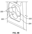
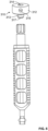
- Figs. 1-14 depict a targeting guide system 100 including a targeting block 200, supports or handles 300, and instrumentation 400.
- Targeting guide system 100 is designed to facilitate the accurate placement of screws within holes of bone plates and into engagement with the bone.
- the trajectory of the bone screw placement may be monoaxial, or along one single axis, and in other instances, it is contemplated, that the trajectory of the bone screw placement may be polyaxial, along more than one axis.
- the system is configured to correspond to any type of bone plate, and is particularly useful where at least two bone plates having different lengths from one another and/or left and right plate versions are included. The different cooperations between the guide and the plates being achieved through rotation of the targeting guide, for instance, with different bone plate sizes and/or shapes being engageable upon 90 degrees rotation of the guide, and the right-left configuration being engageable upon 180 degrees rotation.
- the targeting systems disclosed herein are designed for use on any bones.
- the targeting guide blocks are configured for connection to any type of plate.
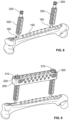
- Fig. 2 shows plates 150, 150' each including a plurality of screw holes 170, 170' for polyaxial or monoaxial placement of screws within the holes.
- Each hole 170 includes a central axis extending in the direction from the upper and lower surfaces of the plate. Plates with such holes are described in further detail in U.S. Patent Publication No. 2019/0269445, entitled Bone Plates and Associated Screws, filed on March 1, 2019 .
- Plate 150 and plate 150' are substantially similar except that plate 150' has a greater length than plate 150'. As a result, plate 150 and plate 150' have a different arrangement of holes 170, 170' due to the difference in length.
- plate 150 has twelve holes 170 positioned between oblong holes 160 and arranged in six pairs of diagonal holes; whereas, plate 150' has thirteen holes 170' positioned between oblong holes 160' with six pairs of diagonal holes and an additional hole.
- targeting guide system 100 facilitates accurate insertion of the screws within holes 170, 170' of plates 150, 150'.
- plates 150, 150' each include at least one oblong hole 160, 160' for connection of a support or handle, as will be discussed in further detail below.
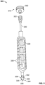
- Handle 300 which facilitates the connection of block 200 to a bone plate 150.
- Handle 300 includes wheel 310, shaft 320 and grip 330.
- Handle 330 extends between proximal end 302, closest to the operator in use, which connects to block 200, and distal end 304 which connects to oblong hole 160 of bone plate 150.
- Tissue protection sleeve 410 includes an outer flange 412 at a proximal end thereof to be received within holes 216, 218 of block 200 and enable tissue protection sleeve to be locked within the holes to prevent movement.
- tissue protection sleeve 410 and holes 216, 218 are sized to allow movement of the tissue protection sleeve within the hole at a plurality of axes, angled relative to the central axis of the holes 216, 218 to accommodate placement of the screws at a plurality of axes relative to holes 216, 218 and bone plate holes 170.
- Figs. 8-13 show targeting guide system 100 in use on a femur bone.
- handles 300 are each attached to oblong holes 160 of the bone plate 150 at engagement portion 332 of grip 330.
- Shaft 320 is positioned within grip 330 and tightened to establish a solid link between the plate and the shaft-grip assembly, shown in Fig. 8 .
- This step is performed twice to attach the two handles to the two oblong holes 160 of the plate 150.
- the user chooses the appropriate block 200 as well as the appropriate sides of the block, i.e. upper and lower sides or lateral sides, which will be used as the aiming guide for the bone plate holes.
- the block 200 can be rotated 90 degrees and based on whether the plate is the left side or the right of the body, the block 200 can be rotated 180 degrees.
- Both supports or handles 300 are connected and the targeting block 200 is positioned above and aligned with the bone plate 150 such that respective holes 216 (or 218 depending on the position of the block) align with the respective hole 170 of plate 150.
- respective holes 216 or 218 depending on the position of the block align with the respective hole 170 of plate 150.
- the central axis of a hole 216 is coaxial with the corresponding central axis of the respective hole 170 of plate 150.
- Trocar 430 is inserted into drill sleeve 420 and the assembly is inserted into tissue protection sleeve 410, which is a monoaxial sleeve. As shown in Fig. 11 , tissue protection sleeve 410 is then placed within a hole 216 (or 218 depending upon which side of the block is utilized, but for simplicity only hole 216 will be used for the description of use) and the corresponding hole 170 of plate 150. Tissue protection sleeve 410 is rotated to lock the tissue protection sleeve into hole 216 and then guided into hole 170 of the bone plate.
- Trocar 430 is then removed in order to begin drilling of the screw hole into bone.
- Figs. 12 and 13 show drill sleeve 420 and tissue protection sleeve 410 within hole 216 of block 200.
- Drill bit 470 is positioned within drill sleeve 420 and torqued to form the hole into which a locking or non-locking screw will be implanted.
- Drill sleeve 420 is removed prior to tapping or screw insertion.
- a screwdriver, with screw attached, shown in Fig. 14 is placed within tissue protection sleeve and to fix the screw in the bone along the axis defined by holes 216 of block 200. In this manner, the screw is positioned along the monoaxial trajectory of the hole 216.
- the sleeve assembly can be moved to various holes 216 to implant a plurality of screws through block 200 and into engagement with bone plate 150 and the bone to provide fixation of the bone plate to the bone.
- Each holes 216 of block 200 allows for accurate monoaxial screw placement of the locking or non-locking screws within bone plate 150.
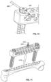
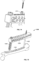
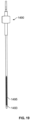
- Figs. 15-17 show targeting guide system 1100 including targeting block 1200, bone plate 1150, handle 1300 and instrumentation 1400.
- Like reference numerals refer to like elements in this embodiment, but with numbers in the 1000 series, and the differences will between systems 100 and 1100 will be discussed.
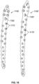
- System 1100 is identical to system 100 in many respects, except that system 1100 is designed to be used in conjunction with proximal and distal plates having one oblong hole 1160, as shown in Fig. 16 . Therefore, the system includes one handle 1300 for connection to the one oblong hole 1160 of the plate 1150.
Landscapes
- Health & Medical Sciences (AREA)
- Orthopedic Medicine & Surgery (AREA)
- Surgery (AREA)
- Life Sciences & Earth Sciences (AREA)
- Heart & Thoracic Surgery (AREA)
- Veterinary Medicine (AREA)
- Engineering & Computer Science (AREA)
- Biomedical Technology (AREA)
- Nuclear Medicine, Radiotherapy & Molecular Imaging (AREA)
- Medical Informatics (AREA)
- Molecular Biology (AREA)
- Animal Behavior & Ethology (AREA)
- General Health & Medical Sciences (AREA)
- Public Health (AREA)
- Dentistry (AREA)
- Oral & Maxillofacial Surgery (AREA)
- Neurology (AREA)
- Surgical Instruments (AREA)
Claims (13)
- Zielführung für eine Knochenplatte (150, 150'), die Folgendes umfasst:
einen Körper (200, 1200) in der Gestalt eines Blockes, wobei der Körper eine Oberseite (212, 1212) und eine gegenüberliegenden Unterseite (214, 1214), eine erste laterale Seite (208, 1208) und eine zweite gegenüberliegende laterale Seite (210, 1210) aufweist, wobei jede der lateralen Seiten (208, 210, 1208, 1210) die Oberseite (212, 1212) und die Unterseite (214, 1214) verbindet, eine erste Mehrzahl von Löchern (216, 1216), die sich durch die Ober- und die Unterseite (212, 214, 1212, 1214) erstreckt und in einem ersten Muster angeordnet ist, das so konfiguriert ist, dass es mit einem ersten Muster von Löchern (170, 1170) einer ersten Knochenplatte (150, 1150) ausgerichtet ist, eine zweite Mehrzahl von Löchern (218, 1218), die sich durch die erste und die zweite laterale Seite (208, 210, 1208, 1210) erstreckt und in einem unterschiedlichen zweiten Muster angeordnet ist, das so konfiguriert ist, dass es mit einem zweiten Muster von Löchern (170', 1170') einer zweiten Knochenplatte (150', 1150') ausgerichtet ist, die sich von der ersten Knochenplatte (150, 1150) unterscheidet. - Zielführung nach Anspruch 1, wobei die erste Mehrzahl von Löchern (216, 1216) und die zweite Mehrzahl von Löchern (218, 1218) zur Aufnahme von Knochenschrauben durch sie hindurch konfiguriert sind.
- Zielführung nach Anspruch 2, wobei die erste Mehrzahl von Löchern (216, 1216) und die zweite Mehrzahl von Löchern (218, 1218) so konfiguriert sind, dass sie eine monoaxiale Hülse aufnehmen.
- Zielführung nach einem der vorhergehenden Ansprüche, wobei das erste Muster Paare von diagonalen Löchern (216, 1216) enthält.
- Zielführung nach einem der vorhergehenden Ansprüche, insbesondere nach Anspruch 4, wobei das zweite Muster Paare von diagonalen Löchern (218, 1218) umfasst.
- Zielführung nach einem der vorhergehenden Ansprüche, wobei das erste Muster weniger Löcher (216, 1216) enthält als das zweite Muster.
- Zielführung nach einem der vorhergehenden Ansprüche, wobei die zweite Knochenplatte (150', 1150') länger ist als die erste Knochenplatte (150, 1150).
- Zielführung nach einem der vorhergehenden Ansprüche, wobei der Körper (200, 1200) rechteckig ist.
- Zielführung nach einem der vorhergehenden Ansprüche, wobei der Körper (200, 1200) weiterhin mindestens ein Verbindungsloch (220, 1220) an jeder der oberen und unteren Seiten (212, 214, 1212, 1214) und der ersten und zweiten lateralen Seiten (208, 210, 1208, 1210) des Körpers (200, 1200) aufweist.
- Zielführung nach Anspruch 9, wobei das Verbindungsloch (220, 1220) eine andere Form hat als jedes der ersten Löcher (216, 1216) und zweiten Löcher (218, 1218).
- Zielführung nach Anspruch 9 oder 10, wobei jedes Verbindungsloch (220, 1220) an einem proximalen Ende (202, 1202) des Körpers (200, 1200) angeordnet ist.
- Zielführung nach einem der vorhergehenden Ansprüche, wobei eine der Oberseite (212, 1212) und der Unterseite (214, 1214) des Körpers (200, 1200) einer linken Oberschenkelknochenplatte entspricht und die andere Seite der Oberseite (212, 1212) und der Unterseite (214, 1214) einer rechten Oberschenkelknochenplatte entspricht.
- Zielführung nach einem der vorhergehenden Ansprüche, wobei die Zielführung so konfiguriert ist, dass sie an der ersten Knochenplatte (150, 1150) und an der zweiten Knochenplatte (150', 1150') angebracht werden kann, wobei, wenn die Zielführung an der ersten Knochenplatte (150, 1150) angebracht ist, die erste Mehrzahl von Löchern (216, 1216) mit dem ersten Muster von Löchern (170, 1170) einer ersten Knochenplatte (150, 1150) ausgerichtet ist und, wenn die Zielführung an der zweiten Knochenplatte (150', 1150') angebracht ist, die zweite Vielzahl von Löchern (218, 1218) mit dem zweiten Muster von Löchern (170', 1170') der zweiten Knochenplatte (150', 1150') ausgerichtet ist.
Applications Claiming Priority (1)
| Application Number | Priority Date | Filing Date | Title |
|---|---|---|---|
| US17/110,562 US11432832B2 (en) | 2020-12-03 | 2020-12-03 | Minimally invasive surgery targeting guides and methods of use |
Publications (2)
| Publication Number | Publication Date |
|---|---|
| EP4008274A1 EP4008274A1 (de) | 2022-06-08 |
| EP4008274B1 true EP4008274B1 (de) | 2025-04-09 |
Family
ID=78821186
Family Applications (1)
| Application Number | Title | Priority Date | Filing Date |
|---|---|---|---|
| EP21212200.6A Active EP4008274B1 (de) | 2020-12-03 | 2021-12-03 | Minimal invasive chirurgische zielführungen |
Country Status (2)
| Country | Link |
|---|---|
| US (3) | US11432832B2 (de) |
| EP (1) | EP4008274B1 (de) |
Families Citing this family (3)
| Publication number | Priority date | Publication date | Assignee | Title |
|---|---|---|---|---|
| US12279795B2 (en) * | 2017-09-13 | 2025-04-22 | Globus Medical, Inc. | Bone stabilization systems |
| US11432832B2 (en) * | 2020-12-03 | 2022-09-06 | Stryker European Operations Limited | Minimally invasive surgery targeting guides and methods of use |
| US20250009366A1 (en) | 2023-07-06 | 2025-01-09 | Stryker European Operations Limited | Modular Aiming Block for Targeting System |
Family Cites Families (22)
| Publication number | Priority date | Publication date | Assignee | Title |
|---|---|---|---|---|
| US20050049594A1 (en) * | 2001-04-20 | 2005-03-03 | Wack Michael A. | Dual locking plate and associated method |
| US20060173458A1 (en) | 2004-10-07 | 2006-08-03 | Micah Forstein | Bone fracture fixation system |
| US8043297B2 (en) | 2004-11-03 | 2011-10-25 | Synthes Usa, Llc | Aiming arm for bone plates |
| US8100952B2 (en) * | 2005-12-22 | 2012-01-24 | Anthem Orthopaedics Llc | Drug delivering bone plate and method and targeting device for use therewith |
| US8328809B2 (en) | 2010-01-07 | 2012-12-11 | Zimmer, Inc. | Bone plate fixation system |
| US8641741B2 (en) | 2010-10-13 | 2014-02-04 | Stryker Leibinger Gmbh & Co. Kg | Bone plate aiming block |
| WO2012158253A1 (en) | 2011-05-18 | 2012-11-22 | Synthes Usa, Llc | Aiming on plate |
| US9204912B2 (en) | 2012-09-06 | 2015-12-08 | Orthohelix Surgical Designs, Inc. | Contoured calcaneal plate and a percutaneous drill guide for use therewith |
| US9138269B2 (en) | 2013-02-27 | 2015-09-22 | Biomet C.V. | Periprosthetic plating system including plate with integrated cable retaining feature |
| US9138245B2 (en) | 2013-02-27 | 2015-09-22 | Biomet C.V. | Jig with guide adapted to lock relative to both of threaded holes and non-threaded slots in a bone plate |
| US9089375B2 (en) * | 2013-10-12 | 2015-07-28 | Interfix, Llc | Combined intramedullary and extramedullary surgical aiming system and method |
| WO2015068027A2 (en) * | 2013-11-11 | 2015-05-14 | Orthofix S.R.L. | Endosseous screw assembly and internal fixation system comprising said endosseous screw assembly |
| US9730711B2 (en) * | 2013-12-11 | 2017-08-15 | DePuy Synthes Products, Inc. | Aiming device for targeted drilling of bone |
| EP3091912B1 (de) | 2014-01-08 | 2023-10-25 | Smith&Nephew, Inc. | Bohrerführungssystem |
| GB2530247B (en) | 2014-07-29 | 2020-12-30 | Orthomed Uk Ltd | A surgical apparatus |
| US10111712B2 (en) | 2014-09-09 | 2018-10-30 | Medos International Sarl | Proximal-end securement of a minimally invasive working channel |
| US20160374738A1 (en) * | 2015-06-24 | 2016-12-29 | Interfix, Llc | Combined Intramedullary and Extramedullary Surgical Aiming System And Method |
| WO2017149026A2 (de) | 2016-03-01 | 2017-09-08 | Ot Medizintechnik Gmbh | Positioniervorrichtung zum fixieren einer polyaxialen platte an einem röhrenknochen |
| US10905477B2 (en) * | 2017-03-13 | 2021-02-02 | Globus Medical, Inc. | Bone stabilization systems |
| US11096730B2 (en) * | 2017-09-13 | 2021-08-24 | Globus Medical Inc. | Bone stabilization systems |
| EP4108194B1 (de) | 2018-03-02 | 2025-10-29 | Stryker European Operations Limited | Knochenplatten und zugehörige schrauben |
| US11432832B2 (en) * | 2020-12-03 | 2022-09-06 | Stryker European Operations Limited | Minimally invasive surgery targeting guides and methods of use |
-
2020
- 2020-12-03 US US17/110,562 patent/US11432832B2/en active Active
-
2021
- 2021-12-03 EP EP21212200.6A patent/EP4008274B1/de active Active
-
2022
- 2022-07-27 US US17/874,438 patent/US12082827B2/en active Active
-
2024
- 2024-08-08 US US18/798,095 patent/US20240398428A1/en active Pending
Also Published As
| Publication number | Publication date |
|---|---|
| EP4008274A1 (de) | 2022-06-08 |
| US20220175399A1 (en) | 2022-06-09 |
| US20220361900A1 (en) | 2022-11-17 |
| US12082827B2 (en) | 2024-09-10 |
| US11432832B2 (en) | 2022-09-06 |
| US20240398428A1 (en) | 2024-12-05 |
Similar Documents
| Publication | Publication Date | Title |
|---|---|---|
| EP1878394B1 (de) | Orthopädische Befestigungsplatte mit einschraubbarer Bohrerführung | |
| EP4252686B1 (de) | Ausrichtungsführungsvorrichtung | |
| EP2231034B1 (de) | Führungsanordnung zur intramedullären fixierung | |
| US20240398428A1 (en) | Minimally Invasive Surgery Targeting Guides and Methods of Use | |
| US6960216B2 (en) | Modular drill guide | |
| EP2756814A2 (de) | Distales Tibiaplattensystem | |
| US20040267274A1 (en) | Tissue retractor and drill guide | |
| US12239306B2 (en) | Surgical system and methods for stabilization and fixation of fractures, joints, and reconstructions | |
| EP3801322B1 (de) | Systeme zur fusion anatomischer gelenke | |
| EP1926441B1 (de) | Orthopedisches implantateinführungsinstrument aus einem röntgenstrahlendurchlässigen material | |
| US12558128B2 (en) | Bone fusion device, system and methods | |
| JP7806377B2 (ja) | 係止トロカール及びその使用方法 | |
| US12491013B2 (en) | Orthopaedic implant and system | |
| AU2014265115B2 (en) | Guide assembly for intramedullary fixation and method of using the same |
Legal Events
| Date | Code | Title | Description |
|---|---|---|---|
| PUAI | Public reference made under article 153(3) epc to a published international application that has entered the european phase |
Free format text: ORIGINAL CODE: 0009012 |
|
| STAA | Information on the status of an ep patent application or granted ep patent |
Free format text: STATUS: REQUEST FOR EXAMINATION WAS MADE |
|
| 17P | Request for examination filed |
Effective date: 20211203 |
|
| AK | Designated contracting states |
Kind code of ref document: A1 Designated state(s): AL AT BE BG CH CY CZ DE DK EE ES FI FR GB GR HR HU IE IS IT LI LT LU LV MC MK MT NL NO PL PT RO RS SE SI SK SM TR |
|
| GRAP | Despatch of communication of intention to grant a patent |
Free format text: ORIGINAL CODE: EPIDOSNIGR1 |
|
| STAA | Information on the status of an ep patent application or granted ep patent |
Free format text: STATUS: GRANT OF PATENT IS INTENDED |
|
| RIC1 | Information provided on ipc code assigned before grant |
Ipc: A61B 17/80 20060101ALN20241107BHEP Ipc: A61B 17/17 20060101AFI20241107BHEP |
|
| INTG | Intention to grant announced |
Effective date: 20241120 |
|
| GRAS | Grant fee paid |
Free format text: ORIGINAL CODE: EPIDOSNIGR3 |
|
| GRAA | (expected) grant |
Free format text: ORIGINAL CODE: 0009210 |
|
| STAA | Information on the status of an ep patent application or granted ep patent |
Free format text: STATUS: THE PATENT HAS BEEN GRANTED |
|
| AK | Designated contracting states |
Kind code of ref document: B1 Designated state(s): AL AT BE BG CH CY CZ DE DK EE ES FI FR GB GR HR HU IE IS IT LI LT LU LV MC MK MT NL NO PL PT RO RS SE SI SK SM TR |
|
| P01 | Opt-out of the competence of the unified patent court (upc) registered |
Free format text: CASE NUMBER: APP_9941/2025 Effective date: 20250227 |
|
| REG | Reference to a national code |
Ref country code: GB Ref legal event code: FG4D |
|
| REG | Reference to a national code |
Ref country code: CH Ref legal event code: EP |
|
| REG | Reference to a national code |
Ref country code: DE Ref legal event code: R096 Ref document number: 602021028838 Country of ref document: DE |
|
| REG | Reference to a national code |
Ref country code: IE Ref legal event code: FG4D |
|
| REG | Reference to a national code |
Ref country code: NL Ref legal event code: MP Effective date: 20250409 |
|
| PG25 | Lapsed in a contracting state [announced via postgrant information from national office to epo] |
Ref country code: NL Free format text: LAPSE BECAUSE OF FAILURE TO SUBMIT A TRANSLATION OF THE DESCRIPTION OR TO PAY THE FEE WITHIN THE PRESCRIBED TIME-LIMIT Effective date: 20250409 |
|
| REG | Reference to a national code |
Ref country code: AT Ref legal event code: MK05 Ref document number: 1782811 Country of ref document: AT Kind code of ref document: T Effective date: 20250409 |
|
| PG25 | Lapsed in a contracting state [announced via postgrant information from national office to epo] |
Ref country code: PT Free format text: LAPSE BECAUSE OF FAILURE TO SUBMIT A TRANSLATION OF THE DESCRIPTION OR TO PAY THE FEE WITHIN THE PRESCRIBED TIME-LIMIT Effective date: 20250811 Ref country code: ES Free format text: LAPSE BECAUSE OF FAILURE TO SUBMIT A TRANSLATION OF THE DESCRIPTION OR TO PAY THE FEE WITHIN THE PRESCRIBED TIME-LIMIT Effective date: 20250409 Ref country code: FI Free format text: LAPSE BECAUSE OF FAILURE TO SUBMIT A TRANSLATION OF THE DESCRIPTION OR TO PAY THE FEE WITHIN THE PRESCRIBED TIME-LIMIT Effective date: 20250409 |
|
| REG | Reference to a national code |
Ref country code: LT Ref legal event code: MG9D |
|
| PG25 | Lapsed in a contracting state [announced via postgrant information from national office to epo] |
Ref country code: GR Free format text: LAPSE BECAUSE OF FAILURE TO SUBMIT A TRANSLATION OF THE DESCRIPTION OR TO PAY THE FEE WITHIN THE PRESCRIBED TIME-LIMIT Effective date: 20250710 Ref country code: NO Free format text: LAPSE BECAUSE OF FAILURE TO SUBMIT A TRANSLATION OF THE DESCRIPTION OR TO PAY THE FEE WITHIN THE PRESCRIBED TIME-LIMIT Effective date: 20250709 |
|
| PG25 | Lapsed in a contracting state [announced via postgrant information from national office to epo] |
Ref country code: PL Free format text: LAPSE BECAUSE OF FAILURE TO SUBMIT A TRANSLATION OF THE DESCRIPTION OR TO PAY THE FEE WITHIN THE PRESCRIBED TIME-LIMIT Effective date: 20250409 |
|
| PG25 | Lapsed in a contracting state [announced via postgrant information from national office to epo] |
Ref country code: BG Free format text: LAPSE BECAUSE OF FAILURE TO SUBMIT A TRANSLATION OF THE DESCRIPTION OR TO PAY THE FEE WITHIN THE PRESCRIBED TIME-LIMIT Effective date: 20250409 |
|
| PG25 | Lapsed in a contracting state [announced via postgrant information from national office to epo] |
Ref country code: HR Free format text: LAPSE BECAUSE OF FAILURE TO SUBMIT A TRANSLATION OF THE DESCRIPTION OR TO PAY THE FEE WITHIN THE PRESCRIBED TIME-LIMIT Effective date: 20250409 |
|
| PG25 | Lapsed in a contracting state [announced via postgrant information from national office to epo] |
Ref country code: AT Free format text: LAPSE BECAUSE OF FAILURE TO SUBMIT A TRANSLATION OF THE DESCRIPTION OR TO PAY THE FEE WITHIN THE PRESCRIBED TIME-LIMIT Effective date: 20250409 |
|
| PGFP | Annual fee paid to national office [announced via postgrant information from national office to epo] |
Ref country code: FR Payment date: 20250930 Year of fee payment: 5 |
|
| PG25 | Lapsed in a contracting state [announced via postgrant information from national office to epo] |
Ref country code: RS Free format text: LAPSE BECAUSE OF FAILURE TO SUBMIT A TRANSLATION OF THE DESCRIPTION OR TO PAY THE FEE WITHIN THE PRESCRIBED TIME-LIMIT Effective date: 20250709 |
|
| PG25 | Lapsed in a contracting state [announced via postgrant information from national office to epo] |
Ref country code: IS Free format text: LAPSE BECAUSE OF FAILURE TO SUBMIT A TRANSLATION OF THE DESCRIPTION OR TO PAY THE FEE WITHIN THE PRESCRIBED TIME-LIMIT Effective date: 20250809 |
|
| PG25 | Lapsed in a contracting state [announced via postgrant information from national office to epo] |
Ref country code: LV Free format text: LAPSE BECAUSE OF FAILURE TO SUBMIT A TRANSLATION OF THE DESCRIPTION OR TO PAY THE FEE WITHIN THE PRESCRIBED TIME-LIMIT Effective date: 20250409 |
|
| REG | Reference to a national code |
Ref country code: CH Ref legal event code: U11 Free format text: ST27 STATUS EVENT CODE: U-0-0-U10-U11 (AS PROVIDED BY THE NATIONAL OFFICE) Effective date: 20260101 |
|
| PGFP | Annual fee paid to national office [announced via postgrant information from national office to epo] |
Ref country code: DE Payment date: 20250930 Year of fee payment: 5 |
|
| PGFP | Annual fee paid to national office [announced via postgrant information from national office to epo] |
Ref country code: GB Payment date: 20251001 Year of fee payment: 5 |
|
| REG | Reference to a national code |
Ref country code: DE Ref legal event code: R097 Ref document number: 602021028838 Country of ref document: DE |
|
| PG25 | Lapsed in a contracting state [announced via postgrant information from national office to epo] |
Ref country code: DK Free format text: LAPSE BECAUSE OF FAILURE TO SUBMIT A TRANSLATION OF THE DESCRIPTION OR TO PAY THE FEE WITHIN THE PRESCRIBED TIME-LIMIT Effective date: 20250409 Ref country code: SM Free format text: LAPSE BECAUSE OF FAILURE TO SUBMIT A TRANSLATION OF THE DESCRIPTION OR TO PAY THE FEE WITHIN THE PRESCRIBED TIME-LIMIT Effective date: 20250409 |
|
| PG25 | Lapsed in a contracting state [announced via postgrant information from national office to epo] |
Ref country code: CZ Free format text: LAPSE BECAUSE OF FAILURE TO SUBMIT A TRANSLATION OF THE DESCRIPTION OR TO PAY THE FEE WITHIN THE PRESCRIBED TIME-LIMIT Effective date: 20250409 |
|
| PG25 | Lapsed in a contracting state [announced via postgrant information from national office to epo] |
Ref country code: EE Free format text: LAPSE BECAUSE OF FAILURE TO SUBMIT A TRANSLATION OF THE DESCRIPTION OR TO PAY THE FEE WITHIN THE PRESCRIBED TIME-LIMIT Effective date: 20250409 |
|
| PG25 | Lapsed in a contracting state [announced via postgrant information from national office to epo] |
Ref country code: SK Free format text: LAPSE BECAUSE OF FAILURE TO SUBMIT A TRANSLATION OF THE DESCRIPTION OR TO PAY THE FEE WITHIN THE PRESCRIBED TIME-LIMIT Effective date: 20250409 Ref country code: RO Free format text: LAPSE BECAUSE OF FAILURE TO SUBMIT A TRANSLATION OF THE DESCRIPTION OR TO PAY THE FEE WITHIN THE PRESCRIBED TIME-LIMIT Effective date: 20250409 |
|
| PG25 | Lapsed in a contracting state [announced via postgrant information from national office to epo] |
Ref country code: IT Free format text: LAPSE BECAUSE OF FAILURE TO SUBMIT A TRANSLATION OF THE DESCRIPTION OR TO PAY THE FEE WITHIN THE PRESCRIBED TIME-LIMIT Effective date: 20250409 |
|
| PLBE | No opposition filed within time limit |
Free format text: ORIGINAL CODE: 0009261 |
|
| STAA | Information on the status of an ep patent application or granted ep patent |
Free format text: STATUS: NO OPPOSITION FILED WITHIN TIME LIMIT |
|
| REG | Reference to a national code |
Ref country code: CH Ref legal event code: L10 Free format text: ST27 STATUS EVENT CODE: U-0-0-L10-L00 (AS PROVIDED BY THE NATIONAL OFFICE) Effective date: 20260218 |
|
| 26N | No opposition filed |
Effective date: 20260112 |
|
| PGFP | Annual fee paid to national office [announced via postgrant information from national office to epo] |
Ref country code: CH Payment date: 20260101 Year of fee payment: 5 |