EP4008288A1 - Chariot médical fournissant une continuité de données - Google Patents
Chariot médical fournissant une continuité de données Download PDFInfo
- Publication number
- EP4008288A1 EP4008288A1 EP21212982.9A EP21212982A EP4008288A1 EP 4008288 A1 EP4008288 A1 EP 4008288A1 EP 21212982 A EP21212982 A EP 21212982A EP 4008288 A1 EP4008288 A1 EP 4008288A1
- Authority
- EP
- European Patent Office
- Prior art keywords
- battery
- holder
- power source
- removable battery
- medical cart
- Prior art date
- Legal status (The legal status is an assumption and is not a legal conclusion. Google has not performed a legal analysis and makes no representation as to the accuracy of the status listed.)
- Granted
Links
Images


Classifications
-
- A—HUMAN NECESSITIES
- A61—MEDICAL OR VETERINARY SCIENCE; HYGIENE
- A61B—DIAGNOSIS; SURGERY; IDENTIFICATION
- A61B50/00—Containers, covers, furniture or holders specially adapted for surgical or diagnostic appliances or instruments, e.g. sterile covers
- A61B50/10—Furniture specially adapted for surgical or diagnostic appliances or instruments
- A61B50/13—Trolleys, e.g. carts
-
- H—ELECTRICITY
- H02—GENERATION; CONVERSION OR DISTRIBUTION OF ELECTRIC POWER
- H02J—ELECTRIC POWER NETWORKS; CIRCUIT ARRANGEMENTS OR SYSTEMS FOR SUPPLYING OR DISTRIBUTING ELECTRIC POWER; SYSTEMS FOR STORING ELECTRIC ENERGY
- H02J7/00—Circuit arrangements for charging or discharging batteries or for supplying loads from batteries
- H02J7/70—Circuit arrangements for charging or discharging batteries or for supplying loads from batteries characterised by the mechanical construction
- H02J7/731—Circuit arrangements for charging or discharging batteries or for supplying loads from batteries characterised by the mechanical construction specially adapted for holding portable devices containing batteries
-
- H—ELECTRICITY
- H02—GENERATION; CONVERSION OR DISTRIBUTION OF ELECTRIC POWER
- H02J—ELECTRIC POWER NETWORKS; CIRCUIT ARRANGEMENTS OR SYSTEMS FOR SUPPLYING OR DISTRIBUTING ELECTRIC POWER; SYSTEMS FOR STORING ELECTRIC ENERGY
- H02J7/00—Circuit arrangements for charging or discharging batteries or for supplying loads from batteries
- H02J7/70—Circuit arrangements for charging or discharging batteries or for supplying loads from batteries characterised by the mechanical construction
- H02J7/751—Circuit arrangements for charging or discharging batteries or for supplying loads from batteries characterised by the mechanical construction concerning the insertion or the connection of the batteries
-
- A—HUMAN NECESSITIES
- A61—MEDICAL OR VETERINARY SCIENCE; HYGIENE
- A61B—DIAGNOSIS; SURGERY; IDENTIFICATION
- A61B50/00—Containers, covers, furniture or holders specially adapted for surgical or diagnostic appliances or instruments, e.g. sterile covers
- A61B50/10—Furniture specially adapted for surgical or diagnostic appliances or instruments
- A61B50/18—Cupboards; Drawers therefor
- A61B2050/185—Drawers
-
- H—ELECTRICITY
- H02—GENERATION; CONVERSION OR DISTRIBUTION OF ELECTRIC POWER
- H02J—ELECTRIC POWER NETWORKS; CIRCUIT ARRANGEMENTS OR SYSTEMS FOR SUPPLYING OR DISTRIBUTING ELECTRIC POWER; SYSTEMS FOR STORING ELECTRIC ENERGY
- H02J2105/00—Networks for supplying or distributing electric power characterised by their spatial reach or by the load
- H02J2105/40—Networks for supplying or distributing electric power characterised by their spatial reach or by the load characterised by the loads connecting to the networks or being supplied by the networks
- H02J2105/46—Medical devices, medical implants or life supporting devices
-
- H—ELECTRICITY
- H02—GENERATION; CONVERSION OR DISTRIBUTION OF ELECTRIC POWER
- H02J—ELECTRIC POWER NETWORKS; CIRCUIT ARRANGEMENTS OR SYSTEMS FOR SUPPLYING OR DISTRIBUTING ELECTRIC POWER; SYSTEMS FOR STORING ELECTRIC ENERGY
- H02J2207/00—Details of circuit arrangements for charging or discharging batteries or supplying loads from batteries
- H02J2207/30—Charge provided using DC bus or data bus of a computer
-
- H—ELECTRICITY
- H02—GENERATION; CONVERSION OR DISTRIBUTION OF ELECTRIC POWER
- H02J—ELECTRIC POWER NETWORKS; CIRCUIT ARRANGEMENTS OR SYSTEMS FOR SUPPLYING OR DISTRIBUTING ELECTRIC POWER; SYSTEMS FOR STORING ELECTRIC ENERGY
- H02J7/00—Circuit arrangements for charging or discharging batteries or for supplying loads from batteries
- H02J7/80—Circuit arrangements for charging or discharging batteries or for supplying loads from batteries including monitoring or indicating arrangements
Definitions
- the battery may remain electrically connected to the power bus during some or all of the time that the holder is moved between the secured and unsecured position.
- the battery remains electrically connected to the power bus by way of one or more battery terminals installed in the bottom of the holder such that the power bus is capable of drawing upon the battery, even when the holder is located in the unsecured position.
- the time it takes to move the holder from the secured position to the unsecured position may be long enough for the power bus to switch over to the second battery. In this way, the adverse effects associated with sudden disconnection from a power supply may be avoided.
- the unanticipated loss of power may be indicated to the user such that the user may go about restoring the first battery power, such as by replacing the first battery with another battery, recharging the first battery, supplying alternative power (e.g., plugging the cart into a wall outlet), or the like.
- Power sourcing may be of just the first battery or just the second battery, or some combination thereof. Such automatic changing of supplied power may be accomplished without the need for any detection of user interaction, especially preemptive indication of user interaction.
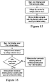
- a voltage detection circuit may be provided which is in electrical connection with the removable battery and/or an alternative power source.
- a microcontroller may command a switching device to switch power sourcing from the removable battery to the alternative power source.
- the microcontroller may determine if a valid charge state exists. If so, the microcontroller may command the switching device to switch power sourcing from the alterative power source to the removable battery. If not, the microcontroller may command the switching device to continue sourcing power from the alternative power source.
- the switching device may be electrically interposed between the removable battery and the alternative power source and various system boards for the cart.
- the illustrated cart 10 is shown merely for exemplary purposes and is not intended to be limiting.
- the body 46, base 32, wheels 34, and work platform 44 may be provided in any size and/or shape, in addition to other components, and/or may be excluded.
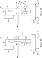
- the power bus 40 may be in electrical connection with a controller 54.
- the controller 54 may be configured to control certain operations of the cart 10 shown and described herein.
- the battery 20 may be removed from the holder 22.
- the time it takes to move the holder 22 from the secured position to the fully unsecured position may provide sufficient time for the cart 10 to begin sourcing power only from the second battery 38 and/or an alternative power source. Removal of the battery 20 from the holder 22 may be detected by the first sensor 11 and indicated to the user, such as by display at the display 42, audible alert, notification, some combination thereof, or the like.
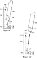
- the power bus 140 may be in electrical connection with a controller 154.
- the controller 154 may be configured to control certain operations of the cart 110 shown and described herein.
- the cavity 119 and protrusion 117 may be configured to mate to guide the battery 120 into the holder 122 and maintain its position within the holder 122 until manually removed by the user.
- the holder 112 may comprise a front lip 156 and/or side walls 158 configured to assist with securing the battery 120 within the holder 122 during such removal and insertion.
- the fully secured position may include placing the battery 120 vertically within the holder 122, though any position may be utilized.
- the partially and fully unsecured positions may comprise rotating the battery 120 away from the body 46 at an increasing angle.
- Operations described herein may be performed, at least in part, by instruction from the controller 154.
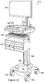
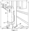
- FIGURE 9 illustrates another exemplary embodiment of the cart 210.
- a plug 250 may be provided for connection to wall outlet or other utility power.
- the plug 250 may be in electrical connection with a power bus 240. Operations described herein may be performed, at least in part, by instruction from the controller 254.
- the controller 254 may be configured to control certain operations of the cart 110 shown and described herein.
- the drawing of power from a particular power source may be realized exclusively or in combination with drawing power from other power sources (e.g., battery 120, back-up battery 138, plug 250).
- a tray 347 may be provided along the body 346.
- the tray 347 may be located above or between the storage devices 345.
- the tray 347 in exemplary embodiments, may be configured for selective movement out and away from the body 346.
- the tray 347 may be configured to accommodate a keyboard.
- FIGURE 17A through FIGURE 17B illustrates an exemplary circuit diagram for the cart 310.
- Various cart 310 systems may be connected to the battery board 360 including, but not limited to, various system boards 368 for various functions of the cart 310 including but not limited to task lights, base lights, lifts for the work platform 344, displays 342, or other cart 310 components.
- the various system boards 368 may alternatively or additionally control, for example without limitation, the storage devices 345 and locking mechanisms for the same, the control system 343, the display 342, the wheels 334, combinations thereof, or the like.
- any embodiment of the present invention may include any of the features of the other embodiments of the present invention.
- the exemplary embodiments herein disclosed are not intended to be exhaustive or to unnecessarily limit the scope of the invention.
- the exemplary embodiments were chosen and described in order to explain the principles of the present invention so that others skilled in the art may practice the invention. Having shown and described exemplary embodiments of the present invention, those skilled in the art will realize that many variations and modifications may be made to the described invention. Many of those variations and modifications will provide the same result and fall within the spirit of the claimed invention. It is the intention, therefore, to limit the invention only as indicated by the scope of the claims.
Landscapes
- Health & Medical Sciences (AREA)
- Engineering & Computer Science (AREA)
- Life Sciences & Earth Sciences (AREA)
- Power Engineering (AREA)
- Surgery (AREA)
- Medical Informatics (AREA)
- Biomedical Technology (AREA)
- Heart & Thoracic Surgery (AREA)
- Nuclear Medicine, Radiotherapy & Molecular Imaging (AREA)
- Molecular Biology (AREA)
- Animal Behavior & Ethology (AREA)
- General Health & Medical Sciences (AREA)
- Public Health (AREA)
- Veterinary Medicine (AREA)
- Accommodation For Nursing Or Treatment Tables (AREA)
- Charge And Discharge Circuits For Batteries Or The Like (AREA)
Applications Claiming Priority (1)
| Application Number | Priority Date | Filing Date | Title |
|---|---|---|---|
| US17/113,905 US20220071827A1 (en) | 2019-07-03 | 2020-12-07 | Medical cart providing data continuity |
Publications (3)
| Publication Number | Publication Date |
|---|---|
| EP4008288A1 true EP4008288A1 (fr) | 2022-06-08 |
| EP4008288C0 EP4008288C0 (fr) | 2023-11-22 |
| EP4008288B1 EP4008288B1 (fr) | 2023-11-22 |
Family
ID=78825049
Family Applications (1)
| Application Number | Title | Priority Date | Filing Date |
|---|---|---|---|
| EP21212982.9A Active EP4008288B1 (fr) | 2020-12-07 | 2021-12-07 | Chariot médical fournissant une continuité de données |
Country Status (2)
| Country | Link |
|---|---|
| EP (1) | EP4008288B1 (fr) |
| AU (1) | AU2021277772B2 (fr) |
Cited By (2)
| Publication number | Priority date | Publication date | Assignee | Title |
|---|---|---|---|---|
| CN115708722A (zh) * | 2022-11-11 | 2023-02-24 | 深圳市理邦精密仪器股份有限公司 | 医疗台车 |
| CN117059997A (zh) * | 2023-08-31 | 2023-11-14 | 深圳开立生物医疗科技股份有限公司 | 电池包组件、台车以及便携式超声系统 |
Citations (4)
| Publication number | Priority date | Publication date | Assignee | Title |
|---|---|---|---|---|
| US20150223891A1 (en) * | 2014-02-07 | 2015-08-13 | Enovate Medical Llc | Medical cart access control |
| US20170141597A1 (en) * | 2015-11-16 | 2017-05-18 | Bytec Healthcare Limited | Programmable Power Module for Mobile Cart |
| US9680333B1 (en) * | 2013-03-15 | 2017-06-13 | Capsa Solutions, Llc | Power system for a medical cart with a direct current power bus |
| US20200206400A1 (en) * | 2018-12-26 | 2020-07-02 | Sun Medical Technology Research Corporation | Blood pump controller and ventricular assist system |
Family Cites Families (4)
| Publication number | Priority date | Publication date | Assignee | Title |
|---|---|---|---|---|
| KR0138350B1 (ko) * | 1993-04-28 | 1998-06-15 | 김광호 | 지능화된 밧데리 전원 시스템 |
| US8227943B2 (en) * | 2008-02-25 | 2012-07-24 | Lee Melvin Harbin | Power system retrofit kit for mobile workstation and retrofit method |
| US8893837B2 (en) * | 2011-06-14 | 2014-11-25 | Samsung Sdi Co., Ltd. | Battery pack storing device and electric vehicle including the same |
| US9914501B2 (en) * | 2014-03-18 | 2018-03-13 | Askoll Eva S.R.L. | Battery holder device for electric bicycle |
-
2021
- 2021-12-03 AU AU2021277772A patent/AU2021277772B2/en active Active
- 2021-12-07 EP EP21212982.9A patent/EP4008288B1/fr active Active
Patent Citations (4)
| Publication number | Priority date | Publication date | Assignee | Title |
|---|---|---|---|---|
| US9680333B1 (en) * | 2013-03-15 | 2017-06-13 | Capsa Solutions, Llc | Power system for a medical cart with a direct current power bus |
| US20150223891A1 (en) * | 2014-02-07 | 2015-08-13 | Enovate Medical Llc | Medical cart access control |
| US20170141597A1 (en) * | 2015-11-16 | 2017-05-18 | Bytec Healthcare Limited | Programmable Power Module for Mobile Cart |
| US20200206400A1 (en) * | 2018-12-26 | 2020-07-02 | Sun Medical Technology Research Corporation | Blood pump controller and ventricular assist system |
Cited By (2)
| Publication number | Priority date | Publication date | Assignee | Title |
|---|---|---|---|---|
| CN115708722A (zh) * | 2022-11-11 | 2023-02-24 | 深圳市理邦精密仪器股份有限公司 | 医疗台车 |
| CN117059997A (zh) * | 2023-08-31 | 2023-11-14 | 深圳开立生物医疗科技股份有限公司 | 电池包组件、台车以及便携式超声系统 |
Also Published As
| Publication number | Publication date |
|---|---|
| AU2021277772B2 (en) | 2024-10-10 |
| AU2021277772A1 (en) | 2022-06-23 |
| EP4008288C0 (fr) | 2023-11-22 |
| EP4008288B1 (fr) | 2023-11-22 |
Similar Documents
| Publication | Publication Date | Title |
|---|---|---|
| US20220071827A1 (en) | Medical cart providing data continuity | |
| EP4008288B1 (fr) | Chariot médical fournissant une continuité de données | |
| US11223227B1 (en) | Medical cart providing data continuity | |
| JP6332811B2 (ja) | 移動カート用の電源システム及び電源システムの動作方法 | |
| US9680333B1 (en) | Power system for a medical cart with a direct current power bus | |
| US20250183702A1 (en) | Power system for mobile workstation | |
| CN102040010B (zh) | 电动商用车电池更换装置及换电系统 | |
| EP3092187B1 (fr) | Robot de transport d'articles muni de batteries principales interchangeable | |
| JP3465674B2 (ja) | 無停電性二重化電源装置におけるユニットの抜き差し構造 | |
| CN101960441A (zh) | 具有移动工作站群的医疗机构中的收集或处理数据的系统 | |
| US12029695B2 (en) | Energy storage device management for a patient support apparatus | |
| EP2700116B1 (fr) | Alimentation électrique multisource | |
| US6612664B2 (en) | Modular cabinets with portable stand mount | |
| CN116746174A (zh) | 远程控制设备的省电 | |
| US12288891B2 (en) | Mobile swappable battery for a powered workstation | |
| EP4348396B1 (fr) | Alimentation électrique sans coupure à station d'accueil intégrée | |
| EP4047772B1 (fr) | Module de batterie avec une charge basse tension automatisée | |
| JP2008148462A (ja) | 電源装置を備える移動体 | |
| WO2025099230A1 (fr) | Alimentation de dispositifs électroniques | |
| JP2005250943A (ja) | インタフェース手段を介して電源供給可能な外部接続機器および処理装置 | |
| US20250362726A1 (en) | Improvements to a Portable Power Supply Apparatus | |
| CN215066912U (zh) | 一种电力监测装置 | |
| GB2612895A (en) | An energy storage system for a load handling device | |
| JPH04114733U (ja) | 無停電電源装置 | |
| CN107817885A (zh) | 能够提升电能供应稳定性的储能装置及电源管理方法 |
Legal Events
| Date | Code | Title | Description |
|---|---|---|---|
| PUAI | Public reference made under article 153(3) epc to a published international application that has entered the european phase |
Free format text: ORIGINAL CODE: 0009012 |
|
| STAA | Information on the status of an ep patent application or granted ep patent |
Free format text: STATUS: THE APPLICATION HAS BEEN PUBLISHED |
|
| AK | Designated contracting states |
Kind code of ref document: A1 Designated state(s): AL AT BE BG CH CY CZ DE DK EE ES FI FR GB GR HR HU IE IS IT LI LT LU LV MC MK MT NL NO PL PT RO RS SE SI SK SM TR |
|
| STAA | Information on the status of an ep patent application or granted ep patent |
Free format text: STATUS: REQUEST FOR EXAMINATION WAS MADE |
|
| 17P | Request for examination filed |
Effective date: 20221207 |
|
| RBV | Designated contracting states (corrected) |
Designated state(s): AL AT BE BG CH CY CZ DE DK EE ES FI FR GB GR HR HU IE IS IT LI LT LU LV MC MK MT NL NO PL PT RO RS SE SI SK SM TR |
|
| GRAP | Despatch of communication of intention to grant a patent |
Free format text: ORIGINAL CODE: EPIDOSNIGR1 |
|
| STAA | Information on the status of an ep patent application or granted ep patent |
Free format text: STATUS: GRANT OF PATENT IS INTENDED |
|
| RIC1 | Information provided on ipc code assigned before grant |
Ipc: A61B 50/18 20160101ALN20230511BHEP Ipc: H02J 9/00 20060101ALI20230511BHEP Ipc: H02J 7/00 20060101ALI20230511BHEP Ipc: A61B 50/13 20160101AFI20230511BHEP |
|
| INTG | Intention to grant announced |
Effective date: 20230609 |
|
| RIN1 | Information on inventor provided before grant (corrected) |
Inventor name: JONES, AUBREY Inventor name: ST. PIERRE, JOHN Inventor name: PHILLIPS, JUSTIN |
|
| GRAS | Grant fee paid |
Free format text: ORIGINAL CODE: EPIDOSNIGR3 |
|
| GRAA | (expected) grant |
Free format text: ORIGINAL CODE: 0009210 |
|
| STAA | Information on the status of an ep patent application or granted ep patent |
Free format text: STATUS: THE PATENT HAS BEEN GRANTED |
|
| AK | Designated contracting states |
Kind code of ref document: B1 Designated state(s): AL AT BE BG CH CY CZ DE DK EE ES FI FR GB GR HR HU IE IS IT LI LT LU LV MC MK MT NL NO PL PT RO RS SE SI SK SM TR |
|
| REG | Reference to a national code |
Ref country code: GB Ref legal event code: FG4D |
|
| REG | Reference to a national code |
Ref country code: CH Ref legal event code: EP Ref country code: DE Ref legal event code: R096 Ref document number: 602021007037 Country of ref document: DE |
|
| REG | Reference to a national code |
Ref country code: IE Ref legal event code: FG4D |
|
| U01 | Request for unitary effect filed |
Effective date: 20231222 |
|
| U07 | Unitary effect registered |
Designated state(s): AT BE BG DE DK EE FI FR IT LT LU LV MT NL PT SE SI Effective date: 20240124 |
|
| U20 | Renewal fee for the european patent with unitary effect paid |
Year of fee payment: 3 Effective date: 20240227 |
|
| PG25 | Lapsed in a contracting state [announced via postgrant information from national office to epo] |
Ref country code: GR Free format text: LAPSE BECAUSE OF FAILURE TO SUBMIT A TRANSLATION OF THE DESCRIPTION OR TO PAY THE FEE WITHIN THE PRESCRIBED TIME-LIMIT Effective date: 20240223 |
|
| PG25 | Lapsed in a contracting state [announced via postgrant information from national office to epo] |
Ref country code: IS Free format text: LAPSE BECAUSE OF FAILURE TO SUBMIT A TRANSLATION OF THE DESCRIPTION OR TO PAY THE FEE WITHIN THE PRESCRIBED TIME-LIMIT Effective date: 20240322 |
|
| PG25 | Lapsed in a contracting state [announced via postgrant information from national office to epo] |
Ref country code: ES Free format text: LAPSE BECAUSE OF FAILURE TO SUBMIT A TRANSLATION OF THE DESCRIPTION OR TO PAY THE FEE WITHIN THE PRESCRIBED TIME-LIMIT Effective date: 20231122 |
|
| PG25 | Lapsed in a contracting state [announced via postgrant information from national office to epo] |
Ref country code: IS Free format text: LAPSE BECAUSE OF FAILURE TO SUBMIT A TRANSLATION OF THE DESCRIPTION OR TO PAY THE FEE WITHIN THE PRESCRIBED TIME-LIMIT Effective date: 20240322 Ref country code: GR Free format text: LAPSE BECAUSE OF FAILURE TO SUBMIT A TRANSLATION OF THE DESCRIPTION OR TO PAY THE FEE WITHIN THE PRESCRIBED TIME-LIMIT Effective date: 20240223 Ref country code: ES Free format text: LAPSE BECAUSE OF FAILURE TO SUBMIT A TRANSLATION OF THE DESCRIPTION OR TO PAY THE FEE WITHIN THE PRESCRIBED TIME-LIMIT Effective date: 20231122 |
|
| PG25 | Lapsed in a contracting state [announced via postgrant information from national office to epo] |
Ref country code: RS Free format text: LAPSE BECAUSE OF FAILURE TO SUBMIT A TRANSLATION OF THE DESCRIPTION OR TO PAY THE FEE WITHIN THE PRESCRIBED TIME-LIMIT Effective date: 20231122 Ref country code: PL Free format text: LAPSE BECAUSE OF FAILURE TO SUBMIT A TRANSLATION OF THE DESCRIPTION OR TO PAY THE FEE WITHIN THE PRESCRIBED TIME-LIMIT Effective date: 20231122 Ref country code: NO Free format text: LAPSE BECAUSE OF FAILURE TO SUBMIT A TRANSLATION OF THE DESCRIPTION OR TO PAY THE FEE WITHIN THE PRESCRIBED TIME-LIMIT Effective date: 20240222 Ref country code: HR Free format text: LAPSE BECAUSE OF FAILURE TO SUBMIT A TRANSLATION OF THE DESCRIPTION OR TO PAY THE FEE WITHIN THE PRESCRIBED TIME-LIMIT Effective date: 20231122 |
|
| PG25 | Lapsed in a contracting state [announced via postgrant information from national office to epo] |
Ref country code: CZ Free format text: LAPSE BECAUSE OF FAILURE TO SUBMIT A TRANSLATION OF THE DESCRIPTION OR TO PAY THE FEE WITHIN THE PRESCRIBED TIME-LIMIT Effective date: 20231122 |
|
| PG25 | Lapsed in a contracting state [announced via postgrant information from national office to epo] |
Ref country code: SK Free format text: LAPSE BECAUSE OF FAILURE TO SUBMIT A TRANSLATION OF THE DESCRIPTION OR TO PAY THE FEE WITHIN THE PRESCRIBED TIME-LIMIT Effective date: 20231122 |
|
| PG25 | Lapsed in a contracting state [announced via postgrant information from national office to epo] |
Ref country code: SM Free format text: LAPSE BECAUSE OF FAILURE TO SUBMIT A TRANSLATION OF THE DESCRIPTION OR TO PAY THE FEE WITHIN THE PRESCRIBED TIME-LIMIT Effective date: 20231122 Ref country code: SK Free format text: LAPSE BECAUSE OF FAILURE TO SUBMIT A TRANSLATION OF THE DESCRIPTION OR TO PAY THE FEE WITHIN THE PRESCRIBED TIME-LIMIT Effective date: 20231122 Ref country code: RO Free format text: LAPSE BECAUSE OF FAILURE TO SUBMIT A TRANSLATION OF THE DESCRIPTION OR TO PAY THE FEE WITHIN THE PRESCRIBED TIME-LIMIT Effective date: 20231122 Ref country code: CZ Free format text: LAPSE BECAUSE OF FAILURE TO SUBMIT A TRANSLATION OF THE DESCRIPTION OR TO PAY THE FEE WITHIN THE PRESCRIBED TIME-LIMIT Effective date: 20231122 |
|
| REG | Reference to a national code |
Ref country code: DE Ref legal event code: R097 Ref document number: 602021007037 Country of ref document: DE |
|
| PG25 | Lapsed in a contracting state [announced via postgrant information from national office to epo] |
Ref country code: MC Free format text: LAPSE BECAUSE OF FAILURE TO SUBMIT A TRANSLATION OF THE DESCRIPTION OR TO PAY THE FEE WITHIN THE PRESCRIBED TIME-LIMIT Effective date: 20231122 |
|
| PG25 | Lapsed in a contracting state [announced via postgrant information from national office to epo] |
Ref country code: MC Free format text: LAPSE BECAUSE OF FAILURE TO SUBMIT A TRANSLATION OF THE DESCRIPTION OR TO PAY THE FEE WITHIN THE PRESCRIBED TIME-LIMIT Effective date: 20231122 |
|
| PLBE | No opposition filed within time limit |
Free format text: ORIGINAL CODE: 0009261 |
|
| STAA | Information on the status of an ep patent application or granted ep patent |
Free format text: STATUS: NO OPPOSITION FILED WITHIN TIME LIMIT |
|
| REG | Reference to a national code |
Ref country code: IE Ref legal event code: MM4A |
|
| PG25 | Lapsed in a contracting state [announced via postgrant information from national office to epo] |
Ref country code: IE Free format text: LAPSE BECAUSE OF NON-PAYMENT OF DUE FEES Effective date: 20231207 |
|
| 26N | No opposition filed |
Effective date: 20240823 |
|
| PG25 | Lapsed in a contracting state [announced via postgrant information from national office to epo] |
Ref country code: IE Free format text: LAPSE BECAUSE OF NON-PAYMENT OF DUE FEES Effective date: 20231207 |
|
| U20 | Renewal fee for the european patent with unitary effect paid |
Year of fee payment: 4 Effective date: 20241126 |
|
| PG25 | Lapsed in a contracting state [announced via postgrant information from national office to epo] |
Ref country code: CY Free format text: LAPSE BECAUSE OF FAILURE TO SUBMIT A TRANSLATION OF THE DESCRIPTION OR TO PAY THE FEE WITHIN THE PRESCRIBED TIME-LIMIT; INVALID AB INITIO Effective date: 20211207 |
|
| REG | Reference to a national code |
Ref country code: CH Ref legal event code: PL |
|
| PG25 | Lapsed in a contracting state [announced via postgrant information from national office to epo] |
Ref country code: CH Free format text: LAPSE BECAUSE OF NON-PAYMENT OF DUE FEES Effective date: 20241231 |
|
| PG25 | Lapsed in a contracting state [announced via postgrant information from national office to epo] |
Ref country code: TR Free format text: LAPSE BECAUSE OF FAILURE TO SUBMIT A TRANSLATION OF THE DESCRIPTION OR TO PAY THE FEE WITHIN THE PRESCRIBED TIME-LIMIT Effective date: 20231122 |
|
| U20 | Renewal fee for the european patent with unitary effect paid |
Year of fee payment: 5 Effective date: 20251120 |