EP4008290B1 - Procédé de programmation d'un composant d'orthopédie maxillaire à partir d'une matière à mémoire de forme - Google Patents
Procédé de programmation d'un composant d'orthopédie maxillaire à partir d'une matière à mémoire de forme Download PDFInfo
- Publication number
- EP4008290B1 EP4008290B1 EP21206150.1A EP21206150A EP4008290B1 EP 4008290 B1 EP4008290 B1 EP 4008290B1 EP 21206150 A EP21206150 A EP 21206150A EP 4008290 B1 EP4008290 B1 EP 4008290B1
- Authority
- EP
- European Patent Office
- Prior art keywords
- orthodontic
- target
- baking mold
- mold
- shape
- Prior art date
- Legal status (The legal status is an assumption and is not a legal conclusion. Google has not performed a legal analysis and makes no representation as to the accuracy of the status listed.)
- Active
Links
Images


Classifications
-
- A—HUMAN NECESSITIES
- A61—MEDICAL OR VETERINARY SCIENCE; HYGIENE
- A61C—DENTISTRY; APPARATUS OR METHODS FOR ORAL OR DENTAL HYGIENE
- A61C7/00—Orthodontics, i.e. obtaining or maintaining the desired position of teeth, e.g. by straightening, evening, regulating, separating, or by correcting malocclusions
- A61C7/12—Brackets; Arch wires; Combinations thereof; Accessories therefor
- A61C7/20—Arch wires
-
- A—HUMAN NECESSITIES
- A61—MEDICAL OR VETERINARY SCIENCE; HYGIENE
- A61C—DENTISTRY; APPARATUS OR METHODS FOR ORAL OR DENTAL HYGIENE
- A61C7/00—Orthodontics, i.e. obtaining or maintaining the desired position of teeth, e.g. by straightening, evening, regulating, separating, or by correcting malocclusions
- A61C7/12—Brackets; Arch wires; Combinations thereof; Accessories therefor
- A61C7/28—Securing arch wire to bracket
-
- C—CHEMISTRY; METALLURGY
- C22—METALLURGY; FERROUS OR NON-FERROUS ALLOYS; TREATMENT OF ALLOYS OR NON-FERROUS METALS
- C22F—CHANGING THE PHYSICAL STRUCTURE OF NON-FERROUS METALS AND NON-FERROUS ALLOYS
- C22F1/00—Changing the physical structure of non-ferrous metals or alloys by heat treatment or by hot or cold working
- C22F1/006—Resulting in heat recoverable alloys with a memory effect
-
- A—HUMAN NECESSITIES
- A61—MEDICAL OR VETERINARY SCIENCE; HYGIENE
- A61C—DENTISTRY; APPARATUS OR METHODS FOR ORAL OR DENTAL HYGIENE
- A61C2201/00—Material properties
- A61C2201/007—Material properties using shape memory effect
Definitions
- the invention relates to a method for programming an orthodontic component made of a shape memory material.
- Orthodontic treatment of patients with a removable appliance is advantageous for minor deformities, while more difficult treatments often require the use of fixed appliances.
- Removable appliances usually consist of an individually laboratory-made plastic base with clamps and correction elements made of stainless steel wire, some of which are also provided with orthodontic screws. With these braces u. a. correct the position of crooked teeth, the width of the dental arches and the position of incorrectly positioned jaws.
- Orthodontic components of removable appliances can also be a spring, a wire section as a labial arch or a protrusion spring, a holding element or a U-bolt.
- These elements can be made of steel, especially stainless steel. Alternatively, however, these elements can also consist of a shape-memory material.
- orthodontic wires made of a shape memory material are often inserted into the brackets at the beginning of the treatment in order to achieve "rough" alignment of the teeth.
- Steel wires, for example, are only used towards the end of the orthodontic treatment in order to move the teeth as precisely as possible into a defined position.
- orthodontic components for example U-bars or labial arches for a removable appliance, made of steel can be converted into a desired target geometry with the aid of pliers in order to exert a desired force on one or more teeth.
- bending robots are used to bend them into a desired target shape.
- the bending robot receives the necessary data for bending the orthodontic wire from an orthodontist's planning software, in which a patient's teeth are virtually available with the associated brackets and the course of the orthodontic arch is automatically calculated for a specific treatment step and then exported to the bending robot.
- the most important shape memory materials include Cu-Zn-X (X: Si, Sn, Al) alloys and the intermetallic NiTi alloy (nickel content of approx. 55% by weight), with the NiTi alloy being of greater technological importance due to its more favorable properties could attain.
- the shape memory effect is based on a thermoelastic martensite transformation, a reversible phase transformation caused by shearing of the lattice planes.
- the cooling of the high-temperature phase, called austenite, below the alloy-specific martensite start temperature leads to the phase transformation without shape change and without irreversible plastic deformation, as is the case with steels.
- Shape memory alloys are easily deformed in the martensitic state; the reversible deformation can be up to 8% for NiTi. This deformation is permanent as long as the alloy is in the martensitic state. Heating above the alloy-specific austenite start temperature then leads to the restoration of the original shape.
- an orthodontic component made of a shape-memory material into a target geometry it is brought into the desired target geometry in a special baking mold and then heated to a transition temperature specific to the shape-memory material.
- the orthodontic component is then cooled again and placed in a orthodontic appliance inserted into a patient under deformation.
- the orthodontic component is reheated and remembers its target geometry, into which it then wants to deform back.
- the orthodontic component exerts a force on brackets or teeth in order to move them in a certain direction.
- the parameters to be used for programming an orthodontic component such as transition temperature, duration of the programming process, etc., depend on the shape memory material and are specified by the manufacturer of the shape memory material or the manufacturer of the orthodontic component and the user, e.g. the orthodontist or the dental laboratory, on request.
- an orthodontic component made of a shape memory material is bent from an initial shape to a target shape (and possibly programmed in this way) and there is a strong bending of the orthodontic component during the transition from the initial shape to the target shape (beyond a maximum bending angle), this occurs it means that the shape memory material is plastically deformed in the area of the strong bend and/or becomes brittle in this section. Both lead to the material behavior in the section changing in an unfavorable manner and the orthodontic component no longer exerting the desired force in the orthodontic appliance.
- the maximum bending angle depends on various parameters of the orthodontic component: on the one hand its geometric shape and on the other hand on the shape memory material from which the orthodontic component is made. However, the maximum bending angles also depend on the bending direction about which the orthodontic component, for example the orthodontic wire, is to be bent. If the orthodontic component has, for example, a rectangular cross section, it makes a difference whether the orthodontic component is to be bent around the narrow or thin or the wide or thick side of the rectangle.
- the term strong bending is to be understood as meaning a bending of the orthodontic component that goes beyond elastic deformation.
- the orthodontic component is made of one Shape memory material is bent to such an extent that plastic deformation occurs in the area of severe bending and/or the material becomes brittle in the area of severe bending.
- the US 2014/0234794 A1 discloses a method of deforming an orthodontic wire made of a shape memory material into a target geometry for proper insertion into a patient-specific appliance, particularly fixed brackets placed on a patient's teeth.
- a patient-specific target set-up of the patient's upper or lower jaw is created.
- Brackets are then placed on the teeth to be treated in the target set-up.
- a two-dimensional image is created from the top view of the respective target set-up, for example a photo is created in the top view of the target set-up. This two-dimensional image is loaded into a data processing system and the position of the slot is identified for each bracket.
- the data obtained in this way on the position of the slots is exported from the data processing system in order to create a baking mold for an orthodontic wire made from a shape-memory material, for example milled from an aluminum plate.
- wire fixing sections are generated in the baking mold that hold the wire in the areas corresponding to the slots during baking.
- the orthodontic wire to be programmed is then inserted into the baking mold and baked in order to program it in the target geometry.
- the orthodontic wire is thus programmed from its starting geometry into the target geometry in a single process step, ie programmed immediately and directly into its target geometry. Accordingly, the physical limits that apply to the respective wire, depending on the diameter of the wire and the degree of deformation/bending, must be observed when programming in the target geometry and form the limits for programming the wire.
- a method for programming an orthodontic nitinol wire in which bores are provided in a base plate, which are arranged along a (jaw) arch shape; pins with an internal thread can be placed in the bores, with a screw being able to be screwed into the internal thread in order to clamp an orthodontic wire between the screw and the pin; a nitinol wire to be programmed is placed in a desired position along the arch form on each of the pins and between the respective screw and clamped to the respective pin, as a result of which the wire assumes the desired target geometry on the base plate; When the wire is in its desired target geometry, the base plate is placed with the wire in an oven and baked there to program the wire in its target geometry. With this method, too, the orthodontic wire is deformed or programmed from a generally linear starting geometry directly and in one step into the desired target geometry.
- a real orthodontic wire is then bent into the desired target geometry, e.g. by a bending robot or by hand, and held in the target geometry.
- a heat treatment is carried out in the target geometry, e.g. by means of electricity or heat in an oven, in order to program the wire into the target geometry.
- the EP 3370638 B1 is based on the treatment of an orthodontic malposition using an aligner: several intermediate positions are calculated between an ACTUAL position of the teeth in a jaw and an associated TARGET position of the teeth in the respective jaw. A treatment splint is then created for each intermediate position and the patient wears the treatment splint created for each intermediate position in ascending order in order to move the teeth from the ACTUAL position through the respective intermediate positions to the TARGET position.
- the EP 2270638 B1 to whose patent family the US2020/0315747A1 belongs, the previously several treatment rails are to be replaced by a single treatment rail.
- the purpose of the invention is to program a treatment splint made of a shape memory polymer at different temperatures with the aid of, for example, ionizing radiation on different intermediate models according to the intermediate positions.
- the patient then wears one treatment splint and heats it - at the end of each treatment step according to the respective intermediate positions - to ever higher temperatures, which means that more and more crystalline structures of one treatment splint are destroyed and the treatment splint for the next treatment step that follows, corresponding to the next intermediate position , is programmed.
- the programming of one treatment rail EP 3370638 B1 thus starts programming in the target position and ends with the actual position, ie in reverse order to the treatment.
- This reverse order of programming is possible because there are no programming limitations of the shape memory polymer to consider.
- the one in the EP 3370638 B1 The methods described for programming shape-memory polymers cannot be transferred to shape-memory materials made of metal either: On the one hand, the methods themselves are unsuitable, for example ionizing radiation. On the other hand, in the method described above, crystalline structures of the shape memory polymer of the treatment splint are gradually destroyed, as a result of which the treatment splint itself is gradually destroyed.
- the object of the present invention is to specify a method for deforming an orthodontic component made of a shape memory material, in which an unfavorable change in the material behavior is reduced or avoided even in the case of severe bending.
- an orthodontic wire for use in a slot of a bracket, a spring, a wire section as a labial arch or a protrusion spring of a removable appliance, a holding element of a removable appliance or a U-bracket of a removable appliance can be provided as an orthodontic component.
- an intermediate baking mold is created in step 1e), with which steps 1f) and 1g) are carried out.
- step 1e a first intermediate baking mold is created, with which steps 1f) and 1g) are carried out, and a second intermediate baking mold is created, with which steps 1f) and 1g) are then carried out.
- a first intermediate baking mold is created in step 1e), with which steps 1f) and 1g) are carried out, and a second intermediate baking mold is created with which steps 1f) and 1g) are subsequently carried out, and it is creates a third intermediate baking mold, with which steps 1f) and 1g) are then carried out.
- an intermediate pan preferably half of the severe bend is made through the intermediate pan and the other half of the severe bend is through the target pan.
- three intermediate baking molds are used, a quarter of the strong bend is preferably carried out with the first as well as with the second and with the third intermediate baking mold, and the fourth quarter of the strong bend is carried out with the target baking mold.
- the strong bend As an alternative to distributing the strong bend evenly over the various baking molds, it is possible to distribute the strong bend in bends of different sizes over the respective baking molds. For example, with the first Intermediate baking mold a predominant or substantial part of the strong bending are carried out and only a small or insignificant part of the strong bending is carried out with the target baking mold. Furthermore, for example, only a small or insignificant part of the strong bending can be carried out with the first intermediate baking mold and a predominant or substantial part of the strong bending can be carried out with the target baking mold.
- first intermediate pan preferably between 50 and 90% of the severe bend is performed with the intermediate pan and 50 to 10% of the severe bend is performed with the target mold.
- two intermediate baking molds preferably 20-70% of the strong bending is carried out with the first intermediate baking mold and 20-50% with the second intermediate baking mold and 10-40% with the target baking mold.
- three intermediate molds it is preferable to use the first intermediate mold for 20-70% and the second intermediate mold for 10-40% and the third intermediate mold for 10-40% and the target mold for 10-40% of the severe bending.
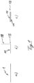
- Fig. 1a schematically shows an orthodontic wire 1, as is present in an orthodontic practice or a dental laboratory.
- the orthodontic wire is shown in its original form: it is linear or straight and has a length and cross-section typical of an orthodontic wire.
- the orthodontic wire 1 is formed of a shape memory material.
- the orthodontic wire is intended for use as an orthodontic component in a removable appliance, e.g. as a labial arch, protrusion spring, retaining element or U-bolt.
- the orthodontic wire 1 is previously programmed to a specific target shape.
- the necessary process parameters for baking the orthodontic wire 1 are typically made available by the manufacturer and/or supplier of the orthodontic wire 1 upon request.
- To program orthodontic wire 1 into a target shape the following steps are performed: creating a target mold for the orthodontic wire, inserting the orthodontic wire into the target mold, and baking the orthodontic wire in the target mold to program it in the target shape,
- Fig. 1b shows a schematic representation of the orthodontic wire 1 of FIG Fig. 1a ), wherein the orthodontic wire 1 has a bend 1B between a first portion 11 and a second portion 12 of the orthodontic wire 1.
- the bend 1B is designed as a 90° bend.
- FIG. 1c shows a schematic representation of the orthodontic wire 1 of FIG Fig. 1a ), wherein the orthodontic wire 1 has a bend 1B between a first portion 11 and a second portion 12 of the orthodontic wire 1.
- the bend 1B is designed as a 180° bend.
- Fig. 1b ) and c) show orthodontic wire bends 1B of 90° and 180°, respectively, which are severe bends for most orthodontic wires.
- the orthodontic wires 1 of 1b) and 1c ) are of course not suitable in the form shown for use in a patient's orthodontic appliance.
- this simplified representation of an orthodontic wire 1 with only one bend 1B is sufficient for explaining the principles of the present invention, as of course several bends 1B and bends 1B of different degrees can be made in the orthodontic wire 1 in order to convert it into a target shape , as required for a patient's fixed bracket.
- Figure 2a shows the orthodontic wire 1 in its initial form, in which it is provided by the manufacturer.
- the orthodontic wire 1 is to be converted into a target shape with a 90° bend in order to be used, for example, as a labial arch in a removable appliance, although further bends would of course be necessary for this.
- the orthodontic wire 1 of Figure 2a is used in a next step in an intermediate baking mold, not shown, and baked in this and subsequently cooled.
- the orthodontic wire 1 has a bend 1B of 45° between a first section 11 and a second section 12 .
- the orthodontic wire 1 is the Figure 2b ) placed in a non-illustrated target baking pan and baked in this and subsequently cooled.
- the result of this step is in Figure 2c ) shown: the orthodontic wire 1 has between the first section 11 and the second section 12 a bend 1B of 90°.
- the orthodontic wire 1 is placed in an intermediate mold with a 45° bend according to Figure 2b ) provided and only from this form of Figure 2b ) into the target form of the Figure 2c ) transferred with the help of the target baking pan. In this way, the sharp bend of 90° was avoided.
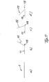
- Figure 3a shows the orthodontic wire 1 in its initial form, in which it is provided by the manufacturer.
- the orthodontic wire 1 is to be converted into a target shape with a 180° bend in order to be used, for example, as a U-bracket in a removable appliance, in which case further bends would of course be necessary.
- the orthodontic wire 1 of Figure 3a is used in a next step in an intermediate baking mold, not shown, and baked in this and subsequently cooled.
- the orthodontic wire 1 has a bend 1B of 60° between a first section 11 and a second section 12 .
- the orthodontic wire 1 is the Figure 3b )
- intermediate baking mold inserted and baked in this and then cooled.
- the result of this step is in 3c ) is shown: the orthodontic wire 1 has a bend 1B of 120° between the first section 11 and the second section 12.
- the orthodontic wire 1 is the 3c ) placed in a non-illustrated target baking pan and baked in this and subsequently cooled.
- the result of this step is in 3d ) shown: the orthodontic wire 1 has a bend 1B of 180° between the first section 11 and the second section 12 .
- the orthodontic wire 1 is bent in the first intermediate mold with a bend of 60° according to Figure 3b ) and in the second intermediate baking pan with a bend of another 60° according to 3c ) provided at 120° and only from this form of 3c ) into the target form of the 3d ) transferred with the help of the target baking pan.
- the total bend of 180° is divided equally into three bends of 60° each.
- Figure 4a shows the orthodontic wire 1 in its original form as provided by the manufacturer.
- the orthodontic wire 1 is to be converted into a target shape with a 135° bend in order to be used, for example, as a holding element in a removable appliance, although further bends would of course be necessary for this.
- the orthodontic wire 1 of Figure 4a is used in a next step in an intermediate baking mold, not shown, and baked in this and subsequently cooled.
- the orthodontic wire 1 has a bend 1B of 60° between a first section 11 and a second section 12 .
- the orthodontic wire 1 is the Figure 4b )
- intermediate baking mold inserted and baked in this and then cooled.
- the orthodontic wire 1 has a bend 1B of 110° between the first section 11 and the second section 12.
- the orthodontic wire 1 is the Figure 4c ) placed in a non-illustrated target baking pan and baked in this and subsequently cooled.
- the orthodontic wire 1 has a bend 1B of 135° between the first section 11 and the second section 12.
- the orthodontic wire 1 is placed in a first intermediate mold with a bend of 60° according to Figure 4b ) and in a second intermediate baking mold with a bend of another 50° according to Figure 4c ) provided at 110° and only from this form of Figure 4c ) into the target form of the Figure 4d ) transferred with the help of the target baking pan.
- the total bend of 135° is divided unequally into three bends of 60° and then 50° and then 25° in the respective baking pans.
Landscapes
- Health & Medical Sciences (AREA)
- Chemical & Material Sciences (AREA)
- Oral & Maxillofacial Surgery (AREA)
- Veterinary Medicine (AREA)
- Public Health (AREA)
- General Health & Medical Sciences (AREA)
- Animal Behavior & Ethology (AREA)
- Life Sciences & Earth Sciences (AREA)
- Epidemiology (AREA)
- Dentistry (AREA)
- Engineering & Computer Science (AREA)
- Organic Chemistry (AREA)
- Metallurgy (AREA)
- Mechanical Engineering (AREA)
- Materials Engineering (AREA)
- Physics & Mathematics (AREA)
- Crystallography & Structural Chemistry (AREA)
- Thermal Sciences (AREA)
- Dental Tools And Instruments Or Auxiliary Dental Instruments (AREA)
Claims (7)
- Procédé de programmation d'un composant orthodontique à partir d'un matériau à mémoire de forme en partant d'une forme initiale du composant orthodontique vers une forme cible à programmer du composant orthodontique, la forme cible présentant au moins par sections une forte flexion par rapport à la forme initiale, une forte flexion étant une flexion du composant orthodontique qui va au-delà d'une déformation élastique, le procédé comprenant les étapes suivantes :a. fournir un composant orthodontique (1) à partir d'un matériau à mémoire de forme dans une forme initiale,b. créer un moule de cuisson cible pour l'élément orthodontique (1),c. mise en place de l'élément orthodontique (1) dans le moule de cuisson cible etd. la cuisson de l'élément orthodontique (1) dans le moule de cuisson cible afin de le programmer dans le moule cible,
caractérisé par les étapes suivantes après l'étape a)e. la réalisation d'au moins un moule de cuisson intermédiaire pour le composant orthodontique (1), dans lequel le composant orthodontique (1) présente une forme intermédiaire entre la forme initiale et la forme cible,f. mise en place de l'élément orthodontique (1) dans le moule de cuisson intermédiaire etg. cuisson de l'élément orthodontique (1) dans le moule de cuisson intermédiaire. - Procédé selon la revendication 1, caractérisé en ce qu'à l'étape 1a), on prépare comme composant orthodontique (1) un fil orthodontique destiné à être inséré dans une fente d'un bracket, un ressort, un tronçon de fil servant d'arc labial ou un ressort de protrusion d'un appareil amovible, un élément de retenue d'un appareil amovible ou un étrier en U d'un appareil amovible.
- Procédé selon la revendication 1 ou 2, caractérisé en ce que, à l'étape 1e), un moule de cuisson intermédiaire est créé, avec lequel les étapes 1f) et 1g) sont exécutées.
- Procédé selon la revendication 1 ou 2, caractérisé en ce que, à l'étape 1e), un premier moule de cuisson intermédiaire est créé, avec lequel les étapes 1f) et 1g) sont exécutées, et un deuxième moule de cuisson intermédiaire est créé, avec lequel les étapes 1f) et 1g) sont ensuite exécutées.
- Procédé selon la revendication 1 ou 2, caractérisé en ce que, à l'étape 1e), un premier moule de cuisson intermédiaire est créé, avec lequel les étapes 1f) et 1g) sont exécutées, et un deuxième moule de cuisson intermédiaire est créé, avec lequel les étapes 1f) et 1g) sont ensuite exécutées, et un troisième moule de cuisson intermédiaire est créé, avec lequel les étapes 1f) et 1g) sont ensuite exécutées.
- Procédé selon l'une quelconque des revendications 3, 4 ou 5, caractérisé en ce que, lorsqu'un moule de cuisson intermédiaire est utilisé, la moitié de la forte flexion est réalisée par le moule de cuisson intermédiaire, et en ce que, lorsque deux moules de cuisson intermédiaires sont utilisés, un tiers de la forte flexion est réalisé à la fois par le premier et le deuxième moule de cuisson intermédiaire, et en ce que, lorsque trois moules de cuisson intermédiaires sont utilisés, un quart de la forte flexion est réalisé à la fois par le premier et le deuxième et par le troisième moule de cuisson intermédiaire.
- Procédé selon l'une des revendications 3, 4 ou 5, caractérisé en ce que, lorsqu'on utilise un moule de cuisson intermédiaire, on réalise avec le moule de cuisson intermédiaire entre 50 et 90% de la forte flexion et avec le moule de cuisson cible entre 50 et 10% de la forte flexion, et en ce que, lorsqu'on utilise deux moules de cuisson intermédiaires, 20-70% de la forte flexion sont réalisés avec la première forme de cuisson intermédiaire et 20-50% avec la deuxième forme de cuisson intermédiaire et 10-40% avec la forme de cuisson cible, et que, si trois formes de cuisson intermédiaires sont utilisées, 20-70% de la forte flexion sont réalisés avec la première forme de cuisson intermédiaire et 10-40% avec la deuxième forme de cuisson intermédiaire et 10-40% avec la troisième forme de cuisson intermédiaire et 10-40% avec la forme de cuisson cible.
Applications Claiming Priority (1)
| Application Number | Priority Date | Filing Date | Title |
|---|---|---|---|
| DE102020214587.3A DE102020214587A1 (de) | 2020-11-19 | 2020-11-19 | Verfahren zum Programmieren eines kieferorthopädischen Bauteils aus einem Formgedächtnismaterial |
Publications (2)
| Publication Number | Publication Date |
|---|---|
| EP4008290A1 EP4008290A1 (fr) | 2022-06-08 |
| EP4008290B1 true EP4008290B1 (fr) | 2023-04-19 |
Family
ID=78516589
Family Applications (1)
| Application Number | Title | Priority Date | Filing Date |
|---|---|---|---|
| EP21206150.1A Active EP4008290B1 (fr) | 2020-11-19 | 2021-11-03 | Procédé de programmation d'un composant d'orthopédie maxillaire à partir d'une matière à mémoire de forme |
Country Status (5)
| Country | Link |
|---|---|
| US (1) | US11813137B2 (fr) |
| EP (1) | EP4008290B1 (fr) |
| JP (2) | JP2022081461A (fr) |
| DE (1) | DE102020214587A1 (fr) |
| ES (1) | ES2946049T3 (fr) |
Family Cites Families (19)
| Publication number | Priority date | Publication date | Assignee | Title |
|---|---|---|---|---|
| JPH07103457B2 (ja) * | 1989-02-10 | 1995-11-08 | トミー株式会社 | 形状記憶合金製矯正ワイヤーの形態付与方法 |
| US5683245A (en) * | 1995-05-30 | 1997-11-04 | Ormco Corporation | Shape memory orthodontic archwire having variable recovery stresses |
| US5843244A (en) * | 1996-06-13 | 1998-12-01 | Nitinol Devices And Components | Shape memory alloy treatment |
| WO1998002109A2 (fr) * | 1996-07-12 | 1998-01-22 | Flexmedics Corporation | Arc en fil metallique orthodontique et procede de fabrication |
| US6293791B1 (en) * | 2000-03-09 | 2001-09-25 | Albert Einstein Healthcare Network | Z-bend orthodontic instrument and method |
| EP2258303B1 (fr) * | 2000-04-19 | 2013-09-18 | OraMetrix, Inc. | Système pour créer un modèle individuel virtuel tridimensionnel d'une dent |
| US6928733B2 (en) * | 2002-11-06 | 2005-08-16 | Lingualcare, Inc. | Method and system for customizing an orthodontic archwire |
| US20070154859A1 (en) * | 2006-01-04 | 2007-07-05 | Hilliard Jack K | Method for localized heat treatment of orthodontic wires |
| US20080254403A1 (en) * | 2007-04-10 | 2008-10-16 | Jack Keith Hilliard | System for cnc-machining fixtures to set orthodontic archwires |
| US8382917B2 (en) * | 2007-12-03 | 2013-02-26 | Ormco Corporation | Hyperelastic shape setting devices and fabrication methods |
| WO2009130744A1 (fr) | 2008-04-25 | 2009-10-29 | パイオニア株式会社 | Dispositif à panneau tactile de type à film résistif, programme et procédé de détection d’un contact dans le dispositif à panneau tactile de type à film résistif |
| US8685184B2 (en) * | 2010-08-24 | 2014-04-01 | Ormco Corporation | Shape setting a shape memory alloy dental arch |
| JP2014521439A (ja) * | 2011-07-29 | 2014-08-28 | スリーエム イノベイティブ プロパティズ カンパニー | 干渉を低減する歯科矯正アーチワイヤ及び関連方法 |
| DE102011081151A1 (de) | 2011-08-17 | 2013-02-21 | Dw Lingual Systems Gmbh | Verfahren zum Verformen eines kieferorthopädischen Drahtes aus einem Formgedächtnismaterial und zugehöriger Draht |
| JP2017527694A (ja) * | 2014-07-14 | 2017-09-21 | スマーター アロイズ インコーポレーテッド | 複記憶材料、システム、方法及びその応用 |
| KR101643504B1 (ko) * | 2015-07-17 | 2016-07-27 | 이종호 | 맞춤형 치아교정 호선 제작키트 및 이를 이용한 치아교정 호선 제작방법 |
| CN108348306B (zh) * | 2015-11-02 | 2021-01-15 | 3M创新有限公司 | 具有连续形状记忆的正畸器具 |
| US10217237B1 (en) * | 2018-06-21 | 2019-02-26 | 3D Med Ag | Systems and methods for forming a desired bend angle in an orthodontic appliance |
| US12144700B2 (en) * | 2020-11-05 | 2024-11-19 | Brius Technologies, Inc. | Dental appliances and associated systems and methods |
-
2020
- 2020-11-19 DE DE102020214587.3A patent/DE102020214587A1/de not_active Withdrawn
-
2021
- 2021-11-03 ES ES21206150T patent/ES2946049T3/es active Active
- 2021-11-03 EP EP21206150.1A patent/EP4008290B1/fr active Active
- 2021-11-18 US US17/529,573 patent/US11813137B2/en active Active
- 2021-11-18 JP JP2021188033A patent/JP2022081461A/ja active Pending
-
2025
- 2025-01-06 JP JP2025001772A patent/JP2025065119A/ja active Pending
Also Published As
| Publication number | Publication date |
|---|---|
| US20220151738A1 (en) | 2022-05-19 |
| JP2025065119A (ja) | 2025-04-17 |
| US11813137B2 (en) | 2023-11-14 |
| ES2946049T3 (es) | 2023-07-12 |
| DE102020214587A1 (de) | 2022-05-19 |
| EP4008290A1 (fr) | 2022-06-08 |
| JP2022081461A (ja) | 2022-05-31 |
Similar Documents
| Publication | Publication Date | Title |
|---|---|---|
| EP3454774B1 (fr) | Dispositif de correction de la mauvaise position des dents et procédé de fabrication d'un élément d'arc pour un tel dispositif | |
| EP2744440B1 (fr) | Procédé de déformation d'un fil métallique d'orthodontie constitué d'un matériau à mémoire de forme | |
| DE69111329T2 (de) | Vorrichtung zum Korrigieren von Skoliose. | |
| WO2002019939A1 (fr) | Appareil a arc palatal compose pour correction de l'alignement des dents | |
| DE102008002389A1 (de) | Vorrichtung zur Osteosynthese sowie zur Fixierung und Stabilisierung von Röhrenknochen | |
| DE112005001944T5 (de) | Dentalzange zum Bilden und Entfernen von Erhebungen an Vorrichtungen | |
| EP3975918B1 (fr) | Ensemble de dispositifs de correction permettant la mise en oeuvre d'une intervention orthodontique | |
| EP2672918B1 (fr) | Procédé de fabrication d'un corps de bague orthodontique spécifique au patient et corps de bague ainsi obtenu | |
| EP0749290A1 (fr) | Extenseur destine a etre place dans un vaisseau du corps | |
| WO2017207665A2 (fr) | Bracket pour dispositif d'orthodontie | |
| WO2016071508A1 (fr) | Procédé de fabrication d'un appareil de repositionnement dentaire précontraint | |
| DE3510925A1 (de) | Orthodontisches system zur zahnbehandlung | |
| DE60309639T2 (de) | Anzugsanker für eine zahnärztliche magnetische Haltevorrichtung | |
| EP2672919B1 (fr) | Procédé de fabrication d'au moins une bague orthodontique spécifique au patient et de structure modulaire | |
| EP4008290B1 (fr) | Procédé de programmation d'un composant d'orthopédie maxillaire à partir d'une matière à mémoire de forme | |
| DE2163292A1 (de) | Orthodontische Vorrichtung | |
| EP2993531B1 (fr) | Procédé de formation d'un ressort | |
| DE112014006389T5 (de) | Rohrverbindungskörper, Behandlungswerkzeug und Verbindungsverfahren | |
| EP3422994B1 (fr) | Attache orthodontique | |
| DE2328231C2 (de) | Vorrichtung zum Richten von Zähnen | |
| EP2950742B1 (fr) | Procédé de production d'appareils médico-dentaires amovibles | |
| EP1049236A2 (fr) | Procédé et dispositif pour plier des barres d'enroulement | |
| AT400099B (de) | Abnehmbarer zahnersatz | |
| DE102010009811A1 (de) | Biegevorrichtung zum Biegen einer Schaufel eines Schaufelrings | |
| WO2005016567A1 (fr) | Procede pour determiner la valeur de retour elastique d'une piece d'usinage courbee dans une machine a cintrer pourvue d'au moins un bras de cintrage |
Legal Events
| Date | Code | Title | Description |
|---|---|---|---|
| PUAI | Public reference made under article 153(3) epc to a published international application that has entered the european phase |
Free format text: ORIGINAL CODE: 0009012 |
|
| STAA | Information on the status of an ep patent application or granted ep patent |
Free format text: STATUS: THE APPLICATION HAS BEEN PUBLISHED |
|
| AK | Designated contracting states |
Kind code of ref document: A1 Designated state(s): AL AT BE BG CH CY CZ DE DK EE ES FI FR GB GR HR HU IE IS IT LI LT LU LV MC MK MT NL NO PL PT RO RS SE SI SK SM TR |
|
| STAA | Information on the status of an ep patent application or granted ep patent |
Free format text: STATUS: REQUEST FOR EXAMINATION WAS MADE |
|
| 17P | Request for examination filed |
Effective date: 20220906 |
|
| RBV | Designated contracting states (corrected) |
Designated state(s): AL AT BE BG CH CY CZ DE DK EE ES FI FR GB GR HR HU IE IS IT LI LT LU LV MC MK MT NL NO PL PT RO RS SE SI SK SM TR |
|
| RAP1 | Party data changed (applicant data changed or rights of an application transferred) |
Owner name: DW LINGUAL SYSTEMS GMH |
|
| RIN1 | Information on inventor provided before grant (corrected) |
Inventor name: WIECHMANN, DIRK |
|
| GRAP | Despatch of communication of intention to grant a patent |
Free format text: ORIGINAL CODE: EPIDOSNIGR1 |
|
| STAA | Information on the status of an ep patent application or granted ep patent |
Free format text: STATUS: GRANT OF PATENT IS INTENDED |
|
| RIC1 | Information provided on ipc code assigned before grant |
Ipc: A61C 7/28 20060101ALI20230125BHEP Ipc: A61C 7/20 20060101AFI20230125BHEP |
|
| GRAS | Grant fee paid |
Free format text: ORIGINAL CODE: EPIDOSNIGR3 |
|
| INTG | Intention to grant announced |
Effective date: 20230217 |
|
| GRAA | (expected) grant |
Free format text: ORIGINAL CODE: 0009210 |
|
| STAA | Information on the status of an ep patent application or granted ep patent |
Free format text: STATUS: THE PATENT HAS BEEN GRANTED |
|
| AK | Designated contracting states |
Kind code of ref document: B1 Designated state(s): AL AT BE BG CH CY CZ DE DK EE ES FI FR GB GR HR HU IE IS IT LI LT LU LV MC MK MT NL NO PL PT RO RS SE SI SK SM TR |
|
| REG | Reference to a national code |
Ref country code: GB Ref legal event code: FG4D Free format text: NOT ENGLISH |
|
| REG | Reference to a national code |
Ref country code: CH Ref legal event code: EP |
|
| REG | Reference to a national code |
Ref country code: DE Ref legal event code: R096 Ref document number: 502021000589 Country of ref document: DE |
|
| REG | Reference to a national code |
Ref country code: IE Ref legal event code: FG4D Free format text: LANGUAGE OF EP DOCUMENT: GERMAN |
|
| REG | Reference to a national code |
Ref country code: AT Ref legal event code: REF Ref document number: 1560645 Country of ref document: AT Kind code of ref document: T Effective date: 20230515 |
|
| P01 | Opt-out of the competence of the unified patent court (upc) registered |
Effective date: 20230524 |
|
| P01 | Opt-out of the competence of the unified patent court (upc) registered |
Effective date: 20230526 |
|
| P02 | Opt-out of the competence of the unified patent court (upc) changed |
Effective date: 20230526 |
|
| REG | Reference to a national code |
Ref country code: ES Ref legal event code: FG2A Ref document number: 2946049 Country of ref document: ES Kind code of ref document: T3 Effective date: 20230712 |
|
| REG | Reference to a national code |
Ref country code: LT Ref legal event code: MG9D |
|
| REG | Reference to a national code |
Ref country code: NL Ref legal event code: MP Effective date: 20230419 |
|
| PG25 | Lapsed in a contracting state [announced via postgrant information from national office to epo] |
Ref country code: NL Free format text: LAPSE BECAUSE OF FAILURE TO SUBMIT A TRANSLATION OF THE DESCRIPTION OR TO PAY THE FEE WITHIN THE PRESCRIBED TIME-LIMIT Effective date: 20230419 |
|
| PG25 | Lapsed in a contracting state [announced via postgrant information from national office to epo] |
Ref country code: SE Free format text: LAPSE BECAUSE OF FAILURE TO SUBMIT A TRANSLATION OF THE DESCRIPTION OR TO PAY THE FEE WITHIN THE PRESCRIBED TIME-LIMIT Effective date: 20230419 Ref country code: PT Free format text: LAPSE BECAUSE OF FAILURE TO SUBMIT A TRANSLATION OF THE DESCRIPTION OR TO PAY THE FEE WITHIN THE PRESCRIBED TIME-LIMIT Effective date: 20230821 Ref country code: NO Free format text: LAPSE BECAUSE OF FAILURE TO SUBMIT A TRANSLATION OF THE DESCRIPTION OR TO PAY THE FEE WITHIN THE PRESCRIBED TIME-LIMIT Effective date: 20230719 |
|
| PG25 | Lapsed in a contracting state [announced via postgrant information from national office to epo] |
Ref country code: RS Free format text: LAPSE BECAUSE OF FAILURE TO SUBMIT A TRANSLATION OF THE DESCRIPTION OR TO PAY THE FEE WITHIN THE PRESCRIBED TIME-LIMIT Effective date: 20230419 Ref country code: PL Free format text: LAPSE BECAUSE OF FAILURE TO SUBMIT A TRANSLATION OF THE DESCRIPTION OR TO PAY THE FEE WITHIN THE PRESCRIBED TIME-LIMIT Effective date: 20230419 Ref country code: LV Free format text: LAPSE BECAUSE OF FAILURE TO SUBMIT A TRANSLATION OF THE DESCRIPTION OR TO PAY THE FEE WITHIN THE PRESCRIBED TIME-LIMIT Effective date: 20230419 Ref country code: LT Free format text: LAPSE BECAUSE OF FAILURE TO SUBMIT A TRANSLATION OF THE DESCRIPTION OR TO PAY THE FEE WITHIN THE PRESCRIBED TIME-LIMIT Effective date: 20230419 Ref country code: IS Free format text: LAPSE BECAUSE OF FAILURE TO SUBMIT A TRANSLATION OF THE DESCRIPTION OR TO PAY THE FEE WITHIN THE PRESCRIBED TIME-LIMIT Effective date: 20230819 Ref country code: HR Free format text: LAPSE BECAUSE OF FAILURE TO SUBMIT A TRANSLATION OF THE DESCRIPTION OR TO PAY THE FEE WITHIN THE PRESCRIBED TIME-LIMIT Effective date: 20230419 Ref country code: GR Free format text: LAPSE BECAUSE OF FAILURE TO SUBMIT A TRANSLATION OF THE DESCRIPTION OR TO PAY THE FEE WITHIN THE PRESCRIBED TIME-LIMIT Effective date: 20230720 Ref country code: AL Free format text: LAPSE BECAUSE OF FAILURE TO SUBMIT A TRANSLATION OF THE DESCRIPTION OR TO PAY THE FEE WITHIN THE PRESCRIBED TIME-LIMIT Effective date: 20230419 |
|
| PG25 | Lapsed in a contracting state [announced via postgrant information from national office to epo] |
Ref country code: FI Free format text: LAPSE BECAUSE OF FAILURE TO SUBMIT A TRANSLATION OF THE DESCRIPTION OR TO PAY THE FEE WITHIN THE PRESCRIBED TIME-LIMIT Effective date: 20230419 |
|
| PG25 | Lapsed in a contracting state [announced via postgrant information from national office to epo] |
Ref country code: SK Free format text: LAPSE BECAUSE OF FAILURE TO SUBMIT A TRANSLATION OF THE DESCRIPTION OR TO PAY THE FEE WITHIN THE PRESCRIBED TIME-LIMIT Effective date: 20230419 |
|
| REG | Reference to a national code |
Ref country code: DE Ref legal event code: R097 Ref document number: 502021000589 Country of ref document: DE |
|
| PG25 | Lapsed in a contracting state [announced via postgrant information from national office to epo] |
Ref country code: SM Free format text: LAPSE BECAUSE OF FAILURE TO SUBMIT A TRANSLATION OF THE DESCRIPTION OR TO PAY THE FEE WITHIN THE PRESCRIBED TIME-LIMIT Effective date: 20230419 Ref country code: SK Free format text: LAPSE BECAUSE OF FAILURE TO SUBMIT A TRANSLATION OF THE DESCRIPTION OR TO PAY THE FEE WITHIN THE PRESCRIBED TIME-LIMIT Effective date: 20230419 Ref country code: RO Free format text: LAPSE BECAUSE OF FAILURE TO SUBMIT A TRANSLATION OF THE DESCRIPTION OR TO PAY THE FEE WITHIN THE PRESCRIBED TIME-LIMIT Effective date: 20230419 Ref country code: EE Free format text: LAPSE BECAUSE OF FAILURE TO SUBMIT A TRANSLATION OF THE DESCRIPTION OR TO PAY THE FEE WITHIN THE PRESCRIBED TIME-LIMIT Effective date: 20230419 Ref country code: DK Free format text: LAPSE BECAUSE OF FAILURE TO SUBMIT A TRANSLATION OF THE DESCRIPTION OR TO PAY THE FEE WITHIN THE PRESCRIBED TIME-LIMIT Effective date: 20230419 Ref country code: CZ Free format text: LAPSE BECAUSE OF FAILURE TO SUBMIT A TRANSLATION OF THE DESCRIPTION OR TO PAY THE FEE WITHIN THE PRESCRIBED TIME-LIMIT Effective date: 20230419 |
|
| PLBE | No opposition filed within time limit |
Free format text: ORIGINAL CODE: 0009261 |
|
| STAA | Information on the status of an ep patent application or granted ep patent |
Free format text: STATUS: NO OPPOSITION FILED WITHIN TIME LIMIT |
|
| 26N | No opposition filed |
Effective date: 20240122 |
|
| PG25 | Lapsed in a contracting state [announced via postgrant information from national office to epo] |
Ref country code: SI Free format text: LAPSE BECAUSE OF FAILURE TO SUBMIT A TRANSLATION OF THE DESCRIPTION OR TO PAY THE FEE WITHIN THE PRESCRIBED TIME-LIMIT Effective date: 20230419 |
|
| PG25 | Lapsed in a contracting state [announced via postgrant information from national office to epo] |
Ref country code: SI Free format text: LAPSE BECAUSE OF FAILURE TO SUBMIT A TRANSLATION OF THE DESCRIPTION OR TO PAY THE FEE WITHIN THE PRESCRIBED TIME-LIMIT Effective date: 20230419 |
|
| PG25 | Lapsed in a contracting state [announced via postgrant information from national office to epo] |
Ref country code: MC Free format text: LAPSE BECAUSE OF FAILURE TO SUBMIT A TRANSLATION OF THE DESCRIPTION OR TO PAY THE FEE WITHIN THE PRESCRIBED TIME-LIMIT Effective date: 20230419 |
|
| PG25 | Lapsed in a contracting state [announced via postgrant information from national office to epo] |
Ref country code: LU Free format text: LAPSE BECAUSE OF NON-PAYMENT OF DUE FEES Effective date: 20231103 |
|
| PG25 | Lapsed in a contracting state [announced via postgrant information from national office to epo] |
Ref country code: MC Free format text: LAPSE BECAUSE OF FAILURE TO SUBMIT A TRANSLATION OF THE DESCRIPTION OR TO PAY THE FEE WITHIN THE PRESCRIBED TIME-LIMIT Effective date: 20230419 Ref country code: LU Free format text: LAPSE BECAUSE OF NON-PAYMENT OF DUE FEES Effective date: 20231103 |
|
| REG | Reference to a national code |
Ref country code: BE Ref legal event code: MM Effective date: 20231130 |
|
| REG | Reference to a national code |
Ref country code: IE Ref legal event code: MM4A |
|
| PG25 | Lapsed in a contracting state [announced via postgrant information from national office to epo] |
Ref country code: IE Free format text: LAPSE BECAUSE OF NON-PAYMENT OF DUE FEES Effective date: 20231103 |
|
| PG25 | Lapsed in a contracting state [announced via postgrant information from national office to epo] |
Ref country code: BE Free format text: LAPSE BECAUSE OF NON-PAYMENT OF DUE FEES Effective date: 20231130 |
|
| PG25 | Lapsed in a contracting state [announced via postgrant information from national office to epo] |
Ref country code: IE Free format text: LAPSE BECAUSE OF NON-PAYMENT OF DUE FEES Effective date: 20231103 Ref country code: BE Free format text: LAPSE BECAUSE OF NON-PAYMENT OF DUE FEES Effective date: 20231130 |
|
| PG25 | Lapsed in a contracting state [announced via postgrant information from national office to epo] |
Ref country code: BG Free format text: LAPSE BECAUSE OF FAILURE TO SUBMIT A TRANSLATION OF THE DESCRIPTION OR TO PAY THE FEE WITHIN THE PRESCRIBED TIME-LIMIT Effective date: 20230419 |
|
| PG25 | Lapsed in a contracting state [announced via postgrant information from national office to epo] |
Ref country code: BG Free format text: LAPSE BECAUSE OF FAILURE TO SUBMIT A TRANSLATION OF THE DESCRIPTION OR TO PAY THE FEE WITHIN THE PRESCRIBED TIME-LIMIT Effective date: 20230419 |
|
| PG25 | Lapsed in a contracting state [announced via postgrant information from national office to epo] |
Ref country code: CY Free format text: LAPSE BECAUSE OF FAILURE TO SUBMIT A TRANSLATION OF THE DESCRIPTION OR TO PAY THE FEE WITHIN THE PRESCRIBED TIME-LIMIT; INVALID AB INITIO Effective date: 20211103 |
|
| REG | Reference to a national code |
Ref country code: CH Ref legal event code: U11 Free format text: ST27 STATUS EVENT CODE: U-0-0-U10-U11 (AS PROVIDED BY THE NATIONAL OFFICE) Effective date: 20251201 |
|
| PG25 | Lapsed in a contracting state [announced via postgrant information from national office to epo] |
Ref country code: TR Free format text: LAPSE BECAUSE OF FAILURE TO SUBMIT A TRANSLATION OF THE DESCRIPTION OR TO PAY THE FEE WITHIN THE PRESCRIBED TIME-LIMIT Effective date: 20230419 |
|
| PGFP | Annual fee paid to national office [announced via postgrant information from national office to epo] |
Ref country code: DE Payment date: 20251006 Year of fee payment: 5 |
|
| PGFP | Annual fee paid to national office [announced via postgrant information from national office to epo] |
Ref country code: GB Payment date: 20251120 Year of fee payment: 5 |
|
| PGFP | Annual fee paid to national office [announced via postgrant information from national office to epo] |
Ref country code: AT Payment date: 20260113 Year of fee payment: 5 |
|
| PGFP | Annual fee paid to national office [announced via postgrant information from national office to epo] |
Ref country code: IT Payment date: 20251128 Year of fee payment: 5 |
|
| PGFP | Annual fee paid to national office [announced via postgrant information from national office to epo] |
Ref country code: FR Payment date: 20251125 Year of fee payment: 5 |
|
| PGFP | Annual fee paid to national office [announced via postgrant information from national office to epo] |
Ref country code: CH Payment date: 20251201 Year of fee payment: 5 |
|
| PGFP | Annual fee paid to national office [announced via postgrant information from national office to epo] |
Ref country code: ES Payment date: 20251216 Year of fee payment: 5 |
|
| PG25 | Lapsed in a contracting state [announced via postgrant information from national office to epo] |
Ref country code: HU Free format text: LAPSE BECAUSE OF FAILURE TO SUBMIT A TRANSLATION OF THE DESCRIPTION OR TO PAY THE FEE WITHIN THE PRESCRIBED TIME-LIMIT; INVALID AB INITIO Effective date: 20211103 |