EP4008380A1 - Seringue médicale - Google Patents
Seringue médicale Download PDFInfo
- Publication number
- EP4008380A1 EP4008380A1 EP20212250.3A EP20212250A EP4008380A1 EP 4008380 A1 EP4008380 A1 EP 4008380A1 EP 20212250 A EP20212250 A EP 20212250A EP 4008380 A1 EP4008380 A1 EP 4008380A1
- Authority
- EP
- European Patent Office
- Prior art keywords
- syringe
- needle
- hollow body
- medical
- distal end
- Prior art date
- Legal status (The legal status is an assumption and is not a legal conclusion. Google has not performed a legal analysis and makes no representation as to the accuracy of the status listed.)
- Withdrawn
Links
Images




Classifications
-
- A—HUMAN NECESSITIES
- A61—MEDICAL OR VETERINARY SCIENCE; HYGIENE
- A61M—DEVICES FOR INTRODUCING MEDIA INTO, OR ONTO, THE BODY; DEVICES FOR TRANSDUCING BODY MEDIA OR FOR TAKING MEDIA FROM THE BODY; DEVICES FOR PRODUCING OR ENDING SLEEP OR STUPOR
- A61M5/00—Devices for bringing media into the body in a subcutaneous, intra-vascular or intramuscular way; Accessories therefor, e.g. filling or cleaning devices, arm rests
- A61M5/178—Syringes
- A61M5/31—Details
- A61M5/32—Needles; Details of needles pertaining to their connection with syringe or hub; Accessories for bringing the needle into, or holding the needle on, the body; Devices for protection of needles
- A61M5/3205—Apparatus for removing or disposing of used needles or syringes, e.g. containers; Means for protection against accidental injuries from used needles
- A61M5/321—Means for protection against accidental injuries by used needles
- A61M5/322—Retractable needles, i.e. disconnected from and withdrawn into the syringe barrel by the piston
-
- A—HUMAN NECESSITIES
- A61—MEDICAL OR VETERINARY SCIENCE; HYGIENE
- A61M—DEVICES FOR INTRODUCING MEDIA INTO, OR ONTO, THE BODY; DEVICES FOR TRANSDUCING BODY MEDIA OR FOR TAKING MEDIA FROM THE BODY; DEVICES FOR PRODUCING OR ENDING SLEEP OR STUPOR
- A61M5/00—Devices for bringing media into the body in a subcutaneous, intra-vascular or intramuscular way; Accessories therefor, e.g. filling or cleaning devices, arm rests
- A61M5/178—Syringes
- A61M5/31—Details
- A61M2005/3114—Filling or refilling
-
- A—HUMAN NECESSITIES
- A61—MEDICAL OR VETERINARY SCIENCE; HYGIENE
- A61M—DEVICES FOR INTRODUCING MEDIA INTO, OR ONTO, THE BODY; DEVICES FOR TRANSDUCING BODY MEDIA OR FOR TAKING MEDIA FROM THE BODY; DEVICES FOR PRODUCING OR ENDING SLEEP OR STUPOR
- A61M5/00—Devices for bringing media into the body in a subcutaneous, intra-vascular or intramuscular way; Accessories therefor, e.g. filling or cleaning devices, arm rests
- A61M5/178—Syringes
- A61M5/31—Details
- A61M5/32—Needles; Details of needles pertaining to their connection with syringe or hub; Accessories for bringing the needle into, or holding the needle on, the body; Devices for protection of needles
- A61M5/3205—Apparatus for removing or disposing of used needles or syringes, e.g. containers; Means for protection against accidental injuries from used needles
- A61M5/321—Means for protection against accidental injuries by used needles
- A61M5/322—Retractable needles, i.e. disconnected from and withdrawn into the syringe barrel by the piston
- A61M5/3221—Constructional features thereof, e.g. to improve manipulation or functioning
- A61M2005/3231—Proximal end of needle captured or embedded inside piston head, e.g. by friction or hooks
-
- A—HUMAN NECESSITIES
- A61—MEDICAL OR VETERINARY SCIENCE; HYGIENE
- A61M—DEVICES FOR INTRODUCING MEDIA INTO, OR ONTO, THE BODY; DEVICES FOR TRANSDUCING BODY MEDIA OR FOR TAKING MEDIA FROM THE BODY; DEVICES FOR PRODUCING OR ENDING SLEEP OR STUPOR
- A61M2205/00—General characteristics of the apparatus
- A61M2205/58—Means for facilitating use, e.g. by people with impaired vision
- A61M2205/582—Means for facilitating use, e.g. by people with impaired vision by tactile feedback
-
- A—HUMAN NECESSITIES
- A61—MEDICAL OR VETERINARY SCIENCE; HYGIENE
- A61M—DEVICES FOR INTRODUCING MEDIA INTO, OR ONTO, THE BODY; DEVICES FOR TRANSDUCING BODY MEDIA OR FOR TAKING MEDIA FROM THE BODY; DEVICES FOR PRODUCING OR ENDING SLEEP OR STUPOR
- A61M2205/00—General characteristics of the apparatus
- A61M2205/60—General characteristics of the apparatus with identification means
- A61M2205/6054—Magnetic identification systems
-
- A—HUMAN NECESSITIES
- A61—MEDICAL OR VETERINARY SCIENCE; HYGIENE
- A61M—DEVICES FOR INTRODUCING MEDIA INTO, OR ONTO, THE BODY; DEVICES FOR TRANSDUCING BODY MEDIA OR FOR TAKING MEDIA FROM THE BODY; DEVICES FOR PRODUCING OR ENDING SLEEP OR STUPOR
- A61M5/00—Devices for bringing media into the body in a subcutaneous, intra-vascular or intramuscular way; Accessories therefor, e.g. filling or cleaning devices, arm rests
- A61M5/178—Syringes
- A61M5/28—Syringe ampoules or carpules, i.e. ampoules or carpules provided with a needle
-
- A—HUMAN NECESSITIES
- A61—MEDICAL OR VETERINARY SCIENCE; HYGIENE
- A61M—DEVICES FOR INTRODUCING MEDIA INTO, OR ONTO, THE BODY; DEVICES FOR TRANSDUCING BODY MEDIA OR FOR TAKING MEDIA FROM THE BODY; DEVICES FOR PRODUCING OR ENDING SLEEP OR STUPOR
- A61M5/00—Devices for bringing media into the body in a subcutaneous, intra-vascular or intramuscular way; Accessories therefor, e.g. filling or cleaning devices, arm rests
- A61M5/178—Syringes
- A61M5/31—Details
- A61M5/32—Needles; Details of needles pertaining to their connection with syringe or hub; Accessories for bringing the needle into, or holding the needle on, the body; Devices for protection of needles
- A61M5/3202—Devices for protection of the needle before use, e.g. caps
-
- A—HUMAN NECESSITIES
- A61—MEDICAL OR VETERINARY SCIENCE; HYGIENE
- A61M—DEVICES FOR INTRODUCING MEDIA INTO, OR ONTO, THE BODY; DEVICES FOR TRANSDUCING BODY MEDIA OR FOR TAKING MEDIA FROM THE BODY; DEVICES FOR PRODUCING OR ENDING SLEEP OR STUPOR
- A61M5/00—Devices for bringing media into the body in a subcutaneous, intra-vascular or intramuscular way; Accessories therefor, e.g. filling or cleaning devices, arm rests
- A61M5/50—Devices for bringing media into the body in a subcutaneous, intra-vascular or intramuscular way; Accessories therefor, e.g. filling or cleaning devices, arm rests having means for preventing re-use, or for indicating if defective, used, tampered with or unsterile
- A61M5/5086—Devices for bringing media into the body in a subcutaneous, intra-vascular or intramuscular way; Accessories therefor, e.g. filling or cleaning devices, arm rests having means for preventing re-use, or for indicating if defective, used, tampered with or unsterile for indicating if defective, used, tampered with or unsterile
Definitions
- the invention relates to a medical syringe, in particular with a needle guard, with a hollow body that forms the syringe housing and is intended to accommodate a medical active ingredient.
- Medical syringes are used in a wide variety of applications, particularly therapeutic ones. They usually include a plunger that can be displaced via an actuating plunger in the interior of a syringe body.
- syringes with so-called retraction or retraction systems for the syringe needle are increasingly being used.
- the syringe needle is drawn into the syringe body after delivery of the active substance held in the syringe and is completely surrounded by it. Access to the syringe and thus a risk of injury, or the risk of using the same needle several times, can thus be largely ruled out.
- Such syringes with a passive needle guard are, for example, from EP 1 284 769 B1 , the EP 0 720 491 B1 , the EP 0 680 347 B1 or the EP 1 764 127 B1 known.
- the needle of a medical syringe is usually held in a needle holder which is suitably connected to the syringe housing, in particular screwed or clipped onto it.
- a needle holder which is suitably connected to the syringe housing, in particular screwed or clipped onto it.
- the invention is now based on the object of specifying a syringe with a needle guard of the above-mentioned type, in which this need is also taken into account when the needle holder is subsequently attached.
- the connecting element has an inner channel which is provided for connection to the needle holder and has an inner cross section which widens continuously towards the distal end.
- the invention is based on the consideration that in multi-component systems in which the needle holder is first manufactured as a separate component and only then mounted on the syringe housing, leaks and resulting leaks could occur in the area of the connection between the needle holder and syringe housing.
- the connection area should be designed for a particularly high level of tightness.
- the use of a conical internal connection for the active ingredient-side connection of the needle holder and syringe housing is now provided.
- the inner channel provided for this purpose in the connection area of the syringe housing is designed with an expanding cross-section in the manner of a cone.
- the corresponding component on the needle holder can thus be inserted into this cone, so that the desired tightness of the connection can be ensured precisely with sufficient contact pressure.
- the inner channel is designed in the manner of a cone that widens toward the distal end and has a cone angle of about 2°.
- the medical syringe is equipped with an RFID chip, for example for the purpose of setting up digitized logistics, an automatable transport system for syringes, for quality or product control and/or for other recording or monitoring purposes. equipped.
- This advantageously has an individualized, machine-readable coding.
- the RFID chip is preferably arranged on a gripping plate formed on the proximal end of the hollow body forming the syringe housing.
- the medical syringe comprises an actuating plunger, on the shaft of which a number of stop and latching elements, preferably designed as adjusting rings surrounding the shaft, are arranged.
- the syringe body is made as a plastic part, preferably made from cyclo-olefin polymer (COP) or from cyclo-olefin copolymer (COC), with or without a barrier layer.
- COP cyclo-olefin polymer
- COC cyclo-olefin copolymer
- This material is characterized by high breaking strength and glass-like transparency. In addition, it does not release any alkali ions, so that the risk of a pH value shift in the active ingredient stored is excluded.
- this material is regarded and used as being suitable even for the primary packaging of even demanding medicines, in particular for sensitive biotechnologically produced active substances.
- this material is suitable for production using the injection molding process and thus for particularly precise dimensioning.
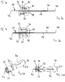
- the medical syringe 1 with needle retraction which is used in its entirety in 1 shown in longitudinal section, comprises an actuating plunger 4 and a hollow body 6 which is designed to be cylindrical or tubular in accordance with a conventional design and forms the syringe housing and is provided for receiving the medicinal active substance.
- a connecting element 10 is formed on the front or distal end 8 of the hollow body 6, to which a needle holder 12 for a hollow needle 14 provided for injecting the active ingredient can be attached.
- the rear or proximal end 16 of the hollow body 6 forming the syringe housing, on which a counter or gripping plate 17 is formed in a manner known per se, is, on the other hand, movable within the hollow body 6 and adapted in terms of its outer dimensions to the inner contour of the hollow body 6 with a precise fit Piston or stopper 18 closable.
- the medical syringe 1 could in principle be designed as a syringe 1 pre-filled with the active ingredient or alternatively also be used in such a way that the syringe 1 can be used empty and filled with the active ingredient by drawing it up. With regard to the detailed design features described below, both types of use are considered equivalent and can be used as alternatives to one another.
- the syringe and in particular the hollow body 6 forming the syringe housing is designed for a particularly high level of tightness, so that when used as a prefilled syringe, a certain shelf life of the active substance stored therein can also be achieved.
- the material for the syringe housing or the this forming hollow body 6 is suitably selected, so that even high demands on the reliable temporary storage of the medicinal active substance, accompanied by a particularly high level of safety when handling the components, are taken into account.
- the syringe body 6 designed as a cylindrical hollow body can be made of PP or of cyclo-olefin copolymer (COC), with or without a barrier layer, but is particularly preferably made of the high-performance plastic cyclo-olefin polymer (COP) in an embodiment considered to be inventive. manufactured.
- This material is characterized by high breaking strength and glass-like transparency. In addition, it does not release any alkali ions, so that the risk of a pH value shift in the active ingredient stored is excluded.
- the syringe body 6 is preferably manufactured using the injection molding process, with the shaping taking place, among other things, in such a way that possible dead volumes in the interior are kept particularly small.
- the hollow body 6 is also designed to be suitable for the intended high level of tightness and thus protection against unintentional loss of material due to the geometric design and shape of its components. This is taken into account in the area of the distal end 8 in particular by the configuration of the geometry of the connecting element 10 and the component connection formed by this together with the needle holder 12, which is considered to be independently inventive.
- the needle holder 12 can be plugged onto the hollow body 6 forming the syringe housing or the syringe cone, or alternatively it can also be screwed by means of a thread, for example a Luer thread. Both variants are considered to be equivalent alternatives in the present case, with the relevant design of the connection being considered to be interchangeable and freely selectable with regard to other boundary conditions, for example the intended subsequent handling.
- a thread for example a Luer thread.
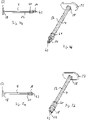
- Figure 2b a longitudinal section of a hollow body 6' forming the syringe housing is shown, the connecting element 10 of which is provided with a holding contour having a latching edge 22, for example in the form of an external hexagon, for producing a clip, push-on or snap-on connection.
- the connecting element 10 each has an inner channel 24 provided for connection to the needle holder 12 , which has an inner cross section that widens continuously outwards, i.e. towards the distal end 8 .
- the inner channel 24 is designed in the manner of a cone that widens toward the free end and has an at least approximately circular diameter.
- the cone angle is suitably selected with regard to the intended sealing effect, which will be explained in more detail below; With regard to the preferably selected material pairing of the hollow body 6 and the needle holder 12, the cone angle is preferably about 2°.
- the needle holder 12 carrying the hollow needle 14 is in 3 shown in detail in longitudinal section, namely in Figure 3a in one for the screw connection and in Figure 3b Variant intended for the clip or plug connection. It has a bearing sleeve 30 for the hollow needle 14 in each case. This has a conically designed contact surface 32 that is adapted in terms of its dimensioning, ie with respect to its cross-sectional area, its diameter and its cone angle, to the inner channel 24 of the connecting element 10 and can be inserted into the latter.
- the needle holder 12 and/or its stopper 30 can be designed as one or more components, in particular as two components.
- connection system With the specified configuration of the connection system, a particularly high sealing effect can be achieved with targeted use of the conical configuration of the connection surfaces, with which the inner channel 24 is closed by the needle holder 12 .
- the actual fixation on the connecting element 10 then takes place at the in Figure 3a shown variant of the screw connection by means of an integrated into the needle holder 12, adapted to the external thread 20 and thus also as a Luer thread or fine thread configured internal thread 34 and at the in Figure 3b shown variant of the clip or plug connection by means of an inner contour adapted to the holding contour, in the exemplary embodiment a hexagon socket 36.
- the design of the hollow needle 14 and its fixation in the bearing sleeve 30 essentially correspond to the design in FIG EP 3 738 629 A1 described system. Analogous to this, the bearing sleeve 30 is also provided with a circumferential fixing lip 38 in the present case.
- the hollow needle 14 includes a needle tube 40 made of metal, which forms a needle tip 42, 44 at each of its two ends.
- the choice of material for the needle tube 40 is preferably made with a view to common requirements for medical applications, a rustproof material that can also be used for standard needles, in particular high-grade steel, being particularly preferred.
- the needle tube 40 In its mid-length region, the needle tube 40 is encased and surrounded or encapsulated by a plastic jacket 46 .
- the material for the plastic jacket 46 is preferably a polyamide (PA12), particularly preferably the one commercially available under the name Vestamid Care ML 17.
- PA12 polyamide
- the plastic jacket 46 is sprayed onto the needle tube 40 after this has been subjected to a plasma pretreatment in the manner of surface activation. A particularly good adhesion of the plastic forming the plastic casing 46 on the needle 40 can thus be achieved.
- a retaining groove 48 is formed in the plastic jacket 46 and serves to temporarily fix the needle 14 in the bearing sleeve 30 of the needle holder 12 .
- the fixing lip 38 of the bearing sleeve 30 engages in the holding groove 48 and fixes it in the longitudinal direction.
- the dimensions of the retaining groove 48 and the fixing lip 38 are chosen such that, taking into account the deformability of the material of the plastic jacket 46, the encapsulated needle 14 can be pushed into the bearing sleeve 30 and clipped or latched in there.
- the plastic jacket 46 is designed in its end region facing the inside needle tip 42 to form a latching edge 50 or a number of latching elements, for example latching hooks or the like.
- the drive or actuating plunger 4 shown with the plug 18 attached comprises a shaft 56 which is provided with a push plate 52 at one end and on the other hand with a gripping bracket 54 provided for receiving the hollow needle 14 at its end opposite the push plate 52
- Shaft 56 also has a number of stop and latching elements which, in the exemplary embodiment, are arranged as adjusting rings 58, 60, namely a first adjusting ring 58 arranged proximally in the area of the shank 56 adjacent to the push plate 52 and a first adjusting ring 58 arranged distally in the area of the shank 56 adjacent to the gripping bracket 54 second adjusting ring 60, are executed. Design and functioning of these stop and locking elements are explained in more detail below.
- the medical syringe 1 is provided with a needle guard embodied in the manner of a retraction system by means of the components and parts mentioned.
- the purpose of this is that after the syringe 1 has been used, i.e. after the active substance stored in the hollow body 6 forming the syringe housing has been dispensed via the needle 14, it is drawn into the syringe housing in such a way that it is completely surrounded by the syringe housing. This is intended to keep the used needle 14 unintentionally touched, for example by auxiliary or nursing staff, and thus the risk of injury and contamination particularly low or, if possible, completely ruled out.
- the medical syringe 1 is to a substantially the execution of in the EP 3 738 629 A1 system described corresponding retraction system provided.
- the gripping bracket 54 is provided in the center with a needle bearing 62 forming a receiving hole for the needle 14, into which the inside needle tip 42 can be inserted and locked by means of the locking edge 50 or other suitable locking means.
- the needle bearing 62 is, like the bearing sleeve 30 described above, provided on the inside with an associated circumferential locking lip, which engages in the retaining groove formed by the locking edge 50 when the needle tip 42 is pushed into the needle bearing 62 and thus fixes the needle 14 in the longitudinal direction.
- the dimensions of the retaining groove and the locking lip associated with it in needle bearing 62 are selected in such a way that, taking into account the deformability of the material of plastic casing 46 and/or any adhesive force due to the material pairing of the material of plastic casing 46 and the material of needle bearing 62 surrounding it
- the holding or breaking force of the needle 14 locked in this way is greater in the longitudinal direction than the corresponding holding or breaking force of the fixing lip 38 in the bearing sleeve 30, so that when the stopper 18 retracts into the interior of the hollow body 6, 6', the needle 14 moves towards the interior of the hollow body 6.6' is taken along.
- the gripping bracket 54 is designed as a plastic part and consists in the exemplary embodiment with regard to the required holding forces and the mechanical loads expected during intended use, but also with regard to approval-related requirements, from the "Bormed TM " (HD810MO), ISO 10993 Information (Biocompatibility)) available polypropylene or alternatively from other pharmaceutical grade polyolefins with the appropriate suitability.
- the design of the gripping bracket 54 in combination with the plug 18 surrounding it creates a free space 64 within the plug 18, which in the final phase of the application of the active substance, in which the needle tip 42 has already penetrated the needle bearing 62 and is therefore suitable for the Active substance is no longer readily accessible, allowing the active substance to flow into the needle tube 40 via the needle tip 42 in the manner of a bypass.
- the inflow can take place on both sides of the gripping bracket 54 into the free space 64 .
- the stopper 18, which thus functions as a piston skirt is advantageously made of conventional rubber, particularly preferably of the material available from the Kreiburg company under the designation TM4RST (MC/RS Series), taking into account approval-related requirements.
- the plug 18 is shaped in such a way that when the gripping clip 54 is inserted, it leaves inflow channels free for the active ingredient on both sides of the gripping clip 54, so that the bypass for the desired zero-volume ejection is formed in the sense of avoiding or minimizing the dead volume.
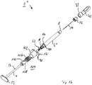
- a removable protective cap 70 for the needle 14 which is removed before the syringe 1 is used. this in 6
- the protective cap 70 shown is designed as a so-called tamper-evident closure in the manner of a one-way closure.
- This configuration as a one-way or tamper-evident closure allows problem-free and reliable identification as to whether the syringe 1 has already been used for liquid transfer or not, and thus makes it easier to determine whether the syringe 1 still meets the requirement of sterility or compliance with the sterile barrier, for example not, or whether - when used as a pre-filled syringe - the supply of active ingredient contained therein has already been "opened” or not.
- the protective cap 70 is cohesively connected to a tear-off ring or securing ring 73 via a number of connecting webs 72, ie, for example, molded or cast on.
- the tear-off or safety ring 73 can be clipped onto the needle holder 12 in a latching manner. To remove the protective cap 70, it must therefore be broken off the tear-off or safety ring 73, with the connecting webs 72 being severed beyond repair.
- the protective cap 70 forming the tamper-evident closure is made of two components in the exemplary embodiment and includes the actual cap housing 74 (preferably made of PP) and a control panel 76 (preferably made of TPE).
- the protective cap 70 must be removed by breaking it off.
- the syringe 1, as in 8 shown ready for use As a first step, the syringe 1 could be provided with a pre-filled hollow body 6, ie as a pre-filled syringe, be used. In this case the system is in the in 8 shown state already ready to dispense the active ingredient.
- the syringe 1 is made ready for use when empty and is filled with the active ingredient by drawing it up.
- the operating plunger 4 is first pressed by the operator so that the plug 18 within the hollow body 6 moves towards its distal end 8 .
- this movement is stopped by a stop.
- Syringe 1 in this position is in 9 shown in longitudinal section.
- the stop is formed in an embodiment considered to be independently inventive by the interaction of the proximal adjusting ring 58 with a snap-in receptacle 80 formed on the outside of the gripping plate 17 of the hollow body 6 .
- the locking receptacle 80 comprises a number of ring segments 82 which form a guide contour as a whole and are integrally formed on the gripping plate 17, which form a circumferential contour that is not completely continuous while forming gaps.
- detent hooks 84 that can be bent outwards are arranged in each case, which in each case form a stop surface for the proximal adjusting ring 58 on their upper side 86 .
- the plug 18 When the plug 18 is pushed into the interior of the hollow body 6, the user or operator can feel the impact of the proximal adjusting ring 58 on the upper side 86 of the locking hooks 84, so that he can see the push-in movement in the 9 shown position.
- the positioning of the adjusting ring 58 on the shaft 56 is chosen such that the stopper 18 is still far enough away from the needle tip 42 so that the latching edge 50 cannot penetrate into the needle bearing 62 in the gripping bracket 54. This ensures that an unintentional "too early" triggering of the retraction mechanism can be avoided.
- the exposed distal needle tip 44 of the needle 14 can now be inserted into an external reservoir of drug, such as a vial or drug container.
- the plug 18 is then pulled back in the hollow body 6 by means of the actuating plunger 4 .
- the active ingredient is sucked in via the needle 14 and the interior of the hollow body 6 is thus filled.
- the needle 14 for administering the medicinal agent is suitably positioned on the patient so that it pierces the patient's skin at a suitable point.
- the holding force of the needle 14 in the bearing sleeve 30 is specified, in particular as described above by the suitable dimensioning of the components and/or the choice of material pairing, in such a way that the needle 14 remains securely in its position in the bearing sleeve 30 when the operator by handling the hollow body 6, the needle 14 pierces the skin of the patient.
- the operator then presses the actuating plunger 4 so that the piston or stopper 18 moves within the hollow body 6 towards its distal end 8 and in the process supplies the medicinal substance to the needle 14 and dispenses it via it.
- the stopper 18 near the distal end 8 of the hollow body 6 reaches the needle tip 42 of the needle 14 protruding into the interior, so that, with further movement, the needle the receiving hole provided for this purpose in the needle bearing 62 of the gripping bracket 54 penetrates.
- the system thus again takes the already in 9 shown position, in which the proximal adjusting ring 58 hits the surface 86 of the locking hook 84. Again, the operator perceives this haptically.
- the full application of the active ingredient is now planned.
- the operator applies a slightly increased force to further advance the plug 18 in the hollow body 6, the latching hooks 84 due to suitable shaping and contouring on its surface to the outside, so that the adjusting ring 58 overcomes the aforesaid stop.
- the plug then reaches 18, as is shown in longitudinal section in 11 shown, then its end position (or also the "zero position") directly at the distal end 8 of the hollow body 6.
- the needle bearing 62 encloses the end part of the hollow needle 14 protruding into the receiving hole, with the locking lip running around the inside of the needle bearing 62 in the through the latching edge 50 engages in the retaining groove formed in the plastic casing 46 of the injection-molded needle and thus fixes the needle 14 in the longitudinal direction.
- This introduction of the corresponding partial area of the hollow needle 14 into the needle bearing 62 and the resulting connection of the needle 14 to the gripping clip 54 is also referred to here as "connecting".
- the combination of the free space formed in the stopper 18 by the interaction with the design of the gripping bracket 54, i.e. the aforementioned bypass, with the inner channel 24 in the needle holder 12, which widens outwards in the manner of a cone, is considered to be independently inventive.
- a continuous, uniform application of the active substance can also be made possible in the final phase when administering the active substance, while minimizing any dead volume, so that continuous injection and highly precise dosing of the active substance can be guaranteed even for the residual amounts of the active substance to be administered , without the feed force required for the further movement of the actuating plunger 4 having to be changed.
- the operator pulls back the pusher plate 52 and with it the actuating plunger 4 as a whole.
- the stopper 18 arranged at the end of the shaft 56 is also taken along and pulled within the hollow body 6 away from the distal end 8 towards the proximal end 16 .
- he for his part takes along the needle 14 which is enclosed and fixed in the gripping bracket 54 and pulls it into the hollow body 6 so that in the final state it is positioned completely within the hollow body 6 .
- This position is in longitudinal section in 12 shown.
- the needle 14 is safely stored within the hollow body 6 and is completely surrounded by it, so that the needle 14 no longer poses a risk to personnel or operators, for example through accidental pricking.
- the second, distal adjusting ring 60 is provided, which is suitably latched with a latching element arranged on the hollow body 6 .
- the flange-side adjusting ring 60 is thus securely anchored to the hollow body 6, and the needle 14 located in the hollow body 6 cannot be pulled, pushed or pushed forwards or backwards.
- the suitable dimensioning of the components and/or any adhesive force due to the material pairing of the material of the plastic jacket 46 and the material of the bearing sleeve 30 surrounding it increases the holding or breakaway force of the needle 14 locked in this way in the longitudinal direction on the one hand is sufficiently large so that the needle 14 can be inserted into the patient's skin in accordance with the procedure described above, but on the other hand it is also sufficiently small so that the described retraction movement of the needle 14 towards the interior of the hollow body 6 can be carried out.
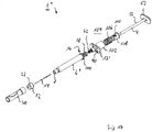
- the medical syringe 1 is equipped with an RFID chip 90, in particular for the purpose of setting up digitized logistics, an automatable transport system for syringes, for quality or product control and/or for other recording or monitoring purposes , which can have, for example, an individualized, machine-readable coding.
- an RFID chip 90 is positioned on the handle plate 17 molded onto the hollow body 6 .
- the finger rest 92 is made of PP.
- a medical syringe 1' with an RFID chip 90 in the area of its grip plate 17 in this way is considered to be inventive in its own right. Accordingly, in 15 a medical syringe 1' designed as a standard syringe with a conventional actuating plunger 4 and a conventional hollow body 6 forming the syringe housing, which is equipped with such an RFID chip 90 on its gripping plate 17.
- This variant of the medical syringe 1′ can, of course, also be equipped with the protective cap 70 designed as a tamper-evident closure.
- the medical syringe 1 described above is equipped with a retraction system, in which the operator can retract the needle 14 completely into the hollow body 6 forming the syringe housing after the active substance has been completely dispensed.
- a retraction system in which the operator can retract the needle 14 completely into the hollow body 6 forming the syringe housing after the active substance has been completely dispensed.
- the actuating plunger 4 together with the stopper 18 arranged at the end and the needle bearing 62 enclosed by it in which the needle 14 is fixed after the "connecting" must be carried out manually or in the form of an active action be pulled back by the operator until the distal adjusting ring 60 is locked in the manner described with the hollow body 6.
- This type of retraction system is therefore also referred to as "active retraction”.
- a medical syringe 1" can also be equipped with a "passive" retraction system suitable for "passive retraction", as its basic mode of operation is based on, for example, from EP 3 738 628 A1 is known.
- a passive retraction system with one or more of the features or feature groups described above, in particular with the design of the connection to the needle holder 12, with the equipment with RFID chip 90, with the equipment of the actuating plunger 4 with the adjusting rings 58, 60 as Latching or stop elements and/or equipped with a protective cap 70 designed as a tamper-evident closure is considered to be independently inventive.
- the hollow body 6" forming the syringe housing is also designed as an alternative to the construction described above; it now comprises a separate gripping plate 17', which can be pushed onto a locking edge 100 running around its proximal end 16.
- the outer housing 102 of the retraction mechanism 104 is formed on its side facing away from the hollow body 6".
- the medical syringe 1 which is otherwise also analogous to that described above Design is provided with the tamper evident seal 70 is provided with the desired passive needle guard by the retraction mechanism 104.
- the purpose of this is that after the syringe 1" has been used, i.e. after the active substance stored in the hollow body 6" forming the syringe housing has been dispensed via the needle 14, the latter is drawn into the syringe housing in such a way that it is completely surrounded by the syringe housing. This is intended to keep the used needle 14 unintentionally touched, for example by auxiliary or nursing staff, and thus the risk of injury and contamination particularly low or, if possible, completely ruled out.
- the retraction mechanism 104 is constructed according to the functional principle that a compressed elastic spring 106 that is under pretension is locked by means of a locking element 108 .
- the locking element 108 is unlocked at a given time as a result of the advancement of the actuating plunger 4 and releases the elastic spring 106 so that it can relax and thereby pushes the actuating plunger 4 back.
- the design of the locking mechanism for the spring 106 is considered to be independently inventive.
- the locking mechanism is essentially based on the interaction of a number of the Control pins arranged on the inner surface of the outer housing 102, each with an associated guide slot 110 in the outer casing of the locking element 108.
- the control pin 112 engages in the guide slot 110 introduced into the outer casing of the locking element 108 .
- the guide link 110 has a bulge 114 on the side, into which the control pin 112 can be screwed.
- the bulge 114 is contoured in such a way that the control pin 112 is held in a form-fitting manner downwards, i.e. towards the hollow body 6′′, and therefore cannot deviate. In this state, in which the inner spring 106 is compressed, the system is thus locked and the coil spring 106 cannot relax.
- Unlocking can then take place in that the control pin 112 is rotated laterally by suitable control and is moved out of the bulge 114 . It thus comes to rest over a downwardly open channel 116 of the guide slot 110 so that it can now move downwards relative to the locking element 108 and is no longer positively blocked by the guide slot 110 . In this position, the locking element 108 can thus be displaced upwards relative to the outer housing 102, i.e. away from the hollow body 6", by the spring 106 without being blocked by the control pin 112, with the spring 106 relaxing.
- the spring relaxes and in doing so moves the pusher plate 52 of the actuating plunger 4 away from the syringe body formed by the hollow body 6". in which the needle 14 is already located in this phase, taken along and drawn within the hollow body 6" away from the distal end 8 towards the proximal end 16. In doing so, he in turn takes the mounted needle 14 with him and pulls it into the hollow body 6" so that in the final state it is positioned completely within the hollow body 6".
- the spring 106 provided for carrying out the retraction movement of the needle 14 into the hollow body 6" is arranged above the grip plate 17' in the area of the shaft 56 of the actuating plunger 4 and via its push plate 52 on the actuating plunger 4.
- the design now provided according to the invention means that the needle 14 is moved during retraction together with the actuating plunger 4 and in particular its pusher plate 52, so that the user or operator can use the position of the pusher plate 52 relative to the grip plate 17' to recognize the position and, above all, the change in position of the needle 14. This recognition is optical possible before but also haptic.
- the retraction movement similar to the actuation button of a ballpoint pen, generates a movement of the push plate 52 that the user can feel, for example with the thumb.
- This allows the user to conclude from the movement of the push plate 52 that can be felt with the thumb that the needle 14 has now retracted and there is therefore no longer any risk of injury or contamination in the area of the distal end 8 of the syringe 1".
- he can also conclude from this that the active substance has now been completely administered without having to monitor this visually, for example.
- the syringe 1" thus enables significantly simplified handling when administering the active ingredient.
Landscapes
- Health & Medical Sciences (AREA)
- Engineering & Computer Science (AREA)
- Heart & Thoracic Surgery (AREA)
- Vascular Medicine (AREA)
- Anesthesiology (AREA)
- Biomedical Technology (AREA)
- Hematology (AREA)
- Life Sciences & Earth Sciences (AREA)
- Animal Behavior & Ethology (AREA)
- General Health & Medical Sciences (AREA)
- Public Health (AREA)
- Veterinary Medicine (AREA)
- Environmental & Geological Engineering (AREA)
- Infusion, Injection, And Reservoir Apparatuses (AREA)
Priority Applications (3)
| Application Number | Priority Date | Filing Date | Title |
|---|---|---|---|
| EP20212250.3A EP4008380A1 (fr) | 2020-12-07 | 2020-12-07 | Seringue médicale |
| US18/265,693 US20240024586A1 (en) | 2020-12-07 | 2021-12-06 | Medical syringe |
| PCT/EP2021/084454 WO2022122677A2 (fr) | 2020-12-07 | 2021-12-06 | Seringue médicale |
Applications Claiming Priority (1)
| Application Number | Priority Date | Filing Date | Title |
|---|---|---|---|
| EP20212250.3A EP4008380A1 (fr) | 2020-12-07 | 2020-12-07 | Seringue médicale |
Publications (1)
| Publication Number | Publication Date |
|---|---|
| EP4008380A1 true EP4008380A1 (fr) | 2022-06-08 |
Family
ID=73740311
Family Applications (1)
| Application Number | Title | Priority Date | Filing Date |
|---|---|---|---|
| EP20212250.3A Withdrawn EP4008380A1 (fr) | 2020-12-07 | 2020-12-07 | Seringue médicale |
Country Status (3)
| Country | Link |
|---|---|
| US (1) | US20240024586A1 (fr) |
| EP (1) | EP4008380A1 (fr) |
| WO (1) | WO2022122677A2 (fr) |
Families Citing this family (1)
| Publication number | Priority date | Publication date | Assignee | Title |
|---|---|---|---|---|
| USD987074S1 (en) * | 2021-06-21 | 2023-05-23 | Legacy Medical Innovations LLC | Syringe |
Citations (9)
| Publication number | Priority date | Publication date | Assignee | Title |
|---|---|---|---|---|
| EP0680347B1 (fr) | 1992-05-15 | 1998-04-15 | Safe-T-Limited | Seringue a aiguille retractable |
| EP0720491B1 (fr) | 1993-09-22 | 2003-08-20 | SHAW, Thomas J. | Dispositif medical non reutilisable avec retraction frontale |
| EP1284769B1 (fr) | 2000-05-05 | 2005-11-16 | Safety Syringes, Inc. | Gaine passive pour seringues |
| WO2006047810A1 (fr) * | 2004-11-04 | 2006-05-11 | Global Medisafe Holdings Pty Limited | Seringue de securite retractable a changement d’aiguille |
| EP1764127B1 (fr) | 2005-08-08 | 2008-02-27 | Smiths Medical ASD, Inc. | Capuchon de protection pour aiguilles avec talon |
| US20090062745A1 (en) * | 2007-08-31 | 2009-03-05 | Can-Long Qiu | Safety Syringe |
| US20150148748A1 (en) * | 2013-11-15 | 2015-05-28 | Credence Medsystems, Inc. | System and method for drug delivery with a safety syringe |
| EP3738629A1 (fr) | 2019-05-16 | 2020-11-18 | Trenta2 S.r.l. | Seringue médicale à protection d'aiguille |
| EP3738628A1 (fr) | 2019-05-16 | 2020-11-18 | Trenta2 S.r.l. | Seringe médical avec système passive de protection d'aiguilles |
-
2020
- 2020-12-07 EP EP20212250.3A patent/EP4008380A1/fr not_active Withdrawn
-
2021
- 2021-12-06 US US18/265,693 patent/US20240024586A1/en not_active Abandoned
- 2021-12-06 WO PCT/EP2021/084454 patent/WO2022122677A2/fr not_active Ceased
Patent Citations (9)
| Publication number | Priority date | Publication date | Assignee | Title |
|---|---|---|---|---|
| EP0680347B1 (fr) | 1992-05-15 | 1998-04-15 | Safe-T-Limited | Seringue a aiguille retractable |
| EP0720491B1 (fr) | 1993-09-22 | 2003-08-20 | SHAW, Thomas J. | Dispositif medical non reutilisable avec retraction frontale |
| EP1284769B1 (fr) | 2000-05-05 | 2005-11-16 | Safety Syringes, Inc. | Gaine passive pour seringues |
| WO2006047810A1 (fr) * | 2004-11-04 | 2006-05-11 | Global Medisafe Holdings Pty Limited | Seringue de securite retractable a changement d’aiguille |
| EP1764127B1 (fr) | 2005-08-08 | 2008-02-27 | Smiths Medical ASD, Inc. | Capuchon de protection pour aiguilles avec talon |
| US20090062745A1 (en) * | 2007-08-31 | 2009-03-05 | Can-Long Qiu | Safety Syringe |
| US20150148748A1 (en) * | 2013-11-15 | 2015-05-28 | Credence Medsystems, Inc. | System and method for drug delivery with a safety syringe |
| EP3738629A1 (fr) | 2019-05-16 | 2020-11-18 | Trenta2 S.r.l. | Seringue médicale à protection d'aiguille |
| EP3738628A1 (fr) | 2019-05-16 | 2020-11-18 | Trenta2 S.r.l. | Seringe médical avec système passive de protection d'aiguilles |
Also Published As
| Publication number | Publication date |
|---|---|
| WO2022122677A3 (fr) | 2022-08-04 |
| WO2022122677A2 (fr) | 2022-06-16 |
| US20240024586A1 (en) | 2024-01-25 |
Similar Documents
| Publication | Publication Date | Title |
|---|---|---|
| DE60107167T2 (de) | Hypodermische Spritze mit selektiv zurückziehbarer Nadel | |
| DE69926675T2 (de) | Schnittstelle zwischen einem Phiolebehälter und einer stiftförmigen Medikamentenspritze | |
| DE60102526T2 (de) | Hypodermische Spritze mit selektiv zurückziehbarer Nadel | |
| DE102004060146C5 (de) | Autoinjektor mit Arretierung des Wirkstoffbehälters | |
| DE69502357T2 (de) | Injektionsmodul für eine spritze | |
| DE60102517T2 (de) | Hypodermische Spritze mit selektiv zurückziehbarer Nadel | |
| DE60109546T2 (de) | Hypodermische Spritze mit selektiv zurückziehbarer Nadel | |
| EP3659653B1 (fr) | Auto-injecteur avec mode de déclenchement sélectionnable | |
| DE60029556T2 (de) | System zur Verabreichung von Arzneimittlen mit einem Arzneimittelbehälter und dessen Halterung | |
| EP2063937B1 (fr) | Dispositif de protection d'aiguille présentant une position de protection bloquée | |
| DE60101307T2 (de) | Medizinische vorrichtung und verriegelungsmechanismus dafür | |
| DE69918493T2 (de) | Schutzhülse für vorgefüllte Spritzen | |
| DE60105233T2 (de) | Subkutaninjektionsspritze mit selektiv einziehbarer Nadel | |
| DE69410905T2 (de) | Aus Kartusche und Nadel bestehende Einheit mit rückziehbarer Nadel | |
| DE602004013125T2 (de) | Sicherheits-nadelschutz für spritzen | |
| EP3738629B1 (fr) | Seringue médicale à protection d'aiguille | |
| EP4126118A1 (fr) | Auto-injecteur pourvu d'un récipient de produit à chambres multiples | |
| EP0652027A1 (fr) | Dispositif d'injection | |
| DE10348185A1 (de) | Injektionsgerät mit Nadelabdeckung | |
| WO2018018164A1 (fr) | Dispositif d'injection doté d'un capuchon protecteur et d'un dispositif empêchant le repositionnement du capuchon protecteur | |
| DE102005043805A1 (de) | Zentrierhilfe zum Aufsetzen einer Nadel auf ein Injektionsgerät | |
| WO2022122677A2 (fr) | Seringue médicale | |
| EP3738628A1 (fr) | Seringe médical avec système passive de protection d'aiguilles | |
| EP4380666A1 (fr) | Dispositif d'application pour au moins un implant | |
| WO2022053166A1 (fr) | Seringue médicale avec protection d'aiguille |
Legal Events
| Date | Code | Title | Description |
|---|---|---|---|
| PUAI | Public reference made under article 153(3) epc to a published international application that has entered the european phase |
Free format text: ORIGINAL CODE: 0009012 |
|
| STAA | Information on the status of an ep patent application or granted ep patent |
Free format text: STATUS: THE APPLICATION HAS BEEN PUBLISHED |
|
| AK | Designated contracting states |
Kind code of ref document: A1 Designated state(s): AL AT BE BG CH CY CZ DE DK EE ES FI FR GB GR HR HU IE IS IT LI LT LU LV MC MK MT NL NO PL PT RO RS SE SI SK SM TR |
|
| STAA | Information on the status of an ep patent application or granted ep patent |
Free format text: STATUS: REQUEST FOR EXAMINATION WAS MADE |
|
| 17P | Request for examination filed |
Effective date: 20221207 |
|
| RBV | Designated contracting states (corrected) |
Designated state(s): AL AT BE BG CH CY CZ DE DK EE ES FI FR GB GR HR HU IE IS IT LI LT LU LV MC MK MT NL NO PL PT RO RS SE SI SK SM TR |
|
| STAA | Information on the status of an ep patent application or granted ep patent |
Free format text: STATUS: EXAMINATION IS IN PROGRESS |
|
| 17Q | First examination report despatched |
Effective date: 20241030 |
|
| STAA | Information on the status of an ep patent application or granted ep patent |
Free format text: STATUS: THE APPLICATION IS DEEMED TO BE WITHDRAWN |
|
| 18D | Application deemed to be withdrawn |
Effective date: 20250301 |