EP4008419B1 - Installation de traitement des eaux usées - Google Patents
Installation de traitement des eaux usées Download PDFInfo
- Publication number
- EP4008419B1 EP4008419B1 EP21210368.3A EP21210368A EP4008419B1 EP 4008419 B1 EP4008419 B1 EP 4008419B1 EP 21210368 A EP21210368 A EP 21210368A EP 4008419 B1 EP4008419 B1 EP 4008419B1
- Authority
- EP
- European Patent Office
- Prior art keywords
- waste water
- compressed air
- treatment plant
- curved section
- pipeline
- Prior art date
- Legal status (The legal status is an assumption and is not a legal conclusion. Google has not performed a legal analysis and makes no representation as to the accuracy of the status listed.)
- Active
Links
Images
Classifications
-
- C—CHEMISTRY; METALLURGY
- C02—TREATMENT OF WATER, WASTE WATER, SEWAGE, OR SLUDGE
- C02F—TREATMENT OF WATER, WASTE WATER, SEWAGE, OR SLUDGE
- C02F3/00—Biological treatment of water, waste water, or sewage
- C02F3/02—Aerobic processes
- C02F3/12—Activated sludge processes
- C02F3/1236—Particular type of activated sludge installations
- C02F3/1263—Sequencing batch reactors [SBR]
-
- C—CHEMISTRY; METALLURGY
- C02—TREATMENT OF WATER, WASTE WATER, SEWAGE, OR SLUDGE
- C02F—TREATMENT OF WATER, WASTE WATER, SEWAGE, OR SLUDGE
- C02F2203/00—Apparatus and plants for the biological treatment of water, waste water or sewage
- C02F2203/006—Apparatus and plants for the biological treatment of water, waste water or sewage details of construction, e.g. specially adapted seals, modules, connections
-
- C—CHEMISTRY; METALLURGY
- C02—TREATMENT OF WATER, WASTE WATER, SEWAGE, OR SLUDGE
- C02F—TREATMENT OF WATER, WASTE WATER, SEWAGE, OR SLUDGE
- C02F2209/00—Controlling or monitoring parameters in water treatment
- C02F2209/42—Liquid level
-
- C—CHEMISTRY; METALLURGY
- C02—TREATMENT OF WATER, WASTE WATER, SEWAGE, OR SLUDGE
- C02F—TREATMENT OF WATER, WASTE WATER, SEWAGE, OR SLUDGE
- C02F2301/00—General aspects of water treatment
- C02F2301/02—Fluid flow conditions
- C02F2301/028—Tortuous
-
- Y—GENERAL TAGGING OF NEW TECHNOLOGICAL DEVELOPMENTS; GENERAL TAGGING OF CROSS-SECTIONAL TECHNOLOGIES SPANNING OVER SEVERAL SECTIONS OF THE IPC; TECHNICAL SUBJECTS COVERED BY FORMER USPC CROSS-REFERENCE ART COLLECTIONS [XRACs] AND DIGESTS
- Y02—TECHNOLOGIES OR APPLICATIONS FOR MITIGATION OR ADAPTATION AGAINST CLIMATE CHANGE
- Y02W—CLIMATE CHANGE MITIGATION TECHNOLOGIES RELATED TO WASTEWATER TREATMENT OR WASTE MANAGEMENT
- Y02W10/00—Technologies for wastewater treatment
- Y02W10/10—Biological treatment of water, waste water, or sewage
Definitions
- Such sequentially operating wastewater treatment plants also known as SBR plants (SBR - Sequencing Batch Reactor), work in the activated sludge process in impoundment mode.
- Air is introduced into the reactor vessel in the form of fine bubbles using the aeration device.
- the aeration ensures that the bacteria are supplied with oxygen for biological purification.
- Wastewater treatment using the activated sludge process in SBR plants is divided into the following phases, which together form a cycle:
- the wastewater to be treated either first enters the primary clarification chamber, in which solid components are retained, or is discontinuously fed directly into the reactor vessel of the single-vessel plant.
- the biological purification of the wastewater takes place in the reactor vessel. Air is introduced into the reactor vessel using the aeration device. The so-called activated sludge with microorganisms is created and the wastewater is circulated and biologically purified by the introduction of air.
- the activated sludge sinks to the bottom of the reactor vessel. This creates a clear water zone in the upper part of the reactor vessel.
- the treated wastewater from the clear water zone is drained off with a clear water outlet and discharged into a receiving water body or an infiltration system.
- From the EN 10 2014 103 652 is a single-tank plant for wastewater treatment using the activated sludge process in impoundment operation with aerobic sludge stabilization.
- the Single tank system works with one cycle per day.
- the waste water is fed in during the filling phase via an extended immersion pipe to calm the inflow.
- the air is introduced in the reaction phase using several tubular membrane aerators arranged in a star shape.
- a submersible motor pump is used to remove clear water during the decanting phase and is arranged in a vacuum tank.
- Another single-tank system for wastewater treatment using the activated sludge process in impoundment operation with aerobic sludge stabilization from KLARO is from small sewage treatment plants today, Bernd Goldberg, 3rd, completely revised and expanded edition 2018, Beuth Verlag GmbH, pages 365 - 367
- the single-tank system has a submersible wall for attaching a mammoth pump for clear water removal.
- Two membrane aerators are arranged at the bottom of the reactor vessel to introduce air into the wastewater.
- the single-tank system operates with 2 to 5 cycles per day.
- a discharge device which is movably arranged in the reactor vessel and has a discharge inlet for the treated wastewater and a fluid-conducting connection between the discharge inlet of the discharge device and the outlet, as well as a ventilated and ventable lifting device for the discharge device, which completely lifts the discharge inlet of the discharge device out of the wastewater by ventilating and immerses the discharge inlet of the discharge device in the wastewater by venting.
- the ventilated lifting device prevents wastewater and stirred-up activated sludge flocs from escaping from the reactor vessel during the reaction and settling phase. By venting the lifting device, the discharge device immerses the discharge inlet in the wastewater due to its own weight and the treated wastewater from the clear water zone flows freely through the outlet.
- a gas connection is provided for introducing and discharging a pressurized gas.
- the introduction creates a gas bubble in the channel, which prevents the liquid from flowing from the first to the second chamber.
- the pressurized gas is released from the pipeline channel so that the liquid can flow through the pipeline again unhindered.
- a drain chamber is arranged in the second chamber, which is formed by a container that is open at the top and is immersed in the liquid within the chamber. In the upper area, the container is connected to the drain so that the liquid in the container can drain through the drain when the liquid level in the container falls to the level of the drain increases.
- the overflow or transfer of the liquid from the second chamber into the container takes place in the same way as the transfer of the water from the first chamber into the second chamber with a U-shaped pipe, whereby an overflow of liquid from the second chamber into the container can be prevented by means of an air bubble in the apex area.
- Multi-chamber small sewage treatment plants are known in which different chambers of the sewage treatment plant are connected to each other by U-shaped pipes according to the principle of communicating tubes. Air bubbles rising from a submersible aerator for the aeration air enter the pipe and interrupt its function as a communicating tube.
- the DE 20 2012 004597 U1 a siphon device in which an upper siphon bend section is coupled to a compressed air line, wherein the siphon device can be ventilated via the compressed air line in order to form an air bubble which prevents the overflow of the pre-treated wastewater from the primary clarifier into the reactor tank, and wherein the siphon device can be ventilated via the compressed air line in order to be able to release the air bubble, so that the overflow is made possible.
- the siphon device is formed by known and commercially available pipes and bends; it has an inlet pipe with a drain inlet, to which the upper siphon bend section is connected. One pipe connects the upper siphon bend section to a lower siphon bend section. Another pipe connects the lower siphon bend section to a second upper Siphon bend section. This is followed by an outlet pipe.
- the interior of the first curved section can be temporarily pressurized with compressed air from a compressed air source or temporarily vented via the at least one working line.
- the pressurization of compressed air builds up the gas bubble and prevents further liquid from being drawn off. By venting, the fluid-conducting connection becomes continuous and the liquid can be drawn off.
- the vertical distance between the second curved section and the surface of the minimum wastewater level (H W min ) is at least the distance between the maximum wastewater level (H W max ) and the minimum wastewater level (H W min ).
- the connecting section of the pipeline connecting the first curved section and the second curved section of the pipeline preferably, but not necessarily, runs in a vertical direction. The only important thing is to maintain the vertical distance between the second curved section and the surface of the minimum wastewater level (H W min ).
- a significant advantage of the solution according to the invention is that the design prevents contamination of the shut-off device, so that even if sludge or other contaminants are accidentally sucked in, no operational disruptions to the wastewater treatment plant are to be expected. This significantly improves the reliability of the wastewater treatment plant.
- the compressed air source via which the interior of the curved section of the fluid-conducting connection can be temporarily pressurized with compressed air, is preferably a compressor.
- a compressed air bottle or a pressure pipe network to which the wastewater treatment plant can be connected can also serve as the compressed air source.
- At least one A working line is provided which opens into the curved section of the fluid-conducting connection and via which the interior of the curved section can be temporarily pressurised or vented with compressed air from the compressed air source.
- This temporary venting and venting of the curved section can be achieved in a structurally simple and low-cost manner using a 3/2-way valve and a control system for temporarily activating/deactivating the compressed air source.
- the compressed air source is connected to a compressed air connection and the working line to a working line connection of a 3/2-way valve, which also has a throttled vent connection.
- the path for the compressed air between the compressed air connection and the working line connection and the path between the working line connection and the throttled vent connection are open.
- the throttled vent connection is designed in such a way that in the first switching position, when the compressed air source is activated, it temporarily supplies the interior of the curved section with compressed air and thus closes it off.
- the compressed air source is deactivated in the first switching position, the curved section of the fluid-conducting connection is vented.
- this first switching position when the compressed air source is activated via the throttled vent connection, there are small compressed air losses, which, however, are negligible in view of the short ventilation phases for shutting off the drain device.
- the flow resistances in the compressed air line system are designed in such a way that in the first switching position at When the compressed air source is activated, the fluid connection of the drain device is first shut off and only then is the ventilation device ventilated. This prevents untreated wastewater from being stirred up before the shut-off and reaching the outlet via the drain device.
- the control for the temporary operation of the compressed air source has a measuring device for detecting the level of the waste water in the reactor vessel.
- the control is set up in such a way that the supply of compressed air is terminated prematurely if the level of the waste water detected by the measuring device exceeds a predetermined limit value, in particular the maximum waste water level (H W max ).
- the supply of compressed air can be terminated prematurely by deactivating the compressed air source using the control or by interrupting the compressed air line.
- a mechanical level measurement is carried out, for example, with a float on the waste water level of the waste water, which moves a switch or displacement sensor.
- the height of the water level can be detected contactlessly, for example inductively or by means of a Pressure difference measurement.
- the inflowing wastewater is preferably introduced into the tank in a calmed manner, in which an inlet for the untreated wastewater is arranged at the inlet and the outlet is located below the surface of the minimum wastewater level (H W min ).
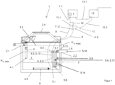
- a double U-shaped drainage device (5) comprises a drainage inlet (5.1) for the treated waste water and a fluid-conducting connection between the drainage inlet (5.1) and the outlet (2.2).
- the fluid-conducting connection is designed as a pipe (5.2).
- the cycle begins with the filling phase and reaction phase from the beginning, in which the control (12) reactivates the compressed air source (7) and brings the 3/2-way valve (11) into the first switching position so that the discharge direction (5) is blocked.
Landscapes
- Life Sciences & Earth Sciences (AREA)
- Biodiversity & Conservation Biology (AREA)
- Microbiology (AREA)
- Hydrology & Water Resources (AREA)
- Engineering & Computer Science (AREA)
- Environmental & Geological Engineering (AREA)
- Water Supply & Treatment (AREA)
- Chemical & Material Sciences (AREA)
- Organic Chemistry (AREA)
- Aeration Devices For Treatment Of Activated Polluted Sludge (AREA)
Claims (14)
- Station d'épuration (1) des eaux usées à fonctionnement séquentiel, destinée à l'assainissement biologique d'eaux usées (3), comprenant- une cuve de réacteur (2), pourvue d'un fond de réacteur (2.3), destinée à recevoir des eaux usées (3), la surface des eaux usées (3.1) fluctuant entre un niveau maximum (H W max) des eaux usées et un niveau minimum (H W min) des eaux usées,- une entrée (2.1) pour les eaux usées (3) non traitées, qui est placée au-dessus de la surface du niveau maximum (H W max) des eaux usées dans la cuve de réacteur (2),- une sortie (2.2) pour les eaux usées (3) traitées, qui est placée en-dessous de l'entrée (2.1) dans la cuve de réacteur (2) et au-dessus de la surface (3.1) du niveau minimum (H W min) des eaux usées,- un dispositif d'évacuation (5), placé dans la cuve de réacteur (2), pourvu d'une entrée de l'évacuation (5.1) pour les eaux usées (3) traitées, une liaison fluidique étant placée entre l'entrée de l'évacuation (5.1) du dispositif d'évacuation (5) et la sortie (2.2),- un dispositif d'aération (8) pour l'introduction d'air dans les eaux usées (3), qui est placé sur le fond inférieur de la cuve de réacteur (2), caractérisée en ce que- la liaison fluidique est une canalisation (5.2), l'entrée d'évacuation (5.1) se situe en-dessous de la surface du niveau minimum (H W min) des eaux usées et la station d'épuration des eaux usées comprend par ailleurs ce qui suit :- un tronçon (5.5) incurvé dans la canalisation (5.2), tourné vers le haut, en direction de la surface maximum (H W max) des eaux usées- un deuxième tronçon (5.6) incurvé dans la canalisation (5.2), tourné vers le bas, en direction du fond de réacteur (2.3), le deuxième tronçon (5.6) incurvé se trouvant en-dessous du premier tronçon (5.5) incurvé et en-dessous de la surface du niveau minimum (H W min) des eaux usées et l'écart vertical entre le deuxième tronçon (5.6) incurvé et la surface du niveau minimum (H W min) des eaux usées s'élevant au moins à l'écart compris entre le niveau maximum (H W max) des eaux usées et le niveau minimum (H W min) des eaux usées,- un tronçon de liaison (5.4) de la canalisation (5.2), qui relie l'un à l'autre le premier tronçon (5.5) incurvé et le deuxième tronçon (5.6) incurvé de la canalisation (5.2),- un tronçon d'entrée (5.3) de la canalisation (5.2), relié avec le premier tronçon (5.6) incurvé, qui comporte l'entrée d'évacuation (5.1),- un tronçon de sortie (5.8) de la canalisation (5.2), relié avec le deuxième tronçon (5.6) incurvé, qui relie le deuxième tronçon (5.6) incurvé avec la sortie (2.2),- au moins une conduite de travail (6), débouchant dans le premier tronçon (5.5) incurvé de la liaison fluidique (5.2), par l'intermédiaire de laquelle l'intérieur du tronçon (5.5) incurvé peut être soumis temporairement à de l'air comprimé émanant d'une source (7) d'air comprimé ou peut être temporairement purgé d'air.
- Station d'épuration des eaux usées selon la revendication 1, caractérisée en ce que le tronçon de liaison (5.4) de la canalisation (5.2) et / ou le tronçon d'entrée (5.3) de la canalisation (5.2) s'écoulent en direction verticale.
- Station d'épuration des eaux usées selon la revendication 1 ou 2, caractérisée en ce qu'en partant du deuxième tronçon (5.6) incurvé, le tronçon de sortie (5.8) de la canalisation (5.2) s'écoule d'abord en direction verticale et ensuite en direction horizontale.
- Station d'épuration des eaux usées selon l'une quelconque des revendications 1 à 3, caractérisée en ce que le premier et le deuxième tronçon (5.5, 5.6) incurvé est un collecteur.
- Station d'épuration des eaux usées selon l'une quelconque des revendications 2 à 4, caractérisée en ce que le tronçon de liaison (5.4) de la canalisation (5.2) et / ou le tronçon d'entrée (5.3) de la canalisation (5.2) sont des pièces tubulaires droites.
- Station d'épuration des eaux usées selon l'une quelconque des revendications 2 à 5, caractérisée en ce que le tronçon de sortie (5.8) de la canalisation (5.2) s'écoulant en direction verticale et celui s'écoulant en direction horizontale sont chacun des pièces tubulaires droites, qui sont reliées l'une à l'autre par l'intermédiaire d'un connecteur à 90 degrés.
- Station d'épuration des eaux usées selon l'une quelconque des revendications 1 à 6, caractérisée en ce que la source (7) d'air comprimé est un compresseur.
- Station d'épuration des eaux usées selon l'une quelconque des revendications 1 à 7, caractérisée en ce que le dispositif d'aération (8) est relié avec la source (7) d'air comprimé par l'intermédiaire d'une conduite (9) d'air comprimé.
- Station d'épuration des eaux usées selon l'une quelconque des revendications 1 à 8, comprenant par ailleurs- une soupape à 3/2 voies (11), pourvue d'un raccordement (11.1) d'air comprimé, d'un raccordement (11.2) sur la conduite de travail ainsi que d'un raccordement (11.3) de purge d'air étranglé,- la source (7) d'air comprimé est reliée avec le raccordement (11.1) d'air comprimé et la conduite de travail (6) est reliée avec le raccordement (11.2) sur la conduite de travail de la soupape à 3/2 voies (11),- dans une première position de commutation de la soupape à 3/2 voies (11), la voie pour l'air comprimé entre le raccordement (11.1) d'air comprimé et le raccordement (11.2) sur la conduite de travail et la voie entre le raccordement (11.2) sur la conduite de travail et le raccordement (11.3) de purge d'air étranglé sont ouvertes et dans une deuxième position de commutation, la voie pour l'air comprimé entre le raccordement (11.1) d'air comprimé et le raccordement (11.2) sur la conduite de travail et la voie entre le raccordement (11.2) sur la conduite de travail et le raccordement (11.3) de purge d'air étranglé sont fermées, le raccordement (11.3) de purge d'air étranglé étant conçu de telle sorte que dans la première position de commutation, lorsque la source (7) d'air comprimé est activée, l'intérieur du tronçon (5.5) incurvé soit temporairement soumis à de l'air comprimé et dans la première position de commutation, lorsque la source (7) d'air comprimé n'est pas activée, l'intérieur du tronçons (5.5) incurvé soit purgé d'air.
- Station d'épuration des eaux usées selon l'une quelconque des revendications 1 à 9, comprenant par ailleurs un système de commande (12), configuré pour une activation temporaire de la source (7) d'air comprimé.
- Station d'épuration des eaux usées selon la revendication 9 et 10, caractérisée en ce que la système de commande (12) est configuré indépendamment de l'activation de la source (7) d'air comprimé pour commander la soupape à 3/2 voies (11) actionnée électriquement.
- Station d'épuration des eaux usées selon l'une quelconque des revendications 1 à 11, comprenant par ailleurs un dispositif de mesure, destiné à détecter le niveau de remplissage des eaux usées (3) dans la cuve de réacteur (2) .
- Station d'épuration des eaux usées selon la revendication 12, caractérisée en ce que par ailleurs, le système de commande (12) est configuré de telle sorte que l'alimentation d'air comprimé au moins vers le dispositif d'aération (11) soit interrompue prématurément, lorsque le niveau de remplissage des eaux usées (3) détecté par le dispositif de mesure (14) dépasse le niveau maximum (H W max) des eaux usées.
- Station d'épuration des eaux usées selon l'une quelconque des revendications 1 à 13, caractérisée en ce qu'à l'entrée (2.1) est placée une arrivée (4) pour les eaux usées (3) non traitées et en ce que l'embouchure (4.1) se situe en-dessous de la surface du niveau minimum (H W min) des eaux usées.
Applications Claiming Priority (1)
| Application Number | Priority Date | Filing Date | Title |
|---|---|---|---|
| DE102020132301.8A DE102020132301A1 (de) | 2020-12-04 | 2020-12-04 | Abwasserbehandlungsanlage |
Publications (3)
| Publication Number | Publication Date |
|---|---|
| EP4008419A1 EP4008419A1 (fr) | 2022-06-08 |
| EP4008419C0 EP4008419C0 (fr) | 2024-07-10 |
| EP4008419B1 true EP4008419B1 (fr) | 2024-07-10 |
Family
ID=81393230
Family Applications (1)
| Application Number | Title | Priority Date | Filing Date |
|---|---|---|---|
| EP21210368.3A Active EP4008419B1 (fr) | 2020-12-04 | 2021-11-25 | Installation de traitement des eaux usées |
Country Status (2)
| Country | Link |
|---|---|
| EP (1) | EP4008419B1 (fr) |
| DE (1) | DE102020132301A1 (fr) |
Family Cites Families (6)
| Publication number | Priority date | Publication date | Assignee | Title |
|---|---|---|---|---|
| DE20022735U1 (de) | 1999-02-25 | 2002-02-14 | Baumann, Markus, 32602 Vlotho | Vorrichtung zum Behandeln von Abwasser |
| DE20116397U1 (de) | 2001-10-05 | 2002-01-24 | Urbaneck, Ralf, 32602 Vlotho | Vorrichtung zur Behandlung von Abwasser |
| DE10203076C1 (de) | 2002-01-28 | 2003-08-21 | Manfred Reinhardt | Vorrichtung zur Behandlung einer Flüssigkeit sowie Verfahren zum steuerbaren Überleiten einer Flüssigkeit |
| DE202012004597U1 (de) * | 2012-05-04 | 2012-06-21 | Klaro Gmbh | Kläranlage mit Siphonüberlauf |
| DE102014103652A1 (de) | 2014-03-18 | 2015-09-24 | Kordes Kld Wasser- Und Abwassersysteme Gmbh | Kleinkläranlage zur biologischen Reinigung von Abwasser |
| DE102019100455B3 (de) | 2019-01-10 | 2020-03-12 | Id.I UG | Abwasserbehandlungsanlage |
-
2020
- 2020-12-04 DE DE102020132301.8A patent/DE102020132301A1/de active Pending
-
2021
- 2021-11-25 EP EP21210368.3A patent/EP4008419B1/fr active Active
Also Published As
| Publication number | Publication date |
|---|---|
| EP4008419C0 (fr) | 2024-07-10 |
| EP4008419A1 (fr) | 2022-06-08 |
| DE102020132301A1 (de) | 2022-06-09 |
Similar Documents
| Publication | Publication Date | Title |
|---|---|---|
| DE102010049709B3 (de) | Klarwasser-Druckluftheber für biologische Kläranlagen, Verfahren zu dessen Betrieb und dessen Verwendung | |
| DE102011122695A1 (de) | Klarwasser- Druckluftheber für biologische Kläranlagen und Verfahren zu dessen Betrieb | |
| DE102014015488B4 (de) | Zweifunktionaler Druckluftheber für biologische Kläranlagen, Verfahren zu dessen Betrieb und dessen Verwendung | |
| EP2098487B1 (fr) | Dispositif de curage biologique | |
| EP1854766B1 (fr) | Procédé et dispositif destinés au traitement d'eaux usées | |
| EP2660208A1 (fr) | Installation d'épuration avec débordement à siphon | |
| EP4008419B1 (fr) | Installation de traitement des eaux usées | |
| EP1582263B1 (fr) | Dispositif de levage à air sous pression pour matières fluides | |
| DE202015105725U1 (de) | Dreifunktionaler Druckluftheber für biologische Kläranlagen | |
| DE2535164A1 (de) | Vorrichtung zum automatischen extrahieren von schlamm oder rueckstaenden in einer wasseraufbereitungsapparatur sowie zum automatischen rueckspuelen derselben | |
| DE2654679A1 (de) | Klaereinrichtung fuer kleine abwassersysteme | |
| EP3908555B1 (fr) | Station de traitement d'eaux usées | |
| EP2217535B1 (fr) | Système compact de siphons | |
| DE202005003588U1 (de) | Kleinkläranlage | |
| DE29502118U1 (de) | Mobile Anlage zur Behandlung von Abwasser | |
| DE10053730B4 (de) | Klarwasserabzugseinrichtung | |
| DE102016117462B3 (de) | Druckluftklarwasserheber mit Verunreinigungsschutz | |
| EP2321227B1 (fr) | Installation d'utilisation d'eau grise avec commande d'aérateur | |
| DE102016102730B3 (de) | Druckluftheber als höhenverstellbarer Klarwasserheber mit einer aktiven Rückspülfunktion, Verfahren zu dessen Betrieb in Behältern von biologischen Kläranlagen und dessen Verwendung | |
| DE69126965T2 (de) | Methode und gerät zur zurückführung von flüssigkeiten | |
| EP1588987B1 (fr) | Station d'épuration avec des bassins arrangés d'une manière concentrique | |
| DE202016100805U1 (de) | Druckluftheber als höhenverstellbarer Klarwasserheber mit einer aktiven Rückspülfunktion | |
| DE3943704C2 (de) | Vorrichtung zum Absaugen von Abwässern aus Schmutzwassersammelbehälter | |
| EP3392206B1 (fr) | Dispositif d'élévation d'eau doté d'un dispositif de séparation | |
| EP1736443B1 (fr) | Station d'épuration |
Legal Events
| Date | Code | Title | Description |
|---|---|---|---|
| PUAI | Public reference made under article 153(3) epc to a published international application that has entered the european phase |
Free format text: ORIGINAL CODE: 0009012 |
|
| STAA | Information on the status of an ep patent application or granted ep patent |
Free format text: STATUS: THE APPLICATION HAS BEEN PUBLISHED |
|
| AK | Designated contracting states |
Kind code of ref document: A1 Designated state(s): AL AT BE BG CH CY CZ DE DK EE ES FI FR GB GR HR HU IE IS IT LI LT LU LV MC MK MT NL NO PL PT RO RS SE SI SK SM TR |
|
| STAA | Information on the status of an ep patent application or granted ep patent |
Free format text: STATUS: REQUEST FOR EXAMINATION WAS MADE |
|
| 17P | Request for examination filed |
Effective date: 20221129 |
|
| RBV | Designated contracting states (corrected) |
Designated state(s): AL AT BE BG CH CY CZ DE DK EE ES FI FR GB GR HR HU IE IS IT LI LT LU LV MC MK MT NL NO PL PT RO RS SE SI SK SM TR |
|
| GRAP | Despatch of communication of intention to grant a patent |
Free format text: ORIGINAL CODE: EPIDOSNIGR1 |
|
| STAA | Information on the status of an ep patent application or granted ep patent |
Free format text: STATUS: GRANT OF PATENT IS INTENDED |
|
| INTG | Intention to grant announced |
Effective date: 20240320 |
|
| GRAS | Grant fee paid |
Free format text: ORIGINAL CODE: EPIDOSNIGR3 |
|
| GRAA | (expected) grant |
Free format text: ORIGINAL CODE: 0009210 |
|
| STAA | Information on the status of an ep patent application or granted ep patent |
Free format text: STATUS: THE PATENT HAS BEEN GRANTED |
|
| AK | Designated contracting states |
Kind code of ref document: B1 Designated state(s): AL AT BE BG CH CY CZ DE DK EE ES FI FR GB GR HR HU IE IS IT LI LT LU LV MC MK MT NL NO PL PT RO RS SE SI SK SM TR |
|
| REG | Reference to a national code |
Ref country code: CH Ref legal event code: EP |
|
| REG | Reference to a national code |
Ref country code: DE Ref legal event code: R096 Ref document number: 502021004302 Country of ref document: DE |
|
| U01 | Request for unitary effect filed |
Effective date: 20240724 |
|
| U07 | Unitary effect registered |
Designated state(s): AT BE BG DE DK EE FI FR IT LT LU LV MT NL PT SE SI Effective date: 20240812 |
|
| U20 | Renewal fee for the european patent with unitary effect paid |
Year of fee payment: 4 Effective date: 20240910 |
|
| PG25 | Lapsed in a contracting state [announced via postgrant information from national office to epo] |
Ref country code: NO Free format text: LAPSE BECAUSE OF FAILURE TO SUBMIT A TRANSLATION OF THE DESCRIPTION OR TO PAY THE FEE WITHIN THE PRESCRIBED TIME-LIMIT Effective date: 20241010 |
|
| PG25 | Lapsed in a contracting state [announced via postgrant information from national office to epo] |
Ref country code: GR Free format text: LAPSE BECAUSE OF FAILURE TO SUBMIT A TRANSLATION OF THE DESCRIPTION OR TO PAY THE FEE WITHIN THE PRESCRIBED TIME-LIMIT Effective date: 20241011 Ref country code: PL Free format text: LAPSE BECAUSE OF FAILURE TO SUBMIT A TRANSLATION OF THE DESCRIPTION OR TO PAY THE FEE WITHIN THE PRESCRIBED TIME-LIMIT Effective date: 20240710 |
|
| PG25 | Lapsed in a contracting state [announced via postgrant information from national office to epo] |
Ref country code: IS Free format text: LAPSE BECAUSE OF FAILURE TO SUBMIT A TRANSLATION OF THE DESCRIPTION OR TO PAY THE FEE WITHIN THE PRESCRIBED TIME-LIMIT Effective date: 20241110 |
|
| PG25 | Lapsed in a contracting state [announced via postgrant information from national office to epo] |
Ref country code: HR Free format text: LAPSE BECAUSE OF FAILURE TO SUBMIT A TRANSLATION OF THE DESCRIPTION OR TO PAY THE FEE WITHIN THE PRESCRIBED TIME-LIMIT Effective date: 20240710 |
|
| PG25 | Lapsed in a contracting state [announced via postgrant information from national office to epo] |
Ref country code: ES Free format text: LAPSE BECAUSE OF FAILURE TO SUBMIT A TRANSLATION OF THE DESCRIPTION OR TO PAY THE FEE WITHIN THE PRESCRIBED TIME-LIMIT Effective date: 20240710 Ref country code: RS Free format text: LAPSE BECAUSE OF FAILURE TO SUBMIT A TRANSLATION OF THE DESCRIPTION OR TO PAY THE FEE WITHIN THE PRESCRIBED TIME-LIMIT Effective date: 20241010 |
|
| PG25 | Lapsed in a contracting state [announced via postgrant information from national office to epo] |
Ref country code: RS Free format text: LAPSE BECAUSE OF FAILURE TO SUBMIT A TRANSLATION OF THE DESCRIPTION OR TO PAY THE FEE WITHIN THE PRESCRIBED TIME-LIMIT Effective date: 20241010 Ref country code: PL Free format text: LAPSE BECAUSE OF FAILURE TO SUBMIT A TRANSLATION OF THE DESCRIPTION OR TO PAY THE FEE WITHIN THE PRESCRIBED TIME-LIMIT Effective date: 20240710 Ref country code: NO Free format text: LAPSE BECAUSE OF FAILURE TO SUBMIT A TRANSLATION OF THE DESCRIPTION OR TO PAY THE FEE WITHIN THE PRESCRIBED TIME-LIMIT Effective date: 20241010 Ref country code: IS Free format text: LAPSE BECAUSE OF FAILURE TO SUBMIT A TRANSLATION OF THE DESCRIPTION OR TO PAY THE FEE WITHIN THE PRESCRIBED TIME-LIMIT Effective date: 20241110 Ref country code: HR Free format text: LAPSE BECAUSE OF FAILURE TO SUBMIT A TRANSLATION OF THE DESCRIPTION OR TO PAY THE FEE WITHIN THE PRESCRIBED TIME-LIMIT Effective date: 20240710 Ref country code: GR Free format text: LAPSE BECAUSE OF FAILURE TO SUBMIT A TRANSLATION OF THE DESCRIPTION OR TO PAY THE FEE WITHIN THE PRESCRIBED TIME-LIMIT Effective date: 20241011 Ref country code: ES Free format text: LAPSE BECAUSE OF FAILURE TO SUBMIT A TRANSLATION OF THE DESCRIPTION OR TO PAY THE FEE WITHIN THE PRESCRIBED TIME-LIMIT Effective date: 20240710 |
|
| PG25 | Lapsed in a contracting state [announced via postgrant information from national office to epo] |
Ref country code: SM Free format text: LAPSE BECAUSE OF FAILURE TO SUBMIT A TRANSLATION OF THE DESCRIPTION OR TO PAY THE FEE WITHIN THE PRESCRIBED TIME-LIMIT Effective date: 20240710 |
|
| PG25 | Lapsed in a contracting state [announced via postgrant information from national office to epo] |
Ref country code: CZ Free format text: LAPSE BECAUSE OF FAILURE TO SUBMIT A TRANSLATION OF THE DESCRIPTION OR TO PAY THE FEE WITHIN THE PRESCRIBED TIME-LIMIT Effective date: 20240710 |
|
| PG25 | Lapsed in a contracting state [announced via postgrant information from national office to epo] |
Ref country code: SK Free format text: LAPSE BECAUSE OF FAILURE TO SUBMIT A TRANSLATION OF THE DESCRIPTION OR TO PAY THE FEE WITHIN THE PRESCRIBED TIME-LIMIT Effective date: 20240710 |
|
| PLBE | No opposition filed within time limit |
Free format text: ORIGINAL CODE: 0009261 |
|
| STAA | Information on the status of an ep patent application or granted ep patent |
Free format text: STATUS: NO OPPOSITION FILED WITHIN TIME LIMIT |
|
| 26N | No opposition filed |
Effective date: 20250411 |
|
| REG | Reference to a national code |
Ref country code: CH Ref legal event code: PL |
|
| PG25 | Lapsed in a contracting state [announced via postgrant information from national office to epo] |
Ref country code: MC Free format text: LAPSE BECAUSE OF FAILURE TO SUBMIT A TRANSLATION OF THE DESCRIPTION OR TO PAY THE FEE WITHIN THE PRESCRIBED TIME-LIMIT Effective date: 20240710 |
|
| REG | Reference to a national code |
Ref country code: CH Ref legal event code: PL |
|
| PG25 | Lapsed in a contracting state [announced via postgrant information from national office to epo] |
Ref country code: CH Free format text: LAPSE BECAUSE OF NON-PAYMENT OF DUE FEES Effective date: 20241130 |
|
| U20 | Renewal fee for the european patent with unitary effect paid |
Year of fee payment: 5 Effective date: 20250905 |
|
| PG25 | Lapsed in a contracting state [announced via postgrant information from national office to epo] |
Ref country code: IE Free format text: LAPSE BECAUSE OF NON-PAYMENT OF DUE FEES Effective date: 20241125 |
|
| PG25 | Lapsed in a contracting state [announced via postgrant information from national office to epo] |
Ref country code: RO Free format text: LAPSE BECAUSE OF FAILURE TO SUBMIT A TRANSLATION OF THE DESCRIPTION OR TO PAY THE FEE WITHIN THE PRESCRIBED TIME-LIMIT Effective date: 20240710 |
|
| PGFP | Annual fee paid to national office [announced via postgrant information from national office to epo] |
Ref country code: GB Payment date: 20251120 Year of fee payment: 5 |
|
| PG25 | Lapsed in a contracting state [announced via postgrant information from national office to epo] |
Ref country code: HU Free format text: LAPSE BECAUSE OF FAILURE TO SUBMIT A TRANSLATION OF THE DESCRIPTION OR TO PAY THE FEE WITHIN THE PRESCRIBED TIME-LIMIT; INVALID AB INITIO Effective date: 20211125 |
|
| PG25 | Lapsed in a contracting state [announced via postgrant information from national office to epo] |
Ref country code: CY Free format text: LAPSE BECAUSE OF FAILURE TO SUBMIT A TRANSLATION OF THE DESCRIPTION OR TO PAY THE FEE WITHIN THE PRESCRIBED TIME-LIMIT; INVALID AB INITIO Effective date: 20211125 |