EP4008437B1 - Verfahren zum betrieb eines zentrifugalabscheiders - Google Patents
Verfahren zum betrieb eines zentrifugalabscheiders Download PDFInfo
- Publication number
- EP4008437B1 EP4008437B1 EP20212159.6A EP20212159A EP4008437B1 EP 4008437 B1 EP4008437 B1 EP 4008437B1 EP 20212159 A EP20212159 A EP 20212159A EP 4008437 B1 EP4008437 B1 EP 4008437B1
- Authority
- EP
- European Patent Office
- Prior art keywords
- liquid
- heavy phase
- centrifugal separator
- separated
- phase
- Prior art date
- Legal status (The legal status is an assumption and is not a legal conclusion. Google has not performed a legal analysis and makes no representation as to the accuracy of the status listed.)
- Active
Links
Images
Classifications
-
- B—PERFORMING OPERATIONS; TRANSPORTING
- B04—CENTRIFUGAL APPARATUS OR MACHINES FOR CARRYING-OUT PHYSICAL OR CHEMICAL PROCESSES
- B04B—CENTRIFUGES
- B04B1/00—Centrifuges with rotary bowls provided with solid jackets for separating predominantly liquid mixtures with or without solid particles
- B04B1/04—Centrifuges with rotary bowls provided with solid jackets for separating predominantly liquid mixtures with or without solid particles with inserted separating walls
- B04B1/08—Centrifuges with rotary bowls provided with solid jackets for separating predominantly liquid mixtures with or without solid particles with inserted separating walls of conical shape
-
- B—PERFORMING OPERATIONS; TRANSPORTING
- B04—CENTRIFUGAL APPARATUS OR MACHINES FOR CARRYING-OUT PHYSICAL OR CHEMICAL PROCESSES
- B04B—CENTRIFUGES
- B04B1/00—Centrifuges with rotary bowls provided with solid jackets for separating predominantly liquid mixtures with or without solid particles
- B04B1/10—Centrifuges with rotary bowls provided with solid jackets for separating predominantly liquid mixtures with or without solid particles with discharging outlets in the plane of the maximum diameter of the bowl
- B04B1/14—Centrifuges with rotary bowls provided with solid jackets for separating predominantly liquid mixtures with or without solid particles with discharging outlets in the plane of the maximum diameter of the bowl with periodical discharge
-
- B—PERFORMING OPERATIONS; TRANSPORTING
- B04—CENTRIFUGAL APPARATUS OR MACHINES FOR CARRYING-OUT PHYSICAL OR CHEMICAL PROCESSES
- B04B—CENTRIFUGES
- B04B11/00—Feeding, charging, or discharging bowls
- B04B11/02—Continuous feeding or discharging; Control arrangements therefor
Definitions
- the separated liquid heavy phase may comprise more than 50 %wt of liquid, such as more than 75 %wt of liquid, such as more than 90 %wt of liquid.
- a sludge phase may comprise a small amount of liquid, but such as at least 50 %wt of solids, such as more than 75 %wt of solids.
- the first and second outlets are liquid outlets.
- the second liquid outlet for the liquid light phase may be arranged at a smaller radius than the first liquid outlet.
- the separator comprises a third set of outlets for discharging sludge and liquid heavy phase accumulated in the sludge space.
- the centrifuge rotor may for example comprise at its outer periphery a set of radially sludge outlets in the form of intermittently openable outlets.
- the centrifuge rotor may as an alternative comprise at its outer periphery open nozzles through which certain flow of sludge and/or heavy phase is discharged continuously.
- the centrifugal separator may comprise a first liquid outlet for a heavy phase, a second liquid outlet for a light phase and sludge outlets for separated sludge.
- the first and second liquid outlets may be arranged in a first and second outlet chamber, respectively. These chambers may comprise a stationary paring device for discharging a separated liquid phase.
- the first liquid outlet may be in the form of a first stationary paring device arranged in a first outlet chamber
- the second liquid outlet may be in the form of a second stationary paring device arranged in a second outlet chamber.
- a separated liquid phase may form a liquid body rotating with the rotating part in an outlet chamber, and a stationary paring device arranged in the outlet chamber may be arranged for paring the liquid phase out of the centrifugal separator.
- the stationary paring device may be a paring disc, such as an annular paring disc.
- the first aspect of the invention is based on the insight that recirculated heavy phase may form phases that are difficult to separate when being mixed with the feed mixture. For example, during separation of water from oil, such as lubricating oil and fuel oil, emulsions between water and oil may be formed in the separator bowl upon traditional recirculation of the heavy phase (water) to the inlet feed. Such emulsions are more difficult to separate in the centrifugal separator.
- the centrifugal separator according to the first aspect of the invention the liquid heavy phase may be recirculated without being mixed with the inlet feed before reaching the sludge space of the centrifuge rotor.
- liquid heavy phase separation becomes more efficient since recirculating water does not have to be separated several times compared to prior art recirculation solutions.
- the stack of separation discs is arranged axially on top of a distributor and the conduit system comprises at least one channel arranged axially below the distributor for guiding the recirculated liquid heavy phase radially outwards to the sludge space.
- the inlet pipe may extend axially from the top through the distributor to the inlet.
- the channels axially below the distributor may comprise different portions, such as ditches, recesses, channels or guiding means on portions of the centrifuge rotor.
- the at least one channel arranged axially below the distributor for guiding the recirculated liquid heavy phase to the sludge space may be arranged for guiding the recirculated liquid heavy phase radially outwards.
- the at least one channel may thus have a radially outer outlet arranged so that the recirculated heavy phase is transported to the sludge space under the distributor and then released to the sludge space at a radial position that is at the outer edge of the distributor.
- the recirculated heavy phase may thus be introduced to the sludge space at a radial position that is larger than the radial position at which the liquid feed is introduced into the stack of separation discs.
- the recirculation inlet pipe may extend to the at least one channel arranged axially below the distributor.
- the recirculation inlet pipe may extend through the whole distributor and may thus have an end portion at the proximity of the channels below the distributor delivery of the recirculated liquid heavy phase to these channels.
- Separated liquid heavy phase may be guided axially above the top disc to a channel delimited by the upper inner wall of the centrifuge rotor.
- the throttle valve may be arranged in such a channel.
- the conduit connecting the first outlet for the liquid heavy phase with the recirculation inlet comprises a valve means arranged for determining the amount of separated liquid heavy phase being recirculated to the recirculation inlet.
- the radial inner position of the sludge space may be at the radially outer edge of the distributor.
- the centrifugal separator may sludge outlets, other than the first and second outlets, for discharge of sludge separated from the liquid feed mixture.
- the sludge outlets may be for intermittent discharge of sludge.
- the centrifugal separator comprises an inlet pipe arranged for introducing the liquid feed mixture to the inlet, and wherein the recirculation is performed via a recirculation inlet pipe arranged within the inlet pipe.
- the step d) may comprise guiding the separated liquid heavy phase to the sludge space at a radial position that is at the radial outer edge of the distributor.
- the method may comprise introducing recirculated liquid heavy phase top the radially innermost position of the sludge space that is located radially outside of the disc stack
- the method is further comprising a step e) of intermittently ejecting a separated solid phase through a set of radially outlets arranged at the outer periphery of the centrifuge rotor.
- the conduit system for recirculating liquid heavy phase may also be used for introducing displacement liquid before ejection of solids.
- displacement liquid such as water
- displacement liquid is normally supplied to the centrifuge rotor just before each opening of the sludge outlets.
- the purpose of a supply of displacement liquid to decrease the amount of separated light liquid in the separation space so that no such light liquid leaves the separation space through the sludge outlet when it is opened. If the heavier of the liquids to be separated is water, water is normally used as the displacement liquid.
- the liquid feed mixture may be separated into a liquid heavy phase and a liquid light phase.
- the liquid light phase may continuously be discharged from the second outlet of the separator, whereas discharge of the separated liquid heavy phase via the first liquid outlet may be performed when enough liquid heavy phase has been separated out from the liquid feed mixture within the centrifuge rotor, i.e. during discrete time periods.
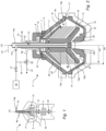
- Fig. 1 show a cross-section of an embodiment of a centrifugal separator 1 configured to separate a heavy phase and a light phase from a liquid feed mixture.
- the centrifugal separator 1 has a rotating part 4, comprising the centrifuge rotor 5 and drive spindle 4a.
- the centrifuge rotor 5 forms within itself a separation space 9a and a sludge space 9b, located radially outside the separation space 9a.
- a stack 10 of separation discs 10a is arranged coaxially around the axis of rotation (X) and axially below a top disc 11 and is thus arranged to rotate together with the centrifuge rotor 5.
- the separation discs 10a provide for an efficient separation of the liquid mixture into at least a liquid light phase and a liquid heavy phase.
- centrifugal separation of e.g. a liquid feed mixture to takes place during operation.
- the stack 10 is supported at its axially lowermost portion by distributor 13.
- the distributor 13 comprises an annular conical base portion 13a arranged to conduct liquid from the center of the centrifuge rotor 5 to a predetermined radial level in the separation space 9, and a central neck portion 13b extending upwards from the base portion 13a.
- the centrifugal separator 1 further comprises an inlet 14 in the form of a central inlet chamber formed within or under the distributor 13 into which a stationary inlet pipe 14a extends for supply of the liquid feed mixture to be separated.
- the inlet 14 communicates with the separation space 9 via passages 20 formed in the base portion 13a of the distributor 13.
- the passages may be arranged so that liquid mixture is transported to a radial level R1, which may correspond to the radial level of the outer portion of the stack of separation discs.
- the radial level R1 may be at the radial level of a plurality of cut-outs provided in the separation discs 10a.
- the top disc 11 and an upper inner wall part 28 of the centrifuge rotor 5 delimits at least one channel 25 extending from the radially inner portion of the sludge space 9b towards a central portion of the centrifuge rotor 5.
- the first liquid outlet 6 is arranged in a first outlet chamber 15, which is in fluid communication with the at least one channel 25 for discharge of a separated liquid heavy phase.
- the first liquid outlet 6 is in the form of a stationary paring disc arranged in the outlet chamber 15 for the separated heavy phase for discharging the heavy phase into outlet pipe 6a.
- the radially inner portion of the disc stack 10 communicates with a second outlet 7 for a separated light phase of the liquid feed mixture.
- the second outlet 7 is arranged in a second outlet chamber 8.
- the second outlet 7 is in the form of a stationary paring disc for discharge of the light phase into outlet pipe 7a.
- the paring disc 12 is supported in the second outlet chamber 8 by the stationary inlet pipe 14a
- the centrifuge rotor 5 is further provided with outlets 17 at the radially outer periphery of the sludge space 9b. These outlets 17 are evenly distributed around the rotor axis (X) and are arranged for intermittent discharge of a sludge component of the liquid feed mixture.
- the sludge component comprises denser particles forming a sludge phase.
- the opening of the outlets 17 is controlled by means of an operating slide 18 actuated by operating water in channel 19, as known in the art. In its position shown in the drawing, the operating slide 18 abuts sealingly at its periphery against the upper part 28 of the centrifuge rotor 5, thereby closing the sludge space 9b from connection with outlets 17, which are extending through the centrifuge rotor 5.
- the dimension of the recirculation inlet pipe may be selected based on the required recirculation flow rate.
- the conduit system 30 may be arranged for recirculating liquid heavy phase with a flow rate that is below 20 m/s in the recirculation inlet pipe 14a.
- the recirculation inlet 31a is connected with conduit 34 to the stationary outlet pipe 6a for the liquid heavy phase.
- This conduit also comprises regulating valve 35 for determining if liquid heavy phase released from the separator should be recirculated via conduit 34 to recirculation inlet 31a or released to drain via conduit 44.
- the regulating valve 35 may also be used to stop the discharge of separated liquid heavy phase completely.
- the recirculation inlet 31a is also connected to a source of liquid 42.
- This liquid may be displacement liquid that may be introduced to the centrifuge rotor 5 via the recirculation inlet before ejecting sludge via sludge outlets 17.
- Valve 41 may be used for controlling if displacement liquid should be introduced into the centrifuge rotor.
- the source of liquid 42 may for example be part of a water system onboard a ship.
- the liquid of higher density is instead forced out through the passages 25 over the top disc to the liquid outlet 6 for the heavy phase that is arranged at a radial distance that is larger than the radial level of the outlet 7 for the light phase.
- the throttling valve 33 is used to determine the flow of separated liquid heavy phase to the first outlet 6.
- the valve 35 at downstream of the first liquid outlet 6 may be closed until enough liquid heavy phase has been separated out from the liquid feed mixture. Opening of the valve 35 thus allows for discharge of the liquid heavy phase via the first liquid outlet 6.
- Discharged liquid heavy phase is recirculated via recirculation inlet pipe 31a and passages 32 arranged axially below the distributor back to the sludge space.
- recirculated heavy phase such as water is prevented from being mixed with the liquid feed mixture at the inlet, such as an oil.
- any water being discharged via the first liquid outlet 6 is recycled back to the sludge space 9b.
- recirculation is stopped, e.g. by guiding discharged water to drain via conduit 44, and displacement water is instead introduced via the conduit system 30 to force oil out of the centrifuge rotor to prevent loss of oil during subsequent intermittent discharge.
- the opening time of sludge outlets 17 is sufficiently long so that all separated solids and displacement water are thrown out of the centrifuge rotor, but sufficiently short to prevent loss of oil.
- a new separation period is started, and oil feed is again supplied to the separator 1.
Landscapes
- Centrifugal Separators (AREA)
Claims (15)
- Zentrifugalabscheider (1) zum Abscheiden einer flüssigen schweren Phase und einer flüssigen leichten Phase aus einem flüssigen Beschickungsgemisch, umfassend:ein Gestell (2), ein Antriebselement (3) und einen sich drehenden Teil (4),wobei das Antriebselement (3) konfiguriert ist, um den sich drehenden Teil (4) in Bezug auf das Gestell (2) um eine Drehachse (X) zu drehen, undwobei der sich drehende Teil (4) einen Zentrifugenrotor (5) umfasst, der einen Abscheidungsraum (9a) und einen Schlammraum (9b) umschließt;wobei der Abscheidungsraum (9) einen Stapel (10) von Abscheidungsscheiben (10a) umfasst, die koaxial um die Drehachse (X) angeordnet sind, und wobei der Schlammraum (9b) radial außerhalb des Stapels (10) von Abscheidungsscheiben (10a) angeordnet ist;wobei der Zentrifugalabscheider (1) ferner einen Einlass (14) zum Empfangen des flüssigen Beschickungsgemischs in den Zentrifugenrotor (5), einen ersten Auslass (6) für die abgeschiedene flüssige schwere Phase, einen zweiten Auslass (7) für die abgeschiedene flüssige leichte Phase und einen dritten Satz von Auslässen (17) zum Ausstoßen von Schlamm und flüssiger schwerer Phase, die sich im Abscheidungsraum (9b) ansammeln, umfasst;wobei der Zentrifugalabscheider (1) ferner ein Leitungssystem (30) zum Zurückführen von einer aus dem ersten Auslass zu dem Schlammraum (9b) innerhalb des Zentrifugenrotors (5) des Zentrifugalabscheiders ausgestoßenen abgeschiedenen flüssigen schweren Phase, ohne die zurückgeführte abgeschiedene flüssige schwere Phase mit dem flüssigen Beschickungsgemisch zu vermischen, umfasst.
- Zentrifugalabscheider (1) nach Anspruch 1, ferner umfassend ein Einlassrohr (14a), das zum Einführen des flüssigen Beschickungsgemischs in den Einlass (14) angeordnet ist, und wobei das Leitungssystem (30) ein innerhalb des Einlassrohrs (14a) angeordnetes Rückführungseinlassrohr (31) umfasst.
- Zentrifugalabscheider (1) nach einem der vorhergehenden Ansprüche, wobei der Abscheider ferner von dem ersten und zweiten Auslass verschiedene Schlammauslässe zum Ausstoßen von aus dem flüssigen Beschickungsgemisch abgeschiedenem Schlamm umfasst.
- Zentrifugalabscheider (1) nach einem der vorhergehenden Ansprüche, wobei der Stapel (10) von Abscheidungsscheiben (10a) axial auf einem Verteiler (13) angeordnet ist, und wobei das Leitungssystem (30) mindestens einen Kanal (32) umfasst, der axial unterhalb des Verteilers (13) angeordnet ist, um die zurückgeführte flüssige schwere Phase radial nach außen zu dem Schlammraum (9b) zu leiten.
- Zentrifugalabscheider nach Anspruch 4 und 2, wobei sich das Rückführungseinlassrohr (31) zu dem mindestens einen axial unterhalb des Verteilers (13) angeordneten Kanal (32) erstreckt.
- Zentrifugalabscheider (1) nach einem der vorhergehenden Ansprüche, wobei der Zentrifugalabscheider (1) ferner ein Drosselventil (33) umfasst, das zum Drosseln der abgeschiedenen flüssigen schweren Phase angeordnet ist, wobei das Drosselventil (33) stromaufwärts des ersten Auslasses für die schwere Phase angeordnet ist.
- Zentrifugalabscheider nach einem der vorhergehenden Ansprüche, wobei das Leitungssystem (30) ferner einen Rückführungseinlass und eine Leitung umfasst, die den ersten Auslass (6) für die flüssige schwere Phase mit dem Rückführungseinlass verbindet.
- Zentrifugalabscheider nach Anspruch 7, wobei die Leitung, die den ersten Auslass (6) für die flüssige schwere Phase mit dem Rückführungseinlass verbindet, ein Ventilmittel umfasst, das zum Bestimmen der Menge der abgeschiedenen flüssigen schweren Phase, die zu dem Rückführungseinlass zurückgeführt wird, angeordnet ist.
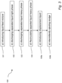
- Verfahren (100) zum Abscheiden einer flüssigen schweren Phase und einer flüssigen leichten Phase aus einem flüssigen Beschickungsgemisch, umfassend die folgenden Schritte:a) Einführen (101) des flüssigen Beschickungsgemischs in einen Zentrifugalabscheider (1) nach einem der Ansprüche 1 bis 8;b) Ausstoßen (102) einer abgeschiedenen flüssigen leichten Phase aus dem Zentrifugalabscheider (1),c) Ausstoßen (103) einer abgeschiedenen flüssigen schweren Phase aus dem Zentrifugalabscheider (1),
undd) Zurückführen (104) mindestens eines Abschnitts der ausgestoßenen abgeschiedenen flüssigen schweren Phase in den Schlammraum (9b), ohne die zurückgeführte abgeschiedene flüssige schwere Phase mit dem flüssigen Beschickungsgemisch zu mischen. - Verfahren nach Anspruch 9, wobei der Zentrifugalabscheider (1) ein Einlassrohr (14a) umfasst, das zum Einführen des flüssigen Beschickungsgemischs in den Einlass (14) angeordnet ist, und wobei die Rückführung über ein innerhalb des Einlassrohrs (14a) angeordnetes Rückführungseinlassrohr (31) durchgeführt wird.
- Verfahren nach einem der Ansprüche 9 oder 10, wobei der Stapel (10) von Abscheidungsscheiben (10a) axial auf einem Verteiler (13) angeordnet ist, und wobei die Rückführung das Leiten der zurückgeführten flüssigen schweren Phase radial nach außen unter den Verteiler (13) umfasst.
- Verfahren nach Anspruch 11, wobei Schritt d) das Leiten der abgeschiedenen flüssigen schweren Phase in den Schlammraum (9b) an einer radialen Position umfasst, die sich an der radial äußeren Kante des Verteilers (13) befindet.
- Verfahren nach einem der Ansprüche 9 bis 12, das ferner einen Schritt e) bestehend aus Folgendem umfasst:
intermittierendes Ausstoßens (105b) einer abgeschiedenen festen Phase durch einen Satz radialer Auslässe (17) umfasst, die am äußeren Umfang des Zentrifugenrotors (5) angeordnet sind. - Verfahren nach Anspruch 13 und 9, wobei Schritt e) ferner das Einleiten von Verdrängungsflüssigkeit (105a) über das Leitungssystem (30) in den Zentrifugenrotor zum Zurückführen der abgeschiedenen flüssigen schweren Phase vor dem Auswerfen der abgeschiedenen festen Phase umfasst.
- Verfahren nach einem der Ansprüche 9 bis 14, wobei das flüssige Beschickungsgemisch ein öliges Gemisch ist und die flüssige schwere Phase eine wässrige Phase, wie z. B. Wasser, ist.
Priority Applications (6)
| Application Number | Priority Date | Filing Date | Title |
|---|---|---|---|
| EP20212159.6A EP4008437B1 (de) | 2020-12-07 | 2020-12-07 | Verfahren zum betrieb eines zentrifugalabscheiders |
| KR1020237022591A KR20230111259A (ko) | 2020-12-07 | 2021-11-17 | 원심 분리기 및 원심 분리기의 동작 방법 |
| PCT/EP2021/081957 WO2022122326A1 (en) | 2020-12-07 | 2021-11-17 | A centrifugal separator and a method of operating a centrifugal separator |
| CN202180081896.9A CN116583356B (zh) | 2020-12-07 | 2021-11-17 | 离心分离器和操作离心分离器的方法 |
| JP2023534399A JP7532664B2 (ja) | 2020-12-07 | 2021-11-17 | 遠心分離機及び遠心分離機を動作させる方法 |
| US18/037,177 US20240017273A1 (en) | 2020-12-07 | 2021-11-17 | A centrifugal separator and a method of operating a centrifugal separator |
Applications Claiming Priority (1)
| Application Number | Priority Date | Filing Date | Title |
|---|---|---|---|
| EP20212159.6A EP4008437B1 (de) | 2020-12-07 | 2020-12-07 | Verfahren zum betrieb eines zentrifugalabscheiders |
Publications (2)
| Publication Number | Publication Date |
|---|---|
| EP4008437A1 EP4008437A1 (de) | 2022-06-08 |
| EP4008437B1 true EP4008437B1 (de) | 2025-04-09 |
Family
ID=73740250
Family Applications (1)
| Application Number | Title | Priority Date | Filing Date |
|---|---|---|---|
| EP20212159.6A Active EP4008437B1 (de) | 2020-12-07 | 2020-12-07 | Verfahren zum betrieb eines zentrifugalabscheiders |
Country Status (6)
| Country | Link |
|---|---|
| US (1) | US20240017273A1 (de) |
| EP (1) | EP4008437B1 (de) |
| JP (1) | JP7532664B2 (de) |
| KR (1) | KR20230111259A (de) |
| CN (1) | CN116583356B (de) |
| WO (1) | WO2022122326A1 (de) |
Families Citing this family (1)
| Publication number | Priority date | Publication date | Assignee | Title |
|---|---|---|---|---|
| US10654050B1 (en) | 2019-05-21 | 2020-05-19 | Empirical Innovations, Inc. | Centrifugal separators and separation methods employing multiple pistons and facilitating intermediate material ejection |
Citations (6)
| Publication number | Priority date | Publication date | Assignee | Title |
|---|---|---|---|---|
| DE874427C (de) | 1940-11-22 | 1953-04-23 | Werkspoor Nv | Verfahren und Schleudermaschine zum Trennen von zwei fluessigen Phasen durch Schleuderwirkung im Dauerbetrieb |
| DE1018796B (de) | 1955-01-24 | 1957-10-31 | Westfalia Separator Ag | Duesenzentrifuge zum Klaeren und Trennen von zwei fluessigen Komponenten mit Konzentratrueckfuehrung oder Waschfluessigkeitzufuehrung in die Trommel |
| US3640452A (en) | 1968-10-14 | 1972-02-08 | Alfa Laval Ab | Centrifugal separator |
| EP0205246A1 (de) | 1985-06-07 | 1986-12-17 | Alfa-Laval Separation Ab | Zentrifugal-Separator |
| DE3601814A1 (de) | 1986-01-22 | 1987-07-23 | Westfalia Separator Ag | Verfahren und vorrichtung zum trennen von zwei fluessigen phasen mittels einer zentrifuge |
| EP0241128A1 (de) | 1986-03-12 | 1987-10-14 | Alfa-Laval Separation Ab | Zentrifugalseparator mit Rückzirkulation von separiertem Schlamm |
Family Cites Families (7)
| Publication number | Priority date | Publication date | Assignee | Title |
|---|---|---|---|---|
| SE452260B (sv) * | 1986-03-12 | 1987-11-23 | Alfa Laval Separation Ab | Centrifugalseparator anordnad for utmatning av en separerad produkt med bestemd koncentration |
| DE3802305C1 (en) * | 1988-01-27 | 1989-10-05 | Westfalia Separator Ag, 4740 Oelde, De | Process and apparatus for the centrifugal removal of bacteria from milk |
| SE461019B (sv) * | 1988-05-02 | 1989-12-18 | Alfa Laval Marine Power Eng | Centrifugalseparator med ett pumporgan, inraettat foer att aastadkomma en cirkulation av vaetska i en stroemningskrets |
| FI119802B (fi) * | 2007-07-13 | 2009-03-31 | Waertsilae Finland Oy | Menetelmä separaattorin käyttämiseksi ja separaattori |
| SE535959C2 (sv) * | 2010-01-29 | 2013-03-05 | Alfa Laval Corp Ab | System innefattande centrifugalseparator samt metod för kontroll av detsamma |
| EP2799146B1 (de) * | 2013-05-02 | 2019-11-06 | Alfa Laval Corporate AB | Ausstoß von Feststoffteilchen aus einem Fliehkraftabscheider |
| EP3207995B1 (de) * | 2016-02-22 | 2020-07-01 | Alfa Laval Corporate AB | Zentrifugalabscheider mit einem intermittierenden entladungssystem |
-
2020
- 2020-12-07 EP EP20212159.6A patent/EP4008437B1/de active Active
-
2021
- 2021-11-17 JP JP2023534399A patent/JP7532664B2/ja active Active
- 2021-11-17 US US18/037,177 patent/US20240017273A1/en active Pending
- 2021-11-17 KR KR1020237022591A patent/KR20230111259A/ko active Pending
- 2021-11-17 CN CN202180081896.9A patent/CN116583356B/zh active Active
- 2021-11-17 WO PCT/EP2021/081957 patent/WO2022122326A1/en not_active Ceased
Patent Citations (6)
| Publication number | Priority date | Publication date | Assignee | Title |
|---|---|---|---|---|
| DE874427C (de) | 1940-11-22 | 1953-04-23 | Werkspoor Nv | Verfahren und Schleudermaschine zum Trennen von zwei fluessigen Phasen durch Schleuderwirkung im Dauerbetrieb |
| DE1018796B (de) | 1955-01-24 | 1957-10-31 | Westfalia Separator Ag | Duesenzentrifuge zum Klaeren und Trennen von zwei fluessigen Komponenten mit Konzentratrueckfuehrung oder Waschfluessigkeitzufuehrung in die Trommel |
| US3640452A (en) | 1968-10-14 | 1972-02-08 | Alfa Laval Ab | Centrifugal separator |
| EP0205246A1 (de) | 1985-06-07 | 1986-12-17 | Alfa-Laval Separation Ab | Zentrifugal-Separator |
| DE3601814A1 (de) | 1986-01-22 | 1987-07-23 | Westfalia Separator Ag | Verfahren und vorrichtung zum trennen von zwei fluessigen phasen mittels einer zentrifuge |
| EP0241128A1 (de) | 1986-03-12 | 1987-10-14 | Alfa-Laval Separation Ab | Zentrifugalseparator mit Rückzirkulation von separiertem Schlamm |
Non-Patent Citations (1)
| Title |
|---|
| "Fest-Flüssig-Trennung - Industrie-Zentrifugen, Band II, Maschinen- & Verfahrenstechnik", 1 January 2004, DRM PRESS, Männedorf, ISBN: 3-9522794-0-4, article WERNER H. STAHL: "Kapitel 6: Separatoren", pages: 725 - 838, XP009564428 |
Also Published As
| Publication number | Publication date |
|---|---|
| US20240017273A1 (en) | 2024-01-18 |
| JP2023551992A (ja) | 2023-12-13 |
| EP4008437A1 (de) | 2022-06-08 |
| WO2022122326A1 (en) | 2022-06-16 |
| JP7532664B2 (ja) | 2024-08-13 |
| CN116583356B (zh) | 2026-02-24 |
| CN116583356A (zh) | 2023-08-11 |
| KR20230111259A (ko) | 2023-07-25 |
Similar Documents
| Publication | Publication Date | Title |
|---|---|---|
| US10940489B2 (en) | Centrifugal separator with disc stack having discs of different diameters | |
| EP2155399B1 (de) | Verfahren und vorrichtung zur reinigung eines fluids in einem zentrifugalabscheider | |
| EP2883947B1 (de) | Kontinuierliche Reinigung von Motorölen mit einem Dreiphasenabscheider | |
| JPH07507716A (ja) | 遠心力により流体混合体をその成分に分離する装置及び方法 | |
| EP0390899A1 (de) | Zentrifugalabscheider. | |
| CN103153474B (zh) | 用于借助离心分离机对产品进行相分离的方法 | |
| US5941811A (en) | Centrifugal separator to free a liquid from both lighter particles and heavier particles | |
| EP4008437B1 (de) | Verfahren zum betrieb eines zentrifugalabscheiders | |
| US4816152A (en) | Separator for separating a mixture of two liquids having different specific weights | |
| SE500414C2 (sv) | Centrifugalseparator med stationärt utmatningsorgan | |
| JP7575599B2 (ja) | ディスクスタックを備える遠心分離機 | |
| EP4046719B1 (de) | Zentrifugalabscheider | |
| EP1075331B1 (de) | Verfahren und gerät zum reinigen einer trennzentrifuge | |
| US5897484A (en) | Centrifugal separator to free a liquid from bath lighter particles and heavier particles | |
| JP2856275B2 (ja) | 遠心分離機の洗浄装置 | |
| US20240390917A1 (en) | A centrifugal separator | |
| EP0879090A1 (de) | Abscheider zum abscheiden von zwei flüssigkeiten |
Legal Events
| Date | Code | Title | Description |
|---|---|---|---|
| PUAI | Public reference made under article 153(3) epc to a published international application that has entered the european phase |
Free format text: ORIGINAL CODE: 0009012 |
|
| STAA | Information on the status of an ep patent application or granted ep patent |
Free format text: STATUS: THE APPLICATION HAS BEEN PUBLISHED |
|
| AK | Designated contracting states |
Kind code of ref document: A1 Designated state(s): AL AT BE BG CH CY CZ DE DK EE ES FI FR GB GR HR HU IE IS IT LI LT LU LV MC MK MT NL NO PL PT RO RS SE SI SK SM TR |
|
| STAA | Information on the status of an ep patent application or granted ep patent |
Free format text: STATUS: REQUEST FOR EXAMINATION WAS MADE |
|
| 17P | Request for examination filed |
Effective date: 20221110 |
|
| RBV | Designated contracting states (corrected) |
Designated state(s): AL AT BE BG CH CY CZ DE DK EE ES FI FR GB GR HR HU IE IS IT LI LT LU LV MC MK MT NL NO PL PT RO RS SE SI SK SM TR |
|
| GRAP | Despatch of communication of intention to grant a patent |
Free format text: ORIGINAL CODE: EPIDOSNIGR1 |
|
| STAA | Information on the status of an ep patent application or granted ep patent |
Free format text: STATUS: GRANT OF PATENT IS INTENDED |
|
| INTG | Intention to grant announced |
Effective date: 20241220 |
|
| P01 | Opt-out of the competence of the unified patent court (upc) registered |
Free format text: CASE NUMBER: APP_2487/2025 Effective date: 20250115 |
|
| GRAS | Grant fee paid |
Free format text: ORIGINAL CODE: EPIDOSNIGR3 |
|
| GRAA | (expected) grant |
Free format text: ORIGINAL CODE: 0009210 |
|
| STAA | Information on the status of an ep patent application or granted ep patent |
Free format text: STATUS: THE PATENT HAS BEEN GRANTED |
|
| AK | Designated contracting states |
Kind code of ref document: B1 Designated state(s): AL AT BE BG CH CY CZ DE DK EE ES FI FR GB GR HR HU IE IS IT LI LT LU LV MC MK MT NL NO PL PT RO RS SE SI SK SM TR |
|
| REG | Reference to a national code |
Ref country code: GB Ref legal event code: FG4D |
|
| RIN1 | Information on inventor provided before grant (corrected) |
Inventor name: PITKAEMAEKI, JOUKO |
|
| REG | Reference to a national code |
Ref country code: CH Ref legal event code: EP |
|
| REG | Reference to a national code |
Ref country code: DE Ref legal event code: R096 Ref document number: 602020049024 Country of ref document: DE |
|
| REG | Reference to a national code |
Ref country code: IE Ref legal event code: FG4D |
|
| REG | Reference to a national code |
Ref country code: NL Ref legal event code: MP Effective date: 20250409 |
|
| PG25 | Lapsed in a contracting state [announced via postgrant information from national office to epo] |
Ref country code: NL Free format text: LAPSE BECAUSE OF FAILURE TO SUBMIT A TRANSLATION OF THE DESCRIPTION OR TO PAY THE FEE WITHIN THE PRESCRIBED TIME-LIMIT Effective date: 20250409 |
|
| REG | Reference to a national code |
Ref country code: AT Ref legal event code: MK05 Ref document number: 1783089 Country of ref document: AT Kind code of ref document: T Effective date: 20250409 |
|
| PG25 | Lapsed in a contracting state [announced via postgrant information from national office to epo] |
Ref country code: FI Free format text: LAPSE BECAUSE OF FAILURE TO SUBMIT A TRANSLATION OF THE DESCRIPTION OR TO PAY THE FEE WITHIN THE PRESCRIBED TIME-LIMIT Effective date: 20250409 Ref country code: PT Free format text: LAPSE BECAUSE OF FAILURE TO SUBMIT A TRANSLATION OF THE DESCRIPTION OR TO PAY THE FEE WITHIN THE PRESCRIBED TIME-LIMIT Effective date: 20250811 Ref country code: ES Free format text: LAPSE BECAUSE OF FAILURE TO SUBMIT A TRANSLATION OF THE DESCRIPTION OR TO PAY THE FEE WITHIN THE PRESCRIBED TIME-LIMIT Effective date: 20250409 |
|
| REG | Reference to a national code |
Ref country code: LT Ref legal event code: MG9D |
|
| PG25 | Lapsed in a contracting state [announced via postgrant information from national office to epo] |
Ref country code: GR Free format text: LAPSE BECAUSE OF FAILURE TO SUBMIT A TRANSLATION OF THE DESCRIPTION OR TO PAY THE FEE WITHIN THE PRESCRIBED TIME-LIMIT Effective date: 20250710 Ref country code: NO Free format text: LAPSE BECAUSE OF FAILURE TO SUBMIT A TRANSLATION OF THE DESCRIPTION OR TO PAY THE FEE WITHIN THE PRESCRIBED TIME-LIMIT Effective date: 20250709 |
|
| PG25 | Lapsed in a contracting state [announced via postgrant information from national office to epo] |
Ref country code: PL Free format text: LAPSE BECAUSE OF FAILURE TO SUBMIT A TRANSLATION OF THE DESCRIPTION OR TO PAY THE FEE WITHIN THE PRESCRIBED TIME-LIMIT Effective date: 20250409 |
|
| PG25 | Lapsed in a contracting state [announced via postgrant information from national office to epo] |
Ref country code: BG Free format text: LAPSE BECAUSE OF FAILURE TO SUBMIT A TRANSLATION OF THE DESCRIPTION OR TO PAY THE FEE WITHIN THE PRESCRIBED TIME-LIMIT Effective date: 20250409 |
|
| PG25 | Lapsed in a contracting state [announced via postgrant information from national office to epo] |
Ref country code: HR Free format text: LAPSE BECAUSE OF FAILURE TO SUBMIT A TRANSLATION OF THE DESCRIPTION OR TO PAY THE FEE WITHIN THE PRESCRIBED TIME-LIMIT Effective date: 20250409 |
|
| PG25 | Lapsed in a contracting state [announced via postgrant information from national office to epo] |
Ref country code: AT Free format text: LAPSE BECAUSE OF FAILURE TO SUBMIT A TRANSLATION OF THE DESCRIPTION OR TO PAY THE FEE WITHIN THE PRESCRIBED TIME-LIMIT Effective date: 20250409 |
|
| PGFP | Annual fee paid to national office [announced via postgrant information from national office to epo] |
Ref country code: FR Payment date: 20250930 Year of fee payment: 6 |
|
| PG25 | Lapsed in a contracting state [announced via postgrant information from national office to epo] |
Ref country code: RS Free format text: LAPSE BECAUSE OF FAILURE TO SUBMIT A TRANSLATION OF THE DESCRIPTION OR TO PAY THE FEE WITHIN THE PRESCRIBED TIME-LIMIT Effective date: 20250709 |
|
| PG25 | Lapsed in a contracting state [announced via postgrant information from national office to epo] |
Ref country code: IS Free format text: LAPSE BECAUSE OF FAILURE TO SUBMIT A TRANSLATION OF THE DESCRIPTION OR TO PAY THE FEE WITHIN THE PRESCRIBED TIME-LIMIT Effective date: 20250809 |
|
| PG25 | Lapsed in a contracting state [announced via postgrant information from national office to epo] |
Ref country code: LV Free format text: LAPSE BECAUSE OF FAILURE TO SUBMIT A TRANSLATION OF THE DESCRIPTION OR TO PAY THE FEE WITHIN THE PRESCRIBED TIME-LIMIT Effective date: 20250409 |
|
| PGFP | Annual fee paid to national office [announced via postgrant information from national office to epo] |
Ref country code: DE Payment date: 20250930 Year of fee payment: 6 |
|
| REG | Reference to a national code |
Ref country code: DE Ref legal event code: R026 Ref document number: 602020049024 Country of ref document: DE |
|
| PG25 | Lapsed in a contracting state [announced via postgrant information from national office to epo] |
Ref country code: SM Free format text: LAPSE BECAUSE OF FAILURE TO SUBMIT A TRANSLATION OF THE DESCRIPTION OR TO PAY THE FEE WITHIN THE PRESCRIBED TIME-LIMIT Effective date: 20250409 Ref country code: DK Free format text: LAPSE BECAUSE OF FAILURE TO SUBMIT A TRANSLATION OF THE DESCRIPTION OR TO PAY THE FEE WITHIN THE PRESCRIBED TIME-LIMIT Effective date: 20250409 |
|
| PGFP | Annual fee paid to national office [announced via postgrant information from national office to epo] |
Ref country code: IT Payment date: 20251121 Year of fee payment: 6 |
|
| PGFP | Annual fee paid to national office [announced via postgrant information from national office to epo] |
Ref country code: BE Payment date: 20251003 Year of fee payment: 6 |
|
| PLBI | Opposition filed |
Free format text: ORIGINAL CODE: 0009260 |
|
| PG25 | Lapsed in a contracting state [announced via postgrant information from national office to epo] |
Ref country code: CZ Free format text: LAPSE BECAUSE OF FAILURE TO SUBMIT A TRANSLATION OF THE DESCRIPTION OR TO PAY THE FEE WITHIN THE PRESCRIBED TIME-LIMIT Effective date: 20250409 |
|
| REG | Reference to a national code |
Ref country code: CH Ref legal event code: L10 Free format text: ST27 STATUS EVENT CODE: U-0-0-L10-L00 (AS PROVIDED BY THE NATIONAL OFFICE) Effective date: 20260121 |
|
| PLAX | Notice of opposition and request to file observation + time limit sent |
Free format text: ORIGINAL CODE: EPIDOSNOBS2 |
|
| PG25 | Lapsed in a contracting state [announced via postgrant information from national office to epo] |
Ref country code: EE Free format text: LAPSE BECAUSE OF FAILURE TO SUBMIT A TRANSLATION OF THE DESCRIPTION OR TO PAY THE FEE WITHIN THE PRESCRIBED TIME-LIMIT Effective date: 20250409 |
|
| PG25 | Lapsed in a contracting state [announced via postgrant information from national office to epo] |
Ref country code: SK Free format text: LAPSE BECAUSE OF FAILURE TO SUBMIT A TRANSLATION OF THE DESCRIPTION OR TO PAY THE FEE WITHIN THE PRESCRIBED TIME-LIMIT Effective date: 20250409 Ref country code: RO Free format text: LAPSE BECAUSE OF FAILURE TO SUBMIT A TRANSLATION OF THE DESCRIPTION OR TO PAY THE FEE WITHIN THE PRESCRIBED TIME-LIMIT Effective date: 20250409 |
|
| PLAB | Opposition data, opponent's data or that of the opponent's representative modified |
Free format text: ORIGINAL CODE: 0009299OPPO |
|
| REG | Reference to a national code |
Ref country code: CH Ref legal event code: L10 Free format text: ST27 STATUS EVENT CODE: U-0-0-L10-L00 (AS PROVIDED BY THE NATIONAL OFFICE) Effective date: 20260204 |
|
| 26 | Opposition filed |
Opponent name: GEA WESTFALIA SEPARATOR GROUP GMBH Effective date: 20260108 |
|
| R26 | Opposition filed (corrected) |
Opponent name: GEA WESTFALIA SEPARATOR GROUP GMBH Effective date: 20260108 |