EP4008442B1 - Abgabeeinrichtung und spender - Google Patents
Abgabeeinrichtung und spender Download PDFInfo
- Publication number
- EP4008442B1 EP4008442B1 EP20211840.2A EP20211840A EP4008442B1 EP 4008442 B1 EP4008442 B1 EP 4008442B1 EP 20211840 A EP20211840 A EP 20211840A EP 4008442 B1 EP4008442 B1 EP 4008442B1
- Authority
- EP
- European Patent Office
- Prior art keywords
- actuating lever
- dispensing device
- actuating
- locking
- dispensing
- Prior art date
- Legal status (The legal status is an assumption and is not a legal conclusion. Google has not performed a legal analysis and makes no representation as to the accuracy of the status listed.)
- Active
Links
Images


Classifications
-
- B—PERFORMING OPERATIONS; TRANSPORTING
- B05—SPRAYING OR ATOMISING IN GENERAL; APPLYING FLUENT MATERIALS TO SURFACES, IN GENERAL
- B05B—SPRAYING APPARATUS; ATOMISING APPARATUS; NOZZLES
- B05B11/00—Single-unit hand-held apparatus in which flow of contents is produced by the muscular force of the operator at the moment of use
- B05B11/0005—Components or details
- B05B11/0037—Containers
- B05B11/0039—Containers associated with means for compensating the pressure difference between the ambient pressure and the pressure inside the container, e.g. pressure relief means
- B05B11/0044—Containers associated with means for compensating the pressure difference between the ambient pressure and the pressure inside the container, e.g. pressure relief means compensating underpressure by ingress of atmospheric air into the container, i.e. with venting means
-
- B—PERFORMING OPERATIONS; TRANSPORTING
- B05—SPRAYING OR ATOMISING IN GENERAL; APPLYING FLUENT MATERIALS TO SURFACES, IN GENERAL
- B05B—SPRAYING APPARATUS; ATOMISING APPARATUS; NOZZLES
- B05B11/00—Single-unit hand-held apparatus in which flow of contents is produced by the muscular force of the operator at the moment of use
- B05B11/01—Single-unit hand-held apparatus in which flow of contents is produced by the muscular force of the operator at the moment of use characterised by the means producing the flow
- B05B11/10—Pump arrangements for transferring the contents from the container to a pump chamber by a sucking effect and forcing the contents out through the dispensing nozzle
- B05B11/1028—Pumps having a pumping chamber with a deformable wall
- B05B11/1029—Pumps having a pumping chamber with a deformable wall actuated by a lever
- B05B11/103—Pumps having a pumping chamber with a deformable wall actuated by a lever without substantial movement of the nozzle in the direction of the pressure stroke
-
- B—PERFORMING OPERATIONS; TRANSPORTING
- B05—SPRAYING OR ATOMISING IN GENERAL; APPLYING FLUENT MATERIALS TO SURFACES, IN GENERAL
- B05B—SPRAYING APPARATUS; ATOMISING APPARATUS; NOZZLES
- B05B11/00—Single-unit hand-held apparatus in which flow of contents is produced by the muscular force of the operator at the moment of use
- B05B11/01—Single-unit hand-held apparatus in which flow of contents is produced by the muscular force of the operator at the moment of use characterised by the means producing the flow
- B05B11/10—Pump arrangements for transferring the contents from the container to a pump chamber by a sucking effect and forcing the contents out through the dispensing nozzle
- B05B11/1028—Pumps having a pumping chamber with a deformable wall
- B05B11/1033—Pumps having a pumping chamber with a deformable wall the deformable wall, the inlet and outlet valve elements being integrally formed, e.g. moulded
-
- B—PERFORMING OPERATIONS; TRANSPORTING
- B05—SPRAYING OR ATOMISING IN GENERAL; APPLYING FLUENT MATERIALS TO SURFACES, IN GENERAL
- B05B—SPRAYING APPARATUS; ATOMISING APPARATUS; NOZZLES
- B05B11/00—Single-unit hand-held apparatus in which flow of contents is produced by the muscular force of the operator at the moment of use
- B05B11/01—Single-unit hand-held apparatus in which flow of contents is produced by the muscular force of the operator at the moment of use characterised by the means producing the flow
- B05B11/10—Pump arrangements for transferring the contents from the container to a pump chamber by a sucking effect and forcing the contents out through the dispensing nozzle
- B05B11/1028—Pumps having a pumping chamber with a deformable wall
- B05B11/1035—Pumps having a pumping chamber with a deformable wall the pumping chamber being a bellow
-
- B—PERFORMING OPERATIONS; TRANSPORTING
- B05—SPRAYING OR ATOMISING IN GENERAL; APPLYING FLUENT MATERIALS TO SURFACES, IN GENERAL
- B05B—SPRAYING APPARATUS; ATOMISING APPARATUS; NOZZLES
- B05B11/00—Single-unit hand-held apparatus in which flow of contents is produced by the muscular force of the operator at the moment of use
- B05B11/01—Single-unit hand-held apparatus in which flow of contents is produced by the muscular force of the operator at the moment of use characterised by the means producing the flow
- B05B11/10—Pump arrangements for transferring the contents from the container to a pump chamber by a sucking effect and forcing the contents out through the dispensing nozzle
- B05B11/1042—Components or details
- B05B11/1052—Actuation means
- B05B11/1056—Actuation means comprising rotatable or articulated levers
- B05B11/1057—Triggers, i.e. actuation means consisting of a single lever having one end rotating or pivoting around an axis or a hinge fixedly attached to the container, and another end directly actuated by the user
-
- B—PERFORMING OPERATIONS; TRANSPORTING
- B05—SPRAYING OR ATOMISING IN GENERAL; APPLYING FLUENT MATERIALS TO SURFACES, IN GENERAL
- B05B—SPRAYING APPARATUS; ATOMISING APPARATUS; NOZZLES
- B05B11/00—Single-unit hand-held apparatus in which flow of contents is produced by the muscular force of the operator at the moment of use
- B05B11/01—Single-unit hand-held apparatus in which flow of contents is produced by the muscular force of the operator at the moment of use characterised by the means producing the flow
- B05B11/10—Pump arrangements for transferring the contents from the container to a pump chamber by a sucking effect and forcing the contents out through the dispensing nozzle
- B05B11/1042—Components or details
- B05B11/1059—Means for locking a pump or its actuation means in a fixed position
-
- B—PERFORMING OPERATIONS; TRANSPORTING
- B05—SPRAYING OR ATOMISING IN GENERAL; APPLYING FLUENT MATERIALS TO SURFACES, IN GENERAL
- B05B—SPRAYING APPARATUS; ATOMISING APPARATUS; NOZZLES
- B05B11/00—Single-unit hand-held apparatus in which flow of contents is produced by the muscular force of the operator at the moment of use
- B05B11/01—Single-unit hand-held apparatus in which flow of contents is produced by the muscular force of the operator at the moment of use characterised by the means producing the flow
- B05B11/10—Pump arrangements for transferring the contents from the container to a pump chamber by a sucking effect and forcing the contents out through the dispensing nozzle
- B05B11/1042—Components or details
- B05B11/1066—Pump inlet valves
- B05B11/1067—Pump inlet valves actuated by pressure
- B05B11/1069—Pump inlet valves actuated by pressure the valve being made of a resiliently deformable material or being urged in a closed position by a spring
-
- B—PERFORMING OPERATIONS; TRANSPORTING
- B05—SPRAYING OR ATOMISING IN GENERAL; APPLYING FLUENT MATERIALS TO SURFACES, IN GENERAL
- B05B—SPRAYING APPARATUS; ATOMISING APPARATUS; NOZZLES
- B05B11/00—Single-unit hand-held apparatus in which flow of contents is produced by the muscular force of the operator at the moment of use
- B05B11/01—Single-unit hand-held apparatus in which flow of contents is produced by the muscular force of the operator at the moment of use characterised by the means producing the flow
- B05B11/10—Pump arrangements for transferring the contents from the container to a pump chamber by a sucking effect and forcing the contents out through the dispensing nozzle
- B05B11/1095—Pump arrangements for transferring the contents from the container to a pump chamber by a sucking effect and forcing the contents out through the dispensing nozzle with movable suction side
-
- B—PERFORMING OPERATIONS; TRANSPORTING
- B05—SPRAYING OR ATOMISING IN GENERAL; APPLYING FLUENT MATERIALS TO SURFACES, IN GENERAL
- B05B—SPRAYING APPARATUS; ATOMISING APPARATUS; NOZZLES
- B05B1/00—Nozzles, spray heads or other outlets, with or without auxiliary devices such as valves, heating means
- B05B1/12—Nozzles, spray heads or other outlets, with or without auxiliary devices such as valves, heating means capable of producing different kinds of discharge, e.g. either jet or spray
-
- B—PERFORMING OPERATIONS; TRANSPORTING
- B05—SPRAYING OR ATOMISING IN GENERAL; APPLYING FLUENT MATERIALS TO SURFACES, IN GENERAL
- B05B—SPRAYING APPARATUS; ATOMISING APPARATUS; NOZZLES
- B05B11/00—Single-unit hand-held apparatus in which flow of contents is produced by the muscular force of the operator at the moment of use
- B05B11/0005—Components or details
- B05B11/0008—Sealing or attachment arrangements between sprayer and container
-
- B—PERFORMING OPERATIONS; TRANSPORTING
- B05—SPRAYING OR ATOMISING IN GENERAL; APPLYING FLUENT MATERIALS TO SURFACES, IN GENERAL
- B05B—SPRAYING APPARATUS; ATOMISING APPARATUS; NOZZLES
- B05B11/00—Single-unit hand-held apparatus in which flow of contents is produced by the muscular force of the operator at the moment of use
- B05B11/0005—Components or details
- B05B11/0027—Means for neutralising the actuation of the sprayer ; Means for preventing access to the sprayer actuation means
- B05B11/0029—Valves not actuated by pressure
Definitions
- the present invention relates to a dispensing device for dispensing a fluid according to the preamble of claim 1 and a dispenser for dispensing a fluid according to the preamble of claim 11.
- the present invention relates to a dispenser for storing and dispensing cleaning agents or pharmaceutical or cosmetic fluids, in particular liquids.
- a container of the dispenser can hold a fluid that can be conveyed out of the container by means of a dispensing device attached to the container and dispensed by means of the dispensing device.
- the fluid can be dispensed in various forms, for example as a spray or aerosol or as a foam.
- the WO 2019/175349 A1 relates to a dispensing device for dispensing a fluid, which has a pumping device for conveying the fluid from a container.
- the pumping device has a bellows for pumping and can be operated by means of a manually operated actuating lever.
- the actuating lever can be secured against unwanted actuation.
- an actuating arm of the actuating lever is folded up in a secured position, in particular secured to a dispensing head of the dispensing device.
- the actuating lever has a locking element that can be pivoted relative to the actuating arm, which can be arranged between the actuating arm and a housing of the dispensing device and thus blocks pivoting of the actuating lever.
- the EP 0 177 898 A1 relates to a spray bottle with an operating lever.
- a rod-shaped element is pivotably mounted on the housing of the head of the spray bottle via a film hinge.
- the rod-shaped element can engage in a section of the lever so that pivoting of the lever is blocked.
- the EP 3 552 989 A1 relates to an adapter for product dispensers and a product dispenser.
- the adapter comprises a pivotable actuating lever with a handle, wherein the actuating lever can be moved from an unlocking position, in which the handle can be actuated to open a valve, to a locking position in which actuation of the handle is blocked.
- the US 2005/0184093 A1 relates to a lockable dispensing head.
- the dispensing head has two parts, an upper part having a push button for actuating a valve and being rotatable relative to the lower part. In a first rotational position, the dispensing head can dispense a product, while this is not possible in a second rotational position.
- the US 2013/0277397 A1 relates to an aerosol dispenser with an actuating lever.
- the aerosol dispenser may have a lock to prevent the lever from actuating an aerosol valve, wherein a dispensing head of the dispenser is rotatable relative to a base into a locked and an unlocked rotational position.
- a dispensing device is designed to dispense a fluid, in particular held in an associated container and/or connected to the dispensing device.
- the dispensing device has a conveying device for conveying the fluid.
- the conveying device is preferably designed as a pump or has one.
- the conveying device or pumping device particularly preferably has a flexible bellows for conveying the fluid.
- the fluid can be conveyed into the bellows by an expansion of the bellows or a negative pressure created by the expansion and can be discharged from the bellows by a compression of the bellows.
- the pumping device can have a pump piston or the like as a conveying element instead of a bellows.
- the conveying device can also be implemented without a pump or pumping device, for example in a pressurized container.
- the dispensing device has a manually operable actuating lever for actuating the conveyor device or dispensing device.
- the actuating lever is preferably arranged or mounted on the dispensing device in a pivotable manner.
- the dispensing device has a corresponding bearing part which is designed to pivotally mount the actuating lever.
- the actuating lever can be locked in a locked position by means of a locking device to prevent (unwanted) actuation.
- a locking device to prevent (unwanted) actuation.
- fluid leaks out of the dispenser during delivery or transport of a dispenser that is filled with a liquid and has a dispensing device as proposed.
- no additional transport lock or one separate from the dispenser or dispensing device needs to be provided or attached to the dispensing device or the dispenser.
- This enables cost-effective production and/or delivery, as in particular additional locks or locking parts can be dispensed with.
- the proposed solution is also particularly environmentally friendly, as less waste is produced.
- the dispensing device or the dispenser provided with the dispensing device is designed such that the actuating lever is displaceable relative to the bearing part in order to move the actuating lever out of the To move or bring the locking position into an actuating position. In the actuating position, the actuating lever is unlocked or pivoting of the actuating lever is permitted. In this way, a locking device is created that has a particularly simple or cost-effective construction and/or is easy or convenient to operate.
- the locking device is particularly preferably formed by the actuating lever and/or the bearing part. This means that additional parts can be dispensed with, which is conducive to a simple and cost-effective construction. This is conducive to both a simple and cost-effective construction and easy and convenient operation.
- the unlocking of the actuating lever is preferably reversible. In other words, it is preferably possible to move the actuating lever from the actuating position (back) to the locking position or to lock it (again) when required. This is beneficial for safe handling of the dispensing device.
- the actuating lever can be moved from the locking position to the actuating position and/or from the actuating position to the locking position linearly or along a preferably only slightly curved curved path. This is conducive to a simple structure and easy and convenient operation.
- the operating lever can preferably be moved from the locking position to the operating position and/or from the operating position to the locking position with a locking mechanism. This is conducive to a simple and/or safe construction and simple and/or safe operation.
- the actuating lever is locked or held in a locking position in the locking position and/or actuating position.
- a certain holding force must be overcome in order to move the actuating lever from the locking position to the actuating position, or vice versa. In this way, it can be ensured that the dispensing device or the actuating lever is not accidentally unlocked or locked.
- the operating lever automatically engages in the operating position when unlocking and/or in the locking position when (re-)locking. Furthermore, the engagement can be audible and/or noticeable, so that a user can hear an auditory and/or receives haptic feedback that the operating lever has assumed the operating position or locking position. This is conducive to simple and comfortable operation.
- the actuating lever can be pushed in the direction of a housing of the dispensing device or partially pushed into the housing for unlocking.
- the actuating lever can first be pushed (in) in a flowing hand movement so that it is moved from the locking position to the actuating position and then pushed down or pivoted to actuate the dispensing device or dispense the fluid.
- the actuating lever can preferably be pulled or pulled out in the opposite direction for (re-)locking.
- the actuating lever is locked against pivoting by a positive locking in the locking position.
- a particularly simple locking device is realized.
- the locking device in particular the actuating lever or the bearing part, preferably has a locking element, wherein the locking element blocks pivoting of the actuating lever in the locking position, in particular in a form-fitting manner, and releases it in the actuating position.
- the locking element engages in a corresponding recess in the locking device in the locking position. This creates a particularly simple locking device or locking mechanism.
- the locking element is arranged on the actuating lever and the recess on the bearing part or is formed thereby, or vice versa, the locking element on the bearing part and the recess on the actuating lever.
- the dispensing device or the dispenser provided with the dispensing device has - in addition to the locking device - a safety device.
- the safety device is designed to secure the dispensing device or the actuating lever or the locking device against unlocking. Direct unlocking of the locking device - at least when used for the first time - is preferably prevented by the safety device. prevented or blocked.
- the safety device must first be activated or the locking device released. This is conducive to particularly safe assembly or transport, especially since the delivery device or the operating lever is doubly secured or locked.
- the release of the dispensing device, the locking device or the operating lever is preferably irreversible.
- the safety device can only be activated or released once or only before the first use. Re-securing using the safety device is preferably not possible. Preferably, it is sufficient to subsequently lock the dispensing device or the operating lever using the locking device if necessary. This is conducive to particularly simple handling.
- the security device preferably serves as an authenticity seal or closure.
- the state or position of the security device (activated/unactivated or unactivated/secured) allows a user to determine whether the dispensing device is in the delivery state or has already been used/unactivated. This is conducive to safe handling.
- the safety device has a safety element which blocks the unlocking of the actuating lever, in particular a displacement of the actuating lever from the locking position to the actuating position, preferably in a form-fitting manner.
- the safety element is arranged on the actuating lever or is formed by it. This results in a particularly simple construction of the safety device.
- the safety element is preferably formed in one piece with the actuating lever.
- the securing element in particular in its securing position, is arranged in such a way that it blocks a particularly linear displacement, in particular a pushing (in) of the actuating lever.
- the securing element in particular in its securing position, rests against the housing of the dispensing device or comes into contact before the actuating position is reached, so that the displacement or pushing (in) of the actuating lever is prevented or blocked.
- the safety element is held in its safety position by a material bond and/or by a predetermined breaking point, preferably on the actuating lever.
- a material bond preferably on the actuating lever.
- a predetermined breaking point preferably on the actuating lever.
- the security element can be moved from its locking position.
- the security element can particularly preferably be pressed in, folded away or up and/or removed from the dispensing device or the operating lever, for example by breaking it out. This makes unlocking particularly easy.
- a missing, pressed in or folded up security element indicates that the dispensing device, the operating lever or the locking device is unlocked. The function as an authenticity seal is thus implemented in a particularly simple manner.
- the proposed dispenser for dispensing a fluid is provided with the proposed dispensing device and a container.
- the fluid can be conveyed from the container using the dispensing device and dispensed from the dispenser using the dispensing device. This results in the corresponding advantages.
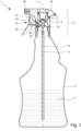
- Fig.1 shows a proposed dispenser 1 with a proposed dispensing device 2 and a container 3.
- a fluid F can be accommodated in the dispenser 1 or container 3.
- the dispensing device 2 is designed or provided for conveying the fluid F from the container 3 and for discharging or dispensing the fluid F.
- the fluid F is preferably a (low-viscosity) liquid, in particular a cleaning fluid or similar, but can also have a viscous to pasty consistency or a high viscosity.
- the fluid F is dispensed with the dispensing device 2 preferably or optionally as a spray or aerosol and/or as a foam.
- the dispensing device 2 preferably or optionally as a spray or aerosol and/or as a foam.
- other solutions are also possible here.
- the dispenser 1 is preferably placed on the market as a disposable article and filled with the fluid F and/or sold to an end customer.
- the dispenser 1 is particularly suitable for cleaning fluids, such as glass cleaner or the like, but can also be used for any other fluids F.
- the dispenser 1 and/or the dispensing device 2 have a (common) central or longitudinal axis L.
- the axis L is preferably aligned at least substantially vertically in a usual storage position and/or use position of the dispenser 1, as also shown in the figures.
- the dispensing device 2 or an outer housing 14 of the dispensing device 2 is usually at the top and the container 3 is at the bottom.
- the axis L at least in the storage position, runs at least substantially parallel to gravity.
- the dispenser 1 In the storage position, the dispenser 1 preferably stands on a base of the container 3.
- an "axial” direction or movement is preferably understood to mean a direction or movement that runs along or parallel to the axis L.
- the term “radial” preferably also refers to the axis L.
- top and bottom as well as modifications thereof and similar terms preferably have the usual general meaning with regard to the preferred orientation or position of use and in the present invention preferably refer to the storage position of the dispenser 1 or the dispensing device 2 shown in the figures.
- the proposed dispensing device 2 has a pivotable actuating lever 21.
- the fluid F is preferably dispensed from the dispenser 1 or the dispensing device 2 by manual actuation or pivoting of the actuating lever 21.
- the dispensing device 2 has a conveying device 4 for conveying the fluid F, in particular from the container 3.
- the conveying device 4 can be actuated by means of the actuating lever 21.
- the conveying device 4 is preferably designed as a pumping device and/or has a pumping device or pump.
- the conveying device 4 is designed to convey or pump the fluid F - preferably only in the unlocked state - from the container 3 into the dispensing device 2 and/or to dispense it from the dispensing device 2 or via a closure or dispensing element 36.
- the fluid F is preferably pumped out of the container 3 and/or dispensed from the dispensing device 2 or via the closure or dispensing element 36.
- the dispensing device 2 or the actuating lever 21 can be locked or is locked in a locking position, in particular in the delivery state. In the locking position, actuation or pivoting of the actuating lever 21 is locked or not possible. In particular, actuation of the conveying device 4 or dispensing of the fluid F is locked or blocked.
- the state of the dispensing device 2 with the actuating lever 21 in the locking position is referred to below as the locking state.
- Fig.1 the dispensing device 2 is shown in the locked state or with the operating lever 21 in the locked position.
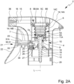
- Fig. 2A is an enlarged view of the dispensing device 2 according to Fig.1 in the locked state.
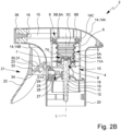
- Fig. 2B shows the dispensing device 2 in a section corresponding to Fig. 2A in an unlocked state or with the actuating lever 21 in an actuating position. In the unlocked state or in the actuating position, manual actuation or manual pivoting of the actuating lever 21 or the conveyor device 4 for dispensing the fluid F is enabled or unlocked.
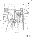
- Fig. 2C shows the dispensing device 2 in a section corresponding to Fig. 2A and Fig. 2B in the actuated state or with actuated, in particular pivoted, actuating lever 21 or with actuated conveyor device 4.
- a preferred structure of the delivery device 2, in particular the conveyor device 4, is described with reference to Fig.1 and Fig. 2A to 2C described in more detail.
- a preferred locking device 27 and securing device 30 are described below.
- this has a bellows 5 or a pumping device is formed by the bellows 5.
- a pumping device is formed by the bellows 5.
- other solutions for a pumping device are also possible.
- a cylinder-piston arrangement is also conceivable, for example similar to that in the US$3,840,157 described cylinder-piston arrangement.
- the conveyor device 4 preferably has a conveyor housing 4A.
- the conveyor housing 4A is preferably at least substantially sleeve-like or ring-like or hollow-cylindrical and/or arranged coaxially to the axis L.
- the pumping device and/or the bellows 5 are preferably arranged at least partially within the conveyor housing 4A or accommodated in the conveyor housing 4A.
- the bellows 5 is preferably arranged within the conveyor housing 4A and/or coaxially thereto.
- the bellows 5 is flexible and/or elastically deformable or the bellows 5 consists of a flexible and/or elastically deformable material.
- the bellows 5 is preferably designed to return, after a deformation, to an initial position assumed before the deformation, or to an inactive position or rest position.
- the bellows 5 is preferably pre-tensioned and/or (slightly) compressed and is installed or arranged in the dispenser 1 or the dispensing device 2 or the conveying device 4 or the conveying housing 4A. This particularly supports reliable conveying of the fluid F.
- the bellows 5 is preferably at least essentially cylindrical or hollow-cylindrical.
- a lateral surface or side wall 6 of the bellows 5 is preferably wavy or corrugated. This preferably increases the flexibility and/or elastic restoring force that drives or moves the bellows 5 back to the starting position or rest position. Furthermore, the wavy design preferably prevents damage when the bellows 5 is deformed and/or increases the stability of the bellows 5.
- the bellows 5 or the side wall 6 preferably runs coaxially to the central or longitudinal axis L of the dispenser 1 or the dispensing device 2.
- the conveying device 4 or the bellows 5 preferably has an inlet 5A for the fluid F, an outlet 5B for the fluid F and a pump chamber or interior space 5C for receiving the fluid F.
- the interior space 5C is preferably formed between the inlet 5A and the outlet 5B and/or is laterally or radially delimited by the side wall 6.
- the conveying device 4 or the bellows 5 has an inlet valve 7 at the inlet 5A and an outlet valve 8 at the outlet 5B.
- the inlet valve 7 and the outlet valve 8 are preferably each designed as a one-way valve.
- the inlet valve 7 enables or controls a supply of the fluid F to the conveying device 4 or the bellows 5.
- the outlet valve 8 enables or controls a discharge of the fluid F from the outlet 5B of the conveying device 4 or the bellows 5.
- the inlet valve 7 and the outlet valve 8 preferably open and/or close in a pressure-controlled or automatic manner, in particular by a pressure difference at the respective valve 7, 8.
- a preferred specific design of the valves 7, 8 will be discussed in more detail later.
- the conveyor device 4 or the bellows 5 preferably has a base 9.
- the base 9 is preferably designed as a component that is separate from the bellows 5 or is manufactured separately.
- the base 9 is preferably axially movable and/or arranged within the conveyor housing 4A.
- the base 9 is connected to the bellows 5, in particular on the inlet side.
- the bellows 5 can be connected to the base 9 in a force-fitting or friction-fitting and/or material-fitting manner or can be fastened to the base 9, in particular locked, glued, welded and/or injection-molded.
- the base 9 preferably has a base element 10.
- the base element 10 is preferably designed in the form of a plate and/or preferably forms a (lower) end surface or a (lower or end-side) closure of the conveyor device 4 or the bellows 5 or the interior space 5C.
- the base element 10 is preferably designed at least substantially in the form of a circular disk and/or forms an annular surface.
- the base 9 preferably has or forms a supply channel 11 for the fluid F, which runs particularly axially or parallel to the axis L.
- the supply channel 11 preferably opens into the inlet 5A of the bellows 5.
- the feed channel 11 is preferably formed or limited by a line 12 of the base 9.
- the line 12 and the base element 10 are preferably formed in one piece.
- the base 9 with the bottom element 10 and the supply line 12 can be designed or manufactured, for example, as an injection-molded component and/or from plastic.
- the base element 10 is preferably arranged at a distance from the upper axial end of the line 12 facing the bellows 5 and/or the lower axial end facing the container 3.
- the line 12 forms a connection and/or projects downwards or into the container 3.
- the dispenser 1 or the dispensing device 2 or the conveying device 4 preferably has a riser 13 for the fluid F.
- the riser 13 is preferably connected to the bellows 5 or the base 9, in particular to the feed channel 11 or the Line 12 is connected and/or arranged at a lower end or at an end of the base 9 or line 12 facing away from the floor element 10 and/or the bellows 5.
- the riser line 13 can be plugged into the line 12 or plugged onto the line 12 or connected to the line 12 in some other way.
- the riser 13 preferably forms an extension of the line 12 or the feed channel 11.
- the line 12 and the riser 13 together form and/or delimit the feed channel 11.
- the dispenser 1 or the dispensing device 2 preferably has an outer housing 14.
- the outer housing 14 forms an outer housing of the dispensing device 2 or a part of an outer housing.
- the conveying device 4 is arranged or held in the outer housing 14.
- the outer housing 14 is designed to accommodate the conveying device 4 and/or the bellows 5.
- the outer housing 14 is designed in two parts, i.e. has an upper housing part 14A and a lower housing part 14B.
- the outer housing 14 is designed in two parts, i.e. has an upper housing part 14A and a lower housing part 14B.
- other solutions are also possible here.
- the dispensing device 2 or conveyor device 4 preferably has or forms an outlet channel 15 which runs in particular transversely or perpendicularly to the axis L.
- the outlet channel 15 is preferably arranged in the outer housing 14.
- the outlet channel 15 is preferably fluidically connected or connectable to the outlet 5B and opens into a channel opening 16.
- the fluid F can preferably exit the outer housing 14 via the outlet channel 15 and the channel opening 16 or be dispensed by the dispenser 1 or the dispensing device 2.
- the outlet channel 15 is preferably formed by the conveyor device 4 or its conveyor housing 4A.
- the outlet channel 15 could also be formed by the outer housing 14, in particular its upper housing part 14A. It is also possible for the outlet channel 15 to be designed as a separate component, which is preferably inserted or can be inserted into the outer housing 14.
- the dispensing device 2 or the outer housing 14 preferably has the closure or dispensing element 36.
- the closure or dispensing element 36 is preferably arranged at or in the direction of the fluid dispensing behind the outlet channel 15 or the channel opening 16.
- the fluid 2 is preferably dispensed at the closure or dispensing element 36 or must first pass through the closure or dispensing element 36 before it can be dispensed.
- the closure or dispensing element 36 can be designed in such a way that when the fluid F passes through, a desired dispensing form of the fluid F is achieved or brought about, for example as a spray or aerosol and/or foam.
- the closure or dispensing element 36 can have a passage opening with a grid (not shown) through which the fluid F must pass before dispensing.
- the closure or dispensing element 36 can be designed to selectively or as required close the channel opening 16 (fluid-tight) and/or to produce different dispensing forms of the fluid F.
- the closure or dispensing element 36 is rotatable in order to selectively arrange different passage openings behind the channel opening 16 and/or to close or cover the channel opening 16 (fluid-tight).
- the outlet channel 15 is preferably arranged off-center on the conveyor housing 4A. It is therefore in Fig.1 and Fig. 2A to 2C behind the cutting plane. Accordingly, a passage opening of the closure or dispensing element 36 is not visible/shown.
- the fluid F preferably passes via the feed channel 11 or the line 12 and/or the riser line 13 from the container 3 into the dispensing device 2 or the conveying device 4 or the bellows 5.
- the inlet valve 7 is designed such that it opens when the fluid F is conveyed by the conveying device 4 or when fluid pressure is present on the feed channel side and thus enables the fluid F to be conveyed from the feed channel 11 through the inlet valve 7 into the interior space 5C of the bellows 5.
- the bellows 5 is preferably in an unactuated position or rest position, which in Fig.1 , 2A and 2 B shown, and in an actuated or compressed position, which is shown in Fig. 2C shown, can be positioned or arranged or can be deformed into these positions.
- the bellows 5 is preferably designed to automatically assume the rest position, in particular by elastic return, or to return to this position if no force deforming the bellows 5 from the rest position acts on the bellows 5.
- the bellows 5 is preferably compressed axially or along the axis L in the actuated position. The compression of the bellows 5 takes place in particular axially or parallel to the axis L and/or by pushing together or folding together the corrugated side wall 6.
- the bellows 5 is preferably held or fastened in a stationary or immovable manner on the outlet side, in particular by or on the conveyor housing 4A and/or the outer housing 14.
- the outlet 5B and/or the conveyor housing 4A do not change their (axial) position relative to the outer housing 14 and/or the container 3 when the bellows 5 is compressed or deformed or when the dispensing device 2 or the dispenser 1 is actuated.
- the bellows 5 is preferably movably held or fastened on the inlet side, in particular by or on the base 9.
- the inlet 5A and/or the base 9 change their (axial) position relative to the conveyor housing 4A, the Outer housing 14 and/or the container 3 upon compression or deformation of the bellows 5 or upon actuation of the dispensing device 2 or the dispenser 1.
- the compression or volume reduction of the bellows 5 causes an increased pressure of the fluid F located in the interior 5C of the bellows 5, so that the fluid F is present at the outlet valve 8 with an increased pressure, through which the outlet valve 8 preferably opens.
- the compression of the bellows 5 therefore preferably causes the fluid F to enter the outlet channel 15 through the outlet valve 8 and to leave the latter via the channel opening 16 or the discharge element 36 and thus to be discharged from or by the discharge device 2.
- the bellows 5 When the actuation of the conveying device 4 is terminated or no compressive force acts on the bellows 5 (anymore), the bellows 5 preferably returns to the rest position, in particular by elastic return.
- the expansion of the bellows 5 from the compressed or actuated position to the rest position reduces the pressure in the interior 5C of the bellows or a negative pressure is created in the bellows 5 or its interior 5C during the expansion, which preferably closes the outlet valve 8.
- the inlet valve 7 is preferably opened by the negative pressure, so that fluid F present in the supply channel 11 at the inlet valve 7 flows or can flow through the inlet valve 7 into the interior 5C of the bellows 5.
- the inlet valve 7 is preferably formed by the line 12 and the bellows 5.
- the inlet valve 7 or the bellows 5 has a valve element 7A formed in one piece with the bellows 5.
- the valve element 7A In a closed position of the inlet valve 7, the valve element 7A preferably closes an end opening 11A of the feed channel 11 or the line 12, or opening into the interior 5C, in a fluid-tight manner.
- the opening 11A is sealed by the valve element 7A - at least in the closed position.
- the valve element 7A is preferably held by one or more, in particular flexible and/or web-like arms of the bellows 5 (not shown).
- the valve element 7A is preferably prestressed, in particular by means of the arms, against the opening 11A or the supply channel 11.
- the outlet valve 8 is preferably formed by a particularly ring-like sealing lip 8A, which - at least in the closed state of the outlet valve 8 - rests sealingly against a counter surface 8B, preferably ring-shaped and/or arranged coaxially to the axis L, and is in particular prestressed against the counter surface 8B.
- a counter surface 8B preferably ring-shaped and/or arranged coaxially to the axis L, and is in particular prestressed against the counter surface 8B.
- the sealing lip 8A In an open position of the outlet valve 8, the sealing lip 8A is lifted off the counter surface 8B, so that a gap is formed between the sealing lip 8A and the counter surface 8B, through which the fluid F can exit from the interior 5C of the bellows 5 and enter the outlet channel 15.
- the conveyor housing 4A has or forms the counter surface 8B.
- the conveyor housing 4A has an opening through which the fluid F enters the outlet channel 15 (not shown).
- the outlet channel 15 is preferably arranged off-center on the conveyor housing 4A and is therefore in Fig.1 and Fig. 2A to 2C behind the cutting plane. Accordingly, the opening in the conveyor housing 4A is not visible/shown in the figures.
- the dispenser 1 or the dispensing device 2 is designed in such a way that when the conveying device 4 is actuated, automatic ventilation of the container 3 takes place or is caused, so that no (too high) negative pressure is created in the dispenser 1 or the container 3 during or through the conveying and/or dispensing of the fluid F from the container 3.
- a negative pressure could lead to a deformation of the container 3 and/or prevent or impede (further) conveying of the fluid F from the container 3, which is undesirable.
- the dispenser 1 or the dispensing device 2 is preferably designed such that when the conveyor device 4 is actuated, in particular when the bellows 5 or the base 9 moves axially, a ventilation gap 17 is formed through which which allows or takes place ventilation of the container 3, as in particular in Fig. 2C shown.
- the dispensing device 2 has or forms a seat or a guide 18 for the base 9 or the line 12.
- the guide 18 is preferably designed to be ring-like and/or hollow-cylindrical, at least in sections.
- the guide 18 is arranged in particular coaxially to the axis L.
- the line 12 is preferably held by the guide 18 or within the guide 18 and/or arranged or can be arranged in the guide 18.
- the ventilation gap 17, in particular ring-shaped can be formed between the line 12 and the guide 18, in particular formed by the line 12 being lifted off or spaced apart from the guide 18 during an axial movement.
- the ventilation gap 17 is formed between the guide 18 and the line 12 when the conveyor device 4 is actuated, in particular when the bellows 5 is compressed or deformed from the rest position into the compressed position and/or when the base 9 is moved axially upwards or in the direction of the bellows 5 or upper housing part 14A.
- the ventilation gap 17 is preferably formed during the axial movement of the base 9 or line 12 in that the line 12 has or forms a (conically) tapered section or a particularly conical taper 19 on the outside, preferably in the region of the guide 18.
- the outer diameter of the line 12 is preferably changed, in particular reduced downwards or with increasing distance from the bellows 5.
- the distance between the line 12 or taper 19 and the guide 18 is changed, in particular increased, particularly in the event of an axial movement of the base 9 or line 12 (in the direction of the bellows 5 or upwards), so that the ventilation gap 17 is formed.
- the dispenser 1 or the dispensing device 2 has an attachment or a connecting part 20.
- Fig.3 shows a preferred embodiment of the connecting part 20 in a perspective view.
- the connecting part 20 has a bearing part 24 for pivotally supporting the actuating lever 21 and/or for forming a pivot axis S. This will be discussed in more detail later.
- the connecting part 20 forms a part or section of an outer housing of the dispenser 1 or the dispensing device 2, in particular together with the outer housing 14.
- the connecting part 20 preferably has or forms the guide 18.
- the dispensing device 2 is attached to the container 3 with or through the connecting part 20.
- the connecting part 20 can, for example, be screwed onto the container 3 and/or connected to the container 3 in a locking manner.
- other solutions are also possible here.
- the connecting part 20 is preferably arranged axially between the container 3 and the bellows 5, the conveyor device 4 and/or the outer housing 14.
- the conveyor device 4 or its conveyor housing 4A and/or the lower housing part 14B are/is preferably arranged (axially) between the connecting part 20 and the upper housing part 14A or connect them to one another.
- the connecting part 20 is preferably connected or connectable, particularly preferably in a locking manner, to the conveyor device 4, in particular the conveyor housing 4A, and/or the outer housing 14, in particular the lower housing part 14B.
- the connecting part 20 preferably has one or more locking elements 20A and/or recesses 20B, as shown in particular in Fig.3
- other solutions are also possible here, for example a screw connection or a material-tight connection.
- the outer housing 14, the upper housing part 14A, the lower housing part 14B, the fastening part 14C, the conveyor housing 4A and/or the connecting part 20 can each be connected to one another in a force-fitting, form-fitting and/or fluid manner, in particular by being locked, screwed, glued, welded or injection-molded. It is also possible for one or more of the parts 14, 14A, 14B, 14C, 4A, 20 to be formed in one piece or to form different sections of a single component.
- the dispensing device 2 or conveying device 4 has the actuating lever 21 for the manual actuation of the dispensing device 2 or the conveying device 4.
- the conveying device 4 is actuated or the bellows 5 is compressed to dispense the fluid F (exclusively) by (manual) actuation of the actuating lever 21 by a user (not shown).
- the actuating lever 21 is preferably pivotably arranged or mounted on the dispensing device 2 or the conveyor housing 4A, outer housing 14 and/or connecting part 20.
- the pivot axis S, about which the actuating lever 21 can pivot - at least in the unlocked state - preferably runs transversely, in particular perpendicularly, to the axis L and/or at least substantially horizontally in the usual position of use.
- the pivot axis S preferably lies or runs within the outer housing 14 and/or between the axis L and the outer housing 14 and/or in the vicinity of the outer housing 14.
- the actuating lever 21 preferably has at its free end an actuating portion 22 and a lever arm 23 coupled in particular to the actuating portion 22 or is formed by these.
- the actuating section 22 preferably extends at least substantially, in particular completely, outside the outer housing 14 and/or conveyor housing 4A.
- the lever arm 23 is preferably arranged, at least in sections or predominantly, within the outer housing 14, in particular the lower housing part 14B, and/or the conveyor housing 4A or projects into it/these.
- the lever arm 23 preferably extends transversely and in particular at least substantially perpendicular to the axis L and/or the pivot axis S.
- the pivot axis S preferably runs or extends through the lever arm 23.
- the outer housing 14, in particular the lower housing part 14B, and/or the conveyor housing 4A has a recess or opening through which the actuating lever 21 or lever arm 23 is or can be passed through.
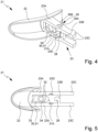
- the operating lever 21 is particularly Fig. 4 and 5 shown.
- Fig.4 is a perspective view of the operating lever 21.
- Fig.5 is a view of the operating lever 21 from below in the normal position of use of the dispenser 1 or the dispensing device 2.
- the actuating portion 22 is preferably designed for manual actuation by a user (not shown).
- the operating section 22 can be curved and/or ergonomically shaped. This is conducive to easy and comfortable operation.
- the lever arm 23 is preferably designed to drive or activate the conveying device 4, in particular to actuate or compress the bellows 5 and/or to move the base 9 axially, in particular upwards or in the direction of the outlet 5B and/or the upper housing part 14A.
- the lever arm 23 is preferably arranged off-center and/or at an end portion of the actuating portion 22, in particular so that the Actuating section 22 so that the greatest possible leverage can be generated during actuation.
- the lever arm 23 and the actuating portion 22 are arranged transversely, in particular at least substantially perpendicularly, to one another.
- the lever arm 23 particularly preferably has two legs 23A that run parallel to one another, in particular in the form of arms or webs, which are connected to or arranged on the actuating section 22 on one side.
- the legs 23A are preferably rigidly connected to one another, for example on or near the end side opposite the actuating section 22, by a section 23B that is arranged transversely or at right angles to the legs 23A. In this way, a lever arm 23 that is both stable and saves material is formed.
- other solutions are also possible here.
- the dispensing device 2 has a bearing part 24 on which the actuating lever 21, in particular the lever arm 23, is movable, in particular pivotable, mounted or can be mounted.
- the connecting part 20 has the bearing part 24 or forms it, as in particular in Fig.3 shown.
- the bearing part 24 can also be arranged on the conveyor device 4, in particular its conveyor housing 4A, the outer housing 14, in particular the lower housing part 14B, or another part of the delivery device 2 or can be formed thereby.
- the bearing part 24 preferably has a bearing element 25, in particular a bearing pin.
- the bearing part 24 preferably has two opposing bearing elements 25.
- the pivot axis S runs through the bearing part or the bearing element(s) 25, and/or is defined by the bearing part 24 or the bearing element(s) 25, as shown in particular in Fig.3 shown.
- the actuating lever 21 preferably has one or more bearing sections 26 corresponding to the bearing part 24 or the bearing element(s) 25.
- the bearing section(s) 26 are preferably recesses for engagement of the bearing element(s) 25 and/or locking elements for locking with the bearing element(s) 25.
- each bearing element 25 engages in each leg 23A of the lever arm 23 or each of the legs 23A has corresponding bearing sections 26 for a bearing element 25.
- bearing part 24 could have one or more bearing sections 26, in particular recesses, and the actuating lever 21, in particular the lever arm 23, could have one or more bearing elements 25.
- Fig. 6A to Fig. 6C show in perspective views the actuating lever 21 connected to the bearing part 24 in three different positions, which correspond to the Fig. 2A to Fig. 2C correspond to the positions shown.
- Fig. 6A shows the operating lever 21 in the locking position, corresponding to Fig. 2A .
- Fig. 6B shows the operating lever 21 in the unlocked, unactuated position or actuating position, corresponding to Fig. 2B .
- Fig. 6C shows the operating lever 21 in the actuated or swivel position, corresponding to Fig. 2C .
- the locking position of the actuating lever 21 or a locking device 27 of the dispensing device 2 is in the Figures 1 , 2A and 6A
- the dispenser 1 or the dispensing device 2 is accordingly in a locked state.
- actuation or pivoting of the actuating lever 21 is blocked.
- activation or actuation of the conveying device 4 and/or dispensing of fluid F is blocked.
- the dispensing device 2 has a locking device 27 which locks or blocks the actuation of the actuating lever 21 or the conveying device 4 in the locked state or in the locked position.
- the locking device 27 or the locking state is preferably realized or formed by a positive connection, in particular of the actuating lever 21 and bearing part 24.
- the locking device 27 preferably has a locking element 28.
- the locking element 28 In the locking position or in the locking state, the locking element 28 preferably engages in a form-fitting manner in a corresponding recess 29.
- the locking device 27 is preferably formed by the locking element 28 and the recess 29 and/or has these.
- the locking element 28 is arranged or formed on the actuating lever 21, in particular on the lever arm 23, particularly preferably on its section 23B, as shown in particular in Fig. 4 and 5 shown.
- the locking element 28 is designed or manufactured in one piece with the actuating lever 21 or lever arm 23.
- the blocking element 28 is preferably cuboid-shaped, in particular at least substantially cube-shaped.
- the bearing part 24 preferably has the recess 29 or forms it, as in particular in Fig.3 shown.
- the recess 29 could also be arranged or formed at another location on the connecting part 20, on the conveyor device 4, in particular its conveyor housing 4A, and/or on the outer housing 14, in particular on the lower housing part 14B.
- the recess 29 is preferably designed to correspond to the locking element 28. Particularly preferably, the recess 29 extends through the bearing part 24 and/or transversely, in particular perpendicularly, to the pivot axis S and/or horizontally or in the radial direction in the position of use.
- the locking element 28 extends in the locking position in the radial direction or in the position of use horizontally into the recess 29, particularly preferably radially outwards or away from the longitudinal axis L and/or radially to the pivot axis S.
- actuating lever 21, in particular the lever arm 23, has the recess 29 and a corresponding locking element 28 is arranged or formed on the connecting part 20, the bearing part 24, the conveyor device 4, in particular the conveyor housing 4A, or the outer housing 14, in particular the lower housing part 14B.
- the positive connection is thus formed in particular between the actuating lever 21 and another component of the dispensing device 2, preferably the bearing part 24, in the locking position or the locking state.
- an actuation or pivoting of the actuating lever 21 is preferably blocked or prevented.
- Fig. 2B and Fig. 6B show the actuating lever 21 or the locking device 27 in the unlocked position or the actuating position in which an actuation of the actuating lever 21 or the conveyor device 4 is possible or enabled.
- the actuating lever 21 and/or the locking device 27 is unlocked and/or the positive connection formed in the locking position or in the locked state is canceled or dissolved.
- the dispenser 1 or the dispensing device 2 is accordingly preferably in an unlocked state.
- the locking element 28 is preferably free in the actuating position or is no longer engaged.
- the locking element 28 is no longer engaged with the recess 29 and/or is arranged (completely) outside the recess 29, particularly preferably in such a way that pivoting of the actuating lever 21, in particular together with the locking element 28, is possible or enabled.
- the actuating lever 21 is preferably (manually) displaceable.
- the actuating lever 21 or the locking element 28 can therefore preferably be displaced or moved from the locking position into the actuating position.
- the locking element 28 is preferably pushed out of the recess 29 and/or the positive locking of the locking device 27 is released.
- the actuating lever 21 is displaceable or pressed linearly and/or in the radial direction, in particular inwards or in the direction of the longitudinal axis L, the bearing part 24 and/or the pivot bearing or pivot axis S.
- the actuating section 22 can preferably be moved or pressed in the direction of the longitudinal axis L, the bearing part 24, the pivot bearing or pivot axis S, the conveyor device 4 and/or the outer housing 14.
- the actuating section 22 is preferably arranged completely outside the outer housing 14.
- the distance between the outer housing 14, in particular the lower housing part 14B, and the actuating section 22, is preferably smaller in the actuating position than in the locking position.
- the lever arm 23 can preferably be pushed (further) into the outer housing 14 and/or the conveyor device 4, in particular the conveyor housing 4A.
- the lever arm 23 is located to a greater extent within the outer housing 14 or the conveyor housing 4A in the actuating position than in the locking position.
- the locking element 28, which is preferably formed in one piece with the lever arm 23, is preferably displaced accordingly, in particular in the direction of the longitudinal axis L.
- actuating lever 21 is moved from the locking position to the actuating position by another movement.
- the actuating lever 21, in particular the lever arm 23, could be partially pullable in order to move from the locking position to the actuating position and/or to release the positive locking of the locking device 27, in particular to pull the locking element 28 out of the recess 29.
- the dispensing device 2 or the actuating lever 21 or the locking device 27 can be locked again after unlocking or can be locked again or can be moved from the actuating position (again) into the locking position.
- the locking or the positive locking realized by the locking device 27 can be restored and/or the locking element 28 can be brought into engagement (again), in particular with the recess 29.
- the actuating lever 21 can be moved linearly in the opposite direction to that in which it was unlocked in order to (again) lock the dispensing device 2 or the actuating lever 21.
- the actuating lever 21, in particular the lever arm 23, can be partially pulled out of the outer housing 14 and/or the conveyor housing 4A and/or moved in the radial direction away from the longitudinal axis L in order to (again) assume the locking position.
- the actuating lever 21 could lock permanently in the actuating position when unlocking or something similar.
- the bearing part 24 and/or the bearing section(s) 26 are/are preferably designed to hold or mount the actuating lever 21, in particular the lever arm 23, in a displaceable manner, in particular such that it can be displaced from the locking position into the actuating position, particularly preferably also back again from the actuating position into the locking position if necessary.
- the bearing part 24 preferably has one or more bearing elements 25, in the example shown two bearing elements 25 arranged on opposite sides, in particular bearing pins.
- the actuating lever 21, in particular the lever arm 23, preferably has corresponding bearing sections 26, in which the bearing elements 25 engage for storage, as in particular in the Fig. 6A to 6C shown.
- the displaceability of the actuating lever 21 is preferably realized by the bearing sections 26.
- the bearing sections 26 are designed in such a way that they enable the actuating lever 21 to be displaced.
- the bearing sections 26 could be designed as elongated holes formed in the lever arm 23, in which the bearing elements 25 of the bearing part 24 are held or mounted so as to be longitudinally displaceable.
- the actuating lever 21 and the bearing part 24 are positively connected to one another in the locking position and/or the actuating position, particularly preferably both in the locking position and the actuating position, in particular locked or lockable.
- the (respective) bearing elements 25 are locked or lockable in the corresponding (respective) bearing sections 26.
- the bearing section 26 has a first partial section 26A and a second partial section 26B.
- the bearing element 25 is held or mounted in the locking position in particular in a latching manner in the first section 26A, as in particular in Fig. 6A shown.
- the bearing element 25 is held or mounted in the actuating position in particular in a latching manner in the second section 26B, as in particular in Fig. 6B shown.
- the pivot axis S runs through the first section 26A in the locking position and/or through the second section 26B in the actuating position. Pivoting of the actuating lever 21 is preferably only possible if the pivot axis S runs through both the bearing element 25 and the section 26B.
- the bearing element 25 When moving, in particular pushing in, the actuating lever 21 or when unlocking, the bearing element 25 is preferably pushed out of the first section 26A and/or pushed into the second section 26B. However, this displacement preferably only takes place relative to the actuating lever 21. In particular, the bearing element 25 is stationary or immobile relative to the bearing part 24, connecting part 20, conveyor housing 4A and/or outer housing 14.
- the bearing section 26 is preferably designed as an eight-shaped recess or the sections 26A, 26B as overlapping, circular recesses.
- the bearing section 26 is preferably designed as an eight-shaped recess or the sections 26A, 26B as overlapping, circular recesses.
- other solutions are also possible here.
- Fig. 2C and Fig. 6C show the operating lever 21 in the actuated position or swivel position.
- the operating lever 21 is between the Fig. 2B and 6B shown inactive position or actuated position and the in Fig. 2C and 6C shown actuated position or swivel position, in particular about the swivel axis S.
- the movement from the actuating position to the pivoting position is preferably carried out by manual actuation or pivoting of the actuating lever 21 by a user (not shown).
- the actuating lever 21 or the lever arm 23 preferably has an arm portion 23C.
- two arm portions 23C are formed by the respective ends of the legs 23A opposite the actuating portion 22.
- the base 9, in particular the base element 10, forms a counter surface or actuating surface for the actuating lever 21 or lever arm 23 or the arm section(s) 23C or has these.
- the actuating lever 21 or lever arm 23, in particular the arm section(s) 23C, preferably rests on the base element 10 or the actuating surface formed thereby and/or acts on it and/or exerts a force on it, in particular when pivoting from the actuating position to the pivoting position.
- the bellows 5 is preferably actuated or compressed and/or deformed or moved from the rest position to the compressed position. This is done in particular by the lever arm 23 rotating about the pivot axis S or the bearing part 24, in particular the bearing element(s) 25, during the actuation or pivoting movement, so that an end of the lever arm 23 or the arm section(s) 23C assigned to or facing the base 9 is raised or moved in the direction of the bellows 5.
- an actuation of the actuating lever 21 or a pivoting of the actuating lever 21 from the actuating position into the pivoting position causes a compression of the bellows 5 and/or a discharge of the fluid F.
- the pivot axis S, the bearing part 24, in particular the bearing elements 25, or the actuating lever 21, in particular the bearing sections 26, are/is preferably arranged such that the smallest possible pivot angle leads to the largest possible stroke of the arm section(s) 23C, and/or that the force acting on the conveyor device 4 - compared to a force acting on the actuating section 22 - is increased.
- the pivot axis S or the bearing elements 25 or bearing sections 26 are/are preferably arranged or formed within the outer housing 14 at the greatest possible distance from the axis L or close to the outer housing 14.
- a movement of the actuating lever 21 from the actuated position or pivot position (back) to the non-actuated position or actuating position takes place automatically or no active movement or actuation of the actuating lever 21 is required.
- a movement from the pivot position to the actuating position can preferably take place by a user releasing the actuating section 22.
- the expansion of the bellows 5 and/or the movement of the actuating lever 21 from the pivot position to the actuating position, in particular caused by the expansion, preferably takes place through the (elastic) restoring force caused by the preceding elastic deformation or compression of the bellows 5.
- the base 9 or the bottom element 10 or the actuating surface formed thereby preferably acts on the actuating lever 21 or lever arm 23 or exerts a force on the actuating lever 21 or lever arm 23, so that the actuating lever 21 is moved or pivoted from the pivot position to the actuating position.
- the pivoting path of the actuating lever 21 is limited, for example by corresponding stops 23D on the actuating lever 21 or lever arm 23, which are particularly Fig. 4 and 5 are shown.
- the actuating lever 21 is supported from below in the actuating position, in particular by supports 35, which are in particular in Fig.3 and Fig. 6A to 6C are shown.
- the pivoting path when pivoting back is limited by the supports 35.
- the dispensing device 2 has a safety device 30.
- the securing device 30 is designed to block unlocking of the dispensing device 2, the actuating lever 21 or the locking device 27 and/or to secure the dispensing device 2, the actuating lever 21 or the locking device 27 against (accidental or undesired) unlocking, in particular to block displacement of the actuating lever 21 from the locking position into the actuating position.
- the position of the safety device 30 in which the unlocking is secured or blocked is referred to below as the safety position. This is particularly important in Fig. 2A shown.
- the dispenser 1 or the dispensing device 2 is preferably both locked by means of the locking device 27 and secured by means of the safety device 30.
- the securing device 30 has a securing element 31 or is formed by such a element.
- the securing element 31 is preferably designed to block unlocking of the dispensing device 2, the actuating lever 21 or the locking device 27 in the securing position, preferably by means of a positive locking.
- the securing element 31 or the securing device 30 prevents the positive locking formed by the locking device 27 from being canceled and/or the locking element 28 from being removed or pushed out of the recess 29.
- the locking element 31 is preferably elongated and/or rod-like.
- the securing device 30 or the securing element 31 acts in the securing position between the actuating section 22 and the outer housing 14, in particular the lower housing part 14B and/or the connecting part 20.
- the locking element 31 is arranged or fixed in the securing position between the actuating section 22 and another part of the dispensing device 2, in particular the outer housing 14 or lower housing part 14B and/or the connecting part 20, so that the actuating lever 21 cannot be moved out of the locking position or is secured against unlocking.
- the securing device 30 or the securing element 31 extends in the securing position transversely, in particular perpendicular to the actuating section 22 and/or at least substantially parallel to the lever arm 23 and/or in the radial direction.
- the securing device 30 or the securing element 31 is arranged or formed between the legs 23A of the lever arm 23.
- the securing device 30 or the securing element 31 is formed integrally with the actuating portion 22 and/or the lever arm 23 or is formed thereon.
- the securing element 31 forms part of the actuating lever 21.
- the securing device 30 or the securing element 31 is integrally connected to the actuating lever 21 or the actuating section 22 and/or the lever arm 23.
- the securing device 30 or the securing element 31 is arranged or held rigidly or immovably on the actuating lever 21.
- the safety device 30 or the safety element 31 has a contact surface 31A with which the safety device 30 or the safety element 31 rests against the outer housing 14, in particular the lower housing part 14B, the connecting part 20 or another (housing) section of the dispensing device 2, in the safety position or before reaching the unlocked Position or actuation position comes into play.
- the system preferably blocks or secures a movement of the actuation lever 21 into the unlocked position or actuation position.
- the actuating lever 21 or the locking device 27 the securing device 30 or the securing element 31 is preferably movable from the securing position into an unlocked position.
- the securing element 31 can preferably be released and/or moved into the unlocked position by applying a force transverse to the main extension direction of the securing element 31.
- the locking element 31 is preferably arranged such that the actuating lever 21 can be displaced or the dispensing device 2, the actuating lever 21 or the locking device 27 can be unlocked, in particular without restriction or hindrance to the unlocking by the securing element 31.
- the locking device 27 or the displacement of the actuating lever 21 is preferably released.
- the securing device 30 or the securing element 31 can be pressed in and/or folded away or upwards, in particular transversely to its longitudinal extension and/or in the axial direction.
- the securing device 30 or the securing element 31 preferably has one or more predetermined breaking points 32, a connecting piece 33 and/or an actuating element 34.
- the actuating element 34 is preferably formed by a protrusion or the like against which a user (not shown) can press in order to press in or actuate or release the securing element 31.
- the holder of the safety element 31 preferably breaks at predetermined breaking points 32 provided for this purpose.
- the predetermined breaking points 32 are in Fig.5 In the example shown, these are designed as connecting pieces or arms between the securing element 31 and the actuating lever 21, in particular the lever arm 23.
- other solutions are also possible here.
- a connecting piece 33 is formed between the actuating section 22 and the securing element 31, via which the securing element 31 can be folded away or up, pushed away or up or folded down, in particular by actuating or pressing the actuating element 34, preferably after breaking the predetermined breaking points 32.
- the connecting piece 33 is preferably designed as a film hinge.
- the securing device 30 or the securing element 31 can also be (completely) removable or broken out from the dispensing device 2, in particular the actuating lever 21.
- the release device 2 If the safety device 30 or the safety element 31 has been moved out of the safety position, in particular folded away or up, pressed in or removed, the release device 2, the actuating lever 21 or the locking device 27 is preferably unlocked or no longer blocked. In particular, the contact surface 31A no longer comes into contact. A movement or shifting of the actuating lever 21 from the locking position to the actuating position is then possible or released.
- Re-securing is preferably not possible. This is achieved in particular by the securing element 31 breaking irreversibly at the predetermined breaking points 32. However, other solutions are also possible here. In particular, if the securing element 31 is held in the securing position by clamping, it would be conceivable to (re-)secure the dispensing device 2, the actuating lever 21 or the locking device 27 by (re-)clamping the securing element 31.
- the security device 30 or the security element 31 preferably serves as an authenticity seal. This is achieved in particular by the fact that it is not possible to secure it again or that the security element 31 breaks irreversibly at the predetermined breaking points 32. A user can therefore tell from the position of the security device 30 or the security element 31, in particular whether it is in the secured position, and/or the state of the security device 30 or the security element 31, in particular whether it has already been activated or removed and/or broken at the predetermined breaking points 32, whether the dispenser 1 or the dispensing device 2 is still in the delivery state or has already been used.
- the actuating lever 21, in particular together with the locking element 28 and/or the securing element 31, is manufactured in one piece and/or in a common manufacturing process, in particular by injection molding.
- the operating lever 21 is placed in the operating position on the connecting part 20 or the bearing part 24, as shown in Fig. 6B shown (but with the safety device 30 or the safety element 31 intact and not as in Fig. 6B shown folded up).
- the actuating lever 21 is preferably moved into the locking position, in particular so that the locking element 28 comes into engagement.
- This position is in Fig. 6A shown.
- a gap is preferably formed between the locking element 31 or its contact surface 31A and the connecting part 20 or the bearing part 24.
- the outer housing 14, in particular the lower housing part 14B is preferably placed on the connecting part 20 from above, in particular connected to it in a locking manner, wherein the gap is preferably filled by the outer housing 14 or the lower housing part 14B, so that the locking element 31 or the contact surface 31A rests against the outer housing 14 or lower housing part 14B.
- the actuating lever 21 is thus locked and secured.
- the proposed locking or safety mechanism of the actuating lever 21 can also be implemented without a pumping device or pump.
- the dispenser 1 or container 3 can be under pressure, in particular by means of a propellant gas.
- the conveying device 4 is preferably designed as a valve or has a valve.
- the delivery device 4 is actuated or the valve is opened, the fluid F is preferably released automatically by the increased pressure from the dispenser 1 or the delivery device 2.
- the delivery device 4 can preferably be controlled or activated, in particular the valve can be opened.
- the dispenser 1 and/or the dispensing device 2 is particularly preferably recyclable or (exclusively) made from recyclable material or recyclable plastic.
- the container 3, the conveyor device 4, the conveyor housing 4A, the bellows 5, the base 9, the riser 13, the outer housing 14, the outlet channel 15, the connecting part 20, the actuating lever 21, the bearing part 24, the locking device 27 or the locking element 28, the safety device 30 or the locking element 31, the closure or dispensing element 36 and/or other components of the dispensing device 2 or the dispenser 1, particularly preferably all components of the dispensing device 2 or the dispenser 1, are made or formed from recyclable material or recyclable plastic and/or from plastic from the polyethylene family.
Landscapes
- Containers And Packaging Bodies Having A Special Means To Remove Contents (AREA)
Description
- Die vorliegende Erfindung betrifft eine Abgabeeinrichtung zur Abgabe eines Fluids nach dem Oberbegriff des Anspruchs 1 und einen Spender zur Abgabe eines Fluids nach dem Oberbegriff des Anspruchs 11.
- Insbesondere betrifft die vorliegende Erfindung einen Spender für die Aufbewahrung und den Austrag bzw. die Abgabe von Reinigungsmitteln oder pharmazeutischen oder kosmetischen Fluiden, insbesondere Flüssigkeiten. In einem Behälter des Spenders kann ein Fluid aufgenommen werden, das mittels einer an dem Behälter befestigten Abgabeeinrichtung aus dem Behälter förderbar und mittels der Abgabeeinrichtung abgebbar ist. Die Abgabe des Fluids kann in verschiedenen Abgabeformen erfolgen, beispielsweise als Spray bzw. Aerosol oder als Schaum.
- Die
WO 2019/175349 A1 betrifft eine Abgabeeinrichtung zur Abgabe eines Fluids, die eine Pumpeinrichtung zur Förderung des Fluids aus einem Behälter aufweist. Die Pumpeinrichtung weist einen Balg zum Pumpen auf und ist mittels eines manuell bediendbaren Betätigungshebels betätigbar. Der Betätigungshebel ist gegen unerwünschte Betätigung sicherbar. In einer ersten Ausführungsform ist ein Betätigungsarm des Betätigungshebels in einer gesicherten Position hochgeklappt, insbesondere an einem Abgabekopf der Abgabeeinrichtung gesichert. In einer zweiten Ausführungsform weist der Betätigungshebel ein relativ zum Betätigungsarm schwenkbares Sperrelement auf, das zwischen dem Betätigungsarm und einem Gehäuse der Abgabeeinrichtung angeordnet werden kann und so ein Verschwenken des Betätigungshebels blockiert. - Die
EP 0 177 898 A1 betrifft eine Sprühflasche mit Betätigungshebel. Ein stabförmiges Element ist über ein Filmscharnier am Gehäuse des Kopfs der Sprühflasche schwenkbar gelagert. Das stabförmige Element kann in einen Abschnitt des Hebels eingreifen, so dass ein Verschwenken des Hebels blockiert ist. - Die
EP 3 552 989 A1 betrifft einen Adapter für Produktspender und einen Produktspender. Der Adapter umfasst einen schwenkbaren Betätigungshebel mit Handgriff, wobei der Betätigungshebel von einer Entriegelungsposition, in welcher der Handgriff zum Öffnen eines Ventils betätigbar ist, in eine Verriegelungsposition überführbar ist, in der eine Betätigung des Handgriffs gesperrt ist. - Die
US 2005/0184093 A1 betrifft einen sperrbaren Abgabekopf. Der Abgabekopf weist zwei Teile auf, wobei ein oberer Teil einen Druckknopf zum Betätigen eines Ventils aufweist und relativ zum unteren Teil drehbar ist. In einer ersten Drehposition kann der Abgabekopf ein Produkt abgeben, während dies in einer zweiten Drehposition nicht möglich ist. - Die
US 2013/0277397 A1 betrifft einen Aerosolspender mit Betätigungshebel. Der Aerosolspender kann eine Sperre aufweisen, um zu verhindern, dass der Hebel ein Aerosolventil betätigt, wobei ein Abgabekopf des Spenders relativ zu einer Basis in eine gesperrten und einer entsperrten Drehposition drehbar ist. - Es ist eine Aufgabe der vorliegenden Erfindung, eine einfache, zuverlässige und/oder sichere Funktion bzw. Handhabung und/oder einen einfachen Aufbau einer Abgabeeinrichtung bzw. eines Spenders zu ermöglichen und/oder eine Betätigung und/oder einen Austritt von Fluid während des Transports eines Spenders auf einfache bzw. kostengünstige Weise zu verhindern.
- Die obige Aufgabe wird gelöst durch eine Abgabeeinrichtung gemäß Anspruch 1 oder durch einen Spender gemäß Anspruch 11. Vorteilhafte Weiterbildungen sind Gegenstand der Unteransprüche.
- Eine vorschlagsgemäße Abgabeeinrichtung ist zur Abgabe eines, insbesondere in einem zugeordneten und/oder mit der Abgabeeinrichtung verbundenen Behälter aufgenommenen, Fluids ausgebildet.
- Die Abgabeeinrichtung weist eine Fördereinrichtung zur Förderung des Fluids auf. Die Fördereinrichtung ist vorzugsweise eine Pumpeinrichtung bzw. als Pumpe ausgebildet oder weist eine solche auf. Besonders bevorzugt weist die Fördereinrichtung bzw. Pumpeinrichtung einen flexiblen Balg zur Förderung des Fluids auf. Insbesondere ist das Fluid durch eine Expansion des Balgs bzw. einen durch die Expansion entstehenden Unterdruck in den Balg hinein förderbar und durch eine Komprimierung des Balgs aus dem Balg abgebbar. Hier sind jedoch auch andere Lösungen möglich. Beispielsweise kann die Pumpeinrichtung statt eines Balgs einen Pumpenkolben oder dergleichen als Förderelement aufweisen. Ferner kann die Fördereinrichtung auch ohne Pumpe bzw. Pumpeinrichtung realisiert sein, beispielsweise bei einem unter Druck stehenden Behälter.
- Die Abgabeeinrichtung weist einen manuell bedienbaren Betätigungshebel zur Betätigung der Fördereinrichtung bzw. Abgabeeinrichtung auf. Der Betätigungshebel ist vorzugsweise schwenkbar an der Abgabeeinrichtung angeordnet bzw. gelagert. Die Abgabeeinrichtung weist hierzu ein korrespondierendes Lagerteil auf, das zur Schwenklagerung des Betätigungshebels ausgebildet ist.
- Vorschlagsgemäß ist der Betätigungshebel mittels einer Sperreinrichtung gegen (unerwünschte) Betätigung in einer Sperrposition sperrbar. Auf diese Weise kann verhindert werden, dass während der Auslieferung bzw. des Transports eines Spenders, der mit einer Flüssigkeit befüllt ist und eine vorschlagsgemäße Abgabeeinrichtung aufweist, ungewollt Fluid aus dem Spender austritt. Insbesondere muss keine zusätzliche bzw. von dem Spender oder der Abgabeeinrichtung separate Transportsicherung vorgesehen bzw. an der Abgabeeinrichtung oder dem Spender angebracht werden. Dies ermöglicht eine kostengünstige Produktion und/oder Lieferung, da insbesondere auf zusätzliche Sicherungen bzw. Sicherungsteile verzichtet werden kann. Insbesondere ist die vorschlagsgemäße Lösung auch besonders umweltfreundlich, da weniger Abfall produziert wird.
- Gemäß einem Aspekt der vorliegenden Erfindung ist die Abgabeeinrichtung bzw. der mit der Abgabeeinrichtung versehene Spender so ausgebildet, dass der Betätigungshebel relativ zum Lagerteil verschiebbar ist, um den Betätigungshebel aus der Sperrposition in eine Betätigungsposition zu bewegen bzw. zu bringen. In der Betätigungsposition ist der Betätigungshebel entsperrt bzw. ein Verschwenken des Betätigungshebels ist freigegeben. Auf diese Weise wird eine Sperreinrichtung realisiert, die einen besonders einfachen bzw. kostengünstigen Aufbau und/oder leicht bzw. komfortabel zu bedienen ist.
- Besonders bevorzugt ist die Sperreinrichtung durch den Betätigungshebel und/oder das Lagerteil gebildet. Somit kann auf zusätzliche Teile verzichtet werden, was einem einfachen bzw. kostengünstigen Aufbau zuträglich ist. Dies ist sowohl einem einfachen und kostengünstigen Aufbau als auch einer leichten und komfortablen Bedienung zuträglich.
- Vorzugsweise ist das Entsperren des Betätigungshebels reversibel. Mit anderen Worten ist es vorzugsweise möglich, den Betätigungshebel bei Bedarf von der Betätigungsposition (wieder) in die Sperrposition zu bewegen bzw. (wieder) zu sperren. Dies ist einer sicheren Handhabung der Abgabeeinrichtung zuträglich.
- Vorzugsweise ist der Betätigungshebel aus der Sperrposition in die Betätigungsposition und/oder aus der Betätigungsposition in die Sperrposition linear oder entlang einer vorzugsweise nur leicht gebogenen Kurvenbahn verschiebbar. Dies ist einem einfachen Aufbau und einer einfachen bzw. komfortablen Bedienung zuträglich.
- Der Betätigungshebel ist vorzugsweise rastend aus der Sperrposition in die Betätigungsposition und/oder aus der Betätigungsposition in die Sperrposition verschiebbar. Dies ist einem einfachen und/oder sicheren Aufbau und einer einfachen und/oder sicheren Bedienung zuträglich.
- Vorzugsweise ist der Betätigungshebel in der Sperrposition und/oder Betätigungsposition verrastet bzw. rastend gehalten. Insbesondere muss eine bestimmte Haltekraft überwunden werden, um den Betätigungshebel aus der Sperrposition in die Betätigungsposition zu verschieben, oder umgekehrt. Auf diese Weise kann sichergestellt werden, dass die Abgabeeinrichtung bzw. der Betätigungshebel nicht versehentlich entsperrt bzw. gesperrt wird.
- Vorzugsweise rastet der Betätigungshebel selbsttätig beim Entsperren in die Betätigungsposition und/oder beim (erneuten) Sperren in die Sperrposition ein. Ferner kann das Einrasten hörbar und/oder spürbar sein, so dass ein Nutzer eine auditive und/oder haptische Rückmeldung erhält, dass der Betätigungshebel die Betätigungsposition bzw. Sperrposition eingenommen hat. Dies ist einer einfachen bzw. komfortablen Bedienung zuträglich.
- Bevorzugt ist der Betätigungshebel zum Entsperren in Richtung eines Gehäuses der Abgabeeinrichtung drückbar bzw. teilweise in das Gehäuse reindrückbar. Dies ist einer besonders einfachen Handhabung zuträglich. Insbesondere kann der Betätigungshebel in einer fließenden Handbewegung zunächst (rein)gedrückt werden, so dass er aus der Sperrposition in die Betätigungsposition verschoben wird und anschließend heruntergedrückt bzw. verschwenkt werden, um die Abgabeeinrichtung zu betätigen bzw. das Fluid abzugeben. Entsprechend ist der Betätigungshebel zum (erneuten) Sperren vorzugsweise in die entgegengesetzte Richtung ziehbar bzw. herausziehbar.
- Vorzugsweise ist der Betätigungshebel durch einen Formschluss in der Sperrposition gegen Verschwenken gesperrt. Auf diese Weise wird eine besonders einfache Sperreinrichtung realisiert.
- Die Sperreinrichtung, insbesondere der Betätigungshebel oder das Lagerteil, weist vorzugsweise ein Sperrelement auf, wobei das Sperrelement in der Sperrposition ein Verschwenken des Betätigungshebels, insbesondere formschlüssig, blockiert und in der Betätigungsposition freigibt. Insbesondere greift das Sperrelement in der Sperrposition in eine korrespondierende Ausnehmung der Sperreinrichtung ein. Hierdurch wird eine besonders einfache Sperreinrichtung bzw. Sperrung realisiert.
- Besonderes bevorzugt ist das Sperrelement am Betätigungshebel und die Ausnehmung am Lagerteil angeordnet bzw. davon gebildet oder umgekehrt das Sperrelement am Lagerteil und die Ausnehmung am Betätigungshebel. Hierdurch kann auf zusätzliche Teile verzichtet werden und/oder eine besonders einfach aufgebaute Sperreinrichtung realisiert werden.
- Gemäß einem weiteren Aspekt der vorliegenden Erfindung weist die Abgabeeinrichtung bzw. der mit der Abgabeeinrichtung versehene Spender - zusätzlich zu der Sperreinrichtung - eine Sicherungseinrichtung auf. Die Sicherungseinrichtung ist dazu ausgebildet, die Abgabeeinrichtung bzw. den Betätigungshebel bzw. die Sperreinrichtung gegen ein Entsperren zu sichern. Ein direktes Entsperren der Sperreinrichtung - zumindest bei erstmaliger Benutzung - wird vorzugsweise durch die Sicherungseinrichtung verhindert bzw. blockiert. Insbesondere muss zunächst die Sicherungseinrichtung betätigt bzw. die Sperreinrichtung entsichert werden. Dies ist einem besonders sicheren Aufbau bzw. Transport zuträglich, insbesondere da die Abgabeeinrichtung bzw. der Betätigungshebel doppelt gesichert bzw. gesperrt ist.
- Zur Unterscheidung der Sperreinrichtung und der Sicherungseinrichtung werden im Folgenden entsprechende Begrifflichkeiten benutzt. Begriffe wie "sperren", "entsperren", "Sperrung", "Sperrelement", etc. beziehen sich vorzugsweise ausschließlich auf die Sperreinrichtung, sofern nicht explizit anders erwähnt. Entsprechend beziehen sich Begriffe wie "sichern", "entsichern", "Sicherung", "Sicherungselement", etc. vorzugsweise ausschließlich auf die Sicherungseinrichtung, sofern nicht explizit anders erwähnt.
- Das Entsichern der Abgabeeinrichtung, der Sperreinrichtung bzw. des Betätigungshebels ist vorzugsweise irreversibel. Insbesondere kann die Sicherungseinrichtung nur einmalig bzw. nur vor dem ersten Gebrauch betätigt bzw. entsichert werden. Ein erneutes Sichern mittels der Sicherungseinrichtung ist vorzugsweise nicht möglich. Vorzugsweise ist es im Anschluss bei Bedarf ausreichend die Abgabeeinrichtung bzw. den Betätigungshebel mittels der Sperreinrichtung zu sperren. Dies ist einer besonders einfachen Handhabung zuträglich.
- Die Sicherungseinrichtung dient vorzugsweise als Originalitätssiegel bzw. -verschluss. Über den Zustand bzw. die Position der Sicherungseinrichtung (betätigt/entsichert oder unbetätigt/gesichert) kann ein Nutzer vorzugsweise erkennen, ob sich die Abgabeeinrichtung im Auslieferungszustand befindet oder bereits verwendet/entsichert wurde. Dies ist einer sicheren Handhabung zuträglich.
- Die Sicherungseinrichtung weist ein Sicherungselement auf, das das Entsperren des Betätigungshebels, insbesondere ein Verschieben des Betätigungshebels von der Sperrposition in die Betätigungsposition, vorzugsweise formschlüssig, blockiert.
- Das Sicherungselement ist am Betätigungshebel angeordnet oder von diesem gebildet. Hierdurch wird ein besonders einfacher Aufbau der Sicherungseinrichtung realisiert. Vorzugsweise ist das Sicherungselement einstückig mit dem Betätigungshebel gebildet.
- Vorzugsweise ist das Sicherungselement, insbesondere in seiner Sicherungsposition, derart angeordnet, dass es ein insbesondere lineares Verschieben, insbesondere ein (Rein)drücken, des Betätigungshebels blockiert. Besonders bevorzugt liegt das Sicherungselement, insbesondere in seiner Sicherungsposition, am Gehäuse der Abgabeeinrichtung an oder kommt vor Erreichen der Betätigungsposition zur Anlage, so dass das Verschieben bzw. (Rein)drücken des Betätigungshebels verhindert bzw. blockiert ist.
- Vorzugsweise ist das Sicherungselement in seiner Sicherungsposition stoffschlüssig und/oder durch eine Sollbruchstelle vorzugsweise an dem Betätigungshebel gehalten. Dies ist einem besonders einfachen Aufbau zuträglich. Insbesondere kann so auf besonders einfache Weise realisiert werden, dass das Entsichern irreversibel ist.
- Zum Entsichern bzw. zum Freigeben der Sperreinrichtung bzw. der Verschiebbarkeit des Betätigungshebels ist das Sicherungselement aus seiner Sicherungsposition bringbar. Besonders bevorzugt ist das Sicherungselement hierzu eindrückbar, weg- oder hochklappbar und/oder von der Abgabeeinrichtung bzw. dem Betätigungshebel entfernbar, zum Beispiel durch Herausbrechen. Hierdurch wird ein besonders einfaches Entsichern ermöglicht. Ferner zeigt ein fehlendes, eingedrücktes oder hochgeklapptes Sicherungselement an, dass die Abgabeeinrichtung, der Betätigungshebel bzw. die Sperreinrichtung entsichert ist. Die Funktion als Originalitätssiegel ist somit auf besonders einfache Weise realisiert.
- Der vorschlagsgemäße Spender zur Abgabe eines Fluids ist mit der vorschlagsgemäßen Abgabeeinrichtung und einem Behälter versehen. Das Fluid ist mit der Abgabeeinrichtung aus dem Behälter förderbar und mittels der Abgabeeinrichtung von dem Spender abgebbar. So ergeben sich die entsprechenden Vorteile.
- Weitere Aspekte, Merkmale, Vorteile und Eigenschaften der vorliegenden Erfindung ergeben sich aus den Ansprüchen und der nachfolgenden Beschreibung einer bevorzugten Ausführungsform anhand der Zeichnung. Es zeigt:
- Fig. 1
- einen Schnitt eines vorschlagsgemäßen Spenders mit einer vorschlagsgemäßen Abgabevorrichtung;
- Fig. 2A
- einen vergrößerten Schnitt der Abgabeeinrichtung in einem Sperrzustand;
- Fig. 2B
- einen Schnitt der Abgabeeinrichtung in einem entsperrten Zustand;
- Fig. 2C
- einen Schnitt der Abgabeeinrichtung bei betätigter Fördereinrichtung;
- Fig. 3
- eine perspektivische Darstellung eines Verbindungsteils der Abgabeeinrichtung mit einem Lagerteil für einen Betätigungshebel;
- Fig. 4
- eine perspektivische Darstellung eines Betätigungshebels der Abgabeeinrichtung;
- Fig. 5
- eine Ansicht des Betätigungshebels von unten;
- Fig. 6A
- eine perspektivische Darstellung des Betätigungshebels und Verbindungsteils im Sperrzustand;
- Fig. 6B
- eine perspektivische Darstellung gemäß
Fig. 6A im entsperrten Zustand; und - Fig. 6C
- eine perspektivische Darstellung gemäß
Fig. 6A im betätigten Zustand. - In den Figuren werden für gleiche oder gleichartige Komponenten und Einrichtungen die gleichen Bezugszeichen verwendet, wobei sich die gleichen oder entsprechende Vorteile und Eigenschaften ergeben können, auch wenn eine wiederholte Beschreibung weggelassen ist.
-
Fig. 1 zeigt einen vorschlagsgemäßen Spender 1 mit einer vorschlagsgemäßen Abgabeeinrichtung 2 und einem Behälter 3. - In dem Spender 1 bzw. Behälter 3 kann ein Fluid F aufgenommen sein. Die Abgabeeinrichtung 2 ist zur Förderung des Fluids F aus dem Behälter 3 und zum Austrag bzw. zur Abgabe des Fluids F ausgebildet bzw. vorgesehen.
- Das Fluid F ist vorzugsweise eine (niedrigviskose) Flüssigkeit, insbesondere eine Reinigungsflüssigkeit oder ähnliches, kann jedoch auch eine zähflüssige bis pastöse Konsistenz bzw. eine hohe Viskosität aufweisen.
- Die Abgabe des Fluids F mit der Abgabeeinrichtung 2 erfolgt vorzugsweise oder wahlweise als Spray bzw. Aerosol und/oder als Schaum. Hier sind jedoch auch andere Lösungen möglich.
- Der Spender 1 wird vorzugsweise als Einwegartikel und mit dem Fluid F befüllt in den Handel gebracht und/oder an einen Endkunden verkauft. Der Spender 1 ist besonders für Reinigungsflüssigkeiten, wie Glasreiniger oder dergleichen, geeignet, kann jedoch auch für beliebige andere Fluide F eingesetzt werden.
- Vorzugsweise weisen/weist der Spender 1 und/oder die Abgabeeinrichtung 2 eine (gemeinsame) Zentral- oder Längsachse L auf.
- Die Achse L ist vorzugsweise in einer üblichen Lagerposition und/oder Benutzungsposition des Spenders 1 zumindest im Wesentlichen lotrecht (vertikal) ausgerichtet, wie auch in den Figuren dargestellt. Insbesondere beim Gebrauch ist die Abgabevorrichtung 2 bzw. ein Außengehäuse 14 der Abgabevorrichtung 2 üblicherweise oben und der Behälter 3 unten. Insbesondere verläuft die Achse L, zumindest in der Lagerposition, zumindest im Wesentlichen parallel zur Schwerkraft. In der Lagerposition steht der Spender 1 vorzugsweise auf einem Boden des Behälters 3.
- Unter einer "axialen" Richtung bzw. Bewegung wird bei der vorliegenden Erfindung vorzugsweise eine Richtung bzw. Bewegung verstanden, die entlang oder parallel zu der Achse L verläuft. In analoger Weise bezieht sich die Bezeichnung "radial" vorzugsweise ebenfalls auf die Achse L.
- Die Begriffe "oben" und "unten" sowie Abwandlungen davon und dazu ähnliche Begriffe haben bei der vorliegenden Erfindung vorzugsweise die übliche allgemeinsprachliche Bedeutung bezüglich der bevorzugten Ausrichtung bzw. Gebrauchslage und beziehen sich bei der vorliegenden Erfindung vorzugsweise auf die in den Figuren dargestellte Lagerposition des Spenders 1 bzw. der Abgabeeinrichtung 2.
- Die vorschlagsgemäße Abgabeeinrichtung 2 weist einen schwenkbaren Betätigungshebel 21 auf. Eine Abgabe des Fluids F von dem Spender 1 bzw. der Abgabeeinrichtung 2 erfolgt vorzugsweise durch manuelle Betätigung bzw. Verschwenken des Betätigungshebels 21.
- Die Abgabeeinrichtung 2 weist eine Fördereinrichtung 4 zur Förderung des Fluids F, insbesondere aus dem Behälter 3, auf. Die Fördereinrichtung 4 ist mittels des Betätigungshebels 21 betätigbar.
- Bei der dargestellten bevorzugten Ausführungsform ist die Fördereinrichtung 4 vorzugsweise als Pumpeinrichtung ausgebildet und/oder weist eine Pumpeinrichtung bzw. Pumpe auf. Insbesondere ist die Fördereinrichtung 4 dazu ausgebildet, das Fluid F - vorzugsweise nur im entsperrten Zustand - aus dem Behälter 3 in die Abgabeeinrichtung 2 zu fördern bzw. pumpen und/oder von der Abgabeeinrichtung 2 bzw. über ein Verschluss- bzw. Abgabeelement 36 abzugeben. Durch manuelles Betätigen bzw. Verschwenken des Betätigungshebels 21 wird vorzugsweise das Fluid F aus dem Behälter 3 gepumpt und/oder von der Abgabeeinrichtung 2 bzw. über das Verschluss- bzw. Abgabeelement 36 abgegeben.
- Vorschlagsgemäß ist die Abgabeeinrichtung 2 bzw. der Betätigungshebel 21 in einer Sperrposition sperrbar bzw. gesperrt, insbesondere im Auslieferungszustand. In der Sperrposition ist eine Betätigung bzw. ein Verschwenken des Betätigungshebels 21 gesperrt bzw. nicht möglich. Insbesondere ist eine Betätigung der Fördereinrichtung 4 bzw. eine Abgabe des Fluids F gesperrt bzw. blockiert. Der Zustand der Abgabeeinrichtung 2 mit dem Betätigungshebel 21 in Sperrposition wird im Folgenden als Sperrzustand bezeichnet.
- In
Fig. 1 ist die Abgabeeinrichtung 2 im Sperrzustand gezeigt bzw. mit dem Betätigungshebel 21 in Sperrposition.Fig. 2A ist eine vergrößerte Darstellung der Abgabeeinrichtung 2 gemäßFig. 1 im Sperrzustand. -
Fig. 2B zeigt die Abgabeeinrichtung 2 in einem Schnitt korrespondierend zuFig. 2A in einem entsperrten Zustand bzw. mit dem Betätigungshebel 21 in einer Betätigungsposition. Im entsperrten Zustand bzw. in der Betätigungsposition ist eine manuelle Betätigung bzw. ein manuelles Verschwenken des Betätigungshebels 21 bzw. der Fördereinrichtung 4 zur Abgabe des Fluids F freigegeben bzw. entsperrt. -
Fig. 2C zeigt die Abgabeeinrichtung 2 in einem Schnitt korrespondierend zuFig. 2A undFig. 2B im betätigten Zustand bzw. mit betätigtem, insbesondere verschwenktem, Betätigungshebel 21 bzw. mit betätigter Fördereinrichtung 4. - Im Folgenden wird zunächst ein bevorzugter Aufbau der Abgabeeinrichtung 2, insbesondere der Fördereinrichtung 4, anhand von
Fig. 1 undFig. 2A bis 2C näher beschrieben. Eine bevorzugte Sperreinrichtung 27 und Sicherungseinrichtung 30 werden anschließend beschrieben. - Die im Folgenden beschriebene Ausbildung der Fördereinrichtung 4 als Pumpeinrichtung ist bevorzugt, aber nicht wesentlich. Die nachfolgende Darstellung ist daher lediglich beispielhaft.
- Bei der dargestellten bevorzugten Ausführungsform der Fördereinrichtung 4 weist diese einen Balg 5 auf oder wird eine Pumpeinrichtung durch den Balg 5 gebildet. Anstelle des Balgs 5 sind jedoch auch andere Lösungen für eine Pumpeinrichtung möglich. Beispielsweise ist anstatt des Balgs 5 auch eine Zylinder-Kolben-Anordnung denkbar, beispielsweise ähnlich zu der in der
US 3,840,157 beschriebenen Zylinder-Kolben-Anordnung. - Die Fördereinrichtung 4 weist vorzugsweise ein Fördergehäuse 4A auf. Das Fördergehäuse 4A ist vorzugsweise zumindest im Wesentlichen hülsen- oder ringartig bzw. hohlzylindrisch ausgebildet und/oder koaxial zur Achse L angeordnet.
- Die Pumpeinrichtung und/oder der Balg 5 sind vorzugsweise zumindest teilweise innerhalb des Fördergehäuses 4A angeordnet oder in dem Fördergehäuse 4A aufgenommen. Vorzugsweise ist der Balg 5 innerhalb des Fördergehäuses 4A und/oder koaxial zu diesem angeordnet.
- Vorzugsweise ist der Balg 5 flexibel und/oder elastisch verformbar bzw. besteht der Balg 5 aus einem flexiblen und/oder elastisch verformbaren Material.
- Der Balg 5 ist vorzugsweise dazu ausgebildet, nach einer Verformung in eine vor der Verformung eingenommene Ausgangsposition bzw. unbetätigte Position bzw. Ruheposition zurückzukehren.
- Der Balg 5 ist vorzugsweise vorgespannt und/oder (leicht) komprimiert in den Spender 1 bzw. die Abgabeeinrichtung 2 bzw. die Fördereinrichtung 4 bzw. das Fördergehäuse 4A eingebaut bzw. darin angeordnet. Dies unterstützt insbesondere eine zuverlässige Förderung des Fluids F.
- Der Balg 5 ist vorzugsweise zumindest im Wesentlichen zylindrisch bzw. hohlzylindrisch ausgebildet. Eine Mantelfläche bzw. Seitenwand 6 des Balgs 5 ist vorzugsweise wellig bzw. gewellt ausgebildet. Vorzugsweise wird hierdurch die Flexibilität und/oder elastische Rückstellkraft, die den Balg 5 in die Ausgangsposition bzw. Ruheposition zurücktreibt bzw. zurückbewegt, erhöht. Des Weiteren werden durch die wellige Ausführung vorzugsweise Beschädigungen bei einer Verformung des Balgs 5 vermieden und/oder wird die Stabilität des Balgs 5 erhöht.
- Der Balg 5 bzw. die Seitenwand 6 verläuft vorzugsweise koaxial zu der Zentral- oder Längsachse L des Spenders 1 bzw. der Abgabeeinrichtung 2.
- Die Fördereinrichtung 4 bzw. der Balg 5 weist vorzugsweise einen Einlass 5A für das Fluid F, einen Auslass 5B für das Fluid F und einen Pumpraum bzw. Innenraum 5C zur Aufnahme des Fluids F auf. Der Innenraum 5C ist vorzugsweise zwischen dem Einlass 5A und dem Auslass 5B gebildet und/oder durch die Seitenwand 6 seitlich bzw. radial begrenzt.
- Vorzugsweise weist die Fördereinrichtung 4 bzw. der Balg 5 am Einlass 5A ein Einlassventil 7 und am Auslass 5B ein Auslassventil 8 auf. Das Einlassventil 7 und das Auslassventil 8 sind vorzugsweise jeweils als Einwegventil ausgebildet. Das Einlassventil 7 ermöglicht bzw. steuert eine Zufuhr des Fluids F zu der Fördereinrichtung 4 bzw. dem Balg 5. Das Auslassventil 8 ermöglicht bzw. steuert eine Abgabe des Fluids F aus dem Auslass 5B der Fördereinrichtung 4 bzw. des Balgs 5.
- Das Einlassventil 7 und das Auslassventil 8 öffnen und/oder schließen vorzugsweise druckgesteuert bzw. selbsttätig, insbesondere durch eine an dem jeweiligen Ventil 7, 8 anstehende Druckdifferenz. Auf eine bevorzugte konkrete Ausbildung der Ventile 7, 8 wird später noch genauer eingegangen.
- Die Fördereinrichtung 4 bzw. der Balg 5 weist vorzugsweise eine Basis 9 auf. Die Basis 9 ist vorzugsweise als von dem Balg 5 getrenntes bzw. separat hergestelltes Bauteil ausgebildet.
- Die Basis 9 ist vorzugsweise axial bewegbar und/oder innerhalb des Fördergehäuses 4A angeordnet.
- Die Basis 9 ist, insbesondere einlassseitig, mit dem Balg 5 verbunden. Der Balg 5 kann kraft- bzw. reibschlüssig und/oder stoffschlüssig mit der Basis 9 verbunden bzw. an der Basis 9 befestigt sein, insbesondere verrastet, verklebt, verschweißt und/oder angespritzt.
- Die Basis 9 weist vorzugsweise ein Bodenelement 10 auf. Das Bodenelement 10 ist vorzugsweise plattenartig ausgebildet und/oder bildet vorzugsweise eine (untere) Abschlussfläche bzw. einen (unteren bzw. endseitigen) Verschluss der Fördereinrichtung 4 bzw. des Balgs 5 bzw. des Innenraums 5C. Das Bodenelement 10 ist vorzugsweise zumindest im Wesentlichen kreisscheibenartig ausgebildet und/oder bildet eine Ringfläche.
- Die Basis 9 weist vorzugsweise einen insbesondere axial bzw. parallel zur Achse L verlaufenden Zuführkanal 11 für das Fluid F auf bzw. bildet einen solchen. Vorzugsweise mündet der Zuführkanal 11 in den Einlass 5A des Balgs 5.
- Der Zuführkanal 11 ist vorzugsweise durch eine Leitung 12 der Basis 9 gebildet bzw. begrenzt.
- Die Leitung 12 und das Bodenelement 10 sind vorzugsweise einstückig ausgebildet.
- Die Basis 9 mit dem Bodenelement 10 und der Zuleitung 12 kann beispielsweise als Spritzgussbauteil und/oder aus Kunststoff ausgebildet sein bzw. hergestellt werden.
- Das Bodenelement 10 ist vorzugsweise von dem oberen bzw. dem Balg 5 zugewandten und/oder dem unteren bzw. dem Behälter 3 zugewandten axialen Ende der Leitung 12 beabstandet angeordnet.
- Besonders bevorzugt bildet die Leitung 12 einen Anschluss und/oder ragt nach unten bzw. in den Behälter 3 vor.
- Der Spender 1 bzw. die Abgabeeinrichtung 2 bzw. die Fördereinrichtung 4 weist vorzugsweise eine Steigleitung 13 für das Fluid F auf. Die Steigleitung 13 ist vorzugsweise an den Balg 5 bzw. die Basis 9, insbesondere an den Zuführkanal 11 bzw. die Leitung 12 angeschlossen, und/oder einem unteren Ende bzw. an einem dem Bodenelement 10 und/oder dem Balg 5 abgewandten Ende der Basis 9 bzw. Leitung 12 angeordnet. Die Steigleitung 13 kann in die Leitung 12 eingesteckt oder auf die Leitung 12 aufgesteckt oder auf sonstige Weise mit der Leitung 12 verbunden sein.
- Die Steigleitung 13 bildet vorzugsweise eine Verlängerung der Leitung 12 bzw. des Zuführkanals 11. Vorzugsweise bilden und/oder begrenzen die Leitung 12 und die Steigleitung 13 gemeinsam den Zuführkanal 11.
- Der Spender 1 bzw. die Abgabeeinrichtung 2 weist vorzugsweise ein Außengehäuse 14 auf.
- Vorzugsweise bildet das Außengehäuse 14 ein äußeres Gehäuse der Abgabeeinrichtung 2 oder einen Teil eines äußeren Gehäuses.
- Vorzugsweise ist die Fördereinrichtung 4 im Außengehäuse 14 angeordnet bzw. gehalten. Besonders bevorzugt ist das Außengehäuse 14 dazu ausgebildet, die Fördereinrichtung 4 und/oder den Balg 5 aufzunehmen.
- Beim Darstellungsbeispiel ist das Außengehäuse 14 zweiteilig ausgebildet bzw. weist ein oberes Gehäuseteil 14A und ein unteres Gehäuseteil 14B auf. Hier sind jedoch auch andere Lösungen möglich.
- Das Außengehäuse 14, insbesondere das obere Gehäuseteil 14A, weist vorzugsweise ein Befestigungsteil 14C zur Verbindung bzw. Befestigung der Fördereinrichtung 4 bzw. des Balgs 5 mit/an dem Außengehäuse 14 auf.
- Die Abgabevorrichtung 2 bzw. Fördereinrichtung 4 weist vorzugsweise einen insbesondere quer oder senkrecht zur Achse L verlaufenden Austrittskanal 15 auf oder bildet diesen. Vorzugsweise ist der Austrittskanal 15 im Außengehäuse 14 angeordnet. Der Austrittskanal 15 ist vorzugsweise mit dem Auslass 5B fluidisch verbunden bzw. verbindbar und mündet in eine Kanalöffnung 16. Vorzugsweise kann das Fluid F über den Austrittskanal 15 und die Kanalöffnung 16 aus dem Außengehäuse 14 austreten bzw. von dem Spender 1 bzw. der Abgabeeinrichtung 2 abgegeben werden.
- Beim Darstellungsbeispiel ist der Austrittskanal 15 vorzugsweise von der Fördereinrichtung 4 bzw. deren Fördergehäuse 4A gebildet. Hier sind jedoch auch andere Lösungen möglich. Beispielsweise könnte der Austrittskanal 15 auch von dem Außengehäuse 14, insbesondere dessen oberen Gehäuseteil 14A, gebildet sein. Auch ist es möglich, dass der Austrittskanal 15 als separates Bauteil ausgebildet ist, der vorzugsweise in das Außengehäuse 14 eingesetzt oder einsetzbar ist.
- Wie bereits eingangs erwähnt, weist die Abgabeeinrichtung 2 bzw. das Außengehäuse 14 vorzugsweise das Verschluss- bzw. Abgabeelement 36 auf. Das Verschluss- bzw. Abgabeelement 36 ist vorzugsweise an bzw. in Richtung der Fluidabgabe hinter dem Austrittskanal 15 bzw. der Kanalöffnung 16 angeordnet. Das Fluid 2 wird vorzugsweise an dem Verschluss- bzw. Abgabeelement 36 abgegeben bzw. muss erst das Verschluss- bzw. Abgabeelement 36 durchtreten, bevor es abgegeben werden kann.
- Das Verschluss- bzw. Abgabeelement 36 kann derart ausgebildet sein, dass beim Durchtreten des Fluids F eine gewünschte Abgabeform des Fluids F erreicht bzw. bewirkt wird, beispielsweise als Spray bzw. Aerosol und/oder Schaum. Insbesondere kann das Verschluss- bzw. Abgabeelement 36 eine Durchtrittsöffnung mit einem Gitter aufweisen (nicht dargestellt), durch welches das Fluid F vor der Abgabe hindurchtreten muss.
- Das Verschluss- bzw. Abgabeelement 36 kann dazu ausgebildet sein, wahlweise bzw. bedarfsweise die Kanalöffnung 16 (fluiddicht) zu verschließen und/oder verschiedene Abgabeformen des Fluids F zu erzeugen.
- Vorzugsweise ist das Verschluss- bzw. Abgabeelement 36 drehbar, um wahlweise verschiedene Durchtrittsöffnungen hinter der Kanalöffnung 16 anzuordnen und/oder um die Kanalöffnung 16 (fluiddicht) zu verschließen bzw. abzudecken.
- Bei der dargestellten, bevorzugten Ausführungsform ist der Austrittskanal 15 vorzugsweise außermittig am Fördergehäuse 4A angeordnet. Er liegt daher in
Fig. 1 undFig. 2A bis 2C hinter der Schnittebene. Entsprechend ist eine Durchtrittsöffnung des Verschluss- bzw. Abgabeelements 36 nicht sichtbar/dargestellt. - Bei einer erstmaligen Benutzung des Spenders 1 kann es erforderlich sein, zunächst einige Male die Fördereinrichtung 4 bzw. den Betätigungshebel 21 zu betätigen, um Luft aus der Fördereinrichtung 4 zu entfernen und/oder erstmalig Fluid F aus dem Behälter 3 in die Abgabeeinrichtung 2 bzw. die Fördereinrichtung 4 bzw. den Balg 5 zu fördern bzw. zu pumpen.
- Bei einer Betätigung der Fördereinrichtung 4 bzw. des Betätigungshebels 21 gelangt vorzugsweise das Fluid F über den Zuführkanal 11 bzw. die Leitung 12 und/oder die Steigleitung 13 von dem Behälter 3 in die Abgabeeinrichtung 2 bzw. die Fördereinrichtung 4 bzw. den Balg 5.
- Vorzugsweise ist das Einlassventil 7 derart ausgebildet, dass es bei einer Förderung des Fluids F mit der Fördereinrichtung 4 bzw. bei zuführkanalseitig anstehenden Fluiddruck öffnet und somit eine Förderung des Fluids F aus dem Zuführkanal 11 durch das Einlassventil 7 in den Innenraum 5C des Balgs 5 ermöglicht.
- Der Balg 5 ist vorzugsweise in einer unbetätigten Position bzw. Ruheposition, die in
Fig. 1 ,2A und2B dargestellt ist, und in einer betätigten bzw. komprimierten Position, die inFig. 2C dargestellt ist, positionierbar oder anordenbar bzw. in diese Positionen verformbar. - Der Balg 5 ist vorzugsweise dazu ausgebildet, selbsttätig die Ruheposition, insbesondere durch elastische Rückstellung, einzunehmen bzw. in diese zurückzukehren, wenn keine den Balg 5 aus der Ruheposition verformende Kraft auf den Balg 5 wirkt. Vorzugsweise ist der Balg 5 in der betätigten Position axial bzw. entlang der Achse L komprimiert. Die Komprimierung des Balgs 5 erfolgt insbesondere axial bzw. parallel zur Achse L und/oder durch ein Zusammenschieben bzw. Zusammenfalten der gewellten Seitenwand 6.
- Der Balg 5 ist auslassseitig vorzugsweise stationär bzw. unbeweglich gehalten oder befestigt, insbesondere durch das bzw. an dem Fördergehäuse 4A und/oder Außengehäuse 14. Vorzugsweise verändern der Auslass 5B und/oder das Fördergehäuse 4A ihre (axiale) Position relativ zu dem Außengehäuse 14 und/oder dem Behälter 3 bei einer Komprimierung oder Verformung des Balgs 5 bzw. bei einer Betätigung der Abgabeeinrichtung 2 bzw. des Spenders 1 nicht.
- Der Balg 5 ist einlassseitig vorzugsweise beweglich gehalten oder befestigt, insbesondere durch die bzw. an der Basis 9. Vorzugsweise verändern der Einlass 5A und/oder die Basis 9 ihre (axiale) Position relativ zu dem Fördergehäuse 4A, dem Außengehäuse 14 und/oder dem Behälter 3 bei einer Komprimierung oder Verformung des Balgs 5 bzw. bei einer Betätigung der Abgabeeinrichtung 2 bzw. der Spenders 1.
- Vorzugsweise erfolgt bei einer bzw. durch eine Betätigung der Fördereinrichtung 4 bzw. des Betätigungshebels 21 eine axiale Bewegung der Basis 9, insbesondere nach oben bzw. in Richtung des Balgs 5, und/oder eine Komprimierung bzw. Volumenverringerung des Balgs 5.
- Die Komprimierung bzw. Volumenverringerung des Balgs 5 bewirkt einen erhöhten Druck des in dem Innenraum 5C des Balgs 5 befindlichen Fluids F, so dass das Fluid F mit einem erhöhten Druck an dem Auslassventil 8 ansteht, durch den das Auslassventil 8 vorzugsweise öffnet.
- Die Komprimierung des Balgs 5 bewirkt also vorzugsweise, dass das Fluid F durch das Auslassventil 8 in den Austrittskanal 15 eintritt und diesen über die Kanalöffnung 16 bzw. das Abgabelement 36 verlässt und somit aus bzw. von der Abgabeeinrichtung 2 abgegeben wird.
- Wenn die Betätigung der Fördereinrichtung 4 beendet wird bzw. auf den Balg 5 keine komprimierende Kraft (mehr) wirkt, kehrt der Balg 5 vorzugsweise wieder, insbesondere durch elastische Rückstellung, in die Ruheposition zurück.
- Vorzugsweise verringert sich durch die Expansion des Balgs 5 von der komprimierten bzw. betätigten Position in die Ruheposition der Druck im Innenraum 5C des Balgs bzw. entsteht in dem Balg 5 bzw. dessen Innenraum 5C bei der Expansion ein Unterdruck, durch den vorzugsweise das Auslassventil 8 schließt. Des Weiteren wird durch den Unterdruck das Einlassventil 7 vorzugsweise geöffnet, so dass in dem Zuführkanal 11 am Einlassventil 7 anstehendes Fluid F durch das Einlassventil 7 in den Innenraum 5C des Balgs 5 strömt bzw. strömen kann.
- Das Einlassventil 7 ist vorzugsweise durch die Leitung 12 und den Balg 5 gebildet. Insbesondere weist das Einlassventil 7 bzw. der Balg 5 ein einteilig mit dem Balg 5 ausgebildetes Ventilelement 7A auf. Vorzugsweise verschließt das Ventilelement 7A in einer geschlossenen Stellung des Einlassventils 7 eine endseitige bzw. in den Innenraum 5C mündende Öffnung 11A des Zuführkanals 11 bzw. der Leitung 12 fluiddicht. Insbesondere wird die Öffnung 11A durch das Ventilelement 7A - zumindest in der geschlossenen Stellung - dichtend abgedeckt.
- Das Ventilelement 7A ist vorzugsweise durch einen oder mehrere, insbesondere flexible und/oder stegartige Arme des Balgs 5 gehalten (nicht dargestellt). Das Ventilelement 7A ist vorzugsweise, insbesondere mittels der Arme, gegen die Öffnung 11A bzw. den Zuführkanal 11 vorgespannt.
- Das Auslassventil 8 ist vorzugsweise durch eine insbesondere ringartige Dichtlippe 8A gebildet, die - zumindest im geschlossenen Zustand des Auslassventils 8 - an einer, vorzugsweise ringartig ausgebildeten und/oder koaxial zur Achse L angeordneten, Gegenfläche 8B dichtend anliegt, insbesondere gegen die Gegenfläche 8B vorgespannt ist. In einer geöffneten Stellung des Auslassventils 8 ist die Dichtlippe 8A von der Gegenfläche 8B abgehoben, so dass zwischen der Dichtlippe 8A und der Gegenfläche 8B ein Spalt gebildet ist, durch den das Fluid F aus dem Innenraum 5C des Balgs 5 austreten und in den Austrittskanal 15 eintreten kann.
- Vorzugsweise weist das Fördergehäuse 4A die Gegenfläche 8B auf oder bildet diese.
- Vorzugsweise weist das Fördergehäuse 4A eine Durchbrechung auf, durch die das Fluid F in den Austrittskanal 15 gelangt (nicht dargestellt). Wie bereits erwähnt, ist bei der dargestellten, bevorzugten Ausführungsform der Austrittskanal 15 vorzugsweise außermittig am Fördergehäuse 4A angeordnet und liegt daher in
Fig. 1 undFig. 2A bis 2C hinter der Schnittebene. Entsprechend ist die Durchbrechung im Fördergehäuse 4A in den Figuren nicht sichtbar/dargestellt. - Vorzugsweise ist der Spender 1 bzw. die Abgabeeinrichtung 2 derart ausgebildet, dass bei einer Betätigung der Fördereinrichtung 4 eine automatische Belüftung des Behälters 3 erfolgt bzw. bewirkt wird, so dass bei der bzw. durch die Förderung und/oder Abgabe des Fluids F aus dem Behälter 3 kein (zu hoher) Unterdruck in dem Spender 1 bzw. dem Behälter 3 entsteht. Ein solcher Unterdruck könnte zu einer Verformung des Behälters 3 führen und/oder eine (weitere) Förderung des Fluids F aus dem Behälter 3 verhindern oder erschweren, was unerwünscht ist.
- Der Spender 1 bzw. die Abgabeeinrichtung 2 ist vorzugsweise dazu ausgebildet, dass bei einer Betätigung der Fördereinrichtung 4, insbesondere bei einer Axialbewegung des Balgs 5 bzw. der Basis 9, ein Belüftungsspalt 17 gebildet wird, durch den eine Belüftung des Behälters 3 ermöglicht wird bzw. erfolgt, wie insbesondere in
Fig. 2C dargestellt. - Vorzugsweise weist die Abgabeeinrichtung 2 einen Sitz bzw. eine Führung 18 für die Basis 9 bzw. die Leitung 12 auf oder bildet diese.
- Die Führung 18 ist vorzugsweise zumindest abschnittsweise ringartig und/oder hohlzylindrisch ausgebildet. Die Führung 18 ist insbesondere koaxial zur Achse L angeordnet.
- Die Leitung 12 ist vorzugsweise von der Führung 18 bzw. innerhalb der Führung 18 gehalten und/oder in der Führung 18 angeordnet bzw. anordenbar.
- Vorzugsweise kann der, insbesondere ringartig ausgebildete, Belüftungsspalt 17 zwischen der Leitung 12 und der Führung 18 gebildet werden, insbesondere dadurch gebildet, dass die Leitung 12 bei einer Axialbewegung von der Führung 18 abgehoben bzw. beabstandet wird.
- Insbesondere wird der Belüftungsspalt 17 zwischen der Führung 18 und der Leitung 12 gebildet, wenn die Fördereinrichtung 4 betätigt wird, insbesondere wenn der Balg 5 komprimiert wird bzw. von der Ruheposition in die komprimierte Position verformt wird und/oder wenn die Basis 9 axial nach oben bzw. in Richtung des Balgs 5 bzw. oberen Gehäuseteils 14A bewegt wird.
- Der Belüftungsspalt 17 wird bei der Axialbewegung der Basis 9 bzw. Leitung 12 vorzugsweise dadurch gebildet, dass die Leitung 12 außen einen (konisch) verjüngten Abschnitt bzw. eine insbesondere konische Verjüngung 19 aufweist oder bildet, vorzugsweise im Bereich der Führung 18.
- Durch die Verjüngung 19 ist vorzugsweise der Außendurchmesser der Leitung 12 verändert, insbesondere nach unten bzw. mit zunehmendem Abstand vom Balg 5 verringert.
- Durch die Verjüngung 19 wird insbesondere bei einer Axialbewegung der Basis 9 bzw. Leitung 12 (in Richtung des Balgs 5 bzw. nach oben) der Abstand zwischen der Leitung 12 bzw. Verjüngung 19 und der Führung 18 verändert, insbesondere vergrö-ßert, so dass der Belüftungsspalt 17 gebildet wird.
- Vorzugsweise weist der Spender 1 bzw. die Abgabeeinrichtung 2 einen Aufsatz bzw. ein Verbindungsteil 20 auf.
-
Fig. 3 zeigt eine bevorzugte Ausführungsform des Verbindungsteils 20 in einer perspektivischen Darstellung. - Vorzugsweise weist das Verbindungsteil 20 ein Lagerteil 24 zur Schwenklagerung des Betätigungshebels 21 und/oder zum Bilden einer Schwenkachse S auf. Hierauf wird später noch genauer eingegangen.
- Vorzugsweise bildet das Verbindungsteil 20 einen Teil oder Abschnitt eines äußeren Gehäuses des Spenders 1 bzw. der Abgabeeinrichtung 2, insbesondere zusammen mit dem Außengehäuse 14.
- Das Verbindungsteil 20 weist vorzugsweise die Führung 18 auf oder bildet diese.
- Vorzugsweise ist die Abgabeeinrichtung 2 mit dem bzw. durch das Verbindungsteil 20 an dem Behälter 3 befestigt. Das Verbindungsteil 20 kann beispielsweise auf den Behälter 3 aufgeschraubt und/oder rastend mit dem Behälter 3 verbunden sein bzw. werden. Hier sind jedoch auch andere Lösungen möglich.
- Das Verbindungsteil 20 ist vorzugsweise axial zwischen dem Behälter 3 und dem Balg 5, der Fördereinrichtung 4 und/oder dem Außengehäuse 14 angeordnet.
- Die Fördereinrichtung 4 bzw. dessen Fördergehäuse 4A und/oder das untere Gehäuseteil 14B sind/ist vorzugsweise (axial) zwischen dem Verbindungsteil 20 und dem oberen Gehäuseteil 14A angeordnet oder verbinden/verbindet diese miteinander.
- Das Verbindungsteil 20 ist vorzugsweise mit der Fördereinrichtung 4, insbesondere dem Fördergehäuse 4A, und/oder dem Außengehäuse 14, insbesondere dem unteren Gehäuseteil 14B, verbunden oder verbindbar, besonders bevorzugt rastend. Hierzu weist das Verbindungsteil 20 vorzugsweise ein oder mehrere Rastelemente 20A und/oder Ausnehmungen 20B auf, wie insbesondere in
Fig. 3 dargestellt. Hier sind jedoch auch andere Lösungen möglich, beispielsweise eine Schraubverbindung oder eine stoffschlüssige Verbindung. - Das Außengehäuse 14, das obere Gehäuseteil 14A, das untere Gehäuseteil 14B, das Befestigungsteil 14C, das Fördergehäuse 4A und/oder das Verbindungsteil 20 können jeweils kraftschlüssig, formschlüssig und/oder stoffflüssig miteinander verbunden, insbesondere verrastet, verschraubt, verklebt, verschweißt oder angespritzt, sein. Es ist auch möglich, dass ein oder mehrere der genannten Teile 14, 14A, 14B, 14C, 4A, 20 einstückig ausgebildet sind bzw. verschiedene Abschnitte eines einzelnen Bauteils bilden.
- Die Abgabeeinrichtung 2 bzw. Fördereinrichtung 4 weist den Betätigungshebel 21 zur insbesondere manuellen Betätigung der Abgabeeinrichtung 2 bzw. der Fördereinrichtung 4 auf. Vorzugsweise erfolgt eine Betätigung der Fördereinrichtung 4 bzw. Komprimierung des Balgs 5 zur Abgabe des Fluids F (ausschließlich) durch (manuelle) Betätigung des Betätigungshebels 21 durch einen nicht dargestellten Benutzer.
- Wie bereits erwähnt ist es auch möglich, dass die nachfolgend beschriebenen Eigenschaften und Merkmale des Betätigungshebels 21, insbesondere in Bezug auf die Sicherung/Sperrung gegen Betätigung, unabhängig von der Realisierung der Fördereinrichtung 4 durch einen bzw. mit einem flexiblen Balg und/oder als Pumpeinrichtung erfolgt.
- Der Betätigungshebel 21 ist vorzugsweise schwenkbar an der Abgabeeinrichtung 2 bzw. dem Fördergehäuse 4A, Außengehäuse 14 und/oder Verbindungsteil 20 angeordnet bzw. gelagert.
- Die Schwenkachse S, um die der Betätigungshebel 21 - zumindest im entsperrten Zustand - schwenkbar ist, verläuft vorzugsweise quer, insbesondere senkrecht, zu der Achse L und/oder in der üblichen Gebrauchslage zumindest im Wesentlichen horizontal.
- Die Schwenkachse S liegt bzw. verläuft vorzugsweise innerhalb des Außengehäuses 14 und/oder zwischen der Achse L und dem Außengehäuse 14 und/oder in der Nähe des Außengehäuses 14.
- Der Betätigungshebel 21 weist vorzugsweise an seinem freien Ende einen Betätigungsabschnitt 22 und einen insbesondere mit dem Betätigungsabschnitt 22 gekoppelten Hebelarm 23 auf oder ist durch diese gebildet.
- Der Betätigungsabschnitt 22 erstreckt sich vorzugsweise zumindest im Wesentlichen, insbesondere vollständig, außerhalb des Außengehäuses 14 und/oder Fördergehäuses 4A.
- Der Hebelarm 23 ist vorzugsweise zumindest abschnittsweise oder überwiegend, innerhalb des Außengehäuses 14, insbesondere des unteren Gehäuseteils 14B, und/oder des Fördergehäuses 4A angeordnet oder ragt in dieses/diese hinein.
- Der Hebelarm 23 erstreckt sich vorzugsweise quer und insbesondere zumindest im Wesentlichen senkrecht zur Achse L und/oder zur Schwenkachse S.
- Die Schwenkachse S verläuft bzw. erstreckt sich vorzugsweise durch den Hebelarm 23 hindurch.
- Vorzugsweise weist das Außengehäuse 14, insbesondere das untere Gehäuseteil 14B, und/oder das Fördergehäuse 4A eine Ausnehmung oder Durchbrechung auf, durch die der Betätigungshebel 21 bzw. Hebelarm 23 durchgeführt oder durchführbar ist.
- Der Betätigungshebel 21 ist insbesondere in
Fig. 4 und 5 dargestellt.Fig. 4 ist eine perspektivische Ansicht des Betätigungshebels 21.Fig. 5 ist eine Ansicht des Betätigungshebels 21 von unten bei normaler Gebrauchslage des Spenders 1 bzw. der Abgabeeinrichtung 2. - Der Betätigungsabschnitt 22 ist vorzugsweise zur manuellen Betätigung durch einen nicht dargestellten Benutzer ausgebildet.
- Der Betätigungsabschnitt 22 kann geschwungen bzw. gekrümmt und/oder ergonomisch geformt sein. Dies ist einer leichten und komfortablen Bedienung zuträglich.
- Der Hebelarm 23 ist vorzugsweise zum Antrieb oder zur Aktivierung der Fördereinrichtung 4, insbesondere zur Betätigung bzw. Komprimierung des Balgs 5 und/oder zur axialen Bewegung der Basis 9, insbesondere nach oben bzw. in Richtung des Auslasses 5B und/oder des oberen Gehäuseteils 14A, ausgebildet.
- Der Hebelarm 23 ist vorzugsweise außermittig und/oder an einem endseitigen Abschnitt des Betätigungsabschnitts 22 angeordnet, insbesondere so dass über den Betätigungsabschnitt 22 eine möglichst große Hebelwirkung bei der Betätigung erzeugt werden kann.
- Vorzugsweise sind der Hebelarm 23 und der Betätigungsabschnitt 22 quer, insbesondere zumindest im Wesentlichen senkrecht, zueinander angeordnet.
- Besonders bevorzugt weist der Hebelarm 23 zwei parallel zueinander verlaufende, insbesondere armartig oder stegartig ausgebildete Schenkel 23A auf, die an einer Seite mit dem Betätigungsabschnitt 22 verbunden bzw. an diesem angeordnet sind. Vorzugsweise sind die Schenkel 23A, beispielsweise an oder in der Nähe von der dem Betätigungsabschnitt 22 gegenüberliegenden Endseite, durch einen Abschnitt 23B, der quer bzw. rechtwinklig zu den Schenkeln 23A angeordnet ist, starr miteinander verbunden. Auf diese Weise ist ein zugleich stabiler und materialsparender Hebelarm 23 gebildet. Hier sind jedoch auch andere Lösungen möglich.
- Die Abgabeeinrichtung 2 weist ein Lagerteil 24 auf, an dem der Betätigungshebel 21, insbesondere der Hebelarm 23, bewegbar, insbesondere schwenkbar, gelagert oder lagerbar ist.
- Beim Darstellungsbeispiel weist das Verbindungsteil 20 das Lagerteil 24 auf bzw. bildet dieses, wie insbesondere in
Fig. 3 dargestellt. Hier sind jedoch auch andere Lösungen möglich. Insbesondere kann das Lagerteil 24 auch an der Fördereinrichtung 4, insbesondere deren Fördergehäuse 4A, dem Außengehäuse 14, insbesondere dem unteren Gehäuseteil 14B, oder einem sonstigen Teil der Abgabeeinrichtung 2 angeordnet bzw. davon gebildet sein. - Das Lagerteil 24 weist vorzugsweise ein Lagerelement 25, insbesondere einen Lagerzapfen, auf. Beim Darstellungsbeispiel weist das Lagerteil 24 vorzugsweise zwei gegenüberliegende Lagerelemente 25 auf.
- Vorzugsweise verläuft die Schwenkachse S durch das Lagerteil bzw. das/die Lagerelement(e) 25, und/oder wird durch das Lagerteil 24 bzw. das/die Lagerelement(e) 25 definiert, wie insbesondere in
Fig. 3 dargestellt. - Der Betätigungshebel 21 weist vorzugsweise einen oder mehrere zu dem Lagerteil 24 bzw. dem/den Lagerelement(en) 25 korrespondierende Lagerabschnitte 26 auf. Bei dem/den Lagerabschnitten 26 handelt es sich vorzugsweise um Ausnehmungen für einen Eingriff des/der Lagerelement(e) 25 und/oder Rastelemente zum Verrasten mit dem/den Lagerelement(en) 25.
- Beim Darstellungsbeispiel greift vorzugsweise jeweils ein Lagerelement 25 in jeweils einen Schenkel 23A des Hebelarms 23 ein bzw. weist jeder der Schenkel 23A entsprechende Lagerabschnitte 26 für ein Lagerelement 25 auf.
- Hier sind jedoch auch andere Lösungen möglich. Beispielsweise könnte umgekehrt das Lagerteil 24 einen oder mehrere Lagerabschnitte 26, insbesondere Ausnehmungen, und der Betätigungshebel 21, insbesondere der Hebelarm 23, ein oder mehrere Lagerelemente 25 aufweisen.
-
Fig. 6A bis Fig. 6C zeigen in perspektivischen Darstellungen den mit dem Lagerteil 24 verbundenen Betätigungshebel 21 in drei verschiedenen Positionen, die zu den inFig. 2A bis Fig. 2C dargestellten Positionen korrespondieren.Fig. 6A zeigt den Betätigungshebel 21 in der Sperrposition, korrespondierend zuFig. 2A .Fig. 6B zeigt den Betätigungshebel 21 in der entsperrten, unbetätigten Position bzw. Betätigungsposition, korrespondierend zuFig. 2B .Fig. 6C zeigt den Betätigungshebel 21 in der betätigten bzw. Schwenkposition, korrespondierend zuFig. 2C . - Nachfolgend werden die jeweiligen Positionen des Betätigungshebels 21 und die damit einhergehenden Sperr-/Sicherungs- und Betätigungsmechanismen bzw. -einrichtungen bzw. -zustände näher erläutert.
- Die Sperrposition des Betätigungshebels 21 bzw. einer Sperreinrichtung 27 der Abgabeeinrichtung 2 ist in den
Figuren 1 ,2A und6A dargestellt. Der Spender 1 bzw. die Abgabeeinrichtung 2 befindet sich entsprechend in einem Sperrzustand. - Im Sperrzustand bzw. in der Sperrposition ist ein Betätigen bzw. Verschwenken des Betätigungshebels 21 gesperrt bzw. blockiert. Insbesondere ist eine Aktivierung bzw. Betätigung der Fördereinrichtung 4 und/oder eine Abgabe von Fluid F gesperrt bzw. blockiert.
- Die Abgabeeinrichtung 2 weist eine Sperreinrichtung 27 auf, die die Betätigung des Betätigungshebels 21 bzw. der Fördereinrichtung 4 im Sperrzustand bzw. in der Sperrposition sperrt bzw. blockiert.
- Die Sperreinrichtung 27 bzw. der Sperrzustand ist vorzugsweise durch einen Formschluss, insbesondere des Betätigungshebels 21 und Lagerteils 24, realisiert bzw. gebildet.
- Die Sperreinrichtung 27 weist vorzugsweise ein Sperrelement 28 auf.
- In der Sperrposition bzw. im Sperrzustand greift das Sperrelement 28 vorzugsweise formschlüssig in eine korrespondierende Ausnehmung 29 ein.
- Die Sperreinrichtung 27 ist vorzugsweise durch das Sperrelement 28 und die Ausnehmung 29 gebildet und/oder weist diese auf.
- Beim Darstellungsbeispiel ist das Sperrelement 28 am Betätigungshebel 21, insbesondere am Hebelarm 23, besonders bevorzugt an dessen Abschnitt 23B, angeordnet bzw. gebildet, wie insbesondere in
Fig. 4 und 5 dargestellt. - Vorzugsweise ist das Sperrelement 28 einstückig mit dem Betätigungshebel 21 bzw. Hebelarm 23 ausgebildet bzw. hergestellt.
- Das Sperrelement 28 ist vorzugsweise quaderförmig, insbesondere zumindest im Wesentlichen würfelförmig ausgebildet.
- Beim Darstellungsbeispiel weist vorzugsweise das Lagerteil 24 die Ausnehmung 29 auf bzw. bildet diese, wie insbesondere in
Fig. 3 dargestellt. Hier sind jedoch auch andere Lösungen möglich. Beispielsweise könnte die Ausnehmung 29 auch an einer anderen Stelle des Verbindungsteils 20, an der Fördereinrichtung 4, insbesondere deren Fördergehäuse 4A, und/oder am Außengehäuse 14, insbesondere am unteren Gehäuseteil 14B, angeordnet bzw. gebildet sein. - Die Ausnehmung 29 ist vorzugsweise korrespondierend zum Sperrelement 28 ausgebildet. Besonders bevorzugt erstreckt sich die Ausnehmung 29 durch das Lagerteil 24 und/oder quer, insbesondere senkrecht, zur Schwenkachse S und/oder in Gebrauchslage horizontal bzw. in radialer Richtung.
- Vorzugweise erstreckt sich das Sperrelement 28 in der Sperrposition in radialer Richtung bzw. in Gebrauchslage horizontal in die Ausnehmung 29, besonders bevorzugt radial nach außen bzw. von der Längsachse L weg und/oder radial zur Schwenkachse S.
- Es sind auch Lösungen möglich, bei denen der Betätigungshebel 21, insbesondere der Hebelarm 23, die Ausnehmung 29 aufweist und ein entsprechendes Sperrelement 28 an dem Verbindungsteil 20, dem Lagerteil 24, der Fördereinrichtung 4, insbesondere dem Fördergehäuse 4A, oder dem Außengehäuse 14, insbesondere dem unterem Gehäuseteil 14B, angeordnet oder gebildet ist. Der Formschluss ist also insbesondere zwischen dem Betätigungshebel 21 und einem weiteren Bauteil der Abgabeeinrichtung 2, bevorzugt dem Lagerteil 24, in der Sperrposition bzw. dem Sperrzustand gebildet.
- Durch die Sperreinrichtung 27, insbesondere den Formschluss bzw. den Eingriff des Sperrelements 28 in die Ausnehmung 29 im Sperrzustand, ist vorzugsweise ein Betätigen bzw. Verschwenken des Betätigungshebels 21 gesperrt bzw. blockiert.
-
Fig. 2B undFig. 6B zeigen den Betätigungshebel 21 bzw. die Sperreinrichtung 27 in der entsperrten Position bzw. der Betätigungsposition, in der eine Betätigung des Betätigungshebels 21 bzw. der Fördereinrichtung 4 möglich bzw. freigegeben ist. Insbesondere ist der Betätigungshebel 21 und/oder die Sperreinrichtung 27 entsperrt und/oder der in der Sperrposition bzw. im Sperrzustand gebildete Formschluss aufgehoben bzw. aufgelöst. Der Spender 1 bzw. die Abgabeeinrichtung 2 befindet sich entsprechend vorzugsweise in einem entsperrten Zustand. - Das Sperrelement 28 ist in der Betätigungsposition vorzugsweise frei bzw. steht nicht (mehr) im Eingriff. Insbesondere steht das Sperrelement 28 nicht (mehr) mit der Ausnehmung 29 im Eingriff und/oder ist (vollständig) außerhalb der Ausnehmung 29 angeordnet, besonders bevorzugt so, dass ein Verschwenken des Betätigungshebels 21, insbesondere zusammen mit dem Sperrelement 28, möglich bzw. freigegeben ist.
- Zum Entsperren bzw. zum Einnehmen der Betätigungsposition ist der Betätigungshebel 21 vorzugsweise (manuell) verschiebbar. Der Betätigungshebel 21 bzw. das Sperrelement 28 kann also vorzugsweise aus der Sperrposition in die Betätigungsposition verschoben bzw. bewegt werden.
- Durch das Verschieben des Betätigungshebels 21 wird vorzugsweise das Sperrelement 28 aus der Ausnehmung 29 herausgeschoben und/oder der Formschluss der Sperreinrichtung 27 aufgelöst.
- Besonders bevorzugt ist der Betätigungshebel 21 linear und/oder in radialer Richtung verschiebbar bzw. drückbar, insbesondere nach innen bzw. in Richtung der Längsachse L, des Lagerteils 24 und/oder der Schwenklagerung bzw. Schwenkachse S.
- Zum Bewegen bzw. Verschieben des Betätigungshebels 21 aus der Sperrposition in die Betätigungsposition ist der Betätigungsabschnitt 22 vorzugsweise in Richtung der Längsachse L, des Lagerteils 24, der Schwenklagerung bzw. Schwenkachse S, der Fördereinrichtung 4 und/oder des Außengehäuses 14 bewegbar bzw. drückbar.
- Auch in der Betätigungsposition ist der Betätigungsabschnitt 22 vorzugsweise vollständig außerhalb des Außengehäuses 14 angeordnet. Der Abstand zwischen Au-ßengehäuse 14, insbesondere unterem Gehäuseteil 14B und Betätigungsabschnitt 22, ist in der Betätigungsposition vorzugsweise geringer als in der Sperrposition.
- Der Hebelarm 23 ist vorzugsweise (weiter) in das Außengehäuse 14 und/oder die Fördereinrichtung 4, insbesondere das Fördergehäuse 4A (rein)drückbar. Insbesondere befindet sich der Hebelarm 23 in der Betätigungsposition zu einem größeren Teil innerhalb des Außengehäuses 14 bzw. des Fördergehäuses 4A als in der Sperrposition. Das vorzugsweise einstückig mit dem Hebelarm 23 gebildete Sperrelement 28 ist vorzugsweise entsprechend verschoben, insbesondere in Richtung der Längsachse L.
- Es sind auch Lösungen möglich, bei denen der Betätigungshebel 21 durch eine andere Bewegung von der Sperrposition in die Betätigungsposition gebracht wird. Beispielsweise könnte der Betätigungshebel 21, insbesondere der Hebelarm 23, teilweise herausziehbar sein, um von der Sperrposition in die Betätigungsposition zu gelangen und/oder um den Formschluss der Sperreinrichtung 27 aufzulösen, insbesondere das Sperrelement 28 aus der Ausnehmung 29 herauszuziehen.
- Vorzugsweise kann die Abgabeeinrichtung 2 bzw. der Betätigungshebel 21 bzw. die Sperreinrichtung 27 nach dem Entsperren erneut gesperrt werden bzw. ist erneut sperrbar bzw. ist von der Betätigungsposition (wieder) in die Sperrposition verschiebbar. Insbesondere kann die durch die Sperreinrichtung 27 realisierte Sperrung bzw. der Formschluss wiederhergestellt werden und/oder das Sperrelement 28 (erneut) in Eingriff gebracht werden, insbesondere mit der Ausnehmung 29.
- Besonders bevorzugt ist der Betätigungshebel 21 linear in entgegengesetzter Richtung als beim Entsperren verschiebbar, um die Abgabeeinrichtung 2 bzw. den Betätigungshebel 21 (erneut) zu sperren. Besonders bevorzugt ist der Betätigungshebel 21, insbesondere der Hebelarm 23, teilweise aus dem Außengehäuse 14 und/oder dem Fördergehäuse 4A herausziehbar und/oder in radialer Richtung von der Längsachse L wegbewegbar, um (erneut) die Sperrposition einzunehmen.
- Hier sind jedoch auch andere Lösungen möglich, insbesondere bei denen das Entsperren irreversibel ist. Beispielsweise könnte der Betätigungsheben 21 beim Entsperren unlösbar in der Betätigungsposition einrasten oder dergleichen.
- Das Lagerteil 24 und/oder der/die Lagerabschnitt(e) 26 sind/ist vorzugsweise dazu ausgebildet, den Betätigungshebel 21, insbesondere den Hebelarm 23, verschiebbar zu halten bzw. zu lagern, insbesondere so, dass er von der Sperrposition in die Betätigungsposition verschiebbar ist, besonders bevorzugt bedarfsweise auch wieder zurück von der Betätigungsposition in die Sperrposition.
- Wie bereits zuvor erwähnt, weist das Lagerteil 24 vorzugsweise ein oder mehrere Lagerelemente 25 auf, beim Darstellungsbeispiel zwei auf gegenüberliegenden Seiten angeordnete Lagerelemente 25, insbesondere Lagerzapfen. Der Betätigungshebel 21 insbesondere der Hebelarm 23, weist vorzugsweise entsprechende Lagerabschnitte 26 auf, in die die Lagerelemente 25 zur Lagerung eingreifen, wie insbesondere in den
Fig. 6A bis 6C dargestellt. - Die Verschiebbarkeit des Betätigungshebels 21 ist vorzugsweise durch die Lagerabschnitte 26 realisiert. Insbesondere sind die Lagerabschnitte 26, derart gestaltet, dass sie ein Verschieben des Betätigungshebels 21 ermöglichen. Beispielsweise könnten die Lagerabschnitte 26 als im Hebelarm 23 gebildete Langlöcher ausgebildet sein, in denen die Lagerelemente 25 des Lagerteils 24 längsverschiebbar gehalten bzw. gelagert sind.
- Vorzugsweise sind der Betätigungshebel 21 und das Lagerteil 24 in der Sperrposition und/oder der Betätigungsposition, besonders bevorzugt sowohl in der Sperrposition als auch der Betätigungsposition, formschlüssig miteinander verbunden, insbesondere verrastet bzw. verrastbar. Insbesondere sind die (jeweiligen) Lagerelemente 25 in den korrespondierenden (jeweiligen) Lagerabschnitten 26 eingerastet bzw. einrastbar.
- Im Folgenden wird eine besonders bevorzugte Ausführungsform der verschiebbaren Lagerung am Beispiel eines Lagerelements 25 und eines Lagerabschnitts 26 beschrieben. Falls die Lagerung, wie im Darstellungsbeispiel, ein weiteres Lagerelement 25 und/oder einen weiteren Lagerabschnitt 26 aufweist, gelten die Erläuterungen vorzugsweise entsprechend.
- Besonders bevorzugt weist der Lagerabschnitt 26 einen ersten Teilabschnitt 26A und einen zweiten Teilabschnitt 26B auf.
- Vorzugsweise ist das Lagerelement 25 in der Sperrposition insbesondere rastend in dem ersten Teilabschnitt 26A gehalten bzw. gelagert, wie insbesondere in
Fig. 6A dargestellt. - Vorzugsweise ist das Lagerelement 25 in der Betätigungsposition insbesondere rastend in dem zweiten Teilabschnitt 26B gehalten bzw. gelagert, wie insbesondere in
Fig. 6B dargestellt. - Vorzugsweise verläuft die Schwenkachse S in der Sperrposition durch den ersten Teilabschnitt 26A und/oder in der Betätigungsposition durch den zweiten Teilabschnitt 26B. Ein Verschwenken des Betätigungshebels 21 ist vorzugsweise nur möglich, wenn die Schwenkachse S sowohl durch das Lagerelement 25 als auch den Teilabschnitt 26B läuft.
- Beim Verschieben, insbesondere Reindrücken des Betätigungshebels 21 bzw. beim Entsperren wird vorzugsweise das Lagerelement 25 aus dem ersten Teilabschnitt 26A herausgeschoben und/oder in den zweiten Teilabschnitt 26B hineingeschoben. Dieses Verschieben erfolgt jedoch vorzugsweise nur relativ zum Betätigungshebel 21. Insbesondere ist das Lagerelement 25 relativ zu dem Lagerteil 24, Verbindungsteil 20, Fördergehäuse 4A und/oder Außengehäuse 14 stationär bzw. unbeweglich.
- Beim Darstellungsbeispiel ist der Lagerabschnitt 26 vorzugsweise als achtförmige Ausnehmung ausgebildet bzw. die Teilabschnitte 26A, 26B als sich überlappende, kreisförmige Ausnehmungen. Hier sind jedoch auch andere Lösungen möglich.
- Es wäre beispielsweise auch möglich, dass in der Sperrposition ein erstes Lagerelement 25 in eine durch den Lagerabschnitt 26 gebildete, insbesondere kreisförmige, Ausnehmung eingreift und in der Betätigungsposition ein zweites Lagerelement 25 in die gleiche Ausnehmung. In diesem Fall würde also beim Verschieben das erste Lagerelement 25 aus einem Eingriff mit dem Lagerabschnitt 26 gelöst und anschließend das zweite Lagerelement 25 mit dem Lagerabschnitt 26 in Eingriff gebracht.
-
Fig. 2C undFig. 6C zeigen den Betätigungshebel 21 in der betätigten Position bzw. Schwenkposition. Vorzugsweise ist der Betätigungshebel 21 zwischen der inFig. 2B und6B gezeigten unbetätigten Position bzw. Betätigungsposition und der inFig. 2C und6C gezeigten betätigten Position bzw. Schwenkposition, insbesondere um die Schwenkachse S, verschwenkbar. - Die Bewegung von der Betätigungsposition in die Schwenkposition erfolgt vorzugsweise durch eine manuelle Betätigung bzw. Verschwenkung des Betätigungshebels 21 durch einen nicht dargestellten Benutzer.
- Der Betätigungshebel 21 bzw. der Hebelarm 23 weist vorzugsweise einen Armabschnitt 23C auf. Beim Darstellungsbeispiel sind zwei Armabschnitte 23C durch die jeweiligen dem Betätigungsabschnitt 22 gegenüberliegenden Enden der Schenkel 23A gebildet.
- Vorzugsweise bildet die Basis 9, insbesondere das Bodenelement 10, eine Gegenfläche oder Betätigungsfläche für den Betätigungshebel 21 bzw. Hebelarm 23 bzw. das/die Armabschnitt(e) 23C oder weist diese auf. Der Betätigungshebel 21 bzw. Hebelarm 23, insbesondere der/die Armabschnitt(e) 23C, liegt vorzugsweise an dem Bodenelement 10 bzw. der dadurch gebildeten Betätigungsfläche an und/oder wirkt, insbesondere bei einem Verschwenken von der Betätigungsposition in die Schwenkposition, hierauf ein und/oder übt eine Kraft hierauf aus.
- Durch eine Betätigung des Betätigungshebels 21 bzw. des Betätigungsabschnitts 22, insbesondere durch eine Verschwenkung von der Betätigungsposition in die Schwenkposition, wird vorzugsweise der Balg 5 betätigt bzw. komprimiert und/oder von der Ruheposition in die komprimierte Position verformt oder bewegt. Dies erfolgt insbesondere dadurch, dass bei der Betätigung bzw. Schwenkbewegung der Hebelarm 23 um die Schwenkachse S bzw. das Lagerteil 24, insbesondere den/die Lagerelement(e) 25 rotiert, so dass ein der Basis 9 zugeordnetes oder zugewandtes Ende des Hebelarms 23 bzw. der/die Armabschnitt(e) 23C, angehoben bzw. in Richtung des Balgs 5 bewegt wird.
- Insbesondere bewirkt eine Betätigung des Betätigungshebels 21 bzw. eine Verschwenkung des Betätigungshebels 21 von der Betätigungsposition in die Schwenkposition also eine Komprimierung des Balgs 5 und/oder einen Austrag des Fluids F.
- Die Schwenkachse S, das Lagerteil 24, insbesondere die Lagerelemente 25, bzw. der Betätigungshebel 21, insbesondere die Lagerabschnitte 26, sind/ist vorzugsweise so angeordnet, dass ein möglichst geringer Schwenkwinkel zu einem möglichst großen Hub des/der Armabschnitt(e) 23C führt, und/oder dass die auf die Fördereinrichtung 4 wirkende Kraft - verglichen mit einer auf den Betätigungsabschnitt 22 wirkenden Kraft - vergrößert wird.
- Die Schwenkachse S bzw. die Lagerelemente 25 bzw. Lagerabschnitte 26 sind/ist vorzugsweise innerhalb des Außengehäuses 14 mit einem möglichst großen Abstand von der Achse L bzw. nahe am Außengehäuse 14 angeordnet bzw. gebildet.
- Vorzugsweise erfolgt eine Bewegung des Betätigungshebels 21 von der betätigten Position bzw. Schwenkposition (zurück) in die unbetätigte Position bzw. Betätigungsposition selbsttätig bzw. ist dafür keine aktive Bewegung bzw. Betätigung des Betätigungshebels 21 erforderlich. Eine Bewegung von der Schwenkposition in die Betätigungsposition kann vorzugsweise dadurch erfolgen, dass ein Benutzer den Betätigungsabschnitt 22 loslässt.
- Die Expansion des Balgs 5 und/oder die, insbesondere durch die Expansion bewirkte, Bewegung des Betätigungshebels 21 von der Schwenkposition in die Betätigungsposition, erfolgt vorzugsweise durch die (elastische) Rückstellkraft, die durch die vorhergehende elastische Verformung bzw. Komprimierung des Balgs 5 bewirkt wird. Bei der Expansion des Balgs 5 wirkt vorzugsweise die Basis 9 bzw. das Bodenelement 10 bzw. die dadurch gebildete Betätigungsfläche auf den Betätigungshebel 21 bzw. Hebelarm 23 ein bzw. übt eine Kraft auf den Betätigungshebel 21 bzw. Hebelarm 23 aus, so dass der Betätigungshebel 21 von der Schwenkposition in die Betätigungsposition bewegt bzw. geschwenkt wird.
- Vorzugsweise ist der Schwenkweg des Betätigungshebels 21 begrenzt, beispielsweise durch entsprechende Anschläge 23D am Betätigungshebel 21 bzw. Hebelarm 23, die insbesondere in
Fig. 4 und 5 dargestellt sind. - Vorzugsweise ist der Betätigungshebel 21 in der Betätigungsposition von unten abgestützt, insbesondere durch Abstützungen 35, die insbesondere in
Fig. 3 undFig. 6A bis 6C dargestellt sind. Vorzugsweise ist der Schwenkweg beim Zurückschwenken durch die Abstützungen 35 begrenzt. - Wie bereits zuvor erwähnt ist die Ausbildung der Ausgabeeinrichtung 2 bzw. Fördereinrichtung 4 mit Balg lediglich bevorzugt. Entsprechend sind auch Lösungen möglich, bei denen ein Verschwenken des Betätigungshebels 21 bzw. ein Anheben des Hebelarms 23 bzw. des/der Armabschnitt(e) 23C auf eine andere Weise eine Aktivierung der Fördereinrichtung 4 bzw. Förderung bzw. Abgabe des Fluids F bewirkt.
- Die Abgabeeinrichtung 2 weist zusätzlich zu der Sperreinrichtung 27 eine Sicherungseinrichtung 30 auf.
- Die Sicherungseinrichtung 30 ist dazu ausgebildet, ein Entsperren der Abgabeeinrichtung 2, des Betätigungshebels 21 bzw. der Sperreinrichtung 27 zu blockieren und/oder die Abgabeeinrichtung 2, den Betätigungshebel 21 bzw. die Sperreinrichtung 27 gegen ein (versehentliches oder unerwünschtes) Entsperren zu sichern, insbesondere ein Verschieben des Betätigungshebels 21 aus der Sperrposition in die Betätigungsposition zu blockieren.
- Die Position der Sicherungseinrichtung 30, in der das Entsperren gesichert bzw. blockiert ist, wird im Folgenden als Sicherungsposition bezeichnet. Diese ist insbesondere in
Fig. 2A dargestellt. - Der Spender 1 bzw. die Abgabeeinrichtung 2 ist im Auslieferungszustand bzw. vor erstmaligem Gebrauch vorzugsweise sowohl mittels der Sperreinrichtung 27 gesperrt als auch mittels der Sicherungseinrichtung 30 gesichert.
- Die Sicherungseinrichtung 30 weist ein Sicherungselement 31 auf oder ist durch ein solches gebildet. Das Sicherungselement 31 ist vorzugsweise dazu ausgebildet, ein Entsperren der Abgabeeinrichtung 2, des Betätigungshebels 21 bzw. der Sperreinrichtung 27 in der Sicherungsposition zu blockieren, vorzugsweise durch Formschluss. Insbesondere verhindert das Sicherungselement 31 bzw. die Sicherungseinrichtung 30, dass der durch die Sperreinrichtung 27 gebildete Formschluss aufgehoben werden kann und/oder dass das Sperrelement 28 aus der Ausnehmung 29 entfernt bzw. geschoben werden kann.
- Das Sperrelement 31 ist vorzugsweise länglich und/oder stabartig ausgebildet.
- Vorzugsweise wirkt die Sicherungseinrichtung 30 bzw. das Sicherungselement 31 in der Sicherungsposition zwischen dem Betätigungsabschnitt 22 und dem Außengehäuse 14, insbesondere dem unteren Gehäuseteil 14B und/oder dem Verbindungsteil 20.
- Insbesondere ist das Sperrelement 31 in der Sicherungsposition zwischen dem Betätigungsabschnitt 22 und einem weiteren Teil der Abgabeeinrichtung 2, insbesondere dem Außengehäuse 14 bzw. unteren Gehäuseteil 14B und/oder dem Verbindungsteil 20, angeordnet bzw. fixiert, so dass der Betätigungshebel 21 nicht aus der Sperrposition herausbewegbar ist bzw. gegen ein Entsperren gesichert ist.
- Vorzugsweise erstreckt sich die Sicherungseinrichtung 30 bzw. das Sicherungselement 31 in der Sicherungsposition quer, insbesondere senkrecht zum Betätigungsabschnitt 22 und/oder zumindest im Wesentlichen parallel zum Hebelarm 23 und/oder in radialer Richtung.
- Besonders bevorzugt ist die Sicherungseinrichtung 30 bzw. das Sicherungselement 31 zwischen den Schenkeln 23A des Hebelarms 23 angeordnet bzw. gebildet.
- Vorzugsweise ist die Sicherungseinrichtung 30 bzw. das Sicherungselement 31 einstückig mit dem Betätigungsabschnitt 22 und/oder dem Hebelarm 23 gebildet oder an diesen angeformt.
- Das Sicherungselement 31 bildet einen Teil des Betätigungshebels 21. Besonders bevorzugt ist die Sicherungseinrichtung 30 bzw. das Sicherungselement 31 stoffschlüssig mit dem Betätigungshebel 21 bzw. dem Betätigungsabschnitt 22 und/oder dem Hebelarm 23 verbunden.
- Besonders bevorzugt ist die Sicherungseinrichtung 30 bzw. das Sicherungselement 31 starr bzw. unbeweglich an dem Betätigungshebel 21 angeordnet bzw. gehalten.
- Vorzugsweise weist die Sicherungseinrichtung 30 bzw. das Sicherungselement 31 eine Anlagefläche 31A auf, mit der die Sicherungseinrichtung 30 bzw. das Sicherungselement 31 an dem Außengehäuse 14, insbesondere dem unteren Gehäuseteil 14B, dem Verbindungsteil 20 oder einem anderen (Gehäuse-)Abschnitt der Abgabeeinrichtung 2, in der Sicherungsposition anliegt oder vor Erreichen der entsperrten Position bzw. Betätigungsposition zur Anlage kommt. Durch die Anlage ist vorzugsweise ein Verschieben des Betätigungshebels 21 in die entsperrte Position bzw. Betätigungsposition blockiert bzw. gesichert.
- Zum Entsichern der Abgabeeinrichtung 2, des Betätigungshebels 21 bzw. der Sperreinrichtung 27 ist die Sicherungseinrichtung 30 bzw. das Sicherungselement 31 vorzugsweise aus der Sicherungsposition in eine entsicherte Position bewegbar.
- Das Sicherungselement 31 ist vorzugsweise durch Aufwenden einer Kraft quer zur Haupterstreckungsrichtung des Sicherungselements 31 lösbar und/oder in die entsicherte Position bewegbar.
- In der entsicherten Position ist das Sperrelement 31 vorzugsweise derart angeordnet, dass der Betätigungshebel 21 verschiebbar bzw. die Abgabeeinrichtung 2, der Betätigungshebel 21 bzw. die Sperreinrichtung 27 entsperrbar ist, insbesondere ohne Einschränkung oder Behinderung des Entsperrens durch das Sicherungselement 31. In der entsicherten Position ist die Sperreinrichtung 27 bzw. das Verschieben des Betätigungshebels 21 vorzugsweise freigegeben.
- Vorzugsweise ist die Sicherungseinrichtung 30 bzw. das Sicherungselement 31 eindrückbar und/oder weg- bzw. hochklappbar, insbesondere quer zu seiner Längserstreckung und/oder in axialer Richtung.
- Die Sicherungseinrichtung 30 bzw. das Sicherungselement 31 weist vorzugsweise eine oder mehrere Sollbruchstellen 32, ein Verbindungsstück 33 und/oder ein Betätigungselement 34 auf.
- Das Betätigungselement 34 ist vorzugsweise durch eine Erhebung oder dergleichen gebildet, gegen die ein nicht dargestellter Benutzer drücken kann, um das Sicherungselement 31 einzudrücken bzw. zu betätigen bzw. zum Entsichern.
- Beim Betätigen bzw. Drücken des Betätigungselements 34 und/oder beim Entsichern bricht die Halterung des Sicherungselements 31 vorzugsweise an hierfür vorgesehenen Sollbruchstellen 32. Die Sollbruchstellen 32 sind in
Fig. 5 dargestellt. Beim Darstellungsbeispiel sind diese als Verbindungsstücke oder Arme zwischen dem Sicherungselement 31 und dem Betätigungshebel 21, insbesondere dem Hebelarm 23, ausgebildet. Hier sind jedoch auch andere Lösungen möglich. - Vorzugsweise ist zwischen dem Betätigungsabschnitt 22 und dem Sicherungselement 31 ein Verbindungsstück 33 gebildet, über das das Sicherungselement 31 weg- bzw. hochgeklappt, weg- bzw. hochgedrückt bzw. abgeklappt werden kann, insbesondere durch Betätigen bzw. Drücken des Betätigungselements 34, vorzugsweise nach dem Brechen der Sollbruchstellen 32. Das Verbindungsstück 33 ist vorzugsweise als Filmscharnier ausgebildet.
- Alternativ kann die Sicherungseinrichtung 30 bzw. das Sicherungselement 31 auch (vollständig) von der Abgabeeinrichtung 2, insbesondere dem Betätigungshebel 21, entfernbar bzw. herausbrechbar sein.
- Wenn die Sicherungseinrichtung 30 bzw. das Sicherungselement 31 aus der Sicherungsposition gebracht wurde, insbesondere weg- bzw. hochgeklappt, eingedrückt oder entfernt wurde, ist die Abgabeeinrichtung 2, der Betätigungshebel 21 bzw. die Sperreinrichtung 27 vorzugsweise entsichert bzw. nicht (mehr) blockiert. Insbesondere kommt die Anlagefläche 31A nicht mehr zur Anlage. Ein Bewegen bzw. Verschieben des Betätigungshebels 21 aus der Sperrposition in die Betätigungsposition ist dann möglich bzw. freigegeben.
- Ein erneutes Sichern ist vorzugsweise nicht möglich. Dies wird insbesondere dadurch erreicht, dass das Sicherungselement 31 irreversibel an den Sollbruchstellen 32 bricht. Hier sind jedoch auch andere Lösungen möglich. Insbesondere wenn das Sicherungselement 31 klemmend in der Sicherungsposition gehalten ist, wäre es denkbar, die Abgabeeinrichtung 2, den Betätigunsghebel 21 bzw. die Sperreinrichtung 27 durch (erneutes) Einklemmen des Sicherungselements 31 (erneut) zu sichern.
- Vorzugsweise dient die Sicherungseinrichtung 30 bzw. das Sicherungselement 31 als Originalitätssiegel. Dies wird insbesondere dadurch erreicht, dass ein erneutes Sichern nicht möglich ist bzw. dass das Sicherungselement 31 irreversibel an den Sollbruchstellen 32 bricht. Ein Benutzer kann also an der Position der Sicherungseinrichtung 30 bzw. des Sicherungselement 31, insbesondere ob es sich in der Sicherungsposition befindet, und/oder dem Zustand der Sicherungseinrichtung 30 bzw. des Sicherungselements 31, insbesondere ob dieses bereits betätigt oder entfernt wurde und/oder an den Sollbruchstellen 32 gebrochen ist, erkennen, ob sich der Spender 1 bzw. die Abgabeeinrichtung 2 noch im Auslieferungszustand befindet oder bereits benutzt wurde.
- Vorzugsweise ist der Betätigungshebel 21, insbesondere zusammen mit dem Sperrelement 28 und/oder dem Sicherungselement 31 einstückig und/oder in einem gemeinsamen Herstellungsprozess, insbesondere durch Spritzgießen, hergestellt.
- Im Folgenden wird ein bevorzugtes Verfahren beschrieben, wie die Abgabeeinrichtung 2 zusammengesetzt werden kann.
- Zunächst wird der Betätigungshebel 21 in der Betätigungsposition auf das Verbindungsteil 20 bzw. das Lagerteil 24 gesetzt, wie in
Fig. 6B dargestellt (allerdings mit der Sicherungseinrichtung 30 bzw. dem Sicherungselement 31 intakt und nicht wie inFig. 6B dargestellt hochgeklappt). - Dann wird der Betätigungshebel 21 vorzugsweise in die Sperrposition verschoben, insbesondere so, dass das Sperrelement 28 in Eingriff kommt. Diese Position ist in
Fig. 6A dargestellt. In dieser Position ist vorzugsweise eine Lücke zwischen dem Sperrelement 31 bzw. dessen Anlagefläche 31A und dem Verbindungsteil 20 bzw. dem Lagerteil 24 gebildet. Das Außengehäuse 14, insbesondere das untere Gehäuseteil 14B, wird vorzugsweise von oben auf das Verbindungsteil 20 aufgesetzt, insbesondere rastend mit diesem verbunden, wobei vorzugsweise die Lücke durch das Außengehäuse 14 bzw. das untere Gehäuseteil 14B gefüllt wird, sodass das Sicherungselement 31 bzw. die Anlagefläche 31A an dem Außengehäuse 14 bzw. unteren Gehäuseteil 14B anliegt. Der Betätigungshebel 21 ist somit gesperrt und gesichert. - Generell ist der vorschlagsgemäße Sperr- bzw. Sicherungsmechanismus des Betätigungshebels 21 auch ohne Pumpeinrichtung bzw. Pumpe realisierbar. Beispielsweise kann der Spender 1 bzw. Behälter 3 unter Druck stehen, insbesondere mittels eines Treibgases. In diesem Fall ist die Fördereinrichtung 4 vorzugsweise als Ventil ausgebildet oder weist ein Ventil auf. Bei betätigter Fördereinrichtung 4 bzw. geöffnetem Ventil wird das Fluid F vorzugsweise selbsttätig durch den erhöhten Druck aus dem Spender 1 bzw. der Abgabeeinrichtung 2 abgegeben. Durch Betätigung des Betätigungshebels 21 kann vorzugsweise die Fördereinrichtung 4 gesteuert bzw. aktiviert werden, insbesondere das Ventil geöffnet werden.
- Besonders bevorzugt ist der Spender 1 und/oder die Abgabeeinrichtung 2 recyclebar bzw. (ausschließlich) aus recyclebarem Material bzw. recyclebarem Kunststoff hergestellt. Insbesondere sind der Behälter 3, die Fördereinrichtung 4, das Fördergehäuse 4A, der Balg 5, die Basis 9, die Steigleitung 13, das Außengehäuse 14, der Austrittskanal 15, das Verbindungsteil 20, der Betätigunghebel 21, das Lagerteil 24, die Sperreinrichtung 27 bzw. das Sperrelement 28, die Sicherungseinrichtung 30 bzw. das Sperrelement 31, das Verschluss- bzw. Abgabeelement 36 und/oder sonstige Bauteile der Abgabeeinrichtung 2 bzw. des Spenders 1, besonders bevorzugt alle Bauteile der Abgabeeinrichtung 2 bzw. des Spenders 1, aus recyclebarem Material bzw. recyclebarem Kunststoff und/oder aus Kunststoff aus der Familie der Polyethylene hergestellt bzw. gebildet.
-
1 Spender 23 Hebelarm 2 Abgabeeinrichtung 23A Schenkel 3 Behälter 23B Abschnitt 4 Fördereinrichtung 23C Armabschnitt 4A Fördergehäuse 23D Anschlag 5 Balg 24 Lagerteil 5A Einlass 25 Lagerelement 5B Auslass 26 Lagerabschnitt 5C Innenraum 26A Teilabschnitt 6 Seitenwand 26B Teilabschnitt 7 Einlassventil 27 Sperreinrichtung 7A Ventilelement 28 Sperrelement 8 Auslassventil 29 Ausnehmung 8A Dichtlippe 30 Sicherungseinrichtung 8B Gegenfläche 31 Sicherungselement 9 Basis 31A Anlagefläche 10 Bodenelement 32 Sollbruchstelle 11 Zuführkanal 33 Verbindungsstück 11A Öffnung 34 Betätigungselement 12 Leitung 35 Abstützung 13 Steigleitung 36 Verschluss- / Abgabeelement 14 Außengehäuse 14A oberes Gehäuseteil F Fluid 14B unteres Gehäuseteil L Achse 14C Befestigungsteil S Schwenkachse 15 Austrittskanal 16 Kanalöffnung 17 Belüftungsspalt 18 Führung 19 Verjüngung 20 Verbindungsteil 20A Rastelement 20B Ausnehmung 21 Betätigungshebel 22 Betätigungsabschnitt
Claims (11)
- Abgabeeinrichtung (2) zur Abgabe eines Fluids (F), wobei die Abgabeeinrichtung (2) eine Fördereinrichtung (4), einen zur Betätigung der Fördereinrichtung (4) schwenkbaren Betätigungshebel (21) und ein Lagerteil (24) zur Schwenklagerung des Betätigungshebels (21) aufweist,wobei die Abgabeeinrichtung (2) eine Sperreinrichtung (27) aufweist, die den Betätigungshebel (21) gegen unerwünschtes Verschwenken in einer Sperrposition sperrt,wobei der Betätigungshebel (21) relativ zum Lagerteil (24) aus der Sperrposition in eine Betätigungsposition verschiebbar ist, wobei in der Betätigungsposition ein Verschwenken des Betätigungshebels (21) freigegeben ist,wobei die Abgabeeinrichtung (2) eine Sicherungseinrichtung (30) aufweist, die den Betätigungshebel (21) gegen ein Entsperren mittels der Sperreinrichtung (27) sichert,dadurch gekennzeichnet,dass der Betätigungshebel (21) ein Sicherungselement (31) aufweist, das das Verschieben des Betätigungshebels (21) von der Sperrposition in die Betätigungsposition blockiert.
- Abgabeeinrichtung nach Anspruch 1, dadurch gekennzeichnet, dass der Betätigungshebel (21) aus der Sperrposition in die Betätigungsposition linear und/oder rastend verschiebbar ist.
- Abgabeeinrichtung nach Anspruch 1 oder 2, dadurch gekennzeichnet, dass der Betätigungshebel (21) durch Formschluss in der Sperrposition gegen Verschwenken gesperrt ist.
- Abgabeeinrichtung nach einem der voranstehenden Ansprüche, dadurch gekennzeichnet, dass der Betätigungshebel (21) oder das Lagerteil (24) ein Sperrelement (28) aufweist, wobei das Sperrelement (28) in der Sperrposition ein Verschwenken des Betätigungshebels (21) blockiert und in der Betätigungsposition freigibt.
- Abgabeeinrichtung nach Anspruch 4, dadurch gekennzeichnet, dass das Sperrelement (28) in der Sperrposition in eine korrespondierende Ausnehmung (29) des Lagerteils (24) oder des Betätigungshebels (21) eingreift.
- Abgabeeinrichtung nach einem der voranstehenden Ansprüche, dadurch gekennzeichnet, dass das Entsperren des Betätigungshebels (21) reversibel ist und/oder dass der Betätigungshebel (21) bei Bedarf von der Betätigungsposition in die Sperrposition bewegbar ist.
- Abgabeeinrichtung nach einem der voranstehenden Ansprüche, dadurch gekennzeichnet, dass der Betätigungshebel (21) zum Entsperren in Richtung eines Gehäuseteils (4A, 14B) der Abgabeeinrichtung (2) drückbar ist, und/oder zum Sperren in die entgegengesetzte Richtung ziehbar ist.
- Abgabeeinrichtung nach einem der voranstehenden Ansprüche, dadurch gekennzeichnet, dass das Sicherungselement (31) an einem Gehäuseteil (14B) der Abgabeeinrichtung (2) anliegt, so dass das Verschieben des Betätigungshebels (21) blockiert ist.
- Abgabeeinrichtung nach einem der voranstehenden Ansprüche, dadurch gekennzeichnet, dass das Sicherungselement (31) stoffschlüssig und/oder durch eine Sollbruchstelle (32) an dem Betätigungshebel (21) und/oder in einer Sicherungsposition gehalten ist.
- Abgabeeinrichtung nach einem der voranstehenden Ansprüche, dadurch gekennzeichnet, dass das Sicherungselement (31) eindrückbar, weg- bzw. hochklappbar und/oder von der Abgabeeinrichtung (2) bzw. dem Betätigungshebel (21) entfernbar ist, um das Verschieben des Betätigungshebels (21) von der Sperrposition in die Betätigungsposition freizugeben.
- Spender (1) zur Abgabe eines Fluids (F) mit einer Abgabeeinrichtung (2) und einem Behälter (3), wobei mit der Abgabeeinrichtung (2) das Fluid (F) aus dem Behälter (3) förderbar und mittels der Abgabeeinrichtung (2) abgebbar ist,
dadurch gekennzeichnet,
dass die Abgabeeinrichtung (2) nach einem der voranstehenden Ansprüche ausgebildet ist.
Priority Applications (6)
| Application Number | Priority Date | Filing Date | Title |
|---|---|---|---|
| EP20211840.2A EP4008442B1 (de) | 2020-12-04 | 2020-12-04 | Abgabeeinrichtung und spender |
| ES20211840T ES2986832T3 (es) | 2020-12-04 | 2020-12-04 | Dispositivo de dispensación y dispensador |
| CN202180081485.XA CN116615285A (zh) | 2020-12-04 | 2021-12-06 | 具有锁定机构的分配装置 |
| US18/039,461 US12420298B2 (en) | 2020-12-04 | 2021-12-06 | Dispensing device with locking mechanism |
| PCT/EP2021/084376 WO2022117888A1 (en) | 2020-12-04 | 2021-12-06 | Dispensing device with locking mechanism |
| DE112021006325.1T DE112021006325T5 (de) | 2020-12-04 | 2021-12-06 | Abgabeeinrichtung und Spender |
Applications Claiming Priority (1)
| Application Number | Priority Date | Filing Date | Title |
|---|---|---|---|
| EP20211840.2A EP4008442B1 (de) | 2020-12-04 | 2020-12-04 | Abgabeeinrichtung und spender |
Publications (2)
| Publication Number | Publication Date |
|---|---|
| EP4008442A1 EP4008442A1 (de) | 2022-06-08 |
| EP4008442B1 true EP4008442B1 (de) | 2024-07-17 |
Family
ID=73726621
Family Applications (1)
| Application Number | Title | Priority Date | Filing Date |
|---|---|---|---|
| EP20211840.2A Active EP4008442B1 (de) | 2020-12-04 | 2020-12-04 | Abgabeeinrichtung und spender |
Country Status (6)
| Country | Link |
|---|---|
| US (1) | US12420298B2 (de) |
| EP (1) | EP4008442B1 (de) |
| CN (1) | CN116615285A (de) |
| DE (1) | DE112021006325T5 (de) |
| ES (1) | ES2986832T3 (de) |
| WO (1) | WO2022117888A1 (de) |
Families Citing this family (3)
| Publication number | Priority date | Publication date | Assignee | Title |
|---|---|---|---|---|
| DE102020007396A1 (de) * | 2020-12-04 | 2022-06-09 | Aptar Dortmund Gmbh | Abgabeeinrichtung und Spender |
| EP4091692B1 (de) * | 2021-05-21 | 2025-10-01 | MANN+HUMMEL GmbH | Filtersystem mit einem filterelement und einer sicherheitsanordnung, eine sicherheitsanordnung und ein filterelement |
| US20260070076A1 (en) | 2022-09-23 | 2026-03-12 | Aptar Dortmund Gmbh | Dispensing head and dispenser |
Citations (3)
| Publication number | Priority date | Publication date | Assignee | Title |
|---|---|---|---|---|
| US20050184093A1 (en) * | 2004-01-27 | 2005-08-25 | L'oreal | Lockable dispensing head |
| US20130277397A1 (en) * | 2012-04-24 | 2013-10-24 | Aptar Group Inc | Trigger operated aerosol dispenser |
| EP3552989A1 (de) * | 2018-04-13 | 2019-10-16 | C. Ehrensperger AG | Adapter für produktspender und produktspender |
Family Cites Families (72)
| Publication number | Priority date | Publication date | Assignee | Title |
|---|---|---|---|---|
| US3840157A (en) | 1972-10-16 | 1974-10-08 | J Hellenkamp | Hand operated sprayer |
| CA1059083A (en) | 1976-10-05 | 1979-07-24 | James C. Mckinney | Fluid dispenser method and apparatus |
| DK426978A (da) | 1977-09-27 | 1979-03-28 | Unilever Nv | Haandbetjent pumpeforstoever |
| US4278187A (en) | 1979-12-13 | 1981-07-14 | Security Plastics, Inc. | Trigger lock system for pump |
| FR2528328B1 (fr) * | 1982-06-11 | 1985-11-22 | Valve Precision Sarl | Dispositif de pulverisation pour liquides |
| US4558821A (en) * | 1983-03-03 | 1985-12-17 | Canyon Corporation | Trigger-type sprayer with integrally formed housing, trigger, nozzle and cylinder |
| DE8713891U1 (de) | 1987-10-16 | 1989-02-16 | Wella Ag, 6100 Darmstadt | Handpumpe für eine dosierte Entnahme eines fließfähigen Stoffes aus einem Vorratsbehälter |
| US5114052A (en) * | 1988-08-25 | 1992-05-19 | Goody Products, Inc. | Manually actuated trigger sprayer |
| DE3837704C2 (de) | 1988-11-07 | 1994-03-24 | Andris Raimund Gmbh & Co Kg | Pastenspender |
| US4946074A (en) * | 1989-06-15 | 1990-08-07 | Calmar, Inc. | Tamper evident manually actuated pump sprayer |
| IT1239489B (it) | 1990-03-27 | 1993-11-03 | Guala Spa | Dispositivo a grilletto per pompa spruzzatrice da impiegarsi in contenitori impugnabili con una mano |
| DE4041136C2 (de) | 1990-12-21 | 1994-06-30 | Andris Raimund Gmbh & Co Kg | Dosier- und Spraypumpe zur Abgabe flüssiger, niederviskoser und pastöser Stoffe |
| IT1252216B (it) | 1991-12-16 | 1995-06-05 | Sar Spa | Erogatore di sostanze liquide o sottoforma di crema o pasta |
| US5303867A (en) | 1993-06-24 | 1994-04-19 | The Procter & Gamble Company | Trigger operated fluid dispensing device |
| DE4411031A1 (de) | 1993-07-22 | 1995-01-26 | Meckenstock Fritz Gmbh | Handhebelbetätigte Pumpe |
| US5476195A (en) | 1994-10-06 | 1995-12-19 | Procter & Gamble Company | Pump device with collapsible pump chamber and including dunnage means |
| US5561901A (en) | 1994-10-06 | 1996-10-08 | The Procter & Gamble Company | Assembly process including severing part of integral collapsible pump chamber |
| US5560545A (en) * | 1994-10-31 | 1996-10-01 | Calmar Inc. | Dual in-line trigger sprayer |
| US5647539A (en) | 1994-12-01 | 1997-07-15 | Calmar Inc. | Foamer nozzle assembly for trigger sprayer |
| US6550694B1 (en) | 1994-12-05 | 2003-04-22 | Continental Sprayers International, Inc. | Dual component trigger sprayer which mixes components in discharge passage |
| JPH09291879A (ja) * | 1996-04-26 | 1997-11-11 | Canyon Corp | ポンプディスペンサー |
| US5722569A (en) | 1996-07-19 | 1998-03-03 | Contico International, Inc. | Trigger sprayer with discharge port blocking mechanism |
| US5711457A (en) | 1996-10-10 | 1998-01-27 | Calmar Inc. | Trigger sprayer for dispensing liquids combined from separate compartments |
| ID18608A (id) * | 1996-10-22 | 1998-04-23 | Yoshino Kogyosho Co Ltd | Dispenser cairan jenis-picu |
| DE69600294T2 (de) * | 1996-10-24 | 1998-12-24 | Calmar-Albert Gmbh, 58675 Hemer | Kindergesichertes Verriegelungselement für Spray-Gerät mit Drücker |
| US5887761A (en) | 1997-01-22 | 1999-03-30 | Continental Sprayers International, Inc. | Dual fluid dispenser |
| US6244469B1 (en) | 1998-01-14 | 2001-06-12 | Michael G. Knickerbocker | Child resistant trigger for dispenser |
| DE19803693A1 (de) | 1998-01-30 | 1999-08-05 | Trw Automotive Electron & Comp | Stockschalter, insbesondere Lenkstockschalter für Kraftfahrzeuge |
| JP3730018B2 (ja) | 1998-06-26 | 2005-12-21 | 株式会社吉野工業所 | トリガー式液体噴出ポンプ |
| JP2000042458A (ja) | 1998-07-30 | 2000-02-15 | Yoshino Kogyosho Co Ltd | トリガー式液体噴出ポンプ |
| JP2000135457A (ja) * | 1998-10-29 | 2000-05-16 | Yoshino Kogyosho Co Ltd | トリガー式液体噴出ポンプ |
| JP3751456B2 (ja) * | 1998-12-28 | 2006-03-01 | 株式会社吉野工業所 | トリガー式液体噴出容器 |
| SE9902672D0 (sv) | 1999-07-12 | 1999-07-12 | Astra Ab | Delivery device |
| US6279784B1 (en) | 1999-09-27 | 2001-08-28 | O'neill Richard K. | Trigger activated pump sprayer having a combination dual action spring and fluid chamber |
| US6286723B1 (en) * | 2000-03-06 | 2001-09-11 | Saint-Gobain Calmar Inc. | Self-resetting child-resistant trigger sprayer |
| KR20000063513A (ko) * | 2000-07-19 | 2000-11-06 | 김상근 | 분무기 |
| US6527202B1 (en) | 2002-04-29 | 2003-03-04 | Living Fountain Plastic Industrial Co., Ltd. | Compression structure of a spray gun |
| DE10221667A1 (de) | 2002-05-16 | 2003-12-04 | Wella Ag | Dosierspenderaufsatz |
| US6669058B1 (en) * | 2002-10-29 | 2003-12-30 | Saint-Gobain Calmar Inc. | Trigger sprayer with nozzle trigger lock |
| US20060113329A1 (en) | 2004-11-29 | 2006-06-01 | Seaquisperfect Dispensing Foreign, Inc. | Dispenser with lock |
| US20070119982A1 (en) | 2005-11-29 | 2007-05-31 | Hildebrand George R | Foam nozzles having a locked screen door and a trigger dispenser incorporating same |
| DE102006005954A1 (de) | 2006-02-02 | 2007-08-16 | Ing. Erich Pfeiffer Gmbh | Dosiereinrichtung mit Arretierung |
| JP2007244937A (ja) | 2006-03-13 | 2007-09-27 | Canyon Corp | スポイド式ポンプディスペンサ |
| JP5025279B2 (ja) | 2007-02-14 | 2012-09-12 | 花王株式会社 | トリガー式液体噴出器 |
| ITBS20070068A1 (it) | 2007-05-03 | 2008-11-04 | Guala Dispensing Spa | Testa di un dispositivo di erogazione di un fluido, munita di mezzi di ritorno elastici |
| US7775401B2 (en) | 2007-06-25 | 2010-08-17 | S.C. Johnson & Son, Inc. | Fluid delivery system for dispensing primary and secondary fluids |
| CN102099122B (zh) | 2008-05-20 | 2013-08-28 | G·桑尼尔 | 用于具有无空气储液箱的分配器的改进泵 |
| FR2943324B1 (fr) | 2009-03-18 | 2011-05-27 | Promens Sa | Dispositif de distribution d'un produit liquide a pateux par pompe de dosage a faible volume mort |
| IT1397485B1 (it) | 2010-01-15 | 2013-01-16 | Guala Dispensing Spa | Dispositivo di erogazione di un liquido con ugello multifunzionale |
| EP2558218B1 (de) | 2010-06-09 | 2014-03-12 | Guala Dispensing S.p.A. | Ausgabevorrichtung für eine flüssigkeit mit multifunktionsdüse |
| CN102464133A (zh) | 2010-11-03 | 2012-05-23 | 余姚晟祺塑业有限公司 | 全塑乳液泵 |
| WO2012064790A1 (en) | 2010-11-08 | 2012-05-18 | Dispensing Technologies B.V. | Improved sprayers and nozzles for liquids and foams |
| JP6057597B2 (ja) * | 2011-08-12 | 2017-01-11 | キャニヨン株式会社 | 蓄圧式トリガースプレイヤー及びその蓄圧バルブ |
| DE102013202532A1 (de) | 2013-02-16 | 2014-08-21 | Aptar Radolfzell Gmbh | Verfahren zur Herstellung eines Spenders, Spender sowie Werkzeug hierfür |
| ITBS20130114A1 (it) | 2013-07-31 | 2015-02-01 | Guala Dispensing Spa | Dispositivo di erogazione a grilletto |
| DE102014009155A1 (de) | 2013-10-18 | 2015-04-23 | Aptar Dortmund Gmbh | Pumpe |
| DE102014200867A1 (de) | 2014-01-17 | 2015-08-06 | Aptar Radolfzell Gmbh | Spender für Flüssigkeiten |
| US9931656B2 (en) * | 2014-04-18 | 2018-04-03 | The Clorox Company | Dual chamber spray dispenser |
| US9610598B2 (en) | 2014-04-18 | 2017-04-04 | The Clorox Company | Trigger-dispensing device for two or more liquids |
| DE102015104288A1 (de) | 2015-03-23 | 2016-09-29 | Megaplast Gmbh | Spender zur Ausgabe flüssiger bis pastöser Massen |
| BR112017023543A2 (pt) | 2015-05-06 | 2018-07-24 | Leafgreen Ltd | arranjo de bocal, dispensador de fluido, e, uso de um arranjo de bocal |
| JP6860270B2 (ja) | 2015-07-09 | 2021-04-14 | ディスペンシング・テクノロジーズ・ベスローテン・フェンノートシャップDispensing Technologies B.V. | 流体を定量供給するためのシステムおよび該流体供給システムを製造する方法 |
| US9913561B1 (en) | 2016-09-14 | 2018-03-13 | Perkin & Perkin LLC | Portable 2-in-1 hand cleanser |
| WO2019116115A1 (en) * | 2017-12-15 | 2019-06-20 | Guala Dispensing S.P.A. | Trigger dispensing head with locking device |
| US11135609B2 (en) | 2017-12-28 | 2021-10-05 | Marene Corona | Multi-nozzle multi-container fluid spray device |
| DE102018002101B4 (de) * | 2018-03-15 | 2026-04-30 | Aptar Dortmund Gmbh | Abgabespeicher und Spender |
| IT202000012418A1 (it) * | 2020-05-26 | 2021-11-26 | Guala Dispensing Spa | Testa di erogazione a grilletto per un erogatore compatto |
| US12194483B2 (en) | 2020-05-29 | 2025-01-14 | Promens Sa | Pump for dispensing a fluid |
| US20250018411A1 (en) | 2021-11-19 | 2025-01-16 | Rieke Packaging Systems Limited | Single-polymer, reciprocating dispenser for foam products |
| WO2023110890A1 (en) | 2021-12-13 | 2023-06-22 | Rieke Packaging Systems Limited | Single-polymer dispenser for viscous fluids and oils |
| EP4458719A4 (de) * | 2021-12-28 | 2026-03-11 | Yoshino Kogyosho Co Ltd | Flüssigkeitszerstäuber vom triggertyp |
| DE102023109835B4 (de) | 2023-04-19 | 2026-07-23 | Aptar Dortmund Gmbh | Abgabekopf und Spender |
-
2020
- 2020-12-04 EP EP20211840.2A patent/EP4008442B1/de active Active
- 2020-12-04 ES ES20211840T patent/ES2986832T3/es active Active
-
2021
- 2021-12-06 DE DE112021006325.1T patent/DE112021006325T5/de active Pending
- 2021-12-06 US US18/039,461 patent/US12420298B2/en active Active
- 2021-12-06 CN CN202180081485.XA patent/CN116615285A/zh active Pending
- 2021-12-06 WO PCT/EP2021/084376 patent/WO2022117888A1/en not_active Ceased
Patent Citations (3)
| Publication number | Priority date | Publication date | Assignee | Title |
|---|---|---|---|---|
| US20050184093A1 (en) * | 2004-01-27 | 2005-08-25 | L'oreal | Lockable dispensing head |
| US20130277397A1 (en) * | 2012-04-24 | 2013-10-24 | Aptar Group Inc | Trigger operated aerosol dispenser |
| EP3552989A1 (de) * | 2018-04-13 | 2019-10-16 | C. Ehrensperger AG | Adapter für produktspender und produktspender |
Also Published As
| Publication number | Publication date |
|---|---|
| US20240001387A1 (en) | 2024-01-04 |
| CN116615285A (zh) | 2023-08-18 |
| WO2022117888A1 (en) | 2022-06-09 |
| ES2986832T3 (es) | 2024-11-12 |
| US12420298B2 (en) | 2025-09-23 |
| DE112021006325T5 (de) | 2023-09-28 |
| EP4008442A1 (de) | 2022-06-08 |
Similar Documents
| Publication | Publication Date | Title |
|---|---|---|
| EP3765205B1 (de) | Abgabeeinrichtung und spender | |
| DE60104859T2 (de) | Flüssigkeitsspender | |
| DE69212785T2 (de) | Spender für flüssige, sahnige oder pastöse Substanzen | |
| DE69803361T2 (de) | Vorrichtung zur abgabe vom fliessfähigen produkt mit verschlussvorrichtung | |
| DE60133073T2 (de) | Abgabeeinheit für die gleichzeitige Abgabe von zwei Produkten | |
| DE69319713T2 (de) | Packung mit sprühpumpe und mehreren austrittsöffnungen zur abgabe einer flüssigkeit gemäss verschiedenen sprühmustern mit automatischer einstellung des optimalen pumpenhubs | |
| EP2605857B1 (de) | Abgabemodul | |
| EP2605858B1 (de) | Abgabemodul und verfahren zum befüllen eines abgabemoduls | |
| EP0284907B1 (de) | Pastenspender | |
| DE20006099U1 (de) | Dosierpumpenspender mit wenigstens zwei Dosierpumpen | |
| DE112021006325T5 (de) | Abgabeeinrichtung und Spender | |
| EP2634112A1 (de) | Wiederbefüllbarer Ausgabebehälter | |
| WO2010009910A2 (de) | Spendersystem | |
| DE3225911A1 (de) | Dosier- oder zerstaeuberpumpe mit einem pumpengehaeuse und einem betaetigungsdruecker | |
| DE102009018528A1 (de) | Spender zur Ausgabe eines Materials aus einem Behälter | |
| EP1886939A2 (de) | Abgabekopf für einen Druckbehälter | |
| EP1356870A2 (de) | Dosiervorrichtung mit wenigstens zwei Medienräumen | |
| DE2215605A1 (de) | Austeiler ventil für Aerosolbehälter | |
| EP1871539B1 (de) | Spender zur ausgabe flüssiger bis pastöser massen | |
| DE112021006321T5 (de) | Abgabeeinrichtung und Spender | |
| DE2150238C2 (de) | Abgabevorrichtung für Mehrkomponenten-Material | |
| EP2882655B1 (de) | Spender für kosmetische oder pharmazeutische flüssigkeiten | |
| DE69903435T2 (de) | Spender für abgabe einer viskosen substanz, z.b. einer antiseptischen flüssigkeit, und behälter für solchen spender | |
| DE20010014U1 (de) | Abgabekopf für eine pastöse Substanz enthaltende Druckpackung | |
| DE19522297C2 (de) | Vorrichtung zum Zuführen von flüssiger Seife zu einem Schäumer |
Legal Events
| Date | Code | Title | Description |
|---|---|---|---|
| PUAI | Public reference made under article 153(3) epc to a published international application that has entered the european phase |
Free format text: ORIGINAL CODE: 0009012 |
|
| STAA | Information on the status of an ep patent application or granted ep patent |
Free format text: STATUS: REQUEST FOR EXAMINATION WAS MADE |
|
| 17P | Request for examination filed |
Effective date: 20210903 |
|
| AK | Designated contracting states |
Kind code of ref document: A1 Designated state(s): AL AT BE BG CH CY CZ DE DK EE ES FI FR GB GR HR HU IE IS IT LI LT LU LV MC MK MT NL NO PL PT RO RS SE SI SK SM TR |
|
| STAA | Information on the status of an ep patent application or granted ep patent |
Free format text: STATUS: EXAMINATION IS IN PROGRESS |
|
| 17Q | First examination report despatched |
Effective date: 20220704 |
|
| GRAP | Despatch of communication of intention to grant a patent |
Free format text: ORIGINAL CODE: EPIDOSNIGR1 |
|
| STAA | Information on the status of an ep patent application or granted ep patent |
Free format text: STATUS: GRANT OF PATENT IS INTENDED |
|
| INTG | Intention to grant announced |
Effective date: 20240411 |
|
| GRAS | Grant fee paid |
Free format text: ORIGINAL CODE: EPIDOSNIGR3 |
|
| GRAA | (expected) grant |
Free format text: ORIGINAL CODE: 0009210 |
|
| STAA | Information on the status of an ep patent application or granted ep patent |
Free format text: STATUS: THE PATENT HAS BEEN GRANTED |
|
| AK | Designated contracting states |
Kind code of ref document: B1 Designated state(s): AL AT BE BG CH CY CZ DE DK EE ES FI FR GB GR HR HU IE IS IT LI LT LU LV MC MK MT NL NO PL PT RO RS SE SI SK SM TR |
|
| REG | Reference to a national code |
Ref country code: CH Ref legal event code: EP |
|
| REG | Reference to a national code |
Ref country code: DE Ref legal event code: R096 Ref document number: 502020008573 Country of ref document: DE |
|
| REG | Reference to a national code |
Ref country code: IE Ref legal event code: FG4D Free format text: LANGUAGE OF EP DOCUMENT: GERMAN |
|
| P01 | Opt-out of the competence of the unified patent court (upc) registered |
Free format text: CASE NUMBER: APP_47413/2024 Effective date: 20240816 |
|
| REG | Reference to a national code |
Ref country code: LT Ref legal event code: MG9D |
|
| REG | Reference to a national code |
Ref country code: ES Ref legal event code: FG2A Ref document number: 2986832 Country of ref document: ES Kind code of ref document: T3 Effective date: 20241112 |
|
| REG | Reference to a national code |
Ref country code: NL Ref legal event code: MP Effective date: 20240717 |
|
| PG25 | Lapsed in a contracting state [announced via postgrant information from national office to epo] |
Ref country code: PT Free format text: LAPSE BECAUSE OF FAILURE TO SUBMIT A TRANSLATION OF THE DESCRIPTION OR TO PAY THE FEE WITHIN THE PRESCRIBED TIME-LIMIT Effective date: 20241118 |
|
| PG25 | Lapsed in a contracting state [announced via postgrant information from national office to epo] |
Ref country code: NL Free format text: LAPSE BECAUSE OF FAILURE TO SUBMIT A TRANSLATION OF THE DESCRIPTION OR TO PAY THE FEE WITHIN THE PRESCRIBED TIME-LIMIT Effective date: 20240717 |
|
| PG25 | Lapsed in a contracting state [announced via postgrant information from national office to epo] |
Ref country code: PT Free format text: LAPSE BECAUSE OF FAILURE TO SUBMIT A TRANSLATION OF THE DESCRIPTION OR TO PAY THE FEE WITHIN THE PRESCRIBED TIME-LIMIT Effective date: 20241118 Ref country code: NL Free format text: LAPSE BECAUSE OF FAILURE TO SUBMIT A TRANSLATION OF THE DESCRIPTION OR TO PAY THE FEE WITHIN THE PRESCRIBED TIME-LIMIT Effective date: 20240717 |
|
| PG25 | Lapsed in a contracting state [announced via postgrant information from national office to epo] |
Ref country code: NO Free format text: LAPSE BECAUSE OF FAILURE TO SUBMIT A TRANSLATION OF THE DESCRIPTION OR TO PAY THE FEE WITHIN THE PRESCRIBED TIME-LIMIT Effective date: 20241017 |
|
| PG25 | Lapsed in a contracting state [announced via postgrant information from national office to epo] |
Ref country code: FI Free format text: LAPSE BECAUSE OF FAILURE TO SUBMIT A TRANSLATION OF THE DESCRIPTION OR TO PAY THE FEE WITHIN THE PRESCRIBED TIME-LIMIT Effective date: 20240717 Ref country code: GR Free format text: LAPSE BECAUSE OF FAILURE TO SUBMIT A TRANSLATION OF THE DESCRIPTION OR TO PAY THE FEE WITHIN THE PRESCRIBED TIME-LIMIT Effective date: 20241018 Ref country code: PL Free format text: LAPSE BECAUSE OF FAILURE TO SUBMIT A TRANSLATION OF THE DESCRIPTION OR TO PAY THE FEE WITHIN THE PRESCRIBED TIME-LIMIT Effective date: 20240717 |
|
| PG25 | Lapsed in a contracting state [announced via postgrant information from national office to epo] |
Ref country code: BG Free format text: LAPSE BECAUSE OF FAILURE TO SUBMIT A TRANSLATION OF THE DESCRIPTION OR TO PAY THE FEE WITHIN THE PRESCRIBED TIME-LIMIT Effective date: 20240717 |
|
| PG25 | Lapsed in a contracting state [announced via postgrant information from national office to epo] |
Ref country code: LV Free format text: LAPSE BECAUSE OF FAILURE TO SUBMIT A TRANSLATION OF THE DESCRIPTION OR TO PAY THE FEE WITHIN THE PRESCRIBED TIME-LIMIT Effective date: 20240717 |
|
| PG25 | Lapsed in a contracting state [announced via postgrant information from national office to epo] |
Ref country code: IS Free format text: LAPSE BECAUSE OF FAILURE TO SUBMIT A TRANSLATION OF THE DESCRIPTION OR TO PAY THE FEE WITHIN THE PRESCRIBED TIME-LIMIT Effective date: 20241117 |
|
| PG25 | Lapsed in a contracting state [announced via postgrant information from national office to epo] |
Ref country code: HR Free format text: LAPSE BECAUSE OF FAILURE TO SUBMIT A TRANSLATION OF THE DESCRIPTION OR TO PAY THE FEE WITHIN THE PRESCRIBED TIME-LIMIT Effective date: 20240717 |
|
| PG25 | Lapsed in a contracting state [announced via postgrant information from national office to epo] |
Ref country code: RS Free format text: LAPSE BECAUSE OF FAILURE TO SUBMIT A TRANSLATION OF THE DESCRIPTION OR TO PAY THE FEE WITHIN THE PRESCRIBED TIME-LIMIT Effective date: 20241017 |
|
| PG25 | Lapsed in a contracting state [announced via postgrant information from national office to epo] |
Ref country code: RS Free format text: LAPSE BECAUSE OF FAILURE TO SUBMIT A TRANSLATION OF THE DESCRIPTION OR TO PAY THE FEE WITHIN THE PRESCRIBED TIME-LIMIT Effective date: 20241017 Ref country code: PL Free format text: LAPSE BECAUSE OF FAILURE TO SUBMIT A TRANSLATION OF THE DESCRIPTION OR TO PAY THE FEE WITHIN THE PRESCRIBED TIME-LIMIT Effective date: 20240717 Ref country code: NO Free format text: LAPSE BECAUSE OF FAILURE TO SUBMIT A TRANSLATION OF THE DESCRIPTION OR TO PAY THE FEE WITHIN THE PRESCRIBED TIME-LIMIT Effective date: 20241017 Ref country code: LV Free format text: LAPSE BECAUSE OF FAILURE TO SUBMIT A TRANSLATION OF THE DESCRIPTION OR TO PAY THE FEE WITHIN THE PRESCRIBED TIME-LIMIT Effective date: 20240717 Ref country code: IS Free format text: LAPSE BECAUSE OF FAILURE TO SUBMIT A TRANSLATION OF THE DESCRIPTION OR TO PAY THE FEE WITHIN THE PRESCRIBED TIME-LIMIT Effective date: 20241117 Ref country code: HR Free format text: LAPSE BECAUSE OF FAILURE TO SUBMIT A TRANSLATION OF THE DESCRIPTION OR TO PAY THE FEE WITHIN THE PRESCRIBED TIME-LIMIT Effective date: 20240717 Ref country code: GR Free format text: LAPSE BECAUSE OF FAILURE TO SUBMIT A TRANSLATION OF THE DESCRIPTION OR TO PAY THE FEE WITHIN THE PRESCRIBED TIME-LIMIT Effective date: 20241018 Ref country code: FI Free format text: LAPSE BECAUSE OF FAILURE TO SUBMIT A TRANSLATION OF THE DESCRIPTION OR TO PAY THE FEE WITHIN THE PRESCRIBED TIME-LIMIT Effective date: 20240717 Ref country code: BG Free format text: LAPSE BECAUSE OF FAILURE TO SUBMIT A TRANSLATION OF THE DESCRIPTION OR TO PAY THE FEE WITHIN THE PRESCRIBED TIME-LIMIT Effective date: 20240717 |
|
| PG25 | Lapsed in a contracting state [announced via postgrant information from national office to epo] |
Ref country code: RO Free format text: LAPSE BECAUSE OF FAILURE TO SUBMIT A TRANSLATION OF THE DESCRIPTION OR TO PAY THE FEE WITHIN THE PRESCRIBED TIME-LIMIT Effective date: 20240717 Ref country code: SM Free format text: LAPSE BECAUSE OF FAILURE TO SUBMIT A TRANSLATION OF THE DESCRIPTION OR TO PAY THE FEE WITHIN THE PRESCRIBED TIME-LIMIT Effective date: 20240717 Ref country code: DK Free format text: LAPSE BECAUSE OF FAILURE TO SUBMIT A TRANSLATION OF THE DESCRIPTION OR TO PAY THE FEE WITHIN THE PRESCRIBED TIME-LIMIT Effective date: 20240717 |
|
| REG | Reference to a national code |
Ref country code: DE Ref legal event code: R097 Ref document number: 502020008573 Country of ref document: DE |
|
| PG25 | Lapsed in a contracting state [announced via postgrant information from national office to epo] |
Ref country code: EE Free format text: LAPSE BECAUSE OF FAILURE TO SUBMIT A TRANSLATION OF THE DESCRIPTION OR TO PAY THE FEE WITHIN THE PRESCRIBED TIME-LIMIT Effective date: 20240717 |
|
| PG25 | Lapsed in a contracting state [announced via postgrant information from national office to epo] |
Ref country code: CZ Free format text: LAPSE BECAUSE OF FAILURE TO SUBMIT A TRANSLATION OF THE DESCRIPTION OR TO PAY THE FEE WITHIN THE PRESCRIBED TIME-LIMIT Effective date: 20240717 |
|
| PG25 | Lapsed in a contracting state [announced via postgrant information from national office to epo] |
Ref country code: SK Free format text: LAPSE BECAUSE OF FAILURE TO SUBMIT A TRANSLATION OF THE DESCRIPTION OR TO PAY THE FEE WITHIN THE PRESCRIBED TIME-LIMIT Effective date: 20240717 |
|
| PLBE | No opposition filed within time limit |
Free format text: ORIGINAL CODE: 0009261 |
|
| STAA | Information on the status of an ep patent application or granted ep patent |
Free format text: STATUS: NO OPPOSITION FILED WITHIN TIME LIMIT |
|
| 26N | No opposition filed |
Effective date: 20250422 |
|
| PG25 | Lapsed in a contracting state [announced via postgrant information from national office to epo] |
Ref country code: MC Free format text: LAPSE BECAUSE OF FAILURE TO SUBMIT A TRANSLATION OF THE DESCRIPTION OR TO PAY THE FEE WITHIN THE PRESCRIBED TIME-LIMIT Effective date: 20240717 |
|
| REG | Reference to a national code |
Ref country code: CH Ref legal event code: PL |
|
| PG25 | Lapsed in a contracting state [announced via postgrant information from national office to epo] |
Ref country code: LU Free format text: LAPSE BECAUSE OF NON-PAYMENT OF DUE FEES Effective date: 20241204 |
|
| GBPC | Gb: european patent ceased through non-payment of renewal fee |
Effective date: 20241204 |
|
| PG25 | Lapsed in a contracting state [announced via postgrant information from national office to epo] |
Ref country code: SE Free format text: LAPSE BECAUSE OF FAILURE TO SUBMIT A TRANSLATION OF THE DESCRIPTION OR TO PAY THE FEE WITHIN THE PRESCRIBED TIME-LIMIT Effective date: 20240717 |
|
| REG | Reference to a national code |
Ref country code: BE Ref legal event code: MM Effective date: 20241231 |
|
| PG25 | Lapsed in a contracting state [announced via postgrant information from national office to epo] |
Ref country code: GB Free format text: LAPSE BECAUSE OF NON-PAYMENT OF DUE FEES Effective date: 20241204 Ref country code: BE Free format text: LAPSE BECAUSE OF NON-PAYMENT OF DUE FEES Effective date: 20241231 |
|
| PG25 | Lapsed in a contracting state [announced via postgrant information from national office to epo] |
Ref country code: CH Free format text: LAPSE BECAUSE OF NON-PAYMENT OF DUE FEES Effective date: 20241231 |
|
| PG25 | Lapsed in a contracting state [announced via postgrant information from national office to epo] |
Ref country code: IE Free format text: LAPSE BECAUSE OF NON-PAYMENT OF DUE FEES Effective date: 20241204 |
|
| PGFP | Annual fee paid to national office [announced via postgrant information from national office to epo] |
Ref country code: DE Payment date: 20251215 Year of fee payment: 6 |
|
| PGFP | Annual fee paid to national office [announced via postgrant information from national office to epo] |
Ref country code: AT Payment date: 20260113 Year of fee payment: 5 |
|
| PGFP | Annual fee paid to national office [announced via postgrant information from national office to epo] |
Ref country code: FR Payment date: 20251229 Year of fee payment: 6 |
|
| PG25 | Lapsed in a contracting state [announced via postgrant information from national office to epo] |
Ref country code: IT Free format text: LAPSE BECAUSE OF FAILURE TO SUBMIT A TRANSLATION OF THE DESCRIPTION OR TO PAY THE FEE WITHIN THE PRESCRIBED TIME-LIMIT Effective date: 20240717 |
|
| PG25 | Lapsed in a contracting state [announced via postgrant information from national office to epo] |
Ref country code: CY Free format text: LAPSE BECAUSE OF FAILURE TO SUBMIT A TRANSLATION OF THE DESCRIPTION OR TO PAY THE FEE WITHIN THE PRESCRIBED TIME-LIMIT; INVALID AB INITIO Effective date: 20201204 |
|
| PGFP | Annual fee paid to national office [announced via postgrant information from national office to epo] |
Ref country code: ES Payment date: 20260130 Year of fee payment: 6 |
|
| PG25 | Lapsed in a contracting state [announced via postgrant information from national office to epo] |
Ref country code: TR Free format text: LAPSE BECAUSE OF FAILURE TO SUBMIT A TRANSLATION OF THE DESCRIPTION OR TO PAY THE FEE WITHIN THE PRESCRIBED TIME-LIMIT Effective date: 20240717 |
|
| PG25 | Lapsed in a contracting state [announced via postgrant information from national office to epo] |
Ref country code: HU Free format text: LAPSE BECAUSE OF FAILURE TO SUBMIT A TRANSLATION OF THE DESCRIPTION OR TO PAY THE FEE WITHIN THE PRESCRIBED TIME-LIMIT; INVALID AB INITIO Effective date: 20201204 |
|
| PG25 | Lapsed in a contracting state [announced via postgrant information from national office to epo] |
Ref country code: SI Free format text: LAPSE BECAUSE OF FAILURE TO SUBMIT A TRANSLATION OF THE DESCRIPTION OR TO PAY THE FEE WITHIN THE PRESCRIBED TIME-LIMIT Effective date: 20240717 |
|
| PG25 | Lapsed in a contracting state [announced via postgrant information from national office to epo] |
Ref country code: LT Free format text: LAPSE BECAUSE OF FAILURE TO SUBMIT A TRANSLATION OF THE DESCRIPTION OR TO PAY THE FEE WITHIN THE PRESCRIBED TIME-LIMIT Effective date: 20240717 |