EP4008466A1 - Machine-outil doté d'un outil en forme de disque et d'une tôle de protection destinée à la protection contre le vol d'étincelles - Google Patents
Machine-outil doté d'un outil en forme de disque et d'une tôle de protection destinée à la protection contre le vol d'étincelles Download PDFInfo
- Publication number
- EP4008466A1 EP4008466A1 EP20211901.2A EP20211901A EP4008466A1 EP 4008466 A1 EP4008466 A1 EP 4008466A1 EP 20211901 A EP20211901 A EP 20211901A EP 4008466 A1 EP4008466 A1 EP 4008466A1
- Authority
- EP
- European Patent Office
- Prior art keywords
- machine tool
- protective plate
- devices
- feet
- assembly
- Prior art date
- Legal status (The legal status is an assumption and is not a legal conclusion. Google has not performed a legal analysis and makes no representation as to the accuracy of the status listed.)
- Withdrawn
Links
Images



Classifications
-
- B—PERFORMING OPERATIONS; TRANSPORTING
- B23—MACHINE TOOLS; METAL-WORKING NOT OTHERWISE PROVIDED FOR
- B23D—PLANING; SLOTTING; SHEARING; BROACHING; SAWING; FILING; SCRAPING; LIKE OPERATIONS FOR WORKING METAL BY REMOVING MATERIAL, NOT OTHERWISE PROVIDED FOR
- B23D45/00—Sawing machines or sawing devices with circular saw blades or with friction saw discs
- B23D45/16—Hand-held sawing devices with circular saw blades
-
- B—PERFORMING OPERATIONS; TRANSPORTING
- B23—MACHINE TOOLS; METAL-WORKING NOT OTHERWISE PROVIDED FOR
- B23D—PLANING; SLOTTING; SHEARING; BROACHING; SAWING; FILING; SCRAPING; LIKE OPERATIONS FOR WORKING METAL BY REMOVING MATERIAL, NOT OTHERWISE PROVIDED FOR
- B23D47/00—Sawing machines or sawing devices working with circular saw blades, characterised only by constructional features of particular parts
-
- B—PERFORMING OPERATIONS; TRANSPORTING
- B24—GRINDING; POLISHING
- B24B—MACHINES, DEVICES, OR PROCESSES FOR GRINDING OR POLISHING; DRESSING OR CONDITIONING OF ABRADING SURFACES; FEEDING OF GRINDING, POLISHING, OR LAPPING AGENTS
- B24B55/00—Safety devices for grinding or polishing machines; Accessories fitted to grinding or polishing machines for keeping tools or parts of the machine in good working condition
- B24B55/04—Protective covers for the grinding wheel
- B24B55/05—Protective covers for the grinding wheel specially designed for portable grinding machines
- B24B55/052—Protective covers for the grinding wheel specially designed for portable grinding machines with rotating tools
-
- B—PERFORMING OPERATIONS; TRANSPORTING
- B25—HAND TOOLS; PORTABLE POWER-DRIVEN TOOLS; MANIPULATORS
- B25F—COMBINATION OR MULTI-PURPOSE TOOLS NOT OTHERWISE PROVIDED FOR; DETAILS OR COMPONENTS OF PORTABLE POWER-DRIVEN TOOLS NOT PARTICULARLY RELATED TO THE OPERATIONS PERFORMED AND NOT OTHERWISE PROVIDED FOR
- B25F5/00—Details or components of portable power-driven tools not particularly related to the operations performed and not otherwise provided for
- B25F5/02—Construction of casings, bodies or handles
Definitions
- the present invention relates to a machine tool with a disc-shaped tool and a protective plate to protect the machine tool from flying sparks.
- the protective plate has devices to support a secure stand of the machine tool, the devices comprising an elastic material and being able to be pre-assembled on lugs of the protective plate.
- the invention relates to an assembly and a method for the rapid assembly of a protective plate and devices to support a secure stand of a machine tool on a machine tool.
- Cut-off grinders are known in the field of machine tools, with which, for example, cuts can also be made in hard substrates such as steel.
- Power cutters which are also intended for cutting steel, often require special protection against the flying sparks that arise when cutting steel.
- a protective plate is attached to the power cutter, which is intended to prevent the sparks from damaging sensitive or flammable parts of the machine tool or its housing.
- some cut-off machines also have feet installed to ensure that the devices are in a good, non-slip position between jobs. In order to attach these feet to the device, washers or similar are usually required in addition to the screws in order to distribute the contact forces of the screws over a larger area on the foot, otherwise it will not be sufficiently fastened. In addition, this larger contact surface of the fastening element is necessary in order to prevent the material of the base from being damaged during operation by the vibrations, for example by cracking or the like.
- the object on which the present invention is based is to overcome the above-described deficiencies and disadvantages of the prior art and to provide a machine tool that allows the machine tool to stand securely and stably due to a large support surface.
- the solution to be provided should be robust and resistant, especially with regard to the material to be used.
- the solution to be provided should be simple and uncomplicated on the machine tool can be mounted, in particular a reduction in parts such as screws and washers would be desirable.
- a machine tool is provided with a disc-shaped tool and a protective plate to protect the machine tool from flying sparks.
- the machine tool is characterized in that the guard plate comprises devices to support a secure stand of the machine tool, the devices comprising an elastic material and being mountable or pre-mountable on lugs of the protective plate.
- Tests have shown that the described disadvantages of conventional feet can be minimized by providing devices that can be pre-assembled to support a secure stand of the machine tool. This is achieved in particular in that the devices can be attached to the machine tool via the protective plate. This eliminates both the fastening screws and the washers for fastening the devices.
- the separate assembly step of fastening the devices can advantageously be omitted.
- the machine tool can in particular be a cut-off grinder, with which steel can also be cut, for example.
- a cut-off grinder preferably has a disc-shaped cut-off wheel, which in the context of the present invention is referred to as the tool of the cut-off grinder or the machine tool.
- the cutting disc or the tool is usually surrounded by a protective hood in order to protect the user from chips and splashing coolant.
- the "devices for supporting a secure stand of the machine tool" in the context of the present invention are also referred to as “feet” or “rubber feet".
- the elastic material from which the feet are made can be rubber.
- the elastic material is selected from a group comprising hydrogenated acrylonitrile butadiene rubber (HNBR), nitrile rubber (NBR) and/or fluorinated rubber (FKM). These materials advantageously have high UV resistance and good thermal stability on.
- HNBR hydrogenated acrylonitrile butadiene rubber
- NBR nitrile rubber
- FKM fluorinated rubber
- These materials advantageously have high UV resistance and good thermal stability on.
- the materials have proven to be particularly weather-resistant, so that they can be used outdoors, for example on a construction site.
- the material HNBR is particularly suitable for the production of the feet, as it has a good temperature resistance of up to 150 °C. This is important because sparks can occur when cutting steel, which should be kept away from the device with the help of the protective plate. However, the sparks can cause the fender to heat up, so that in the context of the present invention it is preferable to use a material that is as heat-resistant as possible for the feet.
- HNBR is characterized by particularly good weather resistance.
- NHBR has very good abrasion resistance.
- HNBR represents a cost-effective production solution for the feet.
- the protective plate of the machine tool has tabs, whereby the feet can be pre-assembled on the tabs of the protective plate.
- a front portion of the guard plate is usually present on a tool-facing side of the machine tool housing to protect sensitive or combustible parts of the machine tool or its housing from flying sparks that may be generated when cutting steel.
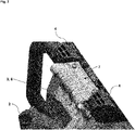
- a possible attachment of a fender is shown in 1 shown.
- the front handle is designed as a circumferential handle.
- circumferential is not an unclear concept for the person skilled in the art, because the person skilled in the art knows that front handles in the field of machine tools usually run around the housing or the main body of the device. In other words, such front handles at least partially enclose the housing or the main body of the machine tool, which on the one hand enables the machine tool to be guided stably by the user. On the other hand, the machine is effectively protected against mechanical damage, for example against impacts or when falling, by the preferably circumferential front handle.
- a lower section of the protective plate with the feet is arranged in the area of an underside of the front handle, this underside preferably coinciding with an underside of the housing or the main body of the machine tool.
- a possible attachment of a protective plate to the machine tool is discussed in 2 shown.
- the tabs at least partially form the lower section of the mudguard.
- the front handle is usually held in the left hand.
- the rear handle is usually held in the right hand. It can preferably be designed as a C- or D-shaped handle.
- the power tool includes both a first, front handle and a second, rear handle.
- the rear handle preferably comprises operating means for the machine tool, for example in order to switch the machine tool on or off or to change operating parameters.
- the lugs of the protective plate can be arranged on the side of the protective plate in order to facilitate the mounting of the feet on the machine tool.
- the tabs are therefore preferably also referred to as lateral tabs.
- the feet can be preassembled on the fender, thereby forming an assembly that can be attached to the machine tool in one work step. This can make it much easier to attach the feet to the machine tool.
- the assembly represents a second aspect of the present invention and can preferably also be referred to as a pre-assembly assembly in the context of the invention.
- the feet can include slots into which the tabs of the fender can be inserted.
- the devices to support the safe standing of the machine tool can have slots for receiving the tabs of the protective plate, with the feet being able to be pushed laterally onto the tabs of the protective plate.
- the lugs can be provided with a bead for a better hold of the pre-assembled feet, so that a pretension can be applied by undersizing the slot width on the foot.
- the lateral fixation of the feet is preferably effected by a raised and circumferential counter-contour on the housing part. This can be done by a higher rib on the housing of the machine tool running around the edge and encompassing the base. As a result, the base is held securely and stably on the housing of the machine tool in both spatial directions.
- the machine tool has a raised counter-contour for fastening the feet to the protective plate.
- the machine tool includes a housing, with the counter-contour for fastening the feet being formed by a peripheral raised wall on the housing of the machine tool.
- the feet can be fixed by a relatively large pressing surface on the housing of the machine tool.
- the large bearing surface of the feet on a base is preferably also favored by the specific spatial shape of the feet.
- Preferred embodiments of the feet are shown in the figures.
- An embodiment of the feet with a trapezoidal base area is particularly preferred. Due to the comparatively large contact surface, the risk of cracks forming in the material of the base can be significantly reduced, so that the rubber bases provided for the machine tool are particularly robust and durable.
- the invention makes it possible to dispense with the use of additional fastening screws and washers for fastening the feet.
- the assembly step for attaching the feet to the housing of the machine tool can be omitted, since this is advantageously done by assembling the pre-assembled assembly made up of protective plate and feet.
- the mudguard has an L-shape with a front section and a lower section. Furthermore, it may be preferred that the front section and the lower section enclose an angle with one another which is in a range from 70 to 110 degrees, preferably between 80 and 100 degrees and most preferably between 85 and 95 degrees.
- the area between the front and the lower section of the mudguard is formed by a curve of the material.
- a transition between the front section and the lower section of the mudguard can be designed as a circular arc surface, with the circular arc surface being able to be used as a rolling surface.
- the transition between the front and the lower section of the mudguard is designed as a generous circular arc surface, which includes an angle of 70 to 110 degrees, preferably 80 and 100 degrees and most preferably an angular range of 85 and 95 degrees.
- the angle subtended by the circular arc surface corresponds to the angle subtended by the front portion and a lower portion of the fender.
- the arcuate surface can advantageously serve on the one hand as a rolling surface on the ground when the cutting disk is inserted, and on the other hand as a scraping edge during the actual cutting process.
- the front area of the protective plate is arranged on a front side of the housing or the main body of the machine tool when the protective plate or the assembly is attached to the machine tool. It is also preferred within the meaning of the invention that the lower area of the protective plate is arranged on an underside of the housing or the main body of the machine tool when the protective plate or the assembly is attached to the machine tool. The corresponding arrangement when mounted on the machine tool is in the 1 and 2 to see.
- the preferably L-shaped design of the protective plate enables the protective plate or the assembly to be attached to the machine tool in a stable manner. Furthermore, the internal, sensitive components of the machine tool, which are preferably present in its main body, can be optimally protected against flying sparks, such as can occur when cutting steel, by the preferably L-shaped design of the protective plate.
- the lower section of the mudguard has at least one bead to increase the flexural rigidity of the mudguard.
- the bead advantageously serves to improve the flexural rigidity of the lower section of the fender, particularly in the area of the brackets onto which the feet are pushed.
- the at least one bead is used to increase the prestress on the feet so that the feet do not fall off the tabs after pre-assembly.
- the front section of the mudguard can also have at least one bead to increase the flexural rigidity of the mudguard.
- the front section of the mudguard has three beads to improve the flexural rigidity of the mudguard. These three beads are shown in the figures.
- the feet have an essentially trapezoidal base area. Possible specific shapes for the feet are shown, for example, in the figures.
- the use of feet, preferably symmetrical are designed to their central axis, allows the use of identical parts, whereby the production and processing of the feet can be simplified.
- the machine tool has two feet, one foot each being able to be pushed onto one side of the tab of the fender. As a result, good stability of the machine tool can advantageously be achieved when it is parked on its feet.
- the invention in a further aspect, relates to an assembly for the rapid assembly of a protective plate and feet on a machine tool.
- the assembly comprises a mudguard and feet, wherein the feet comprise an elastic material and can be (pre)assembled to the tabs of the mudguard.
- the assembly is advantageously a separate component that can also be sold individually.
- the subassembly can be preassembled in the sense that the feet are attached to the lugs of the mudguard and this unit can then be attached to the machine tool as a separate subassembly.
- An essential advantage of the invention is that the assembly of the feet on the machine tool can be made much easier and faster by pre-assembling the feet on the fender. It is preferred within the meaning of the invention that the proposed assembly can be obtained through this pre-assembly, which includes in particular the protective plate and the feet, and which is set up to be attached to the machine tool. It is particularly preferred within the meaning of the invention that the preassembled assembly is attached to a bottom side and a front side of the main body of the machine tool can be mounted.
- a front section of the protective plate is preferably mounted on the front of the machine tool, this front facing the tool of the machine tool, while a lower section of the protective plate, on which the feet are also arranged in the pre-assembled state, is mounted on an underside of the machine tool .
- FIG. 1 shows a preferred embodiment of the proposed machine tool 1.
- the in 1 The machine tool 1 shown has a front, circumferential handle and a rear handle. The handles enclose a main body of the machine tool 1 which is surrounded by a housing 11 . Furthermore, the machine tool 1 has a tool 2, in which 1 representative of the protective hood of the tool 2 is denoted by the reference numeral 2.
- the machine tool 1 shown represents a cut-off grinder which is preferably set up to make cuts in hard materials such as concrete and steel.
- the tool 2 of such a cut-off grinder 1 is usually disc-shaped and is referred to as a cut-off wheel.
- the front circumferential handle and the rear handle of the machine tool 1 preferably define the spatial directions “front” and “back” and “front” and “back”. It is preferred within the meaning of the invention that the main body of the machine tool 1 has a front side which is arranged in the area of the front, circumferential handle of the machine tool 1 . This front side of the machine tool main body 1 is preferably arranged to face the tool 2 of the machine tool 1 .
- the preassembled assembly 10 which in particular comprises a protective plate 3 and feet 4 .
- the pre-assembly of the assembly 10 consists in the fact that the feet 4 are pushed onto tabs 5 of the fender 3 so that they are held by the fender 3 .
- the feet 4 can have slots 8 which are designed in such a way that they can accommodate the lateral tabs 5 of the mudguard 3 .
- the preassembled subassembly 10 consisting of the protective plate 3 and the feet 4 can be attached to the machine tool 1 in a particularly simple and uncomplicated manner.
- the feet 4 are made of an elastic material, such as rubber, or include such an elastic material. Due to the elasticity of the material of the feet 4, the machine tool 1, which is provided with the assembly 10, has a secure and stable footing and can be placed on a surface in a particularly non-slip manner.
- the mudguard 3 has an L-shape with a front section 6 and a lower section 7, the front section 6 and the lower section 7 of the mudguard 3 forming a substantially right angle with one another. This angle can be 85 degrees, 90 degrees or 93 degrees, for example. It is preferred within the meaning of the invention that the front section 6 of the fender 3 in the assembled state on the front of the The main body of the machine tool 1 is arranged, while the lower section 7 of the protective plate 3 is arranged on an underside of the machine tool 1 in the assembled state.
- FIG. 2 shows a preferred embodiment of the underside of the proposed machine tool 1.
- the lower section 7 of the protective plate 3 can be seen in particular, it being this lower section 7 of the protective plate 3 in particular on which the tabs 5 for fastening the feet 4 are arranged. This is also used in particular in 3 shown.
- the protective plate 3 can be fastened to the machine tool 1 or its housing 11 with two fastening screws. In the lower left area of 2 the tool 2 of the machine tool 1 or its protective hood can be seen.
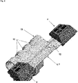
- the upper part of 3 shows the fender 3 with its components front portion 6, lower portion 7 and the tabs 5, which are preferably located on the lower portion 7 of the fender 3, preferably on the sides of the lower portion 7.
- the upper part of FIG 3 the fender 3 with the side tabs 5 for attaching the feet 4.
- the lower part of 3 shows the finished pre-assembled assembly 10, wherein the feet 4 are already attached to the tabs 5 of the mudguard 3.
- the feet 4 can have slots 8 with which the feet 4 can be pushed over the tabs 5 of the lower section 7 of the mudguard 3 .
- FIG. 4 shows a preferred embodiment of the feet 4 with their slots 8, in which the tabs 5 of the mudguard 3 can be inserted.
- figure 5 shows a preferred embodiment of the assembly 10 in the assembled state on the machine tool 1. You can see the fender 3 or the front section 6 and the lower section 7 of the fender 3, as well as the feet 4. Granted in particular figure 5 a look at a preferred embodiment of the underside of the proposed machine tool 1.
- the counter-contour 9 is preferably on the underside of the machine tool 1 before. It is preferred within the meaning of the invention that the counter-contour 9 is raised and set up for fastening the protective plate 3 of the machine tool 1 . Within the meaning of the invention, it is particularly preferred that the counter-contour 9 is formed by a circumferential raised wall on the housing 11 of the machine tool 1 . This wall advantageously ensures that the base 4 is guided laterally in the housing 11 .
- FIG. 7 shows a preferred embodiment of the feet 4, with which a particularly safe and stable position of the machine tool 1 can be achieved. Furthermore, the anti-slip properties of the machine tool 1 can be significantly improved by the feet 4 .
- a major advantage of the invention is that the assembly of the feet 4 on the machine tool 1 can be made considerably easier and faster by pre-assembling the feet 4 on the protective plate 3, with the pre-assembly of the feet 4 and protective plate 3 making the proposed assembly 10 can be obtained.
- FIG. 8 shows a preferred embodiment of the assembly 10 in the non-assembled state on the machine tool 1.
- the assembly 10, which in 8 is shown is preassembled in the sense that the feet 4 are mounted on the side tabs 5 of the mudguard 3 .
- the subassembly 10 obtained in this way is not mounted on the machine tool 1, which is why the corresponding state is referred to as “not mounted”.
Landscapes
- Engineering & Computer Science (AREA)
- Mechanical Engineering (AREA)
- Grinding-Machine Dressing And Accessory Apparatuses (AREA)
- Body Structure For Vehicles (AREA)
Priority Applications (5)
| Application Number | Priority Date | Filing Date | Title |
|---|---|---|---|
| EP20211901.2A EP4008466A1 (fr) | 2020-12-04 | 2020-12-04 | Machine-outil doté d'un outil en forme de disque et d'une tôle de protection destinée à la protection contre le vol d'étincelles |
| PCT/EP2021/081383 WO2022117308A1 (fr) | 2020-12-04 | 2021-11-11 | Outil motorisé avec outil en forme de disque et plaque protectrice pour protection contre les étincelles projetées |
| CN202180076926.7A CN116457127A (zh) | 2020-12-04 | 2021-11-11 | 具有圆盘状工具和用于防护飞散的火花的护板的动力工具 |
| EP21805979.8A EP4255658A1 (fr) | 2020-12-04 | 2021-11-11 | Outil motorisé avec outil en forme de disque et plaque protectrice pour protection contre les étincelles projetées |
| US18/038,484 US12459079B2 (en) | 2020-12-04 | 2021-11-11 | Power tool having a disk-shaped tool and a guard plate for protecting against flying sparks |
Applications Claiming Priority (1)
| Application Number | Priority Date | Filing Date | Title |
|---|---|---|---|
| EP20211901.2A EP4008466A1 (fr) | 2020-12-04 | 2020-12-04 | Machine-outil doté d'un outil en forme de disque et d'une tôle de protection destinée à la protection contre le vol d'étincelles |
Publications (1)
| Publication Number | Publication Date |
|---|---|
| EP4008466A1 true EP4008466A1 (fr) | 2022-06-08 |
Family
ID=73726666
Family Applications (2)
| Application Number | Title | Priority Date | Filing Date |
|---|---|---|---|
| EP20211901.2A Withdrawn EP4008466A1 (fr) | 2020-12-04 | 2020-12-04 | Machine-outil doté d'un outil en forme de disque et d'une tôle de protection destinée à la protection contre le vol d'étincelles |
| EP21805979.8A Pending EP4255658A1 (fr) | 2020-12-04 | 2021-11-11 | Outil motorisé avec outil en forme de disque et plaque protectrice pour protection contre les étincelles projetées |
Family Applications After (1)
| Application Number | Title | Priority Date | Filing Date |
|---|---|---|---|
| EP21805979.8A Pending EP4255658A1 (fr) | 2020-12-04 | 2021-11-11 | Outil motorisé avec outil en forme de disque et plaque protectrice pour protection contre les étincelles projetées |
Country Status (4)
| Country | Link |
|---|---|
| US (1) | US12459079B2 (fr) |
| EP (2) | EP4008466A1 (fr) |
| CN (1) | CN116457127A (fr) |
| WO (1) | WO2022117308A1 (fr) |
Families Citing this family (3)
| Publication number | Priority date | Publication date | Assignee | Title |
|---|---|---|---|---|
| EP4008491A1 (fr) * | 2020-12-04 | 2022-06-08 | Hilti Aktiengesellschaft | Machine-outil doté d'une première poignée, d'une seconde poignée et d'un corps principal |
| EP4008475A1 (fr) | 2020-12-04 | 2022-06-08 | Hilti Aktiengesellschaft | Machine-outil dotée d'une poignée avant et d'une unité de régulation |
| EP4008466A1 (fr) | 2020-12-04 | 2022-06-08 | Hilti Aktiengesellschaft | Machine-outil doté d'un outil en forme de disque et d'une tôle de protection destinée à la protection contre le vol d'étincelles |
Citations (6)
| Publication number | Priority date | Publication date | Assignee | Title |
|---|---|---|---|---|
| US5890292A (en) * | 1996-07-25 | 1999-04-06 | Andreas Stihl | Portable hand-guided work apparatus having a tool guard |
| WO2007069946A1 (fr) * | 2005-12-14 | 2007-06-21 | Husqvarna Ab | Machine de travail portative |
| US20100288907A1 (en) * | 2009-05-12 | 2010-11-18 | Makita Corporation | Floor plate |
| US20110214657A1 (en) * | 2010-03-03 | 2011-09-08 | Makita Corporation | Engine-driven cutter |
| US20130180116A1 (en) * | 2012-01-18 | 2013-07-18 | Hitachi Koki Co., Ltd | Portable cutting machine |
| EP3173187A1 (fr) * | 2015-11-25 | 2017-05-31 | HILTI Aktiengesellschaft | Tronçonneuse portative manuelle |
Family Cites Families (30)
| Publication number | Priority date | Publication date | Assignee | Title |
|---|---|---|---|---|
| US3971906A (en) | 1974-11-01 | 1976-07-27 | Lucerne Products, Inc. | Trigger-lock control |
| DE4334933C2 (de) | 1993-10-13 | 1997-02-20 | Fraunhofer Ges Forschung | Verfahren und Vorrichtung zum zwangsweisen Abschalten von handgeführten Arbeitsmitteln |
| US5577600A (en) | 1995-11-21 | 1996-11-26 | Emerson Electric Co. | Switch lock-out device for power tool |
| US6591826B1 (en) | 2000-06-06 | 2003-07-15 | Aktiebolaget Electrolux (Publ) | Device on a portable cutting or sawing machine |
| AUPS001902A0 (en) | 2002-01-18 | 2002-02-07 | Ramsay, George Stephen | Improvement to power tools and trigger handles therefore |
| US6623342B1 (en) | 2002-03-02 | 2003-09-23 | Pearl Abrasive Company | Support accessory for power hand tool |
| DE10259520A1 (de) | 2002-12-19 | 2004-07-01 | Robert Bosch Gmbh | Elektrohandwerkzeugmaschine |
| US6812425B1 (en) | 2003-11-24 | 2004-11-02 | Defond Components Limited | Locking trigger switch mechanism |
| ATE524262T1 (de) * | 2003-12-09 | 2011-09-15 | Husqvarna Ab | Tragbare arbeitsmaschine |
| US6989503B2 (en) | 2004-03-22 | 2006-01-24 | Defond Components Limited | Power tool trigger assembly |
| DE202004007699U1 (de) * | 2004-05-13 | 2004-07-15 | Dolmar Gmbh | Fußeinheit für Trennschleifer |
| DE102005002126A1 (de) * | 2005-01-17 | 2006-07-20 | Andreas Stihl Ag & Co. Kg | Wasserversorgung eines handgeführten Arbeitsgerätes |
| AU2008246247B2 (en) | 2006-04-26 | 2011-11-03 | Demain Technology Pty Ltd | A handle assembly for a power tool |
| WO2012070989A1 (fr) * | 2010-11-23 | 2012-05-31 | Husqvarna Ab | Dispositif de coupe thermique |
| CA2876579C (fr) * | 2012-06-12 | 2015-11-17 | Husqvarna Ab | Systeme de coupe electrique |
| DE102013012746A1 (de) * | 2013-07-31 | 2015-02-05 | Andreas Stihl Ag & Co. Kg | Handgeführtes Arbeitsgerät |
| DE102014208980A1 (de) | 2014-01-27 | 2015-07-30 | Robert Bosch Gmbh | Werkzeugmaschinenvorrichtung |
| DE102014009144A1 (de) | 2014-06-20 | 2015-12-24 | Andreas Stihl Ag & Co. Kg | Handgeführtes Arbeitsgerät |
| TWI593908B (zh) | 2015-10-16 | 2017-08-01 | 力山工業股份有限公司 | 開關鍵安全裝置 |
| US10818450B2 (en) | 2017-06-14 | 2020-10-27 | Black & Decker Inc. | Paddle switch |
| US11964356B2 (en) | 2018-04-05 | 2024-04-23 | Makita Corporation | Hand-held tool |
| CN113165138B (zh) | 2018-11-30 | 2023-08-29 | 工机控股株式会社 | 作业机 |
| WO2021107827A1 (fr) * | 2019-11-25 | 2021-06-03 | Husqvarna Ab | Outil de travail portatif alimenté électriquement |
| DE112020006394T5 (de) * | 2019-12-27 | 2022-10-13 | Koki Holdings Co., Ltd. | Werkzeug |
| DE202020002472U1 (de) | 2020-06-04 | 2020-07-06 | Jenn Feng New Energy Co., Ltd. | Auslöser-Schalteinrichtung eines angetriebenen Werkzeugs zum Verhindern eines unbeabsichtigten Auslösevorgangs |
| EP4147824A4 (fr) * | 2020-06-15 | 2023-12-06 | Globe (Jiangsu) Co., Ltd. | Dispositif de coupe électrique |
| EP4008466A1 (fr) | 2020-12-04 | 2022-06-08 | Hilti Aktiengesellschaft | Machine-outil doté d'un outil en forme de disque et d'une tôle de protection destinée à la protection contre le vol d'étincelles |
| EP4008476A1 (fr) | 2020-12-04 | 2022-06-08 | Hilti Aktiengesellschaft | Procédé de protection d'un utilisateur lors de l'utilisation d'une machine-outil ainsi que machine-outil |
| EP4008475A1 (fr) | 2020-12-04 | 2022-06-08 | Hilti Aktiengesellschaft | Machine-outil dotée d'une poignée avant et d'une unité de régulation |
| EP4008492A1 (fr) | 2020-12-04 | 2022-06-08 | Hilti Aktiengesellschaft | Poignée pour machine-outil, machine-outil et son procédé de mise sous tension, de mise hors tension et de verrouillage |
-
2020
- 2020-12-04 EP EP20211901.2A patent/EP4008466A1/fr not_active Withdrawn
-
2021
- 2021-11-11 WO PCT/EP2021/081383 patent/WO2022117308A1/fr not_active Ceased
- 2021-11-11 US US18/038,484 patent/US12459079B2/en active Active
- 2021-11-11 EP EP21805979.8A patent/EP4255658A1/fr active Pending
- 2021-11-11 CN CN202180076926.7A patent/CN116457127A/zh active Pending
Patent Citations (6)
| Publication number | Priority date | Publication date | Assignee | Title |
|---|---|---|---|---|
| US5890292A (en) * | 1996-07-25 | 1999-04-06 | Andreas Stihl | Portable hand-guided work apparatus having a tool guard |
| WO2007069946A1 (fr) * | 2005-12-14 | 2007-06-21 | Husqvarna Ab | Machine de travail portative |
| US20100288907A1 (en) * | 2009-05-12 | 2010-11-18 | Makita Corporation | Floor plate |
| US20110214657A1 (en) * | 2010-03-03 | 2011-09-08 | Makita Corporation | Engine-driven cutter |
| US20130180116A1 (en) * | 2012-01-18 | 2013-07-18 | Hitachi Koki Co., Ltd | Portable cutting machine |
| EP3173187A1 (fr) * | 2015-11-25 | 2017-05-31 | HILTI Aktiengesellschaft | Tronçonneuse portative manuelle |
Also Published As
| Publication number | Publication date |
|---|---|
| US12459079B2 (en) | 2025-11-04 |
| EP4255658A1 (fr) | 2023-10-11 |
| CN116457127A (zh) | 2023-07-18 |
| US20240009802A1 (en) | 2024-01-11 |
| WO2022117308A1 (fr) | 2022-06-09 |
Similar Documents
| Publication | Publication Date | Title |
|---|---|---|
| EP4255658A1 (fr) | Outil motorisé avec outil en forme de disque et plaque protectrice pour protection contre les étincelles projetées | |
| DE102016213259B4 (de) | Schnellbefestigungssystem für rotierende Mähmesser | |
| EP3792008B1 (fr) | Appareil de travail portatif doté d'un outil | |
| EP1074341B1 (fr) | Carter de protection contre la poussière pour outil de meulage de surfaces | |
| EP0518165B1 (fr) | Superstructure de véhicule | |
| DE10350627B4 (de) | Turbinenrotor- und Schaufelanordnung, Vorspannfedersegment und zugehöriges Verfahren für Dampfturbinenschaufeln der Reaktionsbauart | |
| DE112013000305B3 (de) | Schutzvorrichtung für Bedienungsperson, mit Schutzvorrichtung versehene Kabine für Arbeitsmaschine und Arbeitsmaschine | |
| EP1777047A1 (fr) | Couvercle de protection | |
| CH659563A5 (de) | Vorrichtung zum maehen von erntegut. | |
| WO2003043785A1 (fr) | Machine-outil a main comportant au moins une poignee | |
| EP1642674A1 (fr) | Capot pour outil motorisé | |
| EP3053717B1 (fr) | Appareil de travail | |
| DE3208821A1 (de) | Einspannvorrichtung fuer ein drehbares schneid- bzw. saegeblatt sowie kreissaege | |
| DE202014010215U1 (de) | Kantenschneidsystem für einen Verdichter | |
| DE3914679A1 (de) | Kettensaegenanordnung | |
| DE19816164B4 (de) | Schneidkopf | |
| DE102004063723B4 (de) | Schutzschild für ein Schneidwerkzeug eines Freischneiders | |
| DE1578940A1 (de) | Vorrichtung zum Schaerfen der Laufkante eines Skis | |
| DE60210218T2 (de) | Gehrungssäge | |
| DE19521067A1 (de) | Mähscheibe mit Klingenbefestigung für Rotationsmähwerk | |
| DE102006041671A1 (de) | Schutzhaube einer Handwerkzeugmaschine | |
| DE4224665C2 (de) | Scherblattträger einer Heckenschere | |
| DE602004003726T2 (de) | Klemmvorrichtung und Verfahren zum Klemmen eines Teils mit solchen Klemmvorrichtungen | |
| DE112023004579T5 (de) | Kettensäge | |
| DE2233336A1 (de) | Befestigungsanordnung zum verbinden eines messers mit einer maeher-messerwelle |
Legal Events
| Date | Code | Title | Description |
|---|---|---|---|
| PUAI | Public reference made under article 153(3) epc to a published international application that has entered the european phase |
Free format text: ORIGINAL CODE: 0009012 |
|
| STAA | Information on the status of an ep patent application or granted ep patent |
Free format text: STATUS: THE APPLICATION HAS BEEN PUBLISHED |
|
| AK | Designated contracting states |
Kind code of ref document: A1 Designated state(s): AL AT BE BG CH CY CZ DE DK EE ES FI FR GB GR HR HU IE IS IT LI LT LU LV MC MK MT NL NO PL PT RO RS SE SI SK SM TR |
|
| STAA | Information on the status of an ep patent application or granted ep patent |
Free format text: STATUS: THE APPLICATION IS DEEMED TO BE WITHDRAWN |
|
| 18D | Application deemed to be withdrawn |
Effective date: 20221209 |