EP4008481A1 - Dispositif de serrage - Google Patents
Dispositif de serrage Download PDFInfo
- Publication number
- EP4008481A1 EP4008481A1 EP21211952.3A EP21211952A EP4008481A1 EP 4008481 A1 EP4008481 A1 EP 4008481A1 EP 21211952 A EP21211952 A EP 21211952A EP 4008481 A1 EP4008481 A1 EP 4008481A1
- Authority
- EP
- European Patent Office
- Prior art keywords
- clamping
- bearing section
- lifting
- relative
- clamping device
- Prior art date
- Legal status (The legal status is an assumption and is not a legal conclusion. Google has not performed a legal analysis and makes no representation as to the accuracy of the status listed.)
- Granted
Links
Images


Classifications
-
- B—PERFORMING OPERATIONS; TRANSPORTING
- B25—HAND TOOLS; PORTABLE POWER-DRIVEN TOOLS; MANIPULATORS
- B25B—TOOLS OR BENCH DEVICES NOT OTHERWISE PROVIDED FOR, FOR FASTENING, CONNECTING, DISENGAGING, OR HOLDING
- B25B5/00—Clamps
- B25B5/06—Arrangements for positively actuating jaws
- B25B5/061—Arrangements for positively actuating jaws with fluid drive
-
- B—PERFORMING OPERATIONS; TRANSPORTING
- B25—HAND TOOLS; PORTABLE POWER-DRIVEN TOOLS; MANIPULATORS
- B25B—TOOLS OR BENCH DEVICES NOT OTHERWISE PROVIDED FOR, FOR FASTENING, CONNECTING, DISENGAGING, OR HOLDING
- B25B5/00—Clamps
- B25B5/06—Arrangements for positively actuating jaws
- B25B5/067—C-clamps
-
- B—PERFORMING OPERATIONS; TRANSPORTING
- B25—HAND TOOLS; PORTABLE POWER-DRIVEN TOOLS; MANIPULATORS
- B25B—TOOLS OR BENCH DEVICES NOT OTHERWISE PROVIDED FOR, FOR FASTENING, CONNECTING, DISENGAGING, OR HOLDING
- B25B5/00—Clamps
- B25B5/16—Details, e.g. jaws, jaw attachments
Definitions
- the invention relates to a clamping device according to the preamble of claim 1.
- Corresponding clamping devices which are used in particular as vertical clamps for clamping workpieces, are known from the prior art, for example from DE 101 08 134 A1 or EP 3 009 226 B1 or WO 2016/071351 A1 .
- All of these clamping devices have a first and a second clamping element with a first and second clamping surface, respectively, it being possible for a workpiece to be clamped between the clamping surfaces.
- the workpiece has to be released from the clamping device, for example if it has to be re-clamped to machine another side of the workpiece. Since this process is usually carried out manually, a possibility must be created to carry out this re-clamping as simply as possible, with the re-fixing of the workpiece also generally having to be carried out manually.
- the entire clamping device is usually also moved from one location on which the clamping device is stored to another location. After the displacement, the clamping device must be returned to a state in which the workpiece can be clamped. It is important that the support level on the lower clamping element of the workpiece assumes the position it was in before reclamping.
- the object of the present invention is therefore to specify a tensioning device of the type mentioned at the outset that makes this possible.
- the clamping device according to the invention which is in particular a vertical clamp, is used to clamp workpieces of all kinds, in particular those made of wood or wood substitutes, plastics, metals and the like.
- the clamping device has a first clamping element with a first clamping surface and a second clamping element with a second clamping surface facing the first clamping surface.
- the first clamping element and the second clamping element can be moved relative to one another in a clamping direction for clamping or releasing a workpiece between the clamping surfaces via a drive device.
- the clamping device according to the invention has a bearing section, on which the second clamping element is attached with play and, in particular in the clamping direction, is guided displaceably within the play.
- the tensioning device comprises a lifting device which is designed to move the second clamping element relative to the bearing section within the clearance, in particular parallel to the clamping direction.
- This relative displacement of the second clamping element relative to the bearing section within a predetermined play allows the support plane of the second clamping element to be displaced. If the clamping between the clamping device and the workpiece is released before this shift, the workpiece can be re-clamped relatively quickly and the clamping device can be moved just as quickly. The support plane of the clamping device can then be returned to the initial state at the new position.
- the bearing section is attached to a base.
- the lower part comprises a cylinder with a piston connected to the first clamping element, the piston being displaceably guided in the cylinder parallel to the clamping direction.
- the actual clamping process of the workpiece can be implemented using this piston/cylinder arrangement.
- the cylinder can be set up in such a way that the first clamping surface is moved towards the second clamping surface by evacuating the cylinder.
- the cylinder can also be actuated by pressurization.
- the second clamping element and the bearing section are designed such that they cannot rotate relative to one another. This ensures that rotation of the second clamping element when re-clamping leaves no traces of friction on the workpiece.
- a lifting element which is rotatably mounted relative to the bearing section, is arranged between the bearing section and the clamping element. About this lifting element, the clamping element is raised within the game. The actuation of the clamping element, i. H. its adjustment in the lifting direction is thus brought about indirectly via the movement of the lifting element.
- the lifting element at least a first Lifting surface and at least one second lifting surface is arranged on the bearing section. These lifting surfaces are in engagement with one another, so that they run off one another when the lifting element rotates. This is preferably done in such a way that the lifting surfaces interact with one another during relative rotation of the bearing section and the lifting element in such a way that the second clamping surface is lifted or lowered relative to the first clamping surface.
- the lifting surfaces have ramps that rise and/or fall relative to the plane of rotation of the bearing section and the lifting element.
- the element interacting with the ramp on the respective other component is guided over the inclined surface, in particular inclined surface, of the ramp, so that the relative distance between the two components rotated relative to one another changes.
- the clamping device according to the invention has a releasable safety device, in particular an anti-rotation device, which is designed to prevent a relative movement, in particular relative rotation, between the bearing section in the locked state and to prevent lifting element.
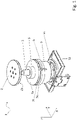
- the clamping device 1 shown has a first, upper clamping element 2 with a first clamping surface 2a and a second, lower clamping element 7f with a second clamping surface 7a. These can be moved relative to one another via a piston 3 .
- the piston 3 is displaceably mounted in a cylinder 9 parallel to the vertical direction Z or generally in a lifting direction.
- the entire tensioning device 1 can be arranged as a unit, for example via a foot part 11, on a substructure arrangement 12 (not shown otherwise) and can also be moved thereon.
- the piston 3 is guided in a bearing section 5 .
- the second clamping element 7f is rotationally fixed or at least not substantially rotatable, but is mounted with play at least in the vertical direction Z.
- a lifting element 7e is arranged below the second clamping element 7f , which here - as in particular the sectional drawings of figures 2 and 3 show - between the second clamping element 7f and the bearing portion 5 is arranged.
- the lifting element 7e can be rotated about an axis of rotation parallel to the vertical axis Z relative to the second clamping element 7f.
- a safety 6 is designed in the example shown in the form of an anti-rotation as a lever.
- the second clamping element 7f is attached to the bearing section 5 and is fixed via at least one securing section, which preferably has the shape of a threaded pin 7d and which engages in a recess 5a of the bearing section 5 .
- the recess 5a has vertical play. This play allows a slight movement of the clamping element 7f with its clamping surface 7a in direction Z. It is also advantageous if the clamping element 7f is otherwise non-rotatably mounted relative to the bearing section 5 .
- the threaded pin 7d is pressed against the upper wall, viewed in the vertical direction, of the recess 5a, which can be an annular recess, for example.
- corresponding lifting means 7b and 5b are arranged both on the lifting element 7e and on the bearing section 5 .
- these can be ramps, shafts, cams or similar surfaces that slide over one another during a relative rotational movement between the lifting element 7e and the bearing section 5 .
- the lifting element 7e is raised or lowered. in figure 2 In the state shown, raised areas 5b and 7b of bearing section 5 and lifting element 7e face each other, so that the maximum stroke is set here.
- the reference numeral 9 designates a cylinder to which the bearing section 5 is fastened and in the cubic capacity 10 of which the piston 3 can be moved back and forth.
Landscapes
- Engineering & Computer Science (AREA)
- Mechanical Engineering (AREA)
- Jigs For Machine Tools (AREA)
Applications Claiming Priority (1)
| Application Number | Priority Date | Filing Date | Title |
|---|---|---|---|
| DE102020132391.3A DE102020132391A1 (de) | 2020-12-07 | 2020-12-07 | Spanneinrichtung |
Publications (3)
| Publication Number | Publication Date |
|---|---|
| EP4008481A1 true EP4008481A1 (fr) | 2022-06-08 |
| EP4008481C0 EP4008481C0 (fr) | 2024-02-07 |
| EP4008481B1 EP4008481B1 (fr) | 2024-02-07 |
Family
ID=78821054
Family Applications (1)
| Application Number | Title | Priority Date | Filing Date |
|---|---|---|---|
| EP21211952.3A Active EP4008481B1 (fr) | 2020-12-07 | 2021-12-02 | Dispositif de serrage |
Country Status (3)
| Country | Link |
|---|---|
| EP (1) | EP4008481B1 (fr) |
| DE (1) | DE102020132391A1 (fr) |
| PL (1) | PL4008481T3 (fr) |
Cited By (1)
| Publication number | Priority date | Publication date | Assignee | Title |
|---|---|---|---|---|
| CN118204730A (zh) * | 2022-12-16 | 2024-06-18 | 重庆科勒发动机有限公司 | 一种顶升回转装置 |
Citations (4)
| Publication number | Priority date | Publication date | Assignee | Title |
|---|---|---|---|---|
| DE10108134A1 (de) | 2000-02-22 | 2001-09-06 | Biesse Spa | Maschine zum Bearbeiten von Tafeln aus Holz oder dergleichen |
| DE102008011804A1 (de) * | 2007-03-02 | 2008-10-30 | Grandi Progetti S.R.L. | Maschine zum Bearbeiten von Holzteilen oder ähnlichen Teilen |
| WO2016071351A1 (fr) | 2014-11-03 | 2016-05-12 | Homag Holzbearbeitungssysteme Gmbh | Dispositif de serrage |
| EP3009226B1 (fr) | 2014-10-13 | 2017-01-11 | Biesse S.p.A. | Dispositif de serrage pour plaque sur une surface de travail d'un appareil de traitement, en particulier pour plaques de traitement de petites dimensions, notamment en verre ou en pierre et en bois |
Family Cites Families (3)
| Publication number | Priority date | Publication date | Assignee | Title |
|---|---|---|---|---|
| DE19938851B4 (de) | 1999-08-17 | 2005-04-07 | Gustav Weeke Maschinenbau Gmbh | Vorrichtung zum Spannen von Werkstücken |
| EP1990135B1 (fr) | 2007-05-11 | 2009-11-04 | Homag Holzbearbeitungssysteme AG | Dispositif de serrage de pièce |
| DE102014211433A1 (de) | 2014-06-16 | 2015-12-17 | Schaeffler Technologies AG & Co. KG | Linearaktuator |
-
2020
- 2020-12-07 DE DE102020132391.3A patent/DE102020132391A1/de not_active Withdrawn
-
2021
- 2021-12-02 EP EP21211952.3A patent/EP4008481B1/fr active Active
- 2021-12-02 PL PL21211952.3T patent/PL4008481T3/pl unknown
Patent Citations (4)
| Publication number | Priority date | Publication date | Assignee | Title |
|---|---|---|---|---|
| DE10108134A1 (de) | 2000-02-22 | 2001-09-06 | Biesse Spa | Maschine zum Bearbeiten von Tafeln aus Holz oder dergleichen |
| DE102008011804A1 (de) * | 2007-03-02 | 2008-10-30 | Grandi Progetti S.R.L. | Maschine zum Bearbeiten von Holzteilen oder ähnlichen Teilen |
| EP3009226B1 (fr) | 2014-10-13 | 2017-01-11 | Biesse S.p.A. | Dispositif de serrage pour plaque sur une surface de travail d'un appareil de traitement, en particulier pour plaques de traitement de petites dimensions, notamment en verre ou en pierre et en bois |
| WO2016071351A1 (fr) | 2014-11-03 | 2016-05-12 | Homag Holzbearbeitungssysteme Gmbh | Dispositif de serrage |
Cited By (1)
| Publication number | Priority date | Publication date | Assignee | Title |
|---|---|---|---|---|
| CN118204730A (zh) * | 2022-12-16 | 2024-06-18 | 重庆科勒发动机有限公司 | 一种顶升回转装置 |
Also Published As
| Publication number | Publication date |
|---|---|
| EP4008481C0 (fr) | 2024-02-07 |
| PL4008481T3 (pl) | 2024-06-10 |
| DE102020132391A1 (de) | 2022-06-09 |
| EP4008481B1 (fr) | 2024-02-07 |
Similar Documents
| Publication | Publication Date | Title |
|---|---|---|
| DE3531824A1 (de) | Lenkrolle | |
| DE2630281C2 (de) | Kopfstütze für Fahrzeugsitze, insbesondere Kraftfahrzeugsitze | |
| EP2255693B1 (fr) | Mécanisme de verrouillage | |
| EP3941310B1 (fr) | Mécanisme de coulissement et de pivotement d'une tablette d'un meuble ou d'un appareil électroménager, et meuble ou appareil électroménager | |
| DE2229556A1 (de) | Geschirrspulmaschine mit hoheneinstell barem Geschirrschub | |
| EP3468413A1 (fr) | Mobilier pourvu de tiroir et de plaque d'extension | |
| EP4008481B1 (fr) | Dispositif de serrage | |
| EP1336709A1 (fr) | Dispositif de verrouillage pour empêcher l'ouverture simultanée de tiroirs superposés | |
| DE19812490C2 (de) | Einrichtung zur lösbaren Befestigung eines Sitzes, insbesondere Fahrzeugsitzes, an einer längsverlaufenden Schiene | |
| DE1452821B1 (de) | Abkantpresse mit Einstellvorrichtung | |
| EP0622175B1 (fr) | Presse à commande manuelle | |
| EP0408671B1 (fr) | Mecanisme a manivelle pour un toit ouvrant et coulissant de vehicule a moteur | |
| DE202017100035U1 (de) | Möbel mit Auszug | |
| EP2890627B1 (fr) | Dispositif de verrouillage | |
| EP1696764A1 (fr) | Dispositif de freinage pour tables de travail | |
| EP3089890B1 (fr) | Recouvrement d'un compartiment à bagages d`un véhicule automobile | |
| DE2347900A1 (de) | Vorrichtung zum blockieren von raedern von verfahrbaren gegenstaenden, wie krankenhausbetten, bahren, tische u. dgl | |
| EP1661490A1 (fr) | Table régable en hauteur à pieds croisés | |
| DE19816248C1 (de) | Lehneneinstellbeschlag für einen Fahrzeugsitz | |
| DE202016103040U1 (de) | Möbel mit Auszug | |
| DE19614708C1 (de) | Anordnung zur Verlängerung des Gabelblattes von Gabelzinken | |
| DE10211211B4 (de) | Höhenverstellbares Säulenelement für ein Lastfahrzeug | |
| DE2615074A1 (de) | Hebebuehne, insbesondere zweisaeulenhebebuehne, fuer kraftfahrzeuge | |
| DE102004038998B4 (de) | Komponente für ein Fahrzeug, insbesondere für ein Kraftfahrzeug | |
| DE102018100272A1 (de) | Tischanordnung für ein fahrzeug und verfahren zur betätigung der tischanordnung |
Legal Events
| Date | Code | Title | Description |
|---|---|---|---|
| PUAI | Public reference made under article 153(3) epc to a published international application that has entered the european phase |
Free format text: ORIGINAL CODE: 0009012 |
|
| STAA | Information on the status of an ep patent application or granted ep patent |
Free format text: STATUS: THE APPLICATION HAS BEEN PUBLISHED |
|
| AK | Designated contracting states |
Kind code of ref document: A1 Designated state(s): AL AT BE BG CH CY CZ DE DK EE ES FI FR GB GR HR HU IE IS IT LI LT LU LV MC MK MT NL NO PL PT RO RS SE SI SK SM TR |
|
| STAA | Information on the status of an ep patent application or granted ep patent |
Free format text: STATUS: REQUEST FOR EXAMINATION WAS MADE |
|
| 17P | Request for examination filed |
Effective date: 20221206 |
|
| RBV | Designated contracting states (corrected) |
Designated state(s): AL AT BE BG CH CY CZ DE DK EE ES FI FR GB GR HR HU IE IS IT LI LT LU LV MC MK MT NL NO PL PT RO RS SE SI SK SM TR |
|
| GRAP | Despatch of communication of intention to grant a patent |
Free format text: ORIGINAL CODE: EPIDOSNIGR1 |
|
| STAA | Information on the status of an ep patent application or granted ep patent |
Free format text: STATUS: GRANT OF PATENT IS INTENDED |
|
| INTG | Intention to grant announced |
Effective date: 20230824 |
|
| GRAS | Grant fee paid |
Free format text: ORIGINAL CODE: EPIDOSNIGR3 |
|
| GRAA | (expected) grant |
Free format text: ORIGINAL CODE: 0009210 |
|
| STAA | Information on the status of an ep patent application or granted ep patent |
Free format text: STATUS: THE PATENT HAS BEEN GRANTED |
|
| AK | Designated contracting states |
Kind code of ref document: B1 Designated state(s): AL AT BE BG CH CY CZ DE DK EE ES FI FR GB GR HR HU IE IS IT LI LT LU LV MC MK MT NL NO PL PT RO RS SE SI SK SM TR |
|
| REG | Reference to a national code |
Ref country code: GB Ref legal event code: FG4D Free format text: NOT ENGLISH |
|
| REG | Reference to a national code |
Ref country code: CH Ref legal event code: EP |
|
| REG | Reference to a national code |
Ref country code: IE Ref legal event code: FG4D Free format text: LANGUAGE OF EP DOCUMENT: GERMAN |
|
| REG | Reference to a national code |
Ref country code: DE Ref legal event code: R096 Ref document number: 502021002637 Country of ref document: DE |
|
| U01 | Request for unitary effect filed |
Effective date: 20240212 |
|
| U07 | Unitary effect registered |
Designated state(s): AT BE BG DE DK EE FI FR IT LT LU LV MT NL PT SE SI Effective date: 20240221 |
|
| PG25 | Lapsed in a contracting state [announced via postgrant information from national office to epo] |
Ref country code: IS Free format text: LAPSE BECAUSE OF FAILURE TO SUBMIT A TRANSLATION OF THE DESCRIPTION OR TO PAY THE FEE WITHIN THE PRESCRIBED TIME-LIMIT Effective date: 20240607 |
|
| PG25 | Lapsed in a contracting state [announced via postgrant information from national office to epo] |
Ref country code: GR Free format text: LAPSE BECAUSE OF FAILURE TO SUBMIT A TRANSLATION OF THE DESCRIPTION OR TO PAY THE FEE WITHIN THE PRESCRIBED TIME-LIMIT Effective date: 20240508 |
|
| PG25 | Lapsed in a contracting state [announced via postgrant information from national office to epo] |
Ref country code: HR Free format text: LAPSE BECAUSE OF FAILURE TO SUBMIT A TRANSLATION OF THE DESCRIPTION OR TO PAY THE FEE WITHIN THE PRESCRIBED TIME-LIMIT Effective date: 20240207 Ref country code: RS Free format text: LAPSE BECAUSE OF FAILURE TO SUBMIT A TRANSLATION OF THE DESCRIPTION OR TO PAY THE FEE WITHIN THE PRESCRIBED TIME-LIMIT Effective date: 20240507 |
|
| PG25 | Lapsed in a contracting state [announced via postgrant information from national office to epo] |
Ref country code: ES Free format text: LAPSE BECAUSE OF FAILURE TO SUBMIT A TRANSLATION OF THE DESCRIPTION OR TO PAY THE FEE WITHIN THE PRESCRIBED TIME-LIMIT Effective date: 20240207 |
|
| PG25 | Lapsed in a contracting state [announced via postgrant information from national office to epo] |
Ref country code: RS Free format text: LAPSE BECAUSE OF FAILURE TO SUBMIT A TRANSLATION OF THE DESCRIPTION OR TO PAY THE FEE WITHIN THE PRESCRIBED TIME-LIMIT Effective date: 20240507 Ref country code: NO Free format text: LAPSE BECAUSE OF FAILURE TO SUBMIT A TRANSLATION OF THE DESCRIPTION OR TO PAY THE FEE WITHIN THE PRESCRIBED TIME-LIMIT Effective date: 20240507 Ref country code: IS Free format text: LAPSE BECAUSE OF FAILURE TO SUBMIT A TRANSLATION OF THE DESCRIPTION OR TO PAY THE FEE WITHIN THE PRESCRIBED TIME-LIMIT Effective date: 20240607 Ref country code: HR Free format text: LAPSE BECAUSE OF FAILURE TO SUBMIT A TRANSLATION OF THE DESCRIPTION OR TO PAY THE FEE WITHIN THE PRESCRIBED TIME-LIMIT Effective date: 20240207 Ref country code: GR Free format text: LAPSE BECAUSE OF FAILURE TO SUBMIT A TRANSLATION OF THE DESCRIPTION OR TO PAY THE FEE WITHIN THE PRESCRIBED TIME-LIMIT Effective date: 20240508 Ref country code: ES Free format text: LAPSE BECAUSE OF FAILURE TO SUBMIT A TRANSLATION OF THE DESCRIPTION OR TO PAY THE FEE WITHIN THE PRESCRIBED TIME-LIMIT Effective date: 20240207 |
|
| PG25 | Lapsed in a contracting state [announced via postgrant information from national office to epo] |
Ref country code: SM Free format text: LAPSE BECAUSE OF FAILURE TO SUBMIT A TRANSLATION OF THE DESCRIPTION OR TO PAY THE FEE WITHIN THE PRESCRIBED TIME-LIMIT Effective date: 20240207 |
|
| PG25 | Lapsed in a contracting state [announced via postgrant information from national office to epo] |
Ref country code: CZ Free format text: LAPSE BECAUSE OF FAILURE TO SUBMIT A TRANSLATION OF THE DESCRIPTION OR TO PAY THE FEE WITHIN THE PRESCRIBED TIME-LIMIT Effective date: 20240207 |
|
| PG25 | Lapsed in a contracting state [announced via postgrant information from national office to epo] |
Ref country code: SK Free format text: LAPSE BECAUSE OF FAILURE TO SUBMIT A TRANSLATION OF THE DESCRIPTION OR TO PAY THE FEE WITHIN THE PRESCRIBED TIME-LIMIT Effective date: 20240207 |
|
| PG25 | Lapsed in a contracting state [announced via postgrant information from national office to epo] |
Ref country code: SM Free format text: LAPSE BECAUSE OF FAILURE TO SUBMIT A TRANSLATION OF THE DESCRIPTION OR TO PAY THE FEE WITHIN THE PRESCRIBED TIME-LIMIT Effective date: 20240207 Ref country code: SK Free format text: LAPSE BECAUSE OF FAILURE TO SUBMIT A TRANSLATION OF THE DESCRIPTION OR TO PAY THE FEE WITHIN THE PRESCRIBED TIME-LIMIT Effective date: 20240207 Ref country code: RO Free format text: LAPSE BECAUSE OF FAILURE TO SUBMIT A TRANSLATION OF THE DESCRIPTION OR TO PAY THE FEE WITHIN THE PRESCRIBED TIME-LIMIT Effective date: 20240207 Ref country code: CZ Free format text: LAPSE BECAUSE OF FAILURE TO SUBMIT A TRANSLATION OF THE DESCRIPTION OR TO PAY THE FEE WITHIN THE PRESCRIBED TIME-LIMIT Effective date: 20240207 |
|
| REG | Reference to a national code |
Ref country code: DE Ref legal event code: R097 Ref document number: 502021002637 Country of ref document: DE |
|
| PLBE | No opposition filed within time limit |
Free format text: ORIGINAL CODE: 0009261 |
|
| STAA | Information on the status of an ep patent application or granted ep patent |
Free format text: STATUS: NO OPPOSITION FILED WITHIN TIME LIMIT |
|
| 26N | No opposition filed |
Effective date: 20241108 |
|
| U20 | Renewal fee for the european patent with unitary effect paid |
Year of fee payment: 4 Effective date: 20241223 |
|
| PG25 | Lapsed in a contracting state [announced via postgrant information from national office to epo] |
Ref country code: MC Free format text: LAPSE BECAUSE OF FAILURE TO SUBMIT A TRANSLATION OF THE DESCRIPTION OR TO PAY THE FEE WITHIN THE PRESCRIBED TIME-LIMIT Effective date: 20240207 |
|
| REG | Reference to a national code |
Ref country code: CH Ref legal event code: PL |
|
| PG25 | Lapsed in a contracting state [announced via postgrant information from national office to epo] |
Ref country code: CH Free format text: LAPSE BECAUSE OF NON-PAYMENT OF DUE FEES Effective date: 20241231 |
|
| PG25 | Lapsed in a contracting state [announced via postgrant information from national office to epo] |
Ref country code: IE Free format text: LAPSE BECAUSE OF NON-PAYMENT OF DUE FEES Effective date: 20241202 |
|
| U20 | Renewal fee for the european patent with unitary effect paid |
Year of fee payment: 5 Effective date: 20251216 |
|
| PGFP | Annual fee paid to national office [announced via postgrant information from national office to epo] |
Ref country code: PL Payment date: 20251126 Year of fee payment: 5 |
|
| PG25 | Lapsed in a contracting state [announced via postgrant information from national office to epo] |
Ref country code: CY Free format text: LAPSE BECAUSE OF FAILURE TO SUBMIT A TRANSLATION OF THE DESCRIPTION OR TO PAY THE FEE WITHIN THE PRESCRIBED TIME-LIMIT; INVALID AB INITIO Effective date: 20211202 |