EP4008486A1 - Machine-outil à deux moteurs - Google Patents
Machine-outil à deux moteurs Download PDFInfo
- Publication number
- EP4008486A1 EP4008486A1 EP20211791.7A EP20211791A EP4008486A1 EP 4008486 A1 EP4008486 A1 EP 4008486A1 EP 20211791 A EP20211791 A EP 20211791A EP 4008486 A1 EP4008486 A1 EP 4008486A1
- Authority
- EP
- European Patent Office
- Prior art keywords
- tool
- axis
- drive device
- drive
- rotation
- Prior art date
- Legal status (The legal status is an assumption and is not a legal conclusion. Google has not performed a legal analysis and makes no representation as to the accuracy of the status listed.)
- Withdrawn
Links
Images

Classifications
-
- B—PERFORMING OPERATIONS; TRANSPORTING
- B25—HAND TOOLS; PORTABLE POWER-DRIVEN TOOLS; MANIPULATORS
- B25D—PERCUSSIVE TOOLS
- B25D11/00—Portable percussive tools with electromotor or other motor drive
- B25D11/06—Means for driving the impulse member
- B25D11/12—Means for driving the impulse member comprising a crank mechanism
- B25D11/125—Means for driving the impulse member comprising a crank mechanism with a fluid cushion between the crank drive and the striking body
-
- B—PERFORMING OPERATIONS; TRANSPORTING
- B25—HAND TOOLS; PORTABLE POWER-DRIVEN TOOLS; MANIPULATORS
- B25D—PERCUSSIVE TOOLS
- B25D16/00—Portable percussive machines with superimposed rotation, the rotational movement of the output shaft of a motor being modified to generate axial impacts on the tool bit
-
- B—PERFORMING OPERATIONS; TRANSPORTING
- B25—HAND TOOLS; PORTABLE POWER-DRIVEN TOOLS; MANIPULATORS
- B25D—PERCUSSIVE TOOLS
- B25D2211/00—Details of portable percussive tools with electromotor or other motor drive
- B25D2211/003—Crossed drill and motor spindles
-
- B—PERFORMING OPERATIONS; TRANSPORTING
- B25—HAND TOOLS; PORTABLE POWER-DRIVEN TOOLS; MANIPULATORS
- B25D—PERCUSSIVE TOOLS
- B25D2250/00—General details of portable percussive tools; Components used in portable percussive tools
- B25D2250/245—Spatial arrangement of components of the tool relative to each other
-
- B—PERFORMING OPERATIONS; TRANSPORTING
- B25—HAND TOOLS; PORTABLE POWER-DRIVEN TOOLS; MANIPULATORS
- B25D—PERCUSSIVE TOOLS
- B25D2250/00—General details of portable percussive tools; Components used in portable percussive tools
- B25D2250/275—Tools having at least two similar components
- B25D2250/281—Double motors
Definitions
- the invention relates to a machine tool, in particular a rotary hammer, containing a housing, a tool holder for receiving and holding a tool, an impact mechanism device for generating and transmitting impact impulses to the tool, and a rotary device for generating and transmitting torque to the tool, with a Percussion device extending working axis is provided.
- a hammer drill is a working machine for drilling holes in mineral materials such as stone or concrete.
- the hammer drill has, among other things, a rotary drive and a percussion mechanism.
- a drilling tool held by the rotary hammer is rotated about a rotary axis (also called the working axis) with the aid of the rotary drive.
- the impact mechanism is used to generate impact impulses on the drilling tool along the working or impact axis. Due to the impact impulses, the cutting edge of the drilling tool wears down the material to be processed.
- These hammer drills known from the prior art usually contain only an electric motor as a drive, which drives both the rotary drive and the percussion mechanism via a relatively complex gear.
- the object of the present invention is therefore to provide a machine tool, in particular a hammer drill, in order to solve the problem mentioned above.
- a machine tool in particular a hammer drill, containing a housing, a tool holder for receiving and holding a tool, an impact mechanism for generating and transmitting impact impulses to the tool, and a rotary device for generating and transmitting a torque to the tool, with a working axis running through the impact mechanism being provided.
- the machine tool contains a first drive device with a first axis of rotation for driving the rotary device and a second drive device with a second axis of rotation for driving the percussion mechanism, the first and second drive devices being arranged in relation to one another in the housing such that the first axis of rotation of the first drive device is in is arranged at a first angle to the second axis of rotation of the second drive device and at a second angle to the working axis.
- both the first angle and the second angle can be designed as an acute angle, with the first angle being able to have a value of 50° to 80° and the second angle being able to have a value of 10° to 30° .
- the installation space inside the housing can be used particularly effectively and the machine tool can be designed to be compact overall.
- the first drive device may contain a first transmission device and for the second drive device to contain a second transmission device.
- a gear wheel in the form of a bevel gear mechanism may be included for connecting the first drive device to the rotary device.
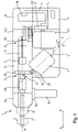
- FIG 1 a machine tool 1 according to the invention is shown in an exemplary configuration as a hammer drill.
- the machine tool 1 designed as a hammer drill has a housing 2, a tool holder 3 and an energy supply device 4.
- the case basically includes a front end 2a, a rear end 2b, a left side, a right side, a top and a bottom.
- the energy supply device 4 and a first handle 5 are positioned at the rear end 2b of the housing 2 as can be seen.
- the first handle 5 is used for holding and guiding the machine tool 1 by a user and can also be referred to as the main handle.
- the first handle 5 contains an activation switch 5a for activating the machine tool 1.
- the activation switch 5a is connected via lines L to a control device 6 in such a way that the machine tool 1 is switched from a deactivation mode to an activation mode when the activation switch 5a moves in the direction of the arrow B becomes.
- the machine tool 1 is in turn switched from the activation mode to the deactivation mode when the activation switch 5a is moved in the direction of the arrow A with the aid of a spring which is not shown in the figures.
- the control device 6 is in turn connected to the energy supply device 4 via lines L for controlling and regulating various functions.
- the energy supply device 4 serves to supply the machine tool 1 with electrical energy.
- the energy supply device 4 is designed in the form of an accumulator (also referred to as an accumulator or battery) that can be detached from the machine tool 1 .
- the energy supply device 4 can also be designed as a power cable for the releasable connection of the machine tool 1 to a power network (i.e. socket).
- the tool holder 3 is positioned at the front end 2a of the housing 2 .
- the tool holder 3 is used to receive and hold a tool 7.
- the tool 7 is designed as a drill.
- the tool 7 can also be designed as a chisel.
- a second handle 8 is positioned at the front end 2a of the housing 2 of the machine tool 1 .
- the second handle 8 is used in addition to the first handle 5 for holding and guiding the machine tool 1 and can also be referred to as an auxiliary handle.
- the second handle 8 can be removed from the machine tool 1 with the aid of a connecting device 8a.
- the interior of the housing 2 essentially contains the control device 6 , an impact mechanism device 9 , a rotary device 10 , a first drive device 11 , a first gear device 12 , a second drive device 13 and a second gear device 14 .
- control device 6 serves, among other things, to control and regulate functions of the energy supply device 4 .
- control device 6 controls and regulates various functions individually, such as the respective speed of the first drive device 11 and the second drive device 13.
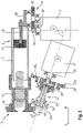
- the percussion mechanism 9 is used to generate and transmit impact impulses to the tool 7 and essentially contains a guide tube 15, a die 16 and an exciter piston 17. As shown in the figures, the die 16 and the exciter piston 17 are inside the guide tube 15 positioned. The die 16 is located in the direction of the arrow A in front of the exciter piston 17.
- the guide tube 15 is non-rotatably connected to the tool holder 3, so that when the guide tube 15 rotates about the working axis N in the direction of rotation R, the tool holder 3 and the one in the tool holder 3 also rotate held tool 7 also rotates about the working axis N in the direction of rotation R.
- the rotary device 10 is used to generate and transmit a torque via the guide tube 15 and the tool holder 3 to the tool 7 designed as a drill 18 designed as a bevel gear. Furthermore, the rotary device 10 contains a pinion 19 (also called a drive gear) corresponding to the bevel gear 18 . As further described below, pinion 19 serves to drive bevel gear 18. Pinion 19 can be positioned either directly on end 20 of the rotor or on end 21a of a drive shaft 21 connected to end 20 of the rotor be.
- Both the first and the second drive device 11, 13 are each designed in the form of an electric motor and each contain essentially a stator and a stator Stator drivable rotor. As in the figures 2 and 3 recognizable, one end 20 of the rotor protrudes from the stator.
- a first axis of rotation S runs through the center of the rotor of the first drive device 11. The rotor of the first drive device 11 is rotated about the first axis of rotation S.
- a second axis of rotation T passes through the center of the rotor of the second drive means 13. The rotor of the second drive means 13 is rotated about the second axis of rotation T .
- the first drive device 11 designed as an electric motor is connected to the rotary device 10 .
- the second drive device 13 embodied as an electric motor is in turn connected to the striking mechanism device 9 .
- the first drive device 11 is connected to the rotary device 10 via a drive shaft 21, cf. figure 2 .
- the drive shaft 21 is fastened in a rotationally fixed manner to the end 20 of the rotor protruding from the stator. The rotational movement of the rotor is transmitted to the drive shaft 21.
- the pinion 19 is attached at the end 21a of the drive shaft 21, which is opposite the first drive device 11, the pinion 19 is attached.
- the pinion 19 is arranged relative to the bevel gear 18 in such a way that a rotational movement of the rotor of the first drive device 11 is transmitted via the pinion 19 to the bevel gear 18, the guide tube 15, the tool holder 3 and finally to the tool 7.
- the teeth of the pinion 19 engage the teeth of the bevel gear 18 and drive it.
- the direct or immediate connection of the first drive device 11 transmits the rotational speed of the rotor and the pinion 19 directly to the bevel gear 18.
- the bevel gear 18 and the pinion 19 are designed in a specific transmission ratio to one another.
- the transmission ratio is determined by the number of teeth on the pinion 19 and the number of teeth on the bevel gear 18 or by the ratio of the number of teeth on the pinion 19 to the number of teeth on the bevel gear 18.
- the ratio of the number of teeth of the pinion 19 to the number of teeth of the bevel gear 18 is 0.2 (ie zero point 2 in words).
- the number of teeth of the pinion 19 is identical to the number of teeth of the bevel gear 18.
- the ratio of the number of teeth of the pinion 19 to the number of teeth of the bevel gear 18 can be between 2 and 0.1.
- the ratio of the number of teeth of the pinion 18 to the bevel gear 19 is between 0.1 and 0.5.
- the length L of the first drive device 11, the drive shaft 21 and the pinion 19 is 100 mm. According to alternative embodiments, the length L can be between 50 and 300 mm and in particular between 80 and 200 mm.
- the first drive device 11 is connected to the rotary device 10 via a first transmission device 12, cf. figure 3 .
- the first transmission device 12 essentially contains a ring gear 22, a first and second planetary gear 23a, 23b, a planetary gear carrier 24, a transmission ball bearing 25 and the drive shaft 21.
- the ring gear 22 is fixed to the housing 2 of the machine tool 1. Both the first planetary gear 23a and the second planetary gear 23b are positioned in the ring gear 22 .
- the pinion 19, which is positioned at the end 20 of the rotor of the first drive device 11, drives the two planet gears 23a, 23b.
- the planetary gear carrier 24 is caused to rotate by the two planetary gears 23a, 23b.
- the planetary gear carrier 24 is in turn connected to the drive shaft 21, so that the drive shaft 21 is also caused to rotate.
- the gear ball bearing 25 is used to support the drive shaft 21.
- another pinion 19 is positioned at the end of the drive shaft 21 which is opposite the planet gear carrier 24, another pinion 19 is positioned. This pinion 19 transmits the rotary movement of the drive shaft 21 to the bevel gear 18 and rotates the guide tube 15 about the working axis N.
- the second drive device 13 is connected to the impact mechanism device 9 via a second gear device 14 in such a way that a torque that can be generated in the first drive device 11 is transmitted to the exciter piston 17 .
- the second transmission device 14 contains a pinion 19', a gear wheel 27, an eccentric 28 and a connecting rod 29.
- the connecting rod 29 can also be referred to as a connecting rod, connecting rod or connecting rod.
- the pinion 19' is fixed in a torque-proof manner to the end 20' of the rotor of the second drive device 13, which end protrudes from the stator of the second drive device 13.
- the gear 27 of the second transmission device 14 is positioned relative to the pinion 19' such that the gear 27 is driven by the pinion 19'.
- the eccentric 28 is in turn arranged in relation to the gear wheel 27 in such a way that the gear wheel 27 drives the eccentric 28 .
- the connecting rod 29 connects the exciter piston 17 to the eccentric 28 so that the movement of the eccentric 28 is transmitted to the exciter piston 17 .
- the exciter piston 17 moves by the eccentric 28 along the guide tube 15 in the direction of arrow A or B.
- the movement of the exciter piston 17 in the guide tube 15 drives the die 16 via an air spring present between the exciter piston 17 and the die 16.
- the die 16 in turn transmits the impact impulses to the tool holder 3 and the tool 7.
- the first and second drive devices 11, 13 are arranged relative to one another in the housing 2 such that the first axis of rotation S of the first drive device 11 is arranged at a first angle ⁇ to the second axis of rotation T of the second drive device 13 and at a second angle ⁇ to the working axis N.
- the value of the first angle ⁇ is 60° and the value of the second angle ⁇ is 20°.
- the first angle ⁇ can have a value of 50° to 80° and the second value ⁇ between 10° and 30°.
- the first axis of rotation S lies on one level with the second axis of rotation T.
- the first axis of rotation S and the second axis of rotation T can also lie on different planes.
Landscapes
- Engineering & Computer Science (AREA)
- Mechanical Engineering (AREA)
- Percussive Tools And Related Accessories (AREA)
- Drilling And Boring (AREA)
Priority Applications (5)
| Application Number | Priority Date | Filing Date | Title |
|---|---|---|---|
| EP20211791.7A EP4008486A1 (fr) | 2020-12-04 | 2020-12-04 | Machine-outil à deux moteurs |
| EP21805995.4A EP4255683A1 (fr) | 2020-12-04 | 2021-11-16 | Machine-outil à deux moteurs |
| PCT/EP2021/081831 WO2022117332A1 (fr) | 2020-12-04 | 2021-11-16 | Machine-outil à deux moteurs |
| US18/039,558 US12172279B2 (en) | 2020-12-04 | 2021-11-16 | Power tool having two motors |
| CN202180073648.XA CN116507454B (zh) | 2020-12-04 | 2021-11-16 | 具有两个马达的动力工具 |
Applications Claiming Priority (1)
| Application Number | Priority Date | Filing Date | Title |
|---|---|---|---|
| EP20211791.7A EP4008486A1 (fr) | 2020-12-04 | 2020-12-04 | Machine-outil à deux moteurs |
Publications (1)
| Publication Number | Publication Date |
|---|---|
| EP4008486A1 true EP4008486A1 (fr) | 2022-06-08 |
Family
ID=73726596
Family Applications (2)
| Application Number | Title | Priority Date | Filing Date |
|---|---|---|---|
| EP20211791.7A Withdrawn EP4008486A1 (fr) | 2020-12-04 | 2020-12-04 | Machine-outil à deux moteurs |
| EP21805995.4A Pending EP4255683A1 (fr) | 2020-12-04 | 2021-11-16 | Machine-outil à deux moteurs |
Family Applications After (1)
| Application Number | Title | Priority Date | Filing Date |
|---|---|---|---|
| EP21805995.4A Pending EP4255683A1 (fr) | 2020-12-04 | 2021-11-16 | Machine-outil à deux moteurs |
Country Status (4)
| Country | Link |
|---|---|
| US (1) | US12172279B2 (fr) |
| EP (2) | EP4008486A1 (fr) |
| CN (1) | CN116507454B (fr) |
| WO (1) | WO2022117332A1 (fr) |
Cited By (1)
| Publication number | Priority date | Publication date | Assignee | Title |
|---|---|---|---|---|
| EP4420815A1 (fr) * | 2023-02-24 | 2024-08-28 | Hilti Aktiengesellschaft | Marteau perforateur et procédé de travail associé pour former un trou de forage contre-découpé |
Families Citing this family (2)
| Publication number | Priority date | Publication date | Assignee | Title |
|---|---|---|---|---|
| US11819968B2 (en) | 2021-01-19 | 2023-11-21 | Milwaukee Electric Tool Corporation | Rotary power tool |
| EP4438232A1 (fr) * | 2023-03-29 | 2024-10-02 | Hilti Aktiengesellschaft | Marteau perforateur à entraînement multiple |
Citations (7)
| Publication number | Priority date | Publication date | Assignee | Title |
|---|---|---|---|---|
| DE2343661A1 (de) * | 1973-08-30 | 1975-03-06 | Bosch Gmbh Robert | Bohrhammer |
| FR2625931A1 (fr) * | 1988-01-14 | 1989-07-21 | Peugeot Outillage Elect | Machine electrique a main pour percage et percussion |
| EP0345896A2 (fr) * | 1988-06-07 | 1989-12-13 | Skil Europe B.V. | Dispositif pour l'entraînement d'un outil de forage et/ou à percussion |
| DE102005062861A1 (de) * | 2005-12-29 | 2007-07-05 | Robert Bosch Gmbh | Handwerkzeugmaschine, insbesondere Bohr- und/oder Meißelhammer |
| DE102008054458A1 (de) * | 2008-12-10 | 2010-06-17 | Robert Bosch Gmbh | Handwerkzeugmaschine |
| WO2012084316A1 (fr) * | 2010-12-21 | 2012-06-28 | Robert Bosch Gmbh | Outil électrique portatif |
| CN106335031B (zh) * | 2015-07-15 | 2020-06-23 | 苏州宝时得电动工具有限公司 | 电锤 |
Family Cites Families (3)
| Publication number | Priority date | Publication date | Assignee | Title |
|---|---|---|---|---|
| AT372639B (de) * | 1980-11-06 | 1983-10-25 | Hilti Ag | Schlagbohrmaschine |
| GB0428210D0 (en) * | 2004-12-23 | 2005-01-26 | Black & Decker Inc | Mode change mechanism |
| US11819968B2 (en) * | 2021-01-19 | 2023-11-21 | Milwaukee Electric Tool Corporation | Rotary power tool |
-
2020
- 2020-12-04 EP EP20211791.7A patent/EP4008486A1/fr not_active Withdrawn
-
2021
- 2021-11-16 CN CN202180073648.XA patent/CN116507454B/zh active Active
- 2021-11-16 US US18/039,558 patent/US12172279B2/en active Active
- 2021-11-16 EP EP21805995.4A patent/EP4255683A1/fr active Pending
- 2021-11-16 WO PCT/EP2021/081831 patent/WO2022117332A1/fr not_active Ceased
Patent Citations (7)
| Publication number | Priority date | Publication date | Assignee | Title |
|---|---|---|---|---|
| DE2343661A1 (de) * | 1973-08-30 | 1975-03-06 | Bosch Gmbh Robert | Bohrhammer |
| FR2625931A1 (fr) * | 1988-01-14 | 1989-07-21 | Peugeot Outillage Elect | Machine electrique a main pour percage et percussion |
| EP0345896A2 (fr) * | 1988-06-07 | 1989-12-13 | Skil Europe B.V. | Dispositif pour l'entraînement d'un outil de forage et/ou à percussion |
| DE102005062861A1 (de) * | 2005-12-29 | 2007-07-05 | Robert Bosch Gmbh | Handwerkzeugmaschine, insbesondere Bohr- und/oder Meißelhammer |
| DE102008054458A1 (de) * | 2008-12-10 | 2010-06-17 | Robert Bosch Gmbh | Handwerkzeugmaschine |
| WO2012084316A1 (fr) * | 2010-12-21 | 2012-06-28 | Robert Bosch Gmbh | Outil électrique portatif |
| CN106335031B (zh) * | 2015-07-15 | 2020-06-23 | 苏州宝时得电动工具有限公司 | 电锤 |
Cited By (1)
| Publication number | Priority date | Publication date | Assignee | Title |
|---|---|---|---|---|
| EP4420815A1 (fr) * | 2023-02-24 | 2024-08-28 | Hilti Aktiengesellschaft | Marteau perforateur et procédé de travail associé pour former un trou de forage contre-découpé |
Also Published As
| Publication number | Publication date |
|---|---|
| US12172279B2 (en) | 2024-12-24 |
| WO2022117332A1 (fr) | 2022-06-09 |
| CN116507454A (zh) | 2023-07-28 |
| US20240009822A1 (en) | 2024-01-11 |
| CN116507454B (zh) | 2025-10-28 |
| EP4255683A1 (fr) | 2023-10-11 |
Similar Documents
| Publication | Publication Date | Title |
|---|---|---|
| EP4255683A1 (fr) | Machine-outil à deux moteurs | |
| DE2136523A1 (de) | Elektrobohrhammer | |
| EP2364817A2 (fr) | Dispositif de marteau perforateur | |
| EP2212062B1 (fr) | Machine-outil à main | |
| EP3053708B1 (fr) | Dispositif auxiliaire | |
| DE3142740A1 (de) | Schlagbohrmaschine | |
| EP3880406A1 (fr) | Machine-outil portative | |
| EP4008488B1 (fr) | Dispositif de machine-outil à main | |
| DE4019894A1 (de) | Elektrohandwerkzeug | |
| EP2234769A1 (fr) | Machine-outil dotée d'un dispositif de transmission comportant au moins un arbre intermédiaire logé de façon rotative | |
| EP0408985A2 (fr) | Outil électrique à main | |
| EP3481590A1 (fr) | Système de machine-outil portative | |
| EP0419866A2 (fr) | Marteau de forage | |
| DE2212217A1 (de) | Schlagbohrgerät | |
| DE69803817T2 (de) | Bohrhammer | |
| DE102014101827A1 (de) | Bohrmaschine und Bohrwerkzeug hierfür | |
| WO2013057180A1 (fr) | Système additionnel et entraînement d'outil comprenant un tel système additionnel | |
| EP3789161A1 (fr) | Machine-outil manuelle | |
| EP3943226A1 (fr) | Machine de perçage | |
| EP2104594B1 (fr) | Machine-outil portative | |
| DE202018105582U1 (de) | Elektrohammer | |
| DE102012215458A1 (de) | Werkzeugmaschine | |
| DE102009028633A1 (de) | Vorrichtung für eine Handwerkzeugmaschine und Handwerkzeugmaschine | |
| DE3503921C2 (fr) | ||
| EP3854532A1 (fr) | Machine-outil, outil et système de machine-outil à un certain rapport de vitesse de rotation et de puissance de percussion |
Legal Events
| Date | Code | Title | Description |
|---|---|---|---|
| PUAI | Public reference made under article 153(3) epc to a published international application that has entered the european phase |
Free format text: ORIGINAL CODE: 0009012 |
|
| STAA | Information on the status of an ep patent application or granted ep patent |
Free format text: STATUS: THE APPLICATION HAS BEEN PUBLISHED |
|
| AK | Designated contracting states |
Kind code of ref document: A1 Designated state(s): AL AT BE BG CH CY CZ DE DK EE ES FI FR GB GR HR HU IE IS IT LI LT LU LV MC MK MT NL NO PL PT RO RS SE SI SK SM TR |
|
| STAA | Information on the status of an ep patent application or granted ep patent |
Free format text: STATUS: THE APPLICATION IS DEEMED TO BE WITHDRAWN |
|
| 18D | Application deemed to be withdrawn |
Effective date: 20221209 |