EP4008488B1 - Handwerkzeugmaschinenvorrichtung - Google Patents
Handwerkzeugmaschinenvorrichtung Download PDFInfo
- Publication number
- EP4008488B1 EP4008488B1 EP21216030.3A EP21216030A EP4008488B1 EP 4008488 B1 EP4008488 B1 EP 4008488B1 EP 21216030 A EP21216030 A EP 21216030A EP 4008488 B1 EP4008488 B1 EP 4008488B1
- Authority
- EP
- European Patent Office
- Prior art keywords
- intermediate shaft
- bearing
- power tool
- tool device
- hand
- Prior art date
- Legal status (The legal status is an assumption and is not a legal conclusion. Google has not performed a legal analysis and makes no representation as to the accuracy of the status listed.)
- Active
Links
Images




Classifications
-
- B—PERFORMING OPERATIONS; TRANSPORTING
- B25—HAND TOOLS; PORTABLE POWER-DRIVEN TOOLS; MANIPULATORS
- B25F—COMBINATION OR MULTI-PURPOSE TOOLS NOT OTHERWISE PROVIDED FOR; DETAILS OR COMPONENTS OF PORTABLE POWER-DRIVEN TOOLS NOT PARTICULARLY RELATED TO THE OPERATIONS PERFORMED AND NOT OTHERWISE PROVIDED FOR
- B25F5/00—Details or components of portable power-driven tools not particularly related to the operations performed and not otherwise provided for
- B25F5/001—Gearings, speed selectors, clutches or the like specially adapted for rotary tools
-
- B—PERFORMING OPERATIONS; TRANSPORTING
- B25—HAND TOOLS; PORTABLE POWER-DRIVEN TOOLS; MANIPULATORS
- B25B—TOOLS OR BENCH DEVICES NOT OTHERWISE PROVIDED FOR, FOR FASTENING, CONNECTING, DISENGAGING, OR HOLDING
- B25B21/00—Portable power-driven screw or nut setting or loosening tools; Attachments for drilling apparatus serving the same purpose
-
- B—PERFORMING OPERATIONS; TRANSPORTING
- B25—HAND TOOLS; PORTABLE POWER-DRIVEN TOOLS; MANIPULATORS
- B25B—TOOLS OR BENCH DEVICES NOT OTHERWISE PROVIDED FOR, FOR FASTENING, CONNECTING, DISENGAGING, OR HOLDING
- B25B21/00—Portable power-driven screw or nut setting or loosening tools; Attachments for drilling apparatus serving the same purpose
- B25B21/02—Portable power-driven screw or nut setting or loosening tools; Attachments for drilling apparatus serving the same purpose with means for imparting impact to screwdriver blade or nut socket
-
- B—PERFORMING OPERATIONS; TRANSPORTING
- B25—HAND TOOLS; PORTABLE POWER-DRIVEN TOOLS; MANIPULATORS
- B25F—COMBINATION OR MULTI-PURPOSE TOOLS NOT OTHERWISE PROVIDED FOR; DETAILS OR COMPONENTS OF PORTABLE POWER-DRIVEN TOOLS NOT PARTICULARLY RELATED TO THE OPERATIONS PERFORMED AND NOT OTHERWISE PROVIDED FOR
- B25F5/00—Details or components of portable power-driven tools not particularly related to the operations performed and not otherwise provided for
-
- B—PERFORMING OPERATIONS; TRANSPORTING
- B25—HAND TOOLS; PORTABLE POWER-DRIVEN TOOLS; MANIPULATORS
- B25F—COMBINATION OR MULTI-PURPOSE TOOLS NOT OTHERWISE PROVIDED FOR; DETAILS OR COMPONENTS OF PORTABLE POWER-DRIVEN TOOLS NOT PARTICULARLY RELATED TO THE OPERATIONS PERFORMED AND NOT OTHERWISE PROVIDED FOR
- B25F5/00—Details or components of portable power-driven tools not particularly related to the operations performed and not otherwise provided for
- B25F5/02—Construction of casings, bodies or handles
Definitions
- a hand-held power tool device has already been proposed with a drive unit which has at least one drive shaft, and with at least one rotary impact mechanism which has at least one intermediate shaft which is at least substantially aligned with the drive shaft, and with at least one bearing for supporting the drive shaft.
- a power-driven working machine which comprises an outer casing, a drive motor arranged in the casing for driving a tool part, a drive shaft extending from the drive motor, an electrical element for operating the drive motor, a heat radiation block fixedly attached to the drive motor, a power control element fixedly attached to the heat radiation block for controlling a rotational speed of the drive motor, and a device which prevents rotational movement of the drive motor in engagement with the heat radiation block with the outer casing.
- JP 2005 066804 A discloses a rotary impact wrench with a motor, a housing in which the motor is arranged, a planetary gear and a rotary impact mechanism.
- the invention is based on a hand-held power tool device with a drive unit which has at least one drive shaft, and with at least one rotary impact mechanism which has at least one intermediate shaft which is aligned at least substantially in alignment with the drive shaft, and with at least one bearing for supporting the drive shaft.
- the bearing is arranged at least partially in a plane intersecting the intermediate shaft, which plane runs at least substantially perpendicular to the intermediate shaft.
- a "handheld power tool device” is to be understood as at least one part, in particular a subassembly, of a handheld power tool.
- the handheld power tool device can also comprise the entire handheld power tool.
- the handheld power tool can be designed as any desired, preferably electrical, machine, but advantageously as a rotary impact wrench.
- a "drive unit” is to be understood as a unit that is intended, in particular,
- a “bearing” is understood to mean, in particular, a radial bearing designed to rotatably support the drive shaft relative to the intermediate shaft.
- the term "essentially perpendicular” is intended here to define, in particular, an orientation of a direction relative to a reference direction, wherein the direction and the reference direction, particularly viewed in a plane, enclose an angle of 90° and the angle has a maximum deviation of, in particular, less than 8°, advantageously less than 5°, and particularly advantageously less than 2°.
- the plane intersects both the intermediate shaft and the drive shaft at least essentially perpendicularly.
- the drive shaft is preferably mounted at least partially within the intermediate shaft.
- Such a configuration makes it possible to provide a generic handheld power tool device with advantageous design properties.
- an advantageously compact design in particular an advantageously short overall length, of the rotary impact mechanism can be achieved.
- the length of the handheld power tool device is, for example, a maximum of 200 mm, in particular a maximum of 160 mm, most particularly a maximum of 140 mm, and particularly preferably a maximum of 130 mm.
- the length of the handheld power tool device includes, in particular, the drive unit and the rotary impact mechanism, as well as a tool holder.
- the intermediate shaft have at least one receiving recess, which is provided for at least partially receiving the drive shaft.
- the receiving recess extends along a rotational axis of the intermediate shaft.
- the drive shaft protrudes at least partially into the intermediate shaft, in particular into the receiving recess of the intermediate shaft.
- the bearing can be designed as a plain bearing and/or a roller bearing.
- the bearing is at least partially designed as a roller bearing, for example, as a ball bearing, roller bearing, or needle bearing.
- the bearing is arranged at least partially, advantageously completely, within the recess. This allows for advantageously low-friction mounting of the drive shaft.
- an advantageously short overall length of the rotary impact mechanism can be achieved.
- the intermediate shaft have at least one sealing element receptacle.
- the sealing element receptacle is arranged directly at an insertion opening of the receiving recess of the intermediate shaft, which is provided for inserting a drive shaft into the intermediate shaft.
- the sealing element receptacle is provided in particular for at least partially receiving a sealing element, in particular a sealing ring and/or a shaft sealing ring.
- the intermediate shaft has at least one sealing element arranged in the sealing element receptacle.
- the sealing element is designed in particular as a shaft sealing ring, in particular as a radial shaft sealing ring.
- the sealing element is provided in particular for at least substantially sealing the rotary impact mechanism, in particular the planetary gear of the rotary impact mechanism, from its surroundings. In this way, an advantageously reliable sealing of the rotary impact mechanism can be achieved.
- a handheld power tool in particular a rotary impact wrench, with at least one handheld power tool device according to the invention is proposed.
- the handheld power tool can have an advantageously short overall length.
- the handheld power tool device according to the invention is not intended to be limited to the application and embodiment described above.
- the handheld power tool device according to the invention may have a number of individual elements, components, and units that differs from the number stated herein to fulfill a function described herein.
- FIG. 1 shows a handheld power tool 34a, which is designed as a rotary impact wrench, in a schematic partial sectional view.
- the handheld power tool 34a is designed as a cordless rotary impact wrench.
- the handheld power tool 34a comprises a handle 80, which extends perpendicular to a rotational axis 84a of a tool holder 86a of the handheld power tool 34a, which is provided for receiving an insert tool (not shown here).
- the handle 80a comprises a battery receptacle 90a on a side 88a facing away from the handheld power tool 34a.
- the battery receptacle 90a is intended to accommodate a battery unit 92a for supplying power to the handheld power tool 34a.
- the hand-held power tool 34a has a hand-held power tool device 10a with a drive unit 12a and a rotary impact mechanism 16a.
- Figure 2 shows the handheld power tool device 10 in a sectional view.
- the handheld power tool device 10a has a drive housing 72a and a percussion mechanism housing 74a (cf. Figure 1 ).
- the drive housing 72a at least substantially completely encloses the drive unit 12a.
- the impact mechanism housing 74a at least substantially completely encloses the rotary impact mechanism 16a (cf. Figure 1 ).
- the drive unit 12a is designed as an electric drive unit, which is supplied with electrical energy by means of the battery unit 92a.
- the drive unit 12a has a housing-free electric motor 26a, which is intended to convert the electrical energy provided by the battery unit 92a into rotational energy.
- the electric motor 26a is designed as an open-frame motor, in which components of the electric motor 26a are individually mounted in the drive housing 72a.
- the drive unit 12a has a drive shaft 14a, which is intended to transmit the rotational energy to the rotary impact mechanism 16a.
- the drive shaft 14a is formed entirely by an armature shaft 28a of the housing-free electric motor 26a.
- the armature shaft 28a is designed as a one-piece.
- the rotary impact mechanism 16a is designed as a V-groove rotary impact mechanism.
- the rotary impact mechanism 16a is designed to convert a continuous power output of the drive unit 12a into an impact-shaped rotary pulse.
- the power of the drive unit 12a is transmitted to the insert tool by means of a high-power pulse through a striker 96a of the rotary impact mechanism 16a striking a corresponding anvil 100a of an output spindle 15a.
- the anvil 100a is formed integrally with the output spindle 15a and the tool holder 86a.
- the striker 96a is mounted in such a way that axial and radial movement is possible.
- the axial movement is controlled by V-shaped grooves 98a (see. Figure 3 ) and driving balls 97a (cf. Figure 1 ).
- a spring 138a ensures the return movement of the striker 96a.
- the rotary impact mechanism 16a has an intermediate shaft 18a, which is at least substantially aligned with the drive shaft 14a. Furthermore, the Hand-held power tool device 10a has at least one bearing 20a for supporting the drive shaft 14a. The bearing 20a is arranged at least partially in a plane 22a intersecting the intermediate shaft 18a, which plane runs at least substantially perpendicular to the intermediate shaft 18a. The drive shaft 14a is mounted at least partially within the intermediate shaft 18a. The intermediate shaft 18a has a receiving recess 24a, which is provided for at least partially receiving the drive shaft 14a. The receiving recess 24a extends at least substantially along a rotational axis 108a of the intermediate shaft 18a.
- the drive shaft 14a projects at least partially into the intermediate shaft 18a, in particular into the receiving recess 24a of the intermediate shaft 18a.
- the bearing 20a for supporting the drive shaft 14a is arranged within the receiving recess 24a.
- the bearing 20a for supporting the drive shaft 14a is designed as a rolling bearing.
- the intermediate shaft 18a further has a sealing element receptacle 30a.
- the sealing element receptacle 30a is arranged directly at an insertion opening 136a of the receiving recess 24a of the intermediate shaft 18a, which is provided for inserting the drive shaft 14a into the intermediate shaft 18a.
- the intermediate shaft 18a has at least one sealing element 32a arranged in the sealing element receptacle 30a.
- the sealing element 32a is designed as a shaft sealing ring, in particular as a radial shaft sealing ring, which, in an assembled state, is arranged between the drive shaft 14a and the intermediate shaft 18a.
- the sealing element receptacle 30a is designed as a shaft sealing ring receptacle.
- a further bearing 102a for supporting the drive shaft 14a is arranged on a side 104a of the electric motor 26a facing away from the tool holder 86a in the drive housing 72a.
- the handheld power tool device 10a has a cooling air unit 36a, which comprises at least one fan wheel 38a arranged between the drive unit 12a and the rotary impact mechanism 16a.
- the fan wheel 38a is provided in particular for generating a cooling air flow for cooling the rotary impact mechanism 16a and/or the drive unit 12a.
- the fan wheel 38a is arranged in a rotationally fixed manner on the drive shaft 14a of the drive unit 12a.
- the drive unit 12a is provided to set the fan wheel 38a in a rotational movement during operation of the handheld power tool 34a.
- the fan wheel 38a and the rotary impact mechanism 16a overlap at least partially in the axial direction 40a.
- the fan wheel 38a projects at least partially beyond the rotary impact mechanism 16a in the axial direction 40a.
- the fan wheel 38a has a plurality of fan wheel blades 110a arranged in the circumferential direction, which overlap at least part of the rotary impact mechanism 16a in the circumferential direction.
- the fan wheel blades 110a extend at least substantially in the axial direction 40a.
- the rotary impact mechanism 16a has at least one gear unit 42a designed as a single-stage planetary gear 50a.
- the bearing 20a for supporting the drive shaft 14a is arranged on a side of the planetary gear 50a facing away from the drive unit 12a.
- a toothing 144a between the drive shaft 14a and the planetary gear 50a is arranged between the bearing 20a and the bearing 102a.
- the gear unit 42a can be designed as a multi-stage planetary gear.
- the fan wheel 38a and at least the gear unit 42a overlap at least partially in the axial direction 40a.
- the planetary gear 50a comprises at least one ring gear 46a.
- the rotary impact mechanism 16a further comprises a percussion mechanism cover 44a.
- the percussion mechanism cover 44a is arranged between the drive unit 12a and the planetary gear 50a.
- the percussion mechanism cover 44a is intended to at least largely close the rotary impact mechanism 16a in the direction of the drive unit 12a.
- the percussion mechanism cover 44a has a passage recess 106a, which is provided for at least partially passing through at least the drive shaft 14a.
- the percussion mechanism cover 44a is formed integrally with the ring gear 46a.
- the percussion mechanism cover 44a and the ring gear 46a consist at least substantially of a metallic material, in particular of a metallic sintered material.
- the fan wheel 38a and at least the percussion mechanism cover 44a preferably overlap at least partially in the axial direction 40a.
- the handheld power tool device 10 further comprises an intermediate shaft bearing 48a for supporting the intermediate shaft 18a.
- the intermediate shaft bearing 48a is designed as a roller bearing. Alternatively, the intermediate shaft bearing 48a can be designed as a plain bearing.
- the intermediate shaft bearing 48a is designed as a radial bearing, which is intended to rotatably support the intermediate shaft 18a in the impact mechanism cover 44a.
- the intermediate shaft bearing 48a is arranged at least partially within an impact mechanism cover 44a of the rotary impact mechanism 16a.
- the intermediate shaft bearing 48a is arranged directly on the through-hole 106a of the impact mechanism cover 44a.
- the intermediate shaft bearing 48a is arranged on the side of the impact mechanism cover 44a facing the tool holder 86a.
- the impact mechanism cover 44a has at least one bearing receptacle 52a, which is used to receive the intermediate shaft bearing 48a is provided.
- the bearing receptacle 52a is formed integrally with the striking mechanism cover 44a.
- the bearing receptacle 52a is arranged in the region of the through-hole 106a of the striking mechanism cover 44a.
- the bearing receptacle 52a is at least substantially hollow-cylindrical.
- the bearing receptacle 52a has, at an end facing away from the striking mechanism cover 44a, an at least substantially annular stop element 112a for the intermediate shaft bearing 48a.
- the stop element 112a is formed integrally with the bearing receptacle 52a.
- An inner diameter of the bearing receptacle 52a corresponds at least substantially to an outer diameter of the intermediate shaft bearing 48a.
- the intermediate shaft bearing 48a is preferably fixed in the bearing receptacle 52a by a press fit.
- the fan wheel 38a and at least the intermediate shaft bearing 48a and/or the intermediate shaft 18a overlap at least partially in the axial direction 40a.
- Figure 3 shows the intermediate shaft 18a in a perspective view.
- Figure 4 shows the intermediate shaft 18a in a sectional view along the section plane III-III.
- the intermediate shaft 18a is designed as a planet gear carrier 94a of the planetary gear 50a.
- the intermediate shaft 18a has a plurality of planet gear receptacles 54a, 56a, 58a and planet gear bearing points 60a, 62a, 64a arranged in the circumferential direction.
- a planet gear 130a is arranged, which is rotatably mounted by means of a pin 132a.
- the intermediate shaft 18a has at least one material recess 66a, 68a, 70a on its outer circumference, at least in the region of at least one planet gear bearing point 60a, 62a, 64a.
- a number of material recesses 66a, 68a, 70a corresponds to a number of planetary gear receptacles 54a, 56a, 58a.
- Each planetary gear receptacle 54a, 56a, 58a is assigned exactly one material recess 66a, 68a, 70a.
- the intermediate shaft 18a has three planetary gear receptacles 54a, 56a, 58a, each with a planetary gear bearing point 60a, 62a, 64a.
- the planetary gear bearing points 60a, 62a, 64a are arranged on the intermediate shaft 18a, offset from one another by at least 120° in the circumferential direction.
- the planetary gear receptacles 54a, 56a, 58a are separated from one another by webs 124a extending radially to a longitudinal extension direction 122a of the intermediate shaft 18a.
- the planetary gear receptacles 54a, 56a, 58a are delimited by two disc-shaped wall elements 126a, 128a, which are arranged at least substantially perpendicular to the longitudinal direction 122a.
- the wall elements 126a, 128a are at least substantially circular.
- the wall elements 126a, 128a are formed integrally with the intermediate shaft 18a.
- the material recesses 66a, 68a, 70a are at least substantially circular segment-shaped.
- the planetary gear receptacles 54a, 56a, 58a are at least substantially cylindrical segment-shaped.
- the material recesses 66a, 68a, 70a are formed in one of the wall elements 126a, 128a.
- the material recesses 66a, 68a, 70a are formed in the wall element 126a, which, in an assembled state of the intermediate shaft 18a, is arranged in the direction of a drive unit 12a.
- the wall elements 126a, 128a have an at least substantially identical radius. Alternatively, one of the wall elements 126a, 128a may have a smaller radius.
- the material recesses 66a, 68a, 70a are provided during the manufacture of the intermediate shaft 18a for temporarily at least partially receiving a milling head spindle 78a (cf. Figure 5 ).
- the planetary gear receptacles 54a, 56a, 58a are introduced into a blank of the intermediate shaft 18a by means of a side milling cutter 134a.
- a milling head spindle 78a of the side milling cutter 134a is at least partially inserted into a material recess 66a, 68a, 70a.
- the planetary gear receptacles 54a, 56a, 58a are introduced into the intermediate shaft 18a in a common method step at least substantially simultaneously, in particular by means of a plurality of identical side milling cutters 134a.
- the side milling cutters 134a are brought towards the intermediate shaft 18a in such a way that the milling head spindles 78a run at least substantially parallel to a longitudinal extension direction 122a of the intermediate shaft 18a at all times.
- Figure 6 shows the hand tool 34a in a frontal view.
- Figure 7 shows a sectional view of the handheld power tool 34a along section line VI-VI.
- the ring gear 46a of the planetary gear 50a is clamped between the drive housing 72a and the impact mechanism housing 74a.
- the drive housing 72a and the impact mechanism housing 74a have a clamping surface 114a, which, in an assembled state, each bears from opposite sides against at least one surface 116a of the ring gear 46a and each exerts a clamping force on the ring gear 46a.
- the ring gear 46a is fixed to the drive housing 72a by means of at least one screw element 76a, preferably by means of at least one screw.
- the ring gear 46a is fixed, for example, with four screw elements 76a.
- the ring gear 46a has recesses 118a on an outer circumference, which are provided for the passage of the screw elements 76a.
- the drive housing 72a has a number of threaded recesses 120a corresponding to the number of screw elements 76a, which have a thread corresponding to a thread of the screw elements 76a.
- the drive housing 72a, the percussion mechanism housing 74a, and the ring gear 46a are connected to one another in an assembled state by means of the screw elements 76a, with the ring gear 46a being arranged between the drive housing 72a and the percussion mechanism housing 74a.
- the ring gear 46a can be fixed to the percussion mechanism housing 74a by means of at least one screw element 76a.
- FIG 8 shows an embodiment of the handheld power tool device 10b according to the invention in a sectional view.
- the handheld power tool device 10b has a drive unit 12b and a rotary impact mechanism 16b with a planetary gear 50b.
- the drive unit 12b has a housing-free electric motor 26b, which is intended to convert electrical energy into rotational energy.
- the electric motor 26b is designed as an open-frame motor.
- the drive unit 12b has a drive shaft 14b, which is intended to transmit the rotational energy to the rotary impact mechanism 16b.
- the drive shaft 14b is partially formed by an armature shaft 28b of the housing-free electric motor 26b.
- the rotary impact mechanism 16b has an intermediate shaft 18b, which is at least substantially aligned with the drive shaft 14b. Furthermore, the hand-held power tool device 10b has at least one bearing 20b for supporting the drive shaft 14b.
- the drive shaft 14b is at least partially disposed within the intermediate shaft. 18b.
- the intermediate shaft 18b has a receiving recess 24b, which is provided for at least partially receiving the drive shaft 14b.
- the bearing 20b is arranged directly at an insertion opening 136b of the receiving recess 24b of the intermediate shaft 18b, which is provided for inserting the drive shaft 14b into the intermediate shaft 18b.
- the bearing 20b for supporting the drive shaft 14b is arranged on a side of the planetary gear 50b facing the drive unit 12b.
- the bearing 20b is designed as a roller bearing.
- FIG 9 shows a further embodiment of the handheld power tool device 10c according to the invention in a sectional view.
- the handheld power tool device 10c has a drive unit 12c and a rotary impact mechanism 16c with a planetary gear 50c.
- the drive unit 12c has a housing-free electric motor 26c, which is intended to convert electrical energy into rotational energy.
- the electric motor 26c is designed as an open-frame motor.
- the drive unit 12c has a drive shaft 14b, which is intended to transmit the rotational energy to the rotary impact mechanism 16c.
- the drive shaft 14c is partially formed by an armature shaft 28c of the housing-free electric motor 26c.
- the rotary impact mechanism 16c has an intermediate shaft 18c, which is at least substantially aligned with the drive shaft 14c. Furthermore, the handheld power tool device 10c has at least one bearing 20c for supporting the drive shaft 14c.
- the drive shaft 14c is at least partially mounted within the intermediate shaft 18c.
- the intermediate shaft 18c has a receiving recess 24c, which is provided for at least partially receiving the drive shaft 14c.
- the bearing 20c is arranged directly at an insertion opening 136c of the receiving recess 24c of the intermediate shaft 18c, which is provided for inserting the drive shaft 14c into the intermediate shaft 18c.
- the bearing 20c for supporting the drive shaft 14c is arranged on a side of the planetary gear 50c facing the drive unit 12c.
- the bearing 20c is designed as a ball bearing.
- the handheld power tool device 10c has a sealing ring 140c, which surrounds the bearing 20c in the circumferential direction and is arranged between the bearing 20c and an inner diameter receiving recess 24c of the intermediate shaft 18c.
- the intermediate shaft 18c has a groove 142c, which is provided for receiving the sealing ring 140c.
Landscapes
- Engineering & Computer Science (AREA)
- Mechanical Engineering (AREA)
- Drilling And Boring (AREA)
- Portable Power Tools In General (AREA)
- Shafts, Cranks, Connecting Bars, And Related Bearings (AREA)
- Retarders (AREA)
Description
- Es ist bereits eine Handwerkzeugmaschinenvorrichtung mit einer Antriebseinheit, welche zumindest eine Antriebswelle aufweist, und mit zumindest einem Drehschlagwerk, welches zumindest eine zumindest im Wesentlichen fluchtend zu der Antriebswelle ausgerichtete Zwischenwelle aufweist, und mit zumindest einem Lager zur Lagerung der Antriebswelle, vorgeschlagen worden.
- Aus der
DE 42 39 799 A1 ist bereits eine kraftbetriebene Arbeitsmaschine bekannt, welche ein äußeres Gehäuse, einen Antriebsmotor, der in dem Gehäuse zum Antreiben eines Werkzeugteiles angeordnet ist, eine Antriebswelle, die sich von dem Antriebsmotor wegerstreckt, ein elektrisches Element zum Betreiben des Antriebsmotors, einen Wärmestrahlungsblock, welcher an dem Antriebsmotor fest angebracht ist, ein Leistungssteuerelement, welches fest mit dem Wärmestrahlungsblock zum Steuern einer Umdrehungszahl des Antriebsmotors angebracht ist, und eine Einrichtung aufweist, welche eine Drehbewegung des Antriebsmotors in Eingriff mit dem Wärmestrahlungsblock mit dem äußeren Gehäuse verhindert. -
JP 2005 066804 A - Die Erfindung geht aus von einer Handwerkzeugmaschinenvorrichtung mit einer Antriebseinheit, welche zumindest eine Antriebswelle aufweist, und mit zumindest einem Drehschlagwerk, welches zumindest eine zumindest im Wesentlichen fluchtend zu der Antriebswelle ausgerichtete Zwischenwelle aufweist, und mit zumindest einem Lager zur Lagerung der Antriebswelle.
- Es wird vorgeschlagen, dass das Lager zumindest teilweise in einer die Zwischenwelle schneidenden Ebene angeordnet ist, welche zumindest im Wesentlichen senkrecht zur Zwischenwelle verläuft.
- Unter einer "Handwerkzeugmaschinenvorrichtung" soll in diesem Zusammenhang insbesondere zumindest ein Teil, insbesondere eine Unterbaugruppe, einer Handwerkzeugmaschine verstanden werden. Insbesondere kann die Handwerkzeugmaschinen-vorrichtung auch die gesamte Handwerkzeugmaschine umfassen. Die Handwerkzeugmaschine kann dabei als beliebige, vorteilhaft elektrische Maschine ausgebildet sein, vorteilhaft jedoch als Drehschlagschrauber. Unter einer "Antriebseinheit" soll insbesondere eine Einheit verstanden werden, die dazu vorgesehen ist, insbesondere
- zwischen einer Antriebseinheit und einer Abtriebswelle, insbesondere einer Handwerkzeugmaschine, angeordnet ist. Insbesondere ist die zumindest eine Zwischenwelle dazu vorgesehen, insbesondere eine von der Antriebseinheit erzeugte Kraft und/oder Bewegung direkt und/oder indirekt auf die Abtriebswelle zu übertragen. Insbesondere ist die Zwischenwelle zumindest teilweise als ein Planetenradträger des Planetengetriebes ausgebildet.
- Unter einem "Lager" soll in diesem Zusammenhang insbesondere ein Radiallager verstanden werden, welches dazu vorgesehen ist, die Antriebswelle relativ zu der Zwischenwelle drehbar zu lagern. Der Ausdruck "im Wesentlichen senkrecht" soll hier insbesondere eine Ausrichtung einer Richtung relativ zu einer Bezugsrichtung definieren, wobei die Richtung und die Bezugsrichtung, insbesondere in einer Ebene betrachtet, einen Winkel von 90° einschließen und der Winkel eine maximale Abweichung von insbesondere kleiner als 8°, vorteilhaft kleiner als 5° und besonders vorteilhaft kleiner als 2° aufweist. Insbesondere in einem montierten Zustand schneidet die Ebene sowohl die Zwischenwelle als auch die Antriebswelle zumindest im Wesentlichen senkrecht. Vorzugsweise ist die Antriebswelle zumindest teilweise innerhalb der Zwischenwelle gelagert.
- Durch eine derartige Ausgestaltung kann eine gattungsgemäße Handwerkzeugmaschinenvorrichtung mit vorteilhaften konstruktiven Eigenschaften bereitgestellt werden. Insbesondere kann durch die Lagerung der Antriebswelle innerhalb der Zwischenwelle eine vorteilhaft kompakte Bauform, insbesondere eine vorteilhaft geringe Baulänge, des Drehschlagwerks erreicht werden. Eine Länge der Handwerkzeugmaschinenvorrichtung beträgt beispielsweise maximal 200 mm, insbesondere maximal 160 mm, ganz insbesondere maximal 140 mm, besonders bevorzugt maximal 130 mm. Die Länge der Handwerkzeugmaschinenvorrichtung umfasst insbesondere die Antriebseinheit und das Drehschlagwerk sowie eine Werkzeugaufnahme.
- Des Weiteren wird vorgeschlagen, dass die Zwischenwelle zumindest eine Aufnahmeausnehmung aufweist, welche zu einer zumindest teilweisen Aufnahme der Antriebswelle vorgesehen ist. Insbesondere erstreckt sich die Aufnahmeausnehmung entlang einer Rotationsachse der Zwischenwelle. Insbesondere in einem montierten Zustand ragt die Antriebswelle zumindest teilweise in die Zwischenwelle, insbesondere in die Aufnahmeausnehmung der Zwischenwelle, hinein. Hierdurch kann eine vorteilhaft geringe Baulänge der Handwerkzeugmaschinenvorrichtung erreicht werden. Insbesondere kann das Lager als ein Gleitlager und/oder ein Wälzlager ausgebildet sein. Vorzugsweise ist das Lager zumindest teilweise als ein Wälzlager, beispielsweise als ein Kugellager, Rollenlager oder Nadellager, ausgebildet. Vorzugsweise ist das Lager zumindest teilweise, vorteilhaft vollständig, innerhalb der Ausnahmeausnehmung angeordnet. Hierdurch kann eine vorteilhaft reibungsarme Lagerung der Antriebswelle erreicht werden. Ferner kann durch die Anordnung des Lagers innerhalb der Aufnahmeausnehmung eine vorteilhaft geringe Baulänge des Drehschlagwerks erreicht werden.
- Ferner wird vorgeschlagen, dass die Zwischenwelle zumindest eine Dichtelementaufnahme aufweist. Insbesondere ist die Dichtelementaufnahme unmittelbar an einer Einführöffnung der Aufnahmeausnehmung der Zwischenwelle, welche dazu vorgesehen ist, eine Antriebswelle in die Zwischenwelle einzuführen, angeordnet. Die Dichtelementaufnahme ist insbesondere zu einer zumindest teilweisen Aufnahme eines Dichtelements, insbesondere eines Dichtrings und/oder eines Wellendichtrings, vorgesehen. Insbesondere weist die Zwischenwelle zumindest einen in der Dichtelementaufnahme angeordnetes Dichtelement auf. Das Dichtelement ist insbesondere als ein Wellendichtring, insbesondere als Radial-Wellendichtring, ausgebildet. Das Dichtelement ist insbesondere dazu vorgesehen, das Drehschlagwerk, insbesondere das Planetengetriebe des Drehschlagwerks, zumindest im Wesentlichen gegenüber einer Umgebung abzudichten. Hierdurch kann eine vorteilhaft zuverlässige Abdichtung des Drehschlagwerks erreicht werden.
- Zudem wird eine Handwerkzeugmaschine, insbesondere ein Drehschlagschrauber, mit zumindest einer erfindungsgemäßen Handwerkzeugmaschinenvorrichtung, vorgeschlagen. Hierdurch kann eine vorteilhaft kompakte Handwerkzeugmaschine, insbesondere ein vorteilhaft kompakter Drehschlagschrauber, bereitgestellt werden. Insbesondere kann die Handwerkzeugmaschine eine vorteilhaft geringe Baulänge aufweisen.
- Die erfindungsgemäße Handwerkzeugmaschinenvorrichtung soll hierbei nicht auf die oben beschriebene Anwendung und Ausführungsform beschränkt sein. Insbesondere kann die erfindungsgemäße Handwerkzeugmaschinenvorrichtung zu einer Erfüllung einer hierin beschriebenen Funktionsweise eine von einer hierin genannten Anzahl von einzelnen Elementen, Bauteilen und Einheiten abweichende Anzahl aufweisen.
- Weitere Vorteile ergeben sich aus der folgenden Zeichnungsbeschreibung. In der Zeichnung sind drei Ausführungsbeispiele der Erfindung dargestellt. Die Zeichnung, die Beschreibung und die Ansprüche enthalten zahlreiche Merkmale in Kombination. Der Fachmann wird die Merkmale zweckmäßigerweise auch einzeln betrachten und zu sinnvollen weiteren Kombinationen zusammenfassen.
- Es zeigen:
-
Fig. 1 einer schematischen Teilschnittdarstellung einer nicht erfindungsgemäßen Handwerkzeugmaschine welche als ein Drehschlagschrauber ausgebildet ist, -
Fig. 2 eine Schnittdarstellung einer nicht erfindungsgemäßen Handwerkzeugmaschinenvorrichtung der Handwerkzeugmaschine mit einer Antriebseinheit und einem Drehschlagwerk, -
Fig. 3 eine Zwischenwelle der Handwerkzeugmaschinenvorrichtung ausFigur 2 in einer perspektivischen Darstellung, -
Fig. 4 eine Schnittdarstellung der Zwischenwelle ausFigur 3 , -
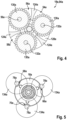
Fig. 5 eine schematische Darstellung eines Einbringens von Planetenradaufnahmen in die Zwischenwelle, -
Fig. 6 die Handwerkzeugmaschine in einer Frontalansicht, -
Fig. 7 eine Schnittdarstellung der nicht erfindungsgemäßen Handwerkzeugmaschine -
Fig. 8 eine Schnittdarstellung einer erfindungsgemäßen Handwerkzeugmaschinenvorrichtung und -
Fig. 9 eine Schnittdarstellung einer weiteren erfindungsgemäßen Handwerkzeugmaschinenvorrichtung. -
Figur 1 zeigt eine Handwerkzeugmaschine 34a, welche als ein Drehschlagschrauber ausgebildet ist, in einer schematischen Teilschnittdarstellung. Die Handwerkzeugmaschine 34a ist als ein Akku-Drehschlagschrauber ausgebildet. Die Handwerkzeugmaschine 34a umfasst einen Handgriff 80, der sich senkrecht zu einer Rotationsachse 84a einer zur Aufnahme eines Einsatzwerkzeugs (hier nicht dargestellt) vorgesehenen Werkzeugaufnahme 86a der Handwerkzeugmaschine 34a erstreckt. Der Handgriff 80a umfasst an einer der Handwerkzeugmaschine 34a abgewandten Seite 88a eine Akkuaufnahme 90a. Die Akkuaufnahme 90a ist dazu vorgesehen, eine Akkueinheit 92a zur Energieversorgung der Handwerkzeugmaschine 34a aufzunehmen. - Ferner weist die Handwerkzeugmaschine 34a eine Handwerkzeugmaschinenvorrichtung 10a mit einer Antriebseinheit 12a und einem Drehschlagwerk 16a auf.
Figur 2 zeigt die Handwerkzeugmaschinenvorrichtung 10 in einer Schnittdarstellung. Die Handwerkzeugmaschinenvorrichtung 10a weist ein Antriebsgehäuse 72a und ein Schlagwerksgehäuse 74a auf (vgl.Figur 1 ). Das Antriebsgehäuse 72a umschließt die Antriebseinheit 12a zumindest im Wesentlichen vollständig. Das Schlagwerksgehäuse 74a umschließt das Drehschlagwerk 16a zumindest im Wesentlichen vollständig (vgl.Figur 1 ). Die Antriebseinheit 12a ist als eine elektrische Antriebseinheit ausgebildet, welche mittels der Akkueinheit 92a mit elektrischer Energie versorgt wird. Die Antriebseinheit 12a weist einen gehäuselosen Elektromotor 26a auf, welcher dazu vorgesehen ist, die von der Akkueinheit 92a bereitgestellte elektrische Energie in Rotationsenergie umzuwandeln. Der Elektromotor 26a ist als Open-Frame Motor ausgebildet, bei dem Bauteile des Elektromotors 26a einzeln im Antriebsgehäuse 72a gelagert sind. Ferner weist die Antriebseinheit 12a eine Antriebswelle 14a auf, welche dazu vorgesehen ist, die Rotationsenergie an das Drehschlagwerk 16a zu übertragen. Die Antriebswelle 14a ist vollständig von einer Ankerwelle 28a des gehäuselosen Elektromotors 26a gebildet. Die Ankerwelle 28a ist einteilig ausgeführt. Das Drehschlagwerk 16a ist als ein V-Nutendrehschlagwerk ausgebildet. Das Drehschlagwerk 16a ist dazu vorgesehen, eine kontinuierliche Leistungsabgabe der Antriebseinheit 12a in einen schlagförmigen Drehimpuls umzusetzen. Die Leistung der Antriebseinheit 12a wird durch einen Schlag eines Schlägers 96a des Drehschlagwerks 16a auf einen korrespondierenden Amboss 100a einer Abtriebsspindel 15a mittels eines Impulses hoher Leistungsintensität an das Einsatzwerkzeug weitergegeben. Der Amboss 100a ist in der dargestellten Ausführungsform einstückig mit der Abtriebsspindel 15a und der Werkzeugaufnahme 86a ausgebildet. Der Schläger 96a ist derart gelagert, dass eine Axialbewegung und Radialbewegung möglich ist. Die Steuerung der Axialbewegung erfolgt durch V-förmige Nuten 98a (vgl.Figur 3 ) und Mitnehmerkugeln 97a (vgl.Figur 1 ). Eine Feder 138a sorgt für die Rückstellbewegung des Schlägers 96a. - Das Drehschlagwerk 16a weist eine Zwischenwelle 18a auf, welche zumindest im Wesentlichen fluchtend zu der Antriebswelle 14a ausgerichtet ist. Des Weiteren weist die Handwerkzeugmaschinenvorrichtung 10a zumindest ein Lager 20a zur Lagerung der Antriebswelle 14a auf. Das Lager 20a ist zumindest teilweise in einer die Zwischenwelle 18a schneidenden Ebene 22a angeordnet, welche zumindest im Wesentlichen senkrecht zur Zwischenwelle 18a verläuft. Die Antriebswelle 14a ist zumindest teilweise innerhalb der Zwischenwelle 18a gelagert. Die Zwischenwelle 18a weist eine Aufnahmeausnehmung 24a auf, welche zu einer zumindest teilweisen Aufnahme der Antriebswelle 14a vorgesehen ist. Die Aufnahmeausnehmung 24a erstreckt sich zumindest im Wesentlichen entlang einer Rotationsachse 108a der Zwischenwelle 18a. Die Antriebswelle 14a ragt in einem montierten Zustand zumindest teilweise in die Zwischenwelle 18a, insbesondere in die Aufnahmeausnehmung 24a der Zwischenwelle 18a, hinein. Das Lager 20a zur Lagerung der Antriebswelle 14a ist innerhalb der Aufnahmeausnehmung 24a angeordnet. Das Lager 20a zur Lagerung der Antriebswelle 14a ist als ein Wälzlager ausgebildet. Die Zwischenwelle 18a weist ferner eine Dichtelementaufnahme 30a auf. Die Dichtelementaufnahme 30a ist unmittelbar an einer Einführöffnung 136a der Aufnahmeausnehmung 24a der Zwischenwelle 18a angeordnet, welche dazu vorgesehen ist, die Antriebswelle 14a in die Zwischenwelle 18a einzuführen. Zudem weist die Zwischenwelle 18a zumindest ein in der Dichtelementaufnahme 30a angeordnetes Dichtelement 32a auf. Das Dichtelement 32a ist als ein Wellendichtring, insbesondere als ein Radial-Wellendichtring ausgebildet, welcher in einem montierten Zustand zwischen der Antriebswelle 14a und der Zwischenwelle 18a angeordnet ist. Die Dichtelementaufnahme 30a ist als eine Wellendichtringaufnahme ausgebildet. Ein weiteres Lager 102a zur Lagerung der Antriebswelle 14a ist an einer der Werkzeugaufnahme 86a abgewandten Seite 104a des Elektromotors 26a im Antriebsgehäuse 72a angeordnet.
- Zudem weist die Handwerkzeugmaschinenvorrichtung 10a eine Kühllufteinheit 36a auf, welche zumindest ein zwischen der Antriebseinheit 12a und dem Drehschlagwerk 16a angeordnetes Lüfterrad 38a umfasst. Das Lüfterrad 38a ist insbesondere zur Erzeugung eines Kühlluftstroms zu einer Kühlung des Drehschlagwerks 16a und/oder der Antriebseinheit 12a vorgesehen. Das Lüfterrad 38a ist drehfest auf der Antriebswelle 14a der Antriebseinheit 12a angeordnet. Die Antriebseinheit 12a ist dazu vorgesehen, das Lüfterrad 38a während eines Betriebs der Handwerkzeugmaschine 34a in eine Rotationsbewegung zu versetzen. Das Lüfterrad 38a und das Drehschlagwerk 16a überlappen sich zumindest teilweise in axialer Richtung 40a. Vorzugsweise überragt das Lüfterrad 38a das Drehschlagwerk 16a in axialer Richtung 40a zumindest teilweise. Das Lüfterrad 38a weist eine Mehrzahl von in Umfangsrichtung angeordneter Lüfterradflügel 110a auf, welche zumindest einen Teil des Drehschlagwerks 16a in Umfangsrichtung übergreifen. Die Lüfterradflügel 110a erstecken sich zumindest im Wesentlichen in axialer Richtung 40a. Das Drehschlagwerk 16a weist zumindest eine als ein einstufiges Planetengetriebe 50a ausgebildete Getriebeeinheit 42a auf. Das Lager 20a zur Lagerung der Antriebswelle 14a ist auf einer der Antriebseinheit 12a abgewandten Seite des Planetengetriebes 50a angeordnet. Eine Verzahnung 144a zwischen der Antriebswelle 14a und dem Planetengetriebe 50a ist zwischen dem Lager 20a und dem Lager 102a angeordnet. Alternativ kann die Getriebeeinheit 42a als ein mehrstufiges Planetengetriebe ausgebildet sein. Vorzugsweise überlappen sich das Lüfterrad 38a und zumindest die Getriebeeinheit 42a zumindest teilweise in axialer Richtung 40a. Das Planetengetriebe 50a umfasst zumindest ein Hohlrad 46a. Ferner umfasst das Drehschlagwerk 16a einen Schlagwerkdeckel 44a. Der Schlagwerkdeckel 44a ist zwischen der Antriebseinheit 12a und dem Planetengetriebe 50a angeordnet. Insbesondere ist der Schlagwerkdeckel 44a dazu vorgesehen, das Drehschlagwerk 16a in Richtung der Antriebseinheit 12a, zumindest zu einem Großteil zu verschließen. Der Schlagwerkdeckel 44a weist eine Durchführungsausnehmung 106a auf, welche zu einer zumindest teilweisen Durchführung zumindest der Antriebswelle 14a vorgesehen ist. Der Schlagwerkdeckel 44a ist einstückig mit dem Hohlrad 46a ausgebildet. Der Schlagwerkdeckel 44a und das Hohlrad 46a bestehen zumindest im Wesentlichen aus einem metallischen Material, insbesondere aus einem metallischen Sintermaterial. Vorzugsweise überlappen sich das Lüfterrad 38a und zumindest der Schlagwerkdeckel 44a zumindest teilweise in axialer Richtung 40a.
- Die Handwerkzeugmaschinenvorrichtung 10 weist ferner ein Zwischenwellenlager 48a zur Lagerung der Zwischenwelle 18a auf. Das Zwischenwellenlager 48a ist als ein Wälzlager ausgebildet. Alternativ kann das Zwischenwellenlager 48a als ein Gleitlager ausgebildet sein. Das Zwischenwellenlager 48a ist als ein Radiallager ausgebildet, welches dazu vorgesehen die Zwischenwelle 18a drehbar in dem Schlagwerkdeckel 44a zu lagern. Das Zwischenwellenlager 48a ist zumindest teilweise innerhalb eines Schlagwerkdeckels 44a des Drehschlagwerks 16a angeordnet. Das Zwischenwellenlager 48a ist unmittelbar an der Durchführungsausnehmung 106a des Schlagwerkdeckels 44a angeordnet. Das Zwischenwellenlager 48a ist auf der Werkzeugaufnahme 86a zugewandten Seite des Schlagwerkdeckels 44a angeordnet. Der Schlagwerkdeckel 44a weist zumindest eine Lageraufnahme 52a auf, welche zu einer Aufnahme des Zwischenwellenlagers 48a vorgesehen ist. Die Lageraufnahme 52a ist einstückig mit dem Schlagwerkdeckel 44a ausgebildet. Die Lageraufnahme 52a ist im Bereich der Durchführungsausnehmung 106a des Schlagwerkdeckels 44a angeordnet. Die Lageraufnahme 52a ist zumindest im Wesentlichen hohlzylindrisch ausgebildet. Die Lageraufnahme 52a weist an einem dem Schlagwerkdeckel 44a abgewandten Ende ein zumindest im Wesentlichen ringförmiges Anschlagelement 112a für das Zwischenwellenlager 48a auf. Das Anschlagelement 112a ist einstückig mit der Lageraufnahme 52a ausgebildet. Ein Innendurchmesser der Lageraufnahme 52a entspricht zumindest im Wesentlichen einem Außendurchmesser des Zwischenwellenlagers 48a. Vorzugsweise ist das Zwischenwellenlager 48a durch einen Presssitz in der Lageraufnahme 52a fixiert. Vorzugsweise überlappen sich das Lüfterrad 38a und zumindest das Zwischenwellenlager 48a und/oder die Zwischenwelle 18a zumindest teilweise in axialer Richtung 40a.
-
Figur 3 zeigt die Zwischenwelle 18a in einer perspektivischen Darstellung.Figur 4 zeigt die Zwischenwelle 18a in einer Schnittdarstellung entlang der Schnittebene III - III. Die Zwischenwelle 18a ist als Planetenradträger 94a des Planetengetriebes 50a ausgebildet. Die Zwischenwelle 18a weist eine in Umfangsrichtung angeordnete Mehrzahl von Planetenradaufnahmen 54a, 56a, 58a und Planetenradlagerstellen 60a, 62a, 64a auf. In jeder Planetenradaufnahme 54a, 56a, 58a ist jeweils ein Planetenrad 130a angeordnet, welches mittels eines Stifts 132a drehbar gelagert ist. Die Zwischenwelle 18a weist zumindest im Bereich zumindest einer Planetenradlagerstelle 60a, 62a, 64a an seinem Außenumfang zumindest eine Materialaussparung 66a, 68a, 70a auf. Eine Anzahl von Materialaussparungen 66a, 68a, 70a entspricht einer Anzahl von Planetenradaufnahmen 54a, 56a, 58a. Jeder Planetenradaufnahme 54a, 56a, 58a ist genau eine Materialaussparung 66a, 68a, 70a zugeordnet. Die Zwischenwelle 18a weist drei Planetenradaufnahmen 54a, 56a, 58a mit jeweils einer Planetenradlagerstelle 60a, 62a, 64a auf. Die Planetenradlagerstellen 60a, 62a, 64a sind zumindest im Wesentlichen um jeweils 120° versetzt zueinander in Umfangsrichtung an der Zwischenwelle 18a angeordnet. Die Planetenradaufnahmen 54a, 56a, 58a sind durch sich radial zu einer Längserstreckungsrichtung 122a der Zwischenwelle 18a erstreckende Stege 124a voneinander getrennt. Entlang der Längserstreckungsrichtung 122a der Zwischenwelle 18a betrachtet, sind die Planetenradaufnahmen 54a, 56a, 58a durch zwei scheibenförmige Wandungselemente 126a, 128a begrenzt, welche zumindest im Wesentlichen senkrecht zur Längserstreckungsrichtung 122a angeordnet sind. Die Wandungselemente 126a, 128a sind zumindest im Wesentlichen kreisförmig ausgebildet. Die Wandungselemente 126a, 128a sind einstückig mit der Zwischenwelle 18a ausgebildet. Die Materialaussparungen 66a, 68a, 70a sind zumindest im Wesentlichen kreissegmentförmig ausgebildet. Die Planetenradaufnahmen 54a, 56a, 58a sind zumindest im Wesentlichen zylindersegmentförmig ausgebildet. Die Materialaussparungen 66a, 68a, 70a sind in eines der Wandungselemente 126a, 128a eingebracht. Die Materialaussparung 66a, 68a, 70a sind in das Wandungselement 126a eingebracht, welches in einem montierten Zustand der Zwischenwelle 18a in Richtung einer Antriebseinheit 12a angeordnet ist. Die Wandungselemente 126a, 128a weisen einen zumindest im Wesentlichen identischen Radius auf. Alternativ kann eines der Wandungselemente 126a, 128a einen geringeren Radius aufweisen. - Die Materialaussparungen 66a, 68a, 70a sind bei einer Herstellung der Zwischenwelle 18a zu einer zeitweisen zumindest teilweisen Aufnahme einer Fräskopfspindel 78a vorgesehen (vgl.
Figur 5 ). Die Planetenradaufnahmen 54a, 56a, 58a werden mittels eines Scheibenfräsers 134a in einen Rohling der Zwischenwelle 18a eingebracht. Während des Einbringens der Planetenradaufnahmen 54a, 56a, 58a wird eine Fräskopfspindel 78a des Scheibenfräsers 134a zumindest teilweise in eine Materialaussparung 66a, 68a, 70a eingeführt. Vorzugsweise werden die Planetenradaufnahmen 54a, 56a, 58a in einem gemeinsamen Verfahrensschritt zumindest im Wesentlichen zeitgleich in die Zwischenwelle 18a, insbesondere mittels einer Mehrzahl identischer Scheibenfräser 134a, eingebracht. Die Scheibenfräser 134a werden derart an die Zwischenwelle 18a herangeführt, dass die Fräskopfspindeln 78a zu jedem Zeitpunkt zumindest im Wesentlichen parallel zu einer Längserstreckungsrichtung 122a der Zwischenwelle 18a verlaufen. -
Figur 6 zeigt die Handwerkzeugmaschine 34a in einer Frontalansicht.Figur 7 zeigt eine Schnittdarstellung der Handwerkzeugmaschine 34a entlang der Schnittlinie VI - VI. Das Hohlrad 46a des Planetengetriebes 50a ist zwischen das Antriebsgehäuse 72a und das Schlagwerksgehäuse 74a geklemmt. Das Antriebsgehäuse 72a und das Schlagwerksgehäuse 74a weisen eine Klemmfläche 114a auf, welche in einem montierten Zustand jeweils von gegenüberliegenden Seiten an zumindest einer Fläche 116a des Hohlrads 46a anliegen und welche jeweils eine Klemmkraft auf das Hohlrad 46a ausüben. Das Hohlrad 46a ist mittels zumindest eines Schraubelements 76a, vorzugsweise mittels zumindest einer Schraube, an dem Antriebsgehäuse 72a fixiert. Das Hohlrad 46a ist beispielhaft mit vier Schraubelementen 76a fixiert. Das Hohlrad 46a weist an einem Außenumfang Ausnehmungen 118a auf, welche zu einem Hindurchführen der Schraubelemente 76a vorgesehen sind. Das Antriebsgehäuse 72a weist eine zur Anzahl der Schraubelemente 76a korrespondierende Anzahl von Gewindeausnehmung 120a auf, welche ein zu einem Gewinde der Schraubelemente 76a korrespondierendes Gewinde aufweisen. Das Antriebsgehäuse 72a, das Schlagwerksgehäuse 74a und das Hohlrad 46a sind in einem montierten Zustand mittels der Schraubelemente 76a miteinander verbunden, wobei das Hohlrad 46a zwischen dem Antriebsgehäuse 72a und dem Schlagwerksgehäuse 74a angeordnet ist. Alternativ oder zusätzlich kann das Hohlrad 46a mittels zumindest eines Schraubelements 76a an dem Schlagwerksgehäuse 74a fixiert sein. - In den
Figuren 8 und 9 ist ein Ausführungsbeispiel der Erfindung gezeigt. Die nachfolgenden Beschreibungen und die Zeichnungen beschränken sich im Wesentlichen auf die Unterschiede zwischen den Ausführungsbeispielen, wobei bezüglich gleich bezeichneter Bauteile, insbesondere in Bezug auf Bauteile mit gleichen Bezugszeichen, grundsätzlich auch auf die Zeichnungen und/oder die Beschreibung der anderen Ausführungsbeispiele, insbesondere derFiguren 1 bis 7 , verwiesen werden kann. Zur Unterscheidung der Ausführungsbeispiele ist der Buchstabe a den Bezugszeichen des Ausführungsbeispiels in denFiguren 1 bis 7 nachgestellt. In den Ausführungsbeispielen derFiguren 1 bis 7 ist der Buchstabe a durch die Buchstaben b bis c ersetzt. -
Figur 8 zeigt eine erfindungsgemäße Ausgestaltung der Handwerkzeugmaschinenvorrichtung 10b in einer Schnittdarstellung. Die Handwerkzeugmaschinenvorrichtung 10b weist eine Antriebseinheit 12b und einem Drehschlagwerk 16b mit einem Planetengetriebe 50b auf. Die Antriebseinheit 12b weist einen gehäuselosen Elektromotor 26b auf, welcher dazu vorgesehen ist, elektrische Energie in Rotationsenergie umzuwandeln. Der Elektromotor 26b ist als Open-Frame Motor ausgebildet. Ferner weist die Antriebseinheit 12b eine Antriebswelle 14b auf, welche dazu vorgesehen ist, die Rotationsenergie an das Drehschlagwerk 16b zu übertragen. Die Antriebswelle 14b ist teilweise von einer Ankerwelle 28b des gehäuselosen Elektromotors 26b gebildet. - Das Drehschlagwerk 16b weist eine Zwischenwelle 18b auf, welche zumindest im Wesentlichen fluchtend zu der Antriebswelle 14b ausgerichtet ist. Des Weiteren weist die Handwerkzeugmaschinenvorrichtung 10b zumindest ein Lager 20b zur Lagerung der Antriebswelle 14b auf. Die Antriebswelle 14b ist zumindest teilweise innerhalb der Zwischenwelle 18b gelagert. Die Zwischenwelle 18b weist eine Aufnahmeausnehmung 24b auf, welche zu einer zumindest teilweisen Aufnahme der Antriebswelle 14b vorgesehen ist. Das Lager 20b ist unmittelbar an einer Einführöffnung 136b der Aufnahmeausnehmung 24b der Zwischenwelle 18b angeordnet, welche dazu vorgesehen ist, die Antriebswelle 14b in die Zwischenwelle 18b einzuführen. Das Lager 20b zur Lagerung der Antriebswelle 14b ist auf einer der Antriebseinheit 12b zugewandten Seite des Planetengetriebes 50b angeordnet. Das Lager 20b ist als ein Rollenlager ausgebildet.
-
Figur 9 zeigt eine weitere erfindungsgemäße Ausgestaltung der Handwerkzeugmaschinenvorrichtung 10c in einer Schnittdarstellung. Die Handwerkzeugmaschinenvorrichtung 10c weist eine Antriebseinheit 12c und einem Drehschlagwerk 16c mit einem Planetengetriebe 50c auf. Die Antriebseinheit 12c weist einen gehäuselosen Elektromotor 26c auf, welcher dazu vorgesehen ist, elektrische Energie in Rotationsenergie umzuwandeln. Der Elektromotor 26c ist als Open-Frame Motor ausgebildet. Ferner weist die Antriebseinheit 12c eine Antriebswelle 14b auf, welche dazu vorgesehen ist, die Rotationsenergie an das Drehschlagwerk 16c zu übertragen. Die Antriebswelle 14c ist teilweise von einer Ankerwelle 28c des gehäuselosen Elektromotors 26c gebildet. - Das Drehschlagwerk 16c weist eine Zwischenwelle 18c auf, welche zumindest im Wesentlichen fluchtend zu der Antriebswelle 14c ausgerichtet ist. Des Weiteren weist die Handwerkzeugmaschinenvorrichtung 10c zumindest ein Lager 20c zur Lagerung der Antriebswelle 14c auf. Die Antriebswelle 14c ist zumindest teilweise innerhalb der Zwischenwelle 18c gelagert. Die Zwischenwelle 18c weist eine Aufnahmeausnehmung 24c auf, welche zu einer zumindest teilweisen Aufnahme der Antriebswelle 14c vorgesehen ist. Das Lager 20c ist unmittelbar an einer Einführöffnung 136c der Aufnahmeausnehmung 24c der Zwischenwelle 18c angeordnet, welche dazu vorgesehen ist, die Antriebswelle 14c in die Zwischenwelle 18c einzuführen. Das Lager 20c zur Lagerung der Antriebswelle 14c ist auf einer der Antriebseinheit 12c zugewandten Seite des Planetengetriebes 50c angeordnet. Das Lager 20c ist als ein Kugellagerlager ausgebildet. Ferner weist die Handwerkzeugmaschinenvorrichtung 10c einen Dichtring 140c auf, welcher das Lager 20c in Umfangsrichtung umschließt und welcher zwischen dem Lager 20c und einem Innendurchmesser Aufnahmeausnehmung 24c der Zwischenwelle 18c angeordnet ist. Die Zwischenwelle 18c weist eine Nut 142c auf, welche zu einer Aufnahme des Dichtrings 140c vorgesehen ist.
Claims (15)
- Handwerkzeugmaschinenvorrichtung mit einer Antriebseinheit (12a; 12b; 12c), welche zumindest eine Antriebswelle (14a; 14b; 14c) aufweist, und mit zumindest einem Drehschlagwerk (16a; 16b; 16c), welches zumindest eine zumindest im Wesentlichen fluchtend zu der Antriebswelle (14a; 14b; 14c) ausgerichtete Zwischenwelle (18a; 18b; 18c) aufweist, und mit zumindest einem Lager (20a; 20b; 20c) zur Lagerung der Antriebswelle (14a; 14b; 14c), wobei das Lager (20) zumindest teilweise in einer die Zwischenwelle (18a; 18b; 18c) schneidenden Ebene (22a; 22b; 22c) angeordnet ist, welche zumindest im Wesentlichen senkrecht zur Zwischenwelle (18a; 18b; 18c) verläuft, und mit einem Zwischenwellenlager (48a; 48b; 48c) zur Lagerung der Zwischenwelle (18a; 18b; 18c), wobei das Lager (20) radial zwischen der Antriebswelle (14a; 14b; 14c) und der Zwischenwelle (18a; 18b; 18c) angeordnet ist dadurch gekennzeichnet, dass die Zwischenwelle (18a; 18b; 18c) zumindest abschnittsweise radial zwischen dem Lager (20) und dem Zwischenwellenlager (48a; 48b; 48c) angeordnet ist.
- Handwerkzeugmaschinenvorrichtung nach Anspruch 1, dadurch gekennzeichnet, dass die Antriebswelle (14a; 14b; 14c) zumindest teilweise innerhalb der Zwischenwelle (18a; 18b; 18c) gelagert ist.
- Handwerkzeugmaschinenvorrichtung nach Anspruch 1 oder 2, dadurch gekennzeichnet, dass die Zwischenwelle (18a; 18b; 18c) zumindest eine Aufnahmeausnehmung (24a; 24b; 24c) aufweist, welche zu einer zumindest teilweisen Aufnahme der Antriebswelle (14a; 14b; 14c) vorgesehen ist.
- Handwerkzeugmaschinenvorrichtung nach Anspruch 3, dadurch gekennzeichnet, dass das Lager (20a; 20b; 20c) zumindest teilweise innerhalb der Aufnahmeausnehmung (24a; 24b; 24c) angeordnet ist.
- Handwerkzeugmaschinenvorrichtung nach einem der vorhergehenden Ansprüche, dadurch gekennzeichnet, dass das Lager (20a; 20b; 20c) zumindest teilweise als ein Wälzlager ausgebildet ist.
- Handwerkzeugmaschinenvorrichtung nach einem der vorhergehenden Ansprüche,
dadurch gekennzeichnet, dass die Antriebseinheit (12a; 12b; 12c) zumindest einen gehäuselosen Elektromotor (26a; 26b; 26c) aufweist. - Handwerkzeugmaschinenvorrichtung nach Anspruch 6, dadurch gekennzeichnet, dass die Antriebswelle (14a; 14b; 14c) zumindest teilweise von einer Ankerwelle (28a; 28b; 28c) des gehäuselosen Elektromotors (26a; 26b; 26c) gebildet ist.
- Handwerkzeugmaschinenvorrichtung nach einem der vorhergehenden Ansprüche,
dadurch gekennzeichnet, dass die Zwischenwelle (18a; 18b; 18c) zumindest eine Dichtelementaufnahme (30a; 30b; 30c) aufweist. - Handwerkzeugmaschinenvorrichtung nach Anspruch 8, dadurch gekennzeichnet, dass die Zwischenwelle (18a; 18b; 18c) zumindest ein in der Dichtelementaufnahme (30a; 30b; 30c) angeordnetes Dichtelement (32a; 32b; 32c) aufweist.
- Handwerkzeugmaschinenvorrichtung nach einem der vorhergehenden Ansprüche,
dadurch gekennzeichnet, dass eine Länge der Handwerkzeugmaschinenvorrichtung maximal 200 mm, insbesondere maximal 160 mm, ganz insbesondere maximal 140 mm, besonders bevorzugt maximal 130 mm beträgt. - Handwerkzeugmaschinenvorrichtung nach einem der vorhergehenden Ansprüche,
dadurch gekennzeichnet, dass das Lager (20) und das Zwischenwellenlager (48a; 48b; 48c) zumindest abschnittsweise überlappend zueinander angeordnet sind. - Handwerkzeugmaschinenvorrichtung nach Anspruch 11, dadurch gekennzeichnet, dass das Zwischenwellenlager (48a; 48b, 48c) zumindest teilweise innerhalb eines Schlagwerkdeckels (44a; 44b; 44c) des Drehschlagwerks (16a; 16b; 16c) angeordnet ist.
- Handwerkzeugmaschinenvorrichtung nach Anspruch 11 oder 12, dadurch gekennzeichnet, dass das Zwischenwellenlager (48a; 48b; 48c) unmittelbar an einer Durchführungsausnehmung (106a; 106b; 106c) des Schlagwerkdeckels (44a; 44b; 44c) angeordnet ist.
- Handwerkzeugmaschinenvorrichtung nach Anspruch 12 oder 13, dadurch gekennzeichnet, dass der Schlagwerkdeckel (44a; 44b; 44c) zumindest eine Lageraufnahme (52a; 52b; 52c) aufweist, welche zu einer Aufnahme des Zwischenwellenlagers (48a; 48b; 48c) vorgesehen ist.
- Handwerkzeugmaschine mit zumindest einer Handwerkzeugmaschinenvorrichtung (10a; 10b; 10c) nach einem der vorhergehenden Ansprüche.
Applications Claiming Priority (4)
| Application Number | Priority Date | Filing Date | Title |
|---|---|---|---|
| DE102016212607 | 2016-07-11 | ||
| DE102017211772.9A DE102017211772A1 (de) | 2016-07-11 | 2017-07-10 | Handwerkzeugmaschinenvorrichtung |
| PCT/EP2017/067398 WO2018011203A1 (de) | 2016-07-11 | 2017-07-11 | Handwerkzeugmaschinenvorrichtung |
| EP17739956.5A EP3481593B1 (de) | 2016-07-11 | 2017-07-11 | Handwerkzeugmaschinenvorrichtung |
Related Parent Applications (2)
| Application Number | Title | Priority Date | Filing Date |
|---|---|---|---|
| EP17739956.5A Division-Into EP3481593B1 (de) | 2016-07-11 | 2017-07-11 | Handwerkzeugmaschinenvorrichtung |
| EP17739956.5A Division EP3481593B1 (de) | 2016-07-11 | 2017-07-11 | Handwerkzeugmaschinenvorrichtung |
Publications (2)
| Publication Number | Publication Date |
|---|---|
| EP4008488A1 EP4008488A1 (de) | 2022-06-08 |
| EP4008488B1 true EP4008488B1 (de) | 2025-05-14 |
Family
ID=60676436
Family Applications (2)
| Application Number | Title | Priority Date | Filing Date |
|---|---|---|---|
| EP21216030.3A Active EP4008488B1 (de) | 2016-07-11 | 2017-07-11 | Handwerkzeugmaschinenvorrichtung |
| EP17739956.5A Active EP3481593B1 (de) | 2016-07-11 | 2017-07-11 | Handwerkzeugmaschinenvorrichtung |
Family Applications After (1)
| Application Number | Title | Priority Date | Filing Date |
|---|---|---|---|
| EP17739956.5A Active EP3481593B1 (de) | 2016-07-11 | 2017-07-11 | Handwerkzeugmaschinenvorrichtung |
Country Status (6)
| Country | Link |
|---|---|
| US (1) | US11148275B2 (de) |
| EP (2) | EP4008488B1 (de) |
| JP (1) | JP6916819B2 (de) |
| CN (1) | CN109476006B (de) |
| DE (1) | DE102017211772A1 (de) |
| WO (1) | WO2018011203A1 (de) |
Families Citing this family (5)
| Publication number | Priority date | Publication date | Assignee | Title |
|---|---|---|---|---|
| US20250042004A1 (en) * | 2021-12-01 | 2025-02-06 | Milwaukee Electric Tool Corporation | Rotary impact tool |
| JP7820242B2 (ja) * | 2022-06-07 | 2026-02-25 | 株式会社マキタ | インパクト工具 |
| EP4302926B1 (de) | 2022-06-16 | 2025-08-06 | Milwaukee Electric Tool Corporation | Kompaktes schlagwerkzeug |
| EP4410489A1 (de) | 2022-11-21 | 2024-08-07 | Milwaukee Electric Tool Corporation | Elektrowerkzeug mit integriertem getriebegehäuse |
| USD1090213S1 (en) | 2023-10-26 | 2025-08-26 | Snap-On Incorporated | Tool housing |
Family Cites Families (27)
| Publication number | Priority date | Publication date | Assignee | Title |
|---|---|---|---|---|
| US2662434A (en) * | 1952-02-28 | 1953-12-15 | Millers Falis Company | Power-operated rotary impact wrench |
| DE3801972A1 (de) * | 1988-01-23 | 1989-08-03 | Wagner Paul Heinz | Kraftschrauber |
| US5136197A (en) | 1991-06-25 | 1992-08-04 | Clarence Hallett | Reaction containment drive for power tool |
| US5361853A (en) * | 1991-11-29 | 1994-11-08 | Ryobi Limited | Power tool |
| US5897454A (en) * | 1996-01-31 | 1999-04-27 | Black & Decker Inc. | Automatic variable transmission for power tool |
| GB0111535D0 (en) * | 2001-05-11 | 2001-07-04 | Johnson Electric Sa | Gear motor for power tool |
| JP2005066790A (ja) * | 2003-08-26 | 2005-03-17 | Ryobi Ltd | 電動工具 |
| JP2005066804A (ja) * | 2003-08-27 | 2005-03-17 | Ryobi Ltd | 電動工具 |
| JP4291173B2 (ja) * | 2004-02-10 | 2009-07-08 | 株式会社マキタ | インパクトドライバ |
| JP4405900B2 (ja) * | 2004-03-10 | 2010-01-27 | 株式会社マキタ | インパクトドライバ |
| US7308948B2 (en) * | 2004-10-28 | 2007-12-18 | Makita Corporation | Electric power tool |
| US20060237205A1 (en) * | 2005-04-21 | 2006-10-26 | Eastway Fair Company Limited | Mode selector mechanism for an impact driver |
| US8627900B2 (en) * | 2008-05-29 | 2014-01-14 | Hitachi Koki Co., Ltd. | Electric power tool |
| EP2674259B1 (de) * | 2009-12-18 | 2017-11-01 | Techtronic Power Tools Technology Limited | Multifunktionswerkzeugsystem |
| US8584770B2 (en) * | 2010-03-23 | 2013-11-19 | Black & Decker Inc. | Spindle bearing arrangement for a power tool |
| DE102011007691A1 (de) * | 2010-11-29 | 2012-05-31 | Robert Bosch Gmbh | Hammerschlagwerk |
| CN103009349A (zh) * | 2010-11-30 | 2013-04-03 | 日立工机株式会社 | 冲击工具 |
| JP5744639B2 (ja) * | 2011-06-17 | 2015-07-08 | 株式会社マキタ | 電動工具 |
| JP5744669B2 (ja) * | 2011-08-05 | 2015-07-08 | 株式会社マキタ | 電動工具 |
| DE102012208031A1 (de) | 2012-05-14 | 2013-11-14 | Robert Bosch Gmbh | +Hybrid integriertes Bauteil und Verfahren zu dessen Herstellung |
| JP6050110B2 (ja) * | 2012-12-27 | 2016-12-21 | 株式会社マキタ | インパクト工具 |
| CN104936746B (zh) * | 2013-01-24 | 2017-06-09 | 日立工机株式会社 | 电动工具 |
| JP6198515B2 (ja) * | 2013-08-08 | 2017-09-20 | 株式会社マキタ | インパクト工具 |
| DE102014217350B4 (de) * | 2014-08-29 | 2022-03-24 | Seg Automotive Germany Gmbh | Elektrische Maschine mit einem als Antriebslager ausgebildeten Gehäuse und darin gelagertem Hohlrad |
| JP6526533B2 (ja) | 2015-09-24 | 2019-06-05 | 株式会社マキタ | 回転打撃工具 |
| DE202016103701U1 (de) | 2016-07-11 | 2016-07-25 | Robert Bosch Gmbh | Handwerkzeugmaschinenvorrichtung |
| CN206200848U (zh) | 2016-11-04 | 2017-05-31 | 浙江意达电器有限公司 | 一种双重密封冲击扳手 |
-
2017
- 2017-07-10 DE DE102017211772.9A patent/DE102017211772A1/de not_active Withdrawn
- 2017-07-11 EP EP21216030.3A patent/EP4008488B1/de active Active
- 2017-07-11 US US16/316,835 patent/US11148275B2/en active Active
- 2017-07-11 WO PCT/EP2017/067398 patent/WO2018011203A1/de not_active Ceased
- 2017-07-11 CN CN201780043155.5A patent/CN109476006B/zh active Active
- 2017-07-11 EP EP17739956.5A patent/EP3481593B1/de active Active
- 2017-07-11 JP JP2018564952A patent/JP6916819B2/ja active Active
Also Published As
| Publication number | Publication date |
|---|---|
| DE102017211772A1 (de) | 2018-01-11 |
| CN109476006A (zh) | 2019-03-15 |
| EP3481593B1 (de) | 2022-01-26 |
| JP2019524457A (ja) | 2019-09-05 |
| WO2018011203A1 (de) | 2018-01-18 |
| CN109476006B (zh) | 2022-08-30 |
| EP4008488A1 (de) | 2022-06-08 |
| US11148275B2 (en) | 2021-10-19 |
| US20190291259A1 (en) | 2019-09-26 |
| JP6916819B2 (ja) | 2021-08-11 |
| EP3481593A1 (de) | 2019-05-15 |
Similar Documents
| Publication | Publication Date | Title |
|---|---|---|
| EP3481594B1 (de) | Handwerkzeugmaschinenvorrichtung | |
| EP4008488B1 (de) | Handwerkzeugmaschinenvorrichtung | |
| EP3481591B1 (de) | Handwerkzeugmaschinenvorrichtung | |
| EP2636490B1 (de) | Motorisch angetriebene Werkzeugmaschine | |
| EP1924407B1 (de) | Handbohrmaschine mit schaltgetriebe | |
| EP0868264B1 (de) | Elektrohandwerkzeugmaschine | |
| EP2364817A2 (de) | Bohrhammervorrichtung | |
| EP3481590B1 (de) | Handwerkzeugmaschinenvorrichtung | |
| EP3053708B1 (de) | Zubehörvorrichtung | |
| EP2709801A1 (de) | Werkzeugaufnahme | |
| DE102016214616A1 (de) | Vorsatzvorrichtung | |
| DE202016103701U1 (de) | Handwerkzeugmaschinenvorrichtung | |
| EP2655018A1 (de) | Handwerkzeugmaschine | |
| EP3332918B1 (de) | Handwerkzeugmaschinenvorrichtung | |
| EP3481596B1 (de) | Handwerkzeugmaschinenvorrichtung | |
| EP3274132B1 (de) | Handwerkzeugmaschine | |
| DE102012215458A1 (de) | Werkzeugmaschine | |
| WO2012089637A2 (de) | Handwerkzeugmaschinenspannvorrichtung | |
| EP3943226A1 (de) | Bohrmaschine | |
| EP4389356A1 (de) | Handwerkzeugmaschine | |
| DE3300715C2 (de) | Tragbares kraftangetriebenes Drehschlagwerkzeug | |
| EP3639979A1 (de) | Handwerkzeugmaschine | |
| DE102017210288A1 (de) | Bohrwerkzeug | |
| DE202012011947U1 (de) | Handwerkzeugmaschinenschlagwerkvorrichtung | |
| DE102015211555A1 (de) | Werkzeugaufnahme |
Legal Events
| Date | Code | Title | Description |
|---|---|---|---|
| PUAI | Public reference made under article 153(3) epc to a published international application that has entered the european phase |
Free format text: ORIGINAL CODE: 0009012 |
|
| STAA | Information on the status of an ep patent application or granted ep patent |
Free format text: STATUS: THE APPLICATION HAS BEEN PUBLISHED |
|
| AC | Divisional application: reference to earlier application |
Ref document number: 3481593 Country of ref document: EP Kind code of ref document: P |
|
| AK | Designated contracting states |
Kind code of ref document: A1 Designated state(s): AL AT BE BG CH CY CZ DE DK EE ES FI FR GB GR HR HU IE IS IT LI LT LU LV MC MK MT NL NO PL PT RO RS SE SI SK SM TR |
|
| STAA | Information on the status of an ep patent application or granted ep patent |
Free format text: STATUS: REQUEST FOR EXAMINATION WAS MADE |
|
| 17P | Request for examination filed |
Effective date: 20221208 |
|
| RBV | Designated contracting states (corrected) |
Designated state(s): AL AT BE BG CH CY CZ DE DK EE ES FI FR GB GR HR HU IE IS IT LI LT LU LV MC MK MT NL NO PL PT RO RS SE SI SK SM TR |
|
| P01 | Opt-out of the competence of the unified patent court (upc) registered |
Effective date: 20230509 |
|
| GRAP | Despatch of communication of intention to grant a patent |
Free format text: ORIGINAL CODE: EPIDOSNIGR1 |
|
| STAA | Information on the status of an ep patent application or granted ep patent |
Free format text: STATUS: GRANT OF PATENT IS INTENDED |
|
| INTG | Intention to grant announced |
Effective date: 20250123 |
|
| GRAS | Grant fee paid |
Free format text: ORIGINAL CODE: EPIDOSNIGR3 |
|
| GRAA | (expected) grant |
Free format text: ORIGINAL CODE: 0009210 |
|
| STAA | Information on the status of an ep patent application or granted ep patent |
Free format text: STATUS: THE PATENT HAS BEEN GRANTED |
|
| AC | Divisional application: reference to earlier application |
Ref document number: 3481593 Country of ref document: EP Kind code of ref document: P |
|
| AK | Designated contracting states |
Kind code of ref document: B1 Designated state(s): AL AT BE BG CH CY CZ DE DK EE ES FI FR GB GR HR HU IE IS IT LI LT LU LV MC MK MT NL NO PL PT RO RS SE SI SK SM TR |
|
| REG | Reference to a national code |
Ref country code: GB Ref legal event code: FG4D Free format text: NOT ENGLISH |
|
| REG | Reference to a national code |
Ref country code: CH Ref legal event code: EP |
|
| REG | Reference to a national code |
Ref country code: IE Ref legal event code: FG4D Free format text: LANGUAGE OF EP DOCUMENT: GERMAN |
|
| REG | Reference to a national code |
Ref country code: DE Ref legal event code: R096 Ref document number: 502017016857 Country of ref document: DE |
|
| REG | Reference to a national code |
Ref country code: NL Ref legal event code: MP Effective date: 20250514 |
|
| PG25 | Lapsed in a contracting state [announced via postgrant information from national office to epo] |
Ref country code: PT Free format text: LAPSE BECAUSE OF FAILURE TO SUBMIT A TRANSLATION OF THE DESCRIPTION OR TO PAY THE FEE WITHIN THE PRESCRIBED TIME-LIMIT Effective date: 20250915 Ref country code: FI Free format text: LAPSE BECAUSE OF FAILURE TO SUBMIT A TRANSLATION OF THE DESCRIPTION OR TO PAY THE FEE WITHIN THE PRESCRIBED TIME-LIMIT Effective date: 20250514 Ref country code: ES Free format text: LAPSE BECAUSE OF FAILURE TO SUBMIT A TRANSLATION OF THE DESCRIPTION OR TO PAY THE FEE WITHIN THE PRESCRIBED TIME-LIMIT Effective date: 20250514 |
|
| PGFP | Annual fee paid to national office [announced via postgrant information from national office to epo] |
Ref country code: DE Payment date: 20250924 Year of fee payment: 9 |
|
| REG | Reference to a national code |
Ref country code: LT Ref legal event code: MG9D |
|
| PG25 | Lapsed in a contracting state [announced via postgrant information from national office to epo] |
Ref country code: GR Free format text: LAPSE BECAUSE OF FAILURE TO SUBMIT A TRANSLATION OF THE DESCRIPTION OR TO PAY THE FEE WITHIN THE PRESCRIBED TIME-LIMIT Effective date: 20250815 Ref country code: NO Free format text: LAPSE BECAUSE OF FAILURE TO SUBMIT A TRANSLATION OF THE DESCRIPTION OR TO PAY THE FEE WITHIN THE PRESCRIBED TIME-LIMIT Effective date: 20250814 |
|
| PG25 | Lapsed in a contracting state [announced via postgrant information from national office to epo] |
Ref country code: NL Free format text: LAPSE BECAUSE OF FAILURE TO SUBMIT A TRANSLATION OF THE DESCRIPTION OR TO PAY THE FEE WITHIN THE PRESCRIBED TIME-LIMIT Effective date: 20250514 Ref country code: PL Free format text: LAPSE BECAUSE OF FAILURE TO SUBMIT A TRANSLATION OF THE DESCRIPTION OR TO PAY THE FEE WITHIN THE PRESCRIBED TIME-LIMIT Effective date: 20250514 |
|
| PG25 | Lapsed in a contracting state [announced via postgrant information from national office to epo] |
Ref country code: BG Free format text: LAPSE BECAUSE OF FAILURE TO SUBMIT A TRANSLATION OF THE DESCRIPTION OR TO PAY THE FEE WITHIN THE PRESCRIBED TIME-LIMIT Effective date: 20250514 |
|
| PGFP | Annual fee paid to national office [announced via postgrant information from national office to epo] |
Ref country code: GB Payment date: 20250724 Year of fee payment: 9 |
|
| PG25 | Lapsed in a contracting state [announced via postgrant information from national office to epo] |
Ref country code: HR Free format text: LAPSE BECAUSE OF FAILURE TO SUBMIT A TRANSLATION OF THE DESCRIPTION OR TO PAY THE FEE WITHIN THE PRESCRIBED TIME-LIMIT Effective date: 20250514 |
|
| PGFP | Annual fee paid to national office [announced via postgrant information from national office to epo] |
Ref country code: FR Payment date: 20250723 Year of fee payment: 9 |
|
| PG25 | Lapsed in a contracting state [announced via postgrant information from national office to epo] |
Ref country code: RS Free format text: LAPSE BECAUSE OF FAILURE TO SUBMIT A TRANSLATION OF THE DESCRIPTION OR TO PAY THE FEE WITHIN THE PRESCRIBED TIME-LIMIT Effective date: 20250814 |
|
| PG25 | Lapsed in a contracting state [announced via postgrant information from national office to epo] |
Ref country code: IS Free format text: LAPSE BECAUSE OF FAILURE TO SUBMIT A TRANSLATION OF THE DESCRIPTION OR TO PAY THE FEE WITHIN THE PRESCRIBED TIME-LIMIT Effective date: 20250914 |
|
| PG25 | Lapsed in a contracting state [announced via postgrant information from national office to epo] |
Ref country code: LV Free format text: LAPSE BECAUSE OF FAILURE TO SUBMIT A TRANSLATION OF THE DESCRIPTION OR TO PAY THE FEE WITHIN THE PRESCRIBED TIME-LIMIT Effective date: 20250514 |
|
| PG25 | Lapsed in a contracting state [announced via postgrant information from national office to epo] |
Ref country code: DK Free format text: LAPSE BECAUSE OF FAILURE TO SUBMIT A TRANSLATION OF THE DESCRIPTION OR TO PAY THE FEE WITHIN THE PRESCRIBED TIME-LIMIT Effective date: 20250514 Ref country code: SM Free format text: LAPSE BECAUSE OF FAILURE TO SUBMIT A TRANSLATION OF THE DESCRIPTION OR TO PAY THE FEE WITHIN THE PRESCRIBED TIME-LIMIT Effective date: 20250514 |
|
| PG25 | Lapsed in a contracting state [announced via postgrant information from national office to epo] |
Ref country code: CZ Free format text: LAPSE BECAUSE OF FAILURE TO SUBMIT A TRANSLATION OF THE DESCRIPTION OR TO PAY THE FEE WITHIN THE PRESCRIBED TIME-LIMIT Effective date: 20250514 |
|
| PG25 | Lapsed in a contracting state [announced via postgrant information from national office to epo] |
Ref country code: EE Free format text: LAPSE BECAUSE OF FAILURE TO SUBMIT A TRANSLATION OF THE DESCRIPTION OR TO PAY THE FEE WITHIN THE PRESCRIBED TIME-LIMIT Effective date: 20250514 |
|
| PG25 | Lapsed in a contracting state [announced via postgrant information from national office to epo] |
Ref country code: SK Free format text: LAPSE BECAUSE OF FAILURE TO SUBMIT A TRANSLATION OF THE DESCRIPTION OR TO PAY THE FEE WITHIN THE PRESCRIBED TIME-LIMIT Effective date: 20250514 Ref country code: RO Free format text: LAPSE BECAUSE OF FAILURE TO SUBMIT A TRANSLATION OF THE DESCRIPTION OR TO PAY THE FEE WITHIN THE PRESCRIBED TIME-LIMIT Effective date: 20250514 |
|
| PG25 | Lapsed in a contracting state [announced via postgrant information from national office to epo] |
Ref country code: IT Free format text: LAPSE BECAUSE OF FAILURE TO SUBMIT A TRANSLATION OF THE DESCRIPTION OR TO PAY THE FEE WITHIN THE PRESCRIBED TIME-LIMIT Effective date: 20250514 |
|
| REG | Reference to a national code |
Ref country code: DE Ref legal event code: R097 Ref document number: 502017016857 Country of ref document: DE |
|
| REG | Reference to a national code |
Ref country code: CH Ref legal event code: H13 Free format text: ST27 STATUS EVENT CODE: U-0-0-H10-H13 (AS PROVIDED BY THE NATIONAL OFFICE) Effective date: 20260224 |
|
| PG25 | Lapsed in a contracting state [announced via postgrant information from national office to epo] |
Ref country code: LU Free format text: LAPSE BECAUSE OF NON-PAYMENT OF DUE FEES Effective date: 20250711 |
|
| PLBE | No opposition filed within time limit |
Free format text: ORIGINAL CODE: 0009261 |
|
| STAA | Information on the status of an ep patent application or granted ep patent |
Free format text: STATUS: NO OPPOSITION FILED WITHIN TIME LIMIT |
|
| REG | Reference to a national code |
Ref country code: CH Ref legal event code: L10 Free format text: ST27 STATUS EVENT CODE: U-0-0-L10-L00 (AS PROVIDED BY THE NATIONAL OFFICE) Effective date: 20260325 |
|
| REG | Reference to a national code |
Ref country code: BE Ref legal event code: MM Effective date: 20250731 |
|
| PG25 | Lapsed in a contracting state [announced via postgrant information from national office to epo] |
Ref country code: BE Free format text: LAPSE BECAUSE OF NON-PAYMENT OF DUE FEES Effective date: 20250731 |
|
| 26N | No opposition filed |
Effective date: 20260217 |
|
| PG25 | Lapsed in a contracting state [announced via postgrant information from national office to epo] |
Ref country code: CH Free format text: LAPSE BECAUSE OF NON-PAYMENT OF DUE FEES Effective date: 20250731 |