EP4008524A1 - Procédé et système de fabrication, appareil d'impression 3d et procédé de traitement d'image - Google Patents
Procédé et système de fabrication, appareil d'impression 3d et procédé de traitement d'image Download PDFInfo
- Publication number
- EP4008524A1 EP4008524A1 EP20846232.5A EP20846232A EP4008524A1 EP 4008524 A1 EP4008524 A1 EP 4008524A1 EP 20846232 A EP20846232 A EP 20846232A EP 4008524 A1 EP4008524 A1 EP 4008524A1
- Authority
- EP
- European Patent Office
- Prior art keywords
- dental restoration
- area
- layer
- printing apparatus
- coating
- Prior art date
- Legal status (The legal status is an assumption and is not a legal conclusion. Google has not performed a legal analysis and makes no representation as to the accuracy of the status listed.)
- Pending
Links
Images




Classifications
-
- B—PERFORMING OPERATIONS; TRANSPORTING
- B29—WORKING OF PLASTICS; WORKING OF SUBSTANCES IN A PLASTIC STATE IN GENERAL
- B29C—SHAPING OR JOINING OF PLASTICS; SHAPING OF MATERIAL IN A PLASTIC STATE, NOT OTHERWISE PROVIDED FOR; AFTER-TREATMENT OF THE SHAPED PRODUCTS, e.g. REPAIRING
- B29C64/00—Additive manufacturing, i.e. manufacturing of three-dimensional [3D] objects by additive deposition, additive agglomeration or additive layering, e.g. by 3D printing, stereolithography or selective laser sintering
- B29C64/10—Processes of additive manufacturing
- B29C64/106—Processes of additive manufacturing using only liquids or viscous materials, e.g. depositing a continuous bead of viscous material
- B29C64/124—Processes of additive manufacturing using only liquids or viscous materials, e.g. depositing a continuous bead of viscous material using layers of liquid which are selectively solidified
-
- A—HUMAN NECESSITIES
- A61—MEDICAL OR VETERINARY SCIENCE; HYGIENE
- A61C—DENTISTRY; APPARATUS OR METHODS FOR ORAL OR DENTAL HYGIENE
- A61C13/00—Dental prostheses; Making same
- A61C13/0003—Making bridge-work, inlays, implants or the like
- A61C13/0006—Production methods
- A61C13/0013—Production methods using stereolithographic techniques
-
- A—HUMAN NECESSITIES
- A61—MEDICAL OR VETERINARY SCIENCE; HYGIENE
- A61C—DENTISTRY; APPARATUS OR METHODS FOR ORAL OR DENTAL HYGIENE
- A61C13/00—Dental prostheses; Making same
- A61C13/0003—Making bridge-work, inlays, implants or the like
- A61C13/0022—Blanks or green, unfinished dental restoration parts
-
- A—HUMAN NECESSITIES
- A61—MEDICAL OR VETERINARY SCIENCE; HYGIENE
- A61C—DENTISTRY; APPARATUS OR METHODS FOR ORAL OR DENTAL HYGIENE
- A61C13/00—Dental prostheses; Making same
- A61C13/08—Artificial teeth; Making same
- A61C13/082—Cosmetic aspects, e.g. inlays; Determination of the colour
-
- B—PERFORMING OPERATIONS; TRANSPORTING
- B29—WORKING OF PLASTICS; WORKING OF SUBSTANCES IN A PLASTIC STATE IN GENERAL
- B29C—SHAPING OR JOINING OF PLASTICS; SHAPING OF MATERIAL IN A PLASTIC STATE, NOT OTHERWISE PROVIDED FOR; AFTER-TREATMENT OF THE SHAPED PRODUCTS, e.g. REPAIRING
- B29C64/00—Additive manufacturing, i.e. manufacturing of three-dimensional [3D] objects by additive deposition, additive agglomeration or additive layering, e.g. by 3D printing, stereolithography or selective laser sintering
- B29C64/20—Apparatus for additive manufacturing; Details thereof or accessories therefor
- B29C64/205—Means for applying layers
-
- B—PERFORMING OPERATIONS; TRANSPORTING
- B29—WORKING OF PLASTICS; WORKING OF SUBSTANCES IN A PLASTIC STATE IN GENERAL
- B29C—SHAPING OR JOINING OF PLASTICS; SHAPING OF MATERIAL IN A PLASTIC STATE, NOT OTHERWISE PROVIDED FOR; AFTER-TREATMENT OF THE SHAPED PRODUCTS, e.g. REPAIRING
- B29C64/00—Additive manufacturing, i.e. manufacturing of three-dimensional [3D] objects by additive deposition, additive agglomeration or additive layering, e.g. by 3D printing, stereolithography or selective laser sintering
- B29C64/20—Apparatus for additive manufacturing; Details thereof or accessories therefor
- B29C64/227—Driving means
-
- B—PERFORMING OPERATIONS; TRANSPORTING
- B29—WORKING OF PLASTICS; WORKING OF SUBSTANCES IN A PLASTIC STATE IN GENERAL
- B29C—SHAPING OR JOINING OF PLASTICS; SHAPING OF MATERIAL IN A PLASTIC STATE, NOT OTHERWISE PROVIDED FOR; AFTER-TREATMENT OF THE SHAPED PRODUCTS, e.g. REPAIRING
- B29C64/00—Additive manufacturing, i.e. manufacturing of three-dimensional [3D] objects by additive deposition, additive agglomeration or additive layering, e.g. by 3D printing, stereolithography or selective laser sintering
- B29C64/20—Apparatus for additive manufacturing; Details thereof or accessories therefor
- B29C64/227—Driving means
- B29C64/232—Driving means for motion along the axis orthogonal to the plane of a layer
-
- B—PERFORMING OPERATIONS; TRANSPORTING
- B29—WORKING OF PLASTICS; WORKING OF SUBSTANCES IN A PLASTIC STATE IN GENERAL
- B29C—SHAPING OR JOINING OF PLASTICS; SHAPING OF MATERIAL IN A PLASTIC STATE, NOT OTHERWISE PROVIDED FOR; AFTER-TREATMENT OF THE SHAPED PRODUCTS, e.g. REPAIRING
- B29C64/00—Additive manufacturing, i.e. manufacturing of three-dimensional [3D] objects by additive deposition, additive agglomeration or additive layering, e.g. by 3D printing, stereolithography or selective laser sintering
- B29C64/20—Apparatus for additive manufacturing; Details thereof or accessories therefor
- B29C64/245—Platforms or substrates
-
- B—PERFORMING OPERATIONS; TRANSPORTING
- B29—WORKING OF PLASTICS; WORKING OF SUBSTANCES IN A PLASTIC STATE IN GENERAL
- B29C—SHAPING OR JOINING OF PLASTICS; SHAPING OF MATERIAL IN A PLASTIC STATE, NOT OTHERWISE PROVIDED FOR; AFTER-TREATMENT OF THE SHAPED PRODUCTS, e.g. REPAIRING
- B29C64/00—Additive manufacturing, i.e. manufacturing of three-dimensional [3D] objects by additive deposition, additive agglomeration or additive layering, e.g. by 3D printing, stereolithography or selective laser sintering
- B29C64/20—Apparatus for additive manufacturing; Details thereof or accessories therefor
- B29C64/264—Arrangements for irradiation
-
- B—PERFORMING OPERATIONS; TRANSPORTING
- B29—WORKING OF PLASTICS; WORKING OF SUBSTANCES IN A PLASTIC STATE IN GENERAL
- B29C—SHAPING OR JOINING OF PLASTICS; SHAPING OF MATERIAL IN A PLASTIC STATE, NOT OTHERWISE PROVIDED FOR; AFTER-TREATMENT OF THE SHAPED PRODUCTS, e.g. REPAIRING
- B29C64/00—Additive manufacturing, i.e. manufacturing of three-dimensional [3D] objects by additive deposition, additive agglomeration or additive layering, e.g. by 3D printing, stereolithography or selective laser sintering
- B29C64/30—Auxiliary operations or equipment
-
- B—PERFORMING OPERATIONS; TRANSPORTING
- B29—WORKING OF PLASTICS; WORKING OF SUBSTANCES IN A PLASTIC STATE IN GENERAL
- B29C—SHAPING OR JOINING OF PLASTICS; SHAPING OF MATERIAL IN A PLASTIC STATE, NOT OTHERWISE PROVIDED FOR; AFTER-TREATMENT OF THE SHAPED PRODUCTS, e.g. REPAIRING
- B29C64/00—Additive manufacturing, i.e. manufacturing of three-dimensional [3D] objects by additive deposition, additive agglomeration or additive layering, e.g. by 3D printing, stereolithography or selective laser sintering
- B29C64/30—Auxiliary operations or equipment
- B29C64/307—Handling of material to be used in additive manufacturing
- B29C64/321—Feeding
-
- B—PERFORMING OPERATIONS; TRANSPORTING
- B29—WORKING OF PLASTICS; WORKING OF SUBSTANCES IN A PLASTIC STATE IN GENERAL
- B29C—SHAPING OR JOINING OF PLASTICS; SHAPING OF MATERIAL IN A PLASTIC STATE, NOT OTHERWISE PROVIDED FOR; AFTER-TREATMENT OF THE SHAPED PRODUCTS, e.g. REPAIRING
- B29C64/00—Additive manufacturing, i.e. manufacturing of three-dimensional [3D] objects by additive deposition, additive agglomeration or additive layering, e.g. by 3D printing, stereolithography or selective laser sintering
- B29C64/30—Auxiliary operations or equipment
- B29C64/307—Handling of material to be used in additive manufacturing
- B29C64/321—Feeding
- B29C64/336—Feeding of two or more materials
-
- B—PERFORMING OPERATIONS; TRANSPORTING
- B29—WORKING OF PLASTICS; WORKING OF SUBSTANCES IN A PLASTIC STATE IN GENERAL
- B29C—SHAPING OR JOINING OF PLASTICS; SHAPING OF MATERIAL IN A PLASTIC STATE, NOT OTHERWISE PROVIDED FOR; AFTER-TREATMENT OF THE SHAPED PRODUCTS, e.g. REPAIRING
- B29C64/00—Additive manufacturing, i.e. manufacturing of three-dimensional [3D] objects by additive deposition, additive agglomeration or additive layering, e.g. by 3D printing, stereolithography or selective laser sintering
- B29C64/30—Auxiliary operations or equipment
- B29C64/364—Conditioning of environment
-
- B—PERFORMING OPERATIONS; TRANSPORTING
- B29—WORKING OF PLASTICS; WORKING OF SUBSTANCES IN A PLASTIC STATE IN GENERAL
- B29C—SHAPING OR JOINING OF PLASTICS; SHAPING OF MATERIAL IN A PLASTIC STATE, NOT OTHERWISE PROVIDED FOR; AFTER-TREATMENT OF THE SHAPED PRODUCTS, e.g. REPAIRING
- B29C64/00—Additive manufacturing, i.e. manufacturing of three-dimensional [3D] objects by additive deposition, additive agglomeration or additive layering, e.g. by 3D printing, stereolithography or selective laser sintering
- B29C64/30—Auxiliary operations or equipment
- B29C64/386—Data acquisition or data processing for additive manufacturing
-
- B—PERFORMING OPERATIONS; TRANSPORTING
- B29—WORKING OF PLASTICS; WORKING OF SUBSTANCES IN A PLASTIC STATE IN GENERAL
- B29C—SHAPING OR JOINING OF PLASTICS; SHAPING OF MATERIAL IN A PLASTIC STATE, NOT OTHERWISE PROVIDED FOR; AFTER-TREATMENT OF THE SHAPED PRODUCTS, e.g. REPAIRING
- B29C64/00—Additive manufacturing, i.e. manufacturing of three-dimensional [3D] objects by additive deposition, additive agglomeration or additive layering, e.g. by 3D printing, stereolithography or selective laser sintering
- B29C64/30—Auxiliary operations or equipment
- B29C64/386—Data acquisition or data processing for additive manufacturing
- B29C64/393—Data acquisition or data processing for additive manufacturing for controlling or regulating additive manufacturing processes
-
- B—PERFORMING OPERATIONS; TRANSPORTING
- B29—WORKING OF PLASTICS; WORKING OF SUBSTANCES IN A PLASTIC STATE IN GENERAL
- B29C—SHAPING OR JOINING OF PLASTICS; SHAPING OF MATERIAL IN A PLASTIC STATE, NOT OTHERWISE PROVIDED FOR; AFTER-TREATMENT OF THE SHAPED PRODUCTS, e.g. REPAIRING
- B29C64/00—Additive manufacturing, i.e. manufacturing of three-dimensional [3D] objects by additive deposition, additive agglomeration or additive layering, e.g. by 3D printing, stereolithography or selective laser sintering
- B29C64/40—Structures for supporting 3D objects during manufacture and intended to be sacrificed after completion thereof
-
- B—PERFORMING OPERATIONS; TRANSPORTING
- B33—ADDITIVE MANUFACTURING TECHNOLOGY
- B33Y—ADDITIVE MANUFACTURING, i.e. MANUFACTURING OF THREE-DIMENSIONAL [3D] OBJECTS BY ADDITIVE DEPOSITION, ADDITIVE AGGLOMERATION OR ADDITIVE LAYERING, e.g. BY 3D PRINTING, STEREOLITHOGRAPHY OR SELECTIVE LASER SINTERING
- B33Y10/00—Processes of additive manufacturing
-
- B—PERFORMING OPERATIONS; TRANSPORTING
- B33—ADDITIVE MANUFACTURING TECHNOLOGY
- B33Y—ADDITIVE MANUFACTURING, i.e. MANUFACTURING OF THREE-DIMENSIONAL [3D] OBJECTS BY ADDITIVE DEPOSITION, ADDITIVE AGGLOMERATION OR ADDITIVE LAYERING, e.g. BY 3D PRINTING, STEREOLITHOGRAPHY OR SELECTIVE LASER SINTERING
- B33Y30/00—Apparatus for additive manufacturing; Details thereof or accessories therefor
-
- B—PERFORMING OPERATIONS; TRANSPORTING
- B33—ADDITIVE MANUFACTURING TECHNOLOGY
- B33Y—ADDITIVE MANUFACTURING, i.e. MANUFACTURING OF THREE-DIMENSIONAL [3D] OBJECTS BY ADDITIVE DEPOSITION, ADDITIVE AGGLOMERATION OR ADDITIVE LAYERING, e.g. BY 3D PRINTING, STEREOLITHOGRAPHY OR SELECTIVE LASER SINTERING
- B33Y40/00—Auxiliary operations or equipment, e.g. for material handling
-
- B—PERFORMING OPERATIONS; TRANSPORTING
- B33—ADDITIVE MANUFACTURING TECHNOLOGY
- B33Y—ADDITIVE MANUFACTURING, i.e. MANUFACTURING OF THREE-DIMENSIONAL [3D] OBJECTS BY ADDITIVE DEPOSITION, ADDITIVE AGGLOMERATION OR ADDITIVE LAYERING, e.g. BY 3D PRINTING, STEREOLITHOGRAPHY OR SELECTIVE LASER SINTERING
- B33Y50/00—Data acquisition or data processing for additive manufacturing
-
- B—PERFORMING OPERATIONS; TRANSPORTING
- B33—ADDITIVE MANUFACTURING TECHNOLOGY
- B33Y—ADDITIVE MANUFACTURING, i.e. MANUFACTURING OF THREE-DIMENSIONAL [3D] OBJECTS BY ADDITIVE DEPOSITION, ADDITIVE AGGLOMERATION OR ADDITIVE LAYERING, e.g. BY 3D PRINTING, STEREOLITHOGRAPHY OR SELECTIVE LASER SINTERING
- B33Y70/00—Materials specially adapted for additive manufacturing
- B33Y70/10—Composites of different types of material, e.g. mixtures of ceramics and polymers or mixtures of metals and biomaterials
-
- B—PERFORMING OPERATIONS; TRANSPORTING
- B29—WORKING OF PLASTICS; WORKING OF SUBSTANCES IN A PLASTIC STATE IN GENERAL
- B29C—SHAPING OR JOINING OF PLASTICS; SHAPING OF MATERIAL IN A PLASTIC STATE, NOT OTHERWISE PROVIDED FOR; AFTER-TREATMENT OF THE SHAPED PRODUCTS, e.g. REPAIRING
- B29C64/00—Additive manufacturing, i.e. manufacturing of three-dimensional [3D] objects by additive deposition, additive agglomeration or additive layering, e.g. by 3D printing, stereolithography or selective laser sintering
- B29C64/30—Auxiliary operations or equipment
- B29C64/307—Handling of material to be used in additive manufacturing
- B29C64/321—Feeding
- B29C64/329—Feeding using hoppers
-
- B—PERFORMING OPERATIONS; TRANSPORTING
- B29—WORKING OF PLASTICS; WORKING OF SUBSTANCES IN A PLASTIC STATE IN GENERAL
- B29L—INDEXING SCHEME ASSOCIATED WITH SUBCLASS B29C, RELATING TO PARTICULAR ARTICLES
- B29L2031/00—Other particular articles
- B29L2031/753—Medical equipment; Accessories therefor
- B29L2031/7532—Artificial members, protheses
- B29L2031/7536—Artificial teeth
Definitions
- the present application relates to the field of 3D manufacturing, and in particular, to a manufacturing method and system, a 3D printing apparatus and an image processing method.
- dental restorations e.g. dentures
- the shapes of teeth of each patient are different, so mass production using molds is not possible.
- every dental restoration is made artificially. For example, a basic body is cut out, and then shape grinding, coloring, sintering and other treatments are performed on the basic body according to a three-dimensional model constructed based on a missing whole tooth or part of a tooth.
- the manual method not only has a high requirement on manual skills, but also is time-consuming.
- 3D printing is a kind of rapid prototyping technology. It is a technique for constructing an object by layer-by-layer printing using bondable materials such as powdered metal, plastic and resin based on a digital model file.
- a 3D printing apparatus manufactures a 3D object by performing such a printing technique. With high forming precision, 3D printing apparatuses have a wide range of applications in the fields of molds, customized goods, medical jigs, prostheses, etc.
- an object of the present application is providing a manufacturing method and system, a 3D printing apparatus and an image processing method to solve the problem that 3D printing technology in the prior art cannot effectively improve the aesthetic effects of dental restorations.
- a manufacturing method which is applied to a 3D printing apparatus to manufacture a dental restoration blank, the manufacturing method including: coating an area-to-be-formed with a first material and a second material respectively, wherein the first material is a viscous material containing a ceramic component, and the second material contains a pigment; carrying out selective light curing on a material layer containing the first material and the second material so as to form a cross-section cured layer belonging to a dental restoration blank; and repeating these steps, so that cross-section cured layers are accumulated layer by layer so as to manufacture the dental restoration blank.
- a 3D printing apparatus including: a forming chamber accommodating a build platform therein; an optical system configured to selectively cure a radiated material layer to form a cross-section layer belonging to a dental restoration blank; a Z-axis movement mechanism connected to the build platform, to cause the build platform to move to provide an area-to-be-formed in the forming chamber; a first replenishment device configured to provide a first material to be coated, wherein the first material is a viscous material containing a ceramic component; a second replenishment device configured to provide a second material to be coated, wherein the second material contains a pigment; a first coating device configured to coat the area-to-be-formed with the first material; a second coating device configured to coat the area-to-be-formed with the second material; and a control device configured to control the optical system, the Z-axis movement mechanism, the first replenishment device, the second replenishment device, the first coating device and the second coating device, and accumulate, layer
- a control device for a 3D printing apparatus including: a storage unit configured to store a dental restoration model to be formed, and at least one program; and a processing unit connected to the storage unit, and configured to execute the at least one program to control the 3D printing apparatus to execute the manufacturing method according to any implementation of the first aspect so as to manufacture a dental restoration blank corresponding to the dental restoration model.
- a manufacturing method including: using a dental restoration blank obtained by the manufacturing method according to any implementation of the first aspect; and processing the obtained dental restoration blank to obtain a dental replacement physical object.
- an image processing method including: constructing a support model for an original model of a dental restoration; and performing layering processing on a dental restoration model containing the support model, wherein in a sliced pattern of a same layer, there is a gap between a sliced area of the support model and a sliced area of the original model of the dental restoration.
- a computer device including: a storage unit configured to store at least one program; and a processing unit configured to call the program stored in the storage unit to execute the image processing method in the fifth aspect.
- the manufacturing method and system, the 3D printing apparatus and the image processing method of the present application have the following beneficial effects: the second coating device in the 3D printing apparatus in the present application can coat the area-to-be-formed with the second material containing the pigment layer by layer, thus achieving the object of improving the color effect during manufacturing of the dental restoration blank; furthermore, with the pigment added layer by layer, the color of the manufactured dental restoration blank can comply with the requirement of inconsistent color of a manufactured dental restoration physical object.
- the design of a support for the e.g., dental restoration blank provided in the present application there is a gap between the designed support model and the original model of the dental restoration, so during manufacturing, the manufactured support can function to support the dental restoration blank and does not need to be removed from the dental restoration blank.
- the methods and apparatus provided in the present application effectively improve the manufacturing efficiency of the dental restoration physical object.
- a dentist uses X-ray imaging, CT (Computed Tomography), CBCT (Cone beam CT), scanner or other technology to form images according to dental data in a patient's mouth to obtain image data containing a tooth vacancy site to be repaired and teeth located above (or below) it on the left and right.
- CT Computer Tomography
- CBCT Cone beam CT
- the dentist determines the dental restoration to be manufactured based on the acquired image data; a technician designs an original model corresponding to the dental restoration according to the acquired image data, and then processes the original model of the dental restoration into three-dimensional model data (hereinafter referred to as a dental restoration model) that can be processed by the 3D printing apparatus.
- a dental restoration model three-dimensional model data
- the dental restoration includes at least one of: denture teeth, bridges, crowns, space maintainers, tooth replacement appliances, orthodontic parts, orthodontic retainer, dentures, posts, jackets, inlays, onlays, facings, implants, abutments, splints, partial crowns, teeth, cylinders, pins, connectors, orthodontic brackets, etc.
- Each dental restoration model contains layered data required for layer-by-layer printing by the 3D printing apparatus, a sliced pattern determined based on a cross-section contour of an upper or lower surface of each layer, a placement angle determined based on a layer-by-layer printing sequence, support structure data set based on the placement angle, etc.
- the 3D printing apparatus cures a photocurable resin mixed with a ceramic component layer by layer to obtain a dental restoration blank corresponding to the above-mentioned three-dimensional model data.
- the manufactured dental restoration blank does not meet the color requirement, operations of sintering, glazing, coloring and the like need to be carried out by manual finishing. Therefore, in the manufacturing process, the existing 3D printing apparatus does not improve the manufacturing efficiency of the dental restoration.
- oral image data collected by a dentist contains color data
- an original model of a dental restoration manufactured by a technician based on the color data in the acquired oral image data also contains color data.
- color data corresponding to each layer is obtained.
- a 3D printing apparatus provided in the present application manufactures a corresponding dental restoration blank based on the color data corresponding to each layer.
- the 3D printing apparatus includes a forming chamber 11, an optical system 18, a Z-axis movement mechanism 13, a first replenishment device 14, a second replenishment device 16, a first coating device 15, a second coating device 17, and a control device (not shown).
- the forming chamber is configured to provide a manufacturing environment for manufacturing a dental restoration blank.
- the forming chamber provides an enclosed space for layer-by-layer printing.
- the forming chamber formed by means of a housing of the 3D printing apparatus can provide a manufacturing environment such as a constant-temperature and vacuum manufacturing environment for manufacturing the dental restoration blank.
- the forming chamber provides a non-enclosed space, and during layer-by-layer printing in the space, various materials replenished by the first replenishment device and second replenishment apparatus are coated to an area-to-be-formed in the forming chamber and excess coated materials are collected.
- the forming chamber includes a non-enclosed cavity, and the replenished various materials are collected at the bottom of the cavity.
- the forming chamber contains a cavity therein, an upper surface of which facing the optical system is not capped.
- a build platform movable vertically (i.e., moving along a Z axis) within the cavity.
- the build platform can move up to be flush with, or even above, the upper surface of the cavity.
- the build platform includes, for example, a component board. When flush with the upper surface of the cavity, the build platform adjoins a wall of the cavity.
- the build platform is configured to be attached with the dental restoration blank formed by layer-by-layer curing.
- the manufactured dental replacement blank is located in the area-to-be-formed between the build platform and the upper surface of the cavity, wherein the area of the area-to-be-formed is smaller than or equal to the surface area of the build platform.
- a space for material replenishment is vacated between the build platform and the upper surface of the cavity, and the space vacated between the build platform and the upper surface of the cavity is used as the area-to-be-formed to be filled with materials by the first coating device and the second coating device.
- materials falling from the build platform are collected at the bottom of the cavity.
- the build platform descents again a distance of a layer height, and so on, such that the build platform is attached with the dental restoration blank formed by layer-by-layer curing.
- the Z-axis movement mechanism is connected to the build platform, to cause the build platform to move to provide the area-to-be-formed in the forming chamber.
- the Z-axis movement mechanism includes a drive unit and a vertical movement unit.
- the first drive unit is configured to drive the vertical movement unit so that the vertical movement unit causes the build platform to perform ascending and descending movements (i.e., moving along the Z axis).
- the drive unit is a drive motor.
- the drive unit is controlled by a control instruction.
- the control instruction includes: a directional instruction for indicating ascending, descending or stop of the build platform, and may even contain rotating speed/rotating speed acceleration, or torque/torsion or other parameters for controlling an ascending/descending speed.
- the vertical movement unit includes, for example, a fixing rod with one end fixed to the build platform, and an articulated movement component fixed to the other end of the fixing rod.
- the articulated movement component is driven by the drive unit to cause the fixing rod to move vertically, and the articulated movement component is, for example, a limiting movement component articulated by a toothed structure, such as a rack or the like.
- the vertical movement unit includes a screw rod and a positioning movement structure screwed to the screw rod, wherein both ends of the screw rod are screwed to the drive unit, and an extension end of the positioning movement structure is fixedly connected to the build platform, and the positioning movement structure may, for example, a ball screw.
- the Z-axis movement mechanism is partially or entirely located within the forming chamber.
- the vertical movement unit of the Z-axis movement mechanism is located inside the cavity of the forming chamber and connected to the build platform, and the drive unit is located outside the cavity of the forming chamber to reduce the influence of the materials collected in the cavity on the operation of the drive unit.
- the first replenishment device is configured to provide a first material to be coated, wherein the first material is a viscous paste or slurry material containing a ceramic component.
- the ceramic component includes, but is not limited to, any ceramic material with strength capable of withstanding forces in the mouth.
- the ceramic component is in the form of particles. Examples of the ceramic component include, but are not limited to, glass-ceramic materials, glass materials, high-strength ceramic materials such as alumina, zirconia, mullite, silicon dioxide, spinel, tricalcium phosphate, apatite, fluorapatite, hydroxyapatite, and mixtures thereof.
- the ceramic component may also contain silicon dioxide coated particles.
- the first material is a viscous material formed by mixing at least one ceramic component described above and a material.
- the material includes, but is not limited to, a photocurable resin or a solvent.
- the solvent includes, for example, water, an adhesive, or the like.
- the weight ratio of the ceramic component in the first material is between 40% and 95%.
- the weight ratio of the ceramic component in the first material is between 70% and 95%.
- the photocurable resin includes a photocurable resin prepolymer, a reactive diluent and a photoinitiator, etc.
- the photocurable resin prepolymer is any one selected from an acrylic resin and an epoxy resin or a mixture of both.
- the acrylic resin includes, but is not limited to, bisphenol A diglycidyl ether diepoxy acrylic resin, urethane acrylate, and polyester acrylate.
- the epoxy resin includes, but is not limited to, bisphenol A diglycidyl ether diepoxy resin, dicyclopentadienyl phenol epoxy resin, glycidyl ester epoxy resin, glycidyl amine epoxy resin, and soybean oil modified epoxy resin.
- the reactive diluent is, for example, an acrylate monomer.
- the acrylate monomer includes, but is not limited to, tricyclodecyl dimethanol diacrylate, isobornyl acrylate, octadecyl acrylate, propoxylated neopentyl glycol diacrylate, alkoxylated pentaerythritol tetraacrylate, phenoxyethyl acrylate, ethoxylated trihydroxymethyl triacrylate, tripropylene glycol diacrylate, and 1,6-ethylene glycol diacrylate.
- the photoinitiator is any one selected from a cationic photoinitiator and a free radical photoinitiator, or a mixture of both.
- the cationic photoinitiator includes, but is not limited to, bis(2,6-difluoro-3-(1-hydropyrro-1-yl)-phenyl))ferrocene, 4-isobutylphenyl-4'-methylphenyl iodonium hexafluorophosphate, and 4-(phenylthio)phenyl diphenyl sulfonium hexafluorophosphate.
- the free radical photoinitiator includes, but is not limited to, 2,4,6-(trimethylbenzoyl)diphenylphosphine oxide, 1-hydroxycyclohexyl phenyl ketone, benzoin dimethyl ether, isopropyl thioxanthone, diphenyl ketone, thioxanthrone, and ethyl-4-(dimethylamino)benzoate.
- the modified inorganic powder includes inorganic powder and a surface modifier.
- the first material may further contain a material for adjusting the light transmittance of the dental restoration blank, such as yttrium oxide, lanthanum oxide, zirconium oxide, or the like.
- a material for adjusting the light transmittance of the dental restoration blank such as yttrium oxide, lanthanum oxide, zirconium oxide, or the like.
- the mass fraction of the material for adjusting the light transmittance contained in the first material is in a range of 5wt% to 11wt%.
- the type of the powder is selected as needed.
- the mass ratio of 3Y-TZP to (4-6)Y-PSZ powder is in a range of 2:1 to 4:1.
- the ratio of the components in the first material may be determined based on the position of a physical object of the manufactured dental restoration in the oral cavity.
- the mass ratio of yttrium oxide in the first material composition is higher; correspondingly, if the physical object of the manufactured dental restoration is used for repairing a molar tooth, the mass ratio of yttrium oxide in the first material composition is lower.
- the first replenishment device may be placed in the forming chamber.
- the first replenishment device is located underneath an inner side of the cavity; and an adjoining plate may be provided at a position where a discharge port of the first replenishment device is adjacent to the upper surface of the cavity and the area-to-be-formed, to stack the first material and reduce the gap between the discharge port and the area-to-be-formed.
- the first replenishment device may be placed outside the forming chamber.
- the first replenishment device is located in a storage space on one side of the forming chamber, and a discharge port of the first replenishment device provides the first material to the forming chamber through an external conduit.
- the first replenishment device includes an accommodating cavity for accommodating the first material and a paste export unit.
- the first material is injected into the accommodating cavity, and the paste export unit exports a preset volume of the first material by adjusting the volume of the accommodating cavity.
- a cavity wall of the accommodating cavity is a rigid structure and forms an integral structure with the discharge port; and the paste export unit includes a piston located in the accommodating cavity and a drive module for driving the piston, wherein under the drive of the drive module, the piston pushes the first material out of the discharge port.
- the accommodating cavity forms an integral structure with the discharge port and contains a bag of first material; and the paste export unit exports a preset volume of the first material by adjusting the volume of the bag.
- the paste export unit includes an adjustment module and a drive module for driving the adjustment module, wherein the adjustment module includes a clamping part and a rolling shaft.
- the clamping part clamps the bottom of the bag containing the first material
- the drive module drives the rolling shaft to rotate the clamping part to shrink the bag volume.
- the adjustment module pushes the first material out of the discharge port.
- the accommodating cavity contains the first material
- the paste export unit exports a preset volume of the first material to the discharge port by vacuum pumping.
- the paste export unit includes a conduit connected to the discharge port and an air pressure adjustment module, wherein the air pressure adjustment module increases the air pressure in the accommodating cavity or decreases the air pressure in the conduit to export the first material to the discharge port.
- the first replenishment device is placed above an edge of the area-to-be-formed, and the discharge port and a control switch for controlling the discharge port are provided below the first replenishment device. A preset volume of the first material is stacked at the edge of the area-to-be-formed by on/off of the control switch.
- the first coating device is arranged above the cavity of the forming chamber and at least stretches across the area-to-be-formed.
- the first coating device is configured to coat the area-to-be-formed with the exported first material.
- the first coating device includes a nozzle unit with at least one row of spray holes, movement units located on two opposite sides of the area-to-be-formed, and a mounting beam stretching across the movement units, wherein two ends of the mounting beam are fixed to movement modules of the movement units, and the nozzle unit is fixed to the mounting beam, and the movement modules move along tracks in the movement units; and during a period the mounting beam drives the nozzle unit to move in the area-to-be-formed, the nozzle unit fills the exported first material into the area-to-be-formed.
- the first coating device is a recoater assembly
- the exported first material is placed on a side of the area-to-be-formed.
- the recoater assembly includes a scraper body, movement units located on two opposite sides of the area-to-be-formed, and a mounting beam stretching across the movement units, wherein the scraper body is fixed to the mounting beam, and two ends of the mounting beam are fixed to movement modules of the movement units, and the movement modules move along tracks in the movement units. Under the drive of the movement units, the scraper body pushes the exported first material to the area-to-be-formed and coats the entire area-to-be-formed with the same.
- the area-to-be-formed also needs to be coated with a second material containing a pigment.
- the second material may be color-matched according to a color card of a preset standard.
- the preset color standard includes, but is not limited to: VITA colorimetric plate, custom color card standards, etc.
- the pigment includes, but is not limited to, any one or more combinations of: a compound containing two or more rare earth metal ions selected from the group consisting of praseodymium ions, erbium ions, cerium ions, and neodymium ions, and at least one oxide of an element selected from the group consisting of iron, titanium, vanadium, manganese, copper, chromium, cobalt, nickel, selenium and at least one rare earth metal selected from cerium, terbium, erbium, neodymium, praseodymium, samarium, and europium.
- a compound containing two or more rare earth metal ions selected from the group consisting of praseodymium ions, erbium ions, cerium ions, and neodymium ions, and at least one oxide of an element selected from the group consisting of iron, titanium, vanadium, manganese, copper, chromium, cobalt, nickel, selenium
- the pigment is a soluble salt of two or more types of rare earth ions selected from the group consisting of praseodymium ions, erbium ions, neodymium ions, and cerium ions
- the pigment contains 0.5-30 wt% of iron oxide.
- the second material further includes a solvent, which is capable of dissolving the selected pigment as a minimum standard and may be used alone or mixed with water or an alcohol solvent; and the alcohol is, for example, a small molecular alcohol with high solubility in water.
- the small molecular alcohol is, for example, selected from methanol, ethanol, isopropanol, n-propanol, glycerol, and/or ethylene glycol, etc.
- the second material may also include an additive.
- the additive is used to ensure that the dental restoration blank is a pure organic substance free of any harmful residue after sintering.
- the additive includes, but is not limited to, a thixotropic agent.
- the thixotropic agent is, for example, one or more selected from glucose, sucrose, polydextrose, polyvinyl alcohol, PEG-600, etc.
- the additive may further include a surfactant, which is, for example, one or more selected from octylphenol polyoxyethylene ether, nonylphenol polyoxyethylene ether, high carbon fatty alcohol polyoxyethylene ether, polyoxyethylene fatty acid, polyoxyethylene amine, etc.
- the first material and the second material may further include mutually reactive materials to promote the permeation of the second material into the first material.
- the mutually reactive materials are so selected as not to react with other components in the first material or the second material into which they are mixed, as a minimum configuration.
- the second replenishment device is configured to provide the second material.
- the second replenishment device may be placed inside the forming chamber or in a material storage area outside the forming chamber. Since the color of the tooth is not uniformly distributed from the root to the cusp, color data corresponding to each layer in the original model of the dental restoration generated from the image data obtained based on oral photography is not completely same.
- the second replenishment device includes at least two containers for independently containing the second material, wherein the pigment composition and/or ratio in the second material contained in each container is different.
- the second material contained in each container differs in the type of pigment composition, or has the same pigment composition but differs in the pigment mass ratio (or molar ratio), or differs in both pigment composition and mass ratio (or molar ratio).
- second material export units are provided correspondingly to the containers to guide the corresponding second material to the second coating device.
- the second material export unit includes a flow guide mechanism led out of a container opening from an area in the container lower than the surface of the second material, and a pressure adjustment module, wherein the pressure adjustment module increases the air pressure in the corresponding container or decreases the air pressure in the flow guide mechanism to guide the second material into the second coating device.
- the second material export unit includes a flow guide mechanism connected to a corresponding container opening, and an adjustment module, wherein the second material export unit guides the second material into the second coating device by adjusting the volume of the container.
- the container has a downward container opening
- the second material export unit includes a flow guide mechanism and a flow guide switch, wherein the flow guide switch is provided on the flow guide mechanism.
- the flow guide switch is turned on, the second material in the container is guided through the flow guide mechanism to the second coating device; and conversely, when the flow guide switch is turned off, the corresponding flow guide mechanism is blocked.
- the second material export unit exports the second material into the second coating device by adjusting the volume of the corresponding container.
- the second material export unit includes a piston located inside the container and a drive module connected to the piston, and a flow guide mechanism, wherein under the drive of the drive module, the piston pushes the second material out of the container, and the second material is guided by the flow guide mechanism into the second coating device.
- the container contains a bag of second material; and the second material export unit exports a preset volume of the second material by adjusting the volume of the bag.
- the second material export unit includes an adjustment module and a drive module for driving the adjustment module, and a flow guide mechanism, wherein the adjustment module includes a clamping part and a rolling shaft.
- the clamping part clamps the bottom of the bag containing the second material
- the drive module drives the rolling shaft to rotate the clamping part to shrink the bag volume.
- the adjustment module pushes the second material out of the container, and the second material is guided by the flow guide mechanism into the second coating device.
- the second coating device is configured to coat the area-to-be-formed with the second material.
- the second coating device and the first coating device can coat the-area-to-be-formed with the corresponding second material and the first material sequentially.
- the second coating device may have the same structure or a different structure.
- the second coating device has the same structure as the first coating device.
- the second coating device is a recoater assembly, and the second coating device is orthogonal to the direction of movement of the first coating device; correspondingly, the second replenishment device guides the formulated at least one second material to a side of the cavity of the forming chamber so as to be coated by the second coating device to the area-to-be-formed.
- the second coating device is a spraying assembly, and the second coating device may share a movement unit and a mounting beam with the first coating device, or is separately provided with a movement unit and a mounting beam in a direction same as or orthogonal to the coating direction of the first coating device.
- the second coating device includes a nozzle unit, which includes at least one spray hole and is fixed to the corresponding mounting beam. Each spray hole may be connected to the flow guide mechanism of each container through a separate channel, or a plurality of channels that are at least partially shared.
- the nozzle unit includes a spray hole array.
- Fig. 2 shows a structure diagram of the spray hole array in the second coating device and the second replenishment device in an implementation.
- the spray hole array 51 in the polyoxymethylene second coating device includes a plurality of spray hole rows 511, and spray holes in each spray hole row 511 are arranged according to pixel spacing and the size occupied by pixel points in the sliced pattern, and each spray hole row 511 is connected to one container 521 in the second replenishment device 52, which means that each spray hole row 511 draws and sprays the second material from the same container 521 through the flow guide mechanism 522.
- each spray hole row 511 of the spray hole array 51 shown in Fig. 2 includes fewer spray holes, and the second coating device further includes a second movement unit moving along the mounting beam, and the spray hole array is provided on the second movement unit, whereby the spray hole array 51 moves in the moving direction of the scraper and the moving direction of the mounting beam respectively to spray the entire area-to-be-formed in a traversing manner.
- the nozzle unit further includes a control array corresponding to the spray holes.
- the control array controls spray holes at corresponding pixel positions according to current positions of the spray holes in the spray hole array and corresponding pixel row (or column) positions in the sliced pattern, and color data of the corresponding pixel rows (or columns) to spray the corresponding second material to the area-to-be-formed.
- the control array controls the spray holes corresponding to the pixel positions to spray the second material, and controls spray holes not corresponding to the pixel positions not to spray the second material.
- the control array may also control the volume of the second material being sprayed.
- the nozzle unit in the second coating device is fixed to the mounting beam of the recoater assembly and is arranged ahead of the scraper body by a preset spacing distance; and when the recoater assembly coats the area-to-be-formed, the second coating device sprays acquired at least one second material to the area-to-be-formed before the first material, and then the subsequent scraper body coats the sprayed second material with the first material, thus forming a material layer to be cured.
- the nozzle unit of the second coating device is fixed to the mounting beam of the recoater assembly and is arranged behind the scraper body by a preset distance; and when the recoater assembly coats the area-to-be-formed, the first coating device coats the area-to-be-formed with the first material, and then the subsequent nozzle unit sprays at least one second material to the coated first material, thus forming a material layer to be cured.
- the nozzle unit in the second coating device covers the entire area-to-be-formed and sprays at least one second material based on the shape outlined by the sliced pattern.
- the second coating device further includes a movement unit for driving the nozzle unit to cover the area-to-be-formed and to leave the area-to-be-formed.
- the optical system is configured to selectively cure a radiated material layer to form a cross-section layer belonging to a dental restoration blank.
- the optical system radiates light energy towards a cavity opening of the forming chamber.
- the optical system is located above the cavity opening and radiates light energy within the range of the build platform to cure a material layer in the area-to-be-formed.
- the optical system is an optical system that provides optical radiation in a scanning-based manner.
- the optical system includes a laser emitter, a lens set located on an exit light path of the laser emitter, and a galvanometer set located on an emergent side of the lens set (all not shown), wherein the laser emitter is controlled to adjust the energy of an output laser beam.
- the laser emitter is controlled to emit a laser beam of a preset power and to stop emitting the laser beam.
- the laser emitter is controlled to increase the power of a laser beam and decrease the power of the laser beam.
- the lens set is configured to adjust a focus position of the laser beam.
- the galvanometer set is configured to perform scanning with the laser beam in a two-dimensional space on a bottom surface of the container in a controlled manner, and the material scanned with the light beam is selectively cured into a corresponding pattern cured layer.
- the optical system is an optical system that provides optical radiation in a surface-projection-based manner.
- the optical system includes a light source, a DMD chip, a controller and a storage module.
- the storage module stores sliced patterns corresponding to cross sections in three-dimensional model data to be described by image data.
- the DMD chip irradiates pixels on an image of a corresponding layer to the coated material after receiving a control signal from the controller.
- the DMD chip looks like a small mirror, and is packaged in a closed space formed by a metal and glass. In fact, this mirror is composed of hundreds of thousands or even millions of micromirrors, each representing a pixel, and a projected image is composed of the pixels.
- the DMD chip may be simply described as semiconductor optical switches and micromirrors corresponding to pixels, and the controller allows/prohibits light reflection by the micromirrors by controlling the optical switches in the DMD chip, thereby radiating the corresponding layer image onto the coated material such that the material corresponding to the image shape is selectively cured to obtain a patterned cured layer.
- the optical system includes a light source, an LCD (Liquid Crystal Display) and a controller. The controller controls the LCD to transmit or not transmit light according to positions of pixel points in a received sliced pattern, such that the material corresponding to the image shape is selectively cured to obtain a patterned cured layer.
- the 3D printing apparatus further includes a control device configured to control the optical system, the Z-axis movement mechanism, the first replenishment device, the second replenishment device, the first coating device and the second coating device, and accumulate, layer by layer, cross-section cured layers on the build platform so as to manufacture the dental restoration blank.
- control device includes a storage unit, a processing unit, and a data interface unit.
- the storage unit includes a non-volatile memory, a volatile memory, etc.
- the non-volatile memory is, for example, a solid state hard disk or a USB flash disk.
- the storage unit is connected to the processing unit via a system bus.
- the processing unit includes at least one of a CPU or a chip integrated with a CPU, a programmable logic device (FPGA), and a multi-core processor. There are a plurality of data interfaces.
- the data interface unit is respectively connected to devices in the 3D printing apparatus that are packaged independently and transmit data through interfaces, such as the optical system, the Z-axis movement mechanism, the first replenishment device, the second replenishment device, the first coating device and the second coating device.
- the devices further include at least one of a prompt device, a human-machine interaction device, and the like.
- Interface types of the data interface unit are determined according to devices to be connected, and include but are not limited to a universal serial interface, a video interface, an industrial control interface, and the like.
- the data interface unit includes: a USB interface, an HDMI interface, and an RS232 interface, wherein there are multiple USB interfaces and multiple RS232 interfaces.
- the USB interfaces can be connected to the human-machine interaction device and the like, and the RS232 interfaces are connected to a detection device and the Z-axis movement mechanism, and the HDMI interface is connected to the optical system, etc.
- the storage unit in the control device stores a dental restoration model containing color data, layered data, and sliced patterns for layers.
- the color data may correspond to the entire dental restoration model.
- the color data corresponds to a sliced pattern of each layer.
- pixel points of the sliced pattern of each layer are assigned same color data, that is, voxels defined by areas and layer heights of the pixel points in the sliced pattern of each cross-section layer in the dental restoration model correspond to same color data, and color data of different cross-section layers are not completely same.
- the color data corresponds to color distribution data of a sliced pattern of each layer. For example, referring to Fig.
- colors of pixel points of the sliced pattern of each layer change inward from the outer contour that is, voxels defined by areas and layer heights of the pixel points in the sliced pattern of each cross-section layer in the dental restoration model are assigned color data of the corresponding pixel points, and change their colors inward from the voxels corresponding to the outer contour of the sliced pattern based on a preset color offset, wherein the numbers 1 and 2 denote two types of color data, respectively.
- each grid represents a pixel point
- an area formed by pixel points marked with 1 and 2 represents a sliced pattern of a layer
- the numbers 1 and 2 represent different color data, respectively, that is, voxels defined by areas and layer heights of the pixel points in the sliced pattern of each cross-section layer in the dental restoration model are assigned color data of the corresponding pixel points, and their colors are not completely same while changing inward from the voxels corresponding to the outer contour of the sliced pattern.
- the width of color distribution of pixels in a sliced pattern of each layer in the tooth restoration at an incisor tooth site is wider than the width of color distribution of pixels in a sliced pattern of each layer in the tooth restoration at a molar tooth site.
- the sliced pattern corresponding to at least one cross-section layer contains color data of two or more colors.
- the color data of the pixel points in a sliced pattern of a cross-section layer includes two pigment numbers.
- the color data may be data determined based on the pigment composition and/or ratio in the second material adopted.
- the color data is color card numbers corresponding to a preset standard, the color card numbers being consistent with colors provided by the second material contained in the second replenishment device.
- the color data includes pigment numbers, pigment concentrations, etc.
- the color data includes numbers of the containers in the second replenishment device, the container numbers corresponding to the compositions and ratios of the pigments in the second material contained therein.
- the color data may also include volume information of the second material, wherein the volume information includes, but is not limited to, the percentage of a unit droplet volume, the volume of droplets sprayed, etc.
- the color data includes color card numbers and the percentage of volume to be sprayed.
- the color data may be assigned directly to pixel positions of the sliced pattern, or a color data file may be used to describe the color data distributed in each sliced pattern in the model.
- Fig. 4 shows a flow diagram of manufacturing a dental restoration blank in an implementation.
- the processing unit in the control device performs the following step according to the layer heights, the sliced pattern of each layer, the color data corresponding to each sliced pattern, and the like provided by the dental restoration model to manufacture the corresponding dental restoration blank.
- step S 110 according to the layer height of the cross-section layer to be manufactured, the Z-axis movement mechanism is controlled to cause the build platform to move from the upper surface of the cavity of the forming chamber toward the interior of the cavity by a corresponding distance, thereby forming the area-to-be-formed between the upper surface of the cavity and the build platform.
- step S120 coating an area-to-be-formed with a first material and a second material respectively.
- the processing unit determines the volume of the first material to be coated to the area-to-be-formed according to the layer height of the layer to be manufactured, and controls the first replenishment device to push the first material to the first coating device based on the volume; and the processing unit also controls the second replenishment device to guide at least one second material to the second coating device according to the color data in the corresponding layer.
- the processing unit controls in the first replenishment device
- Fig. 5 shows a flow diagram of manufacturing a dental restoration blank in an implementation. Different from Fig. 3 , step S120 in Fig. 4 is implemented by steps S121 and S122 in Fig. 5 .
- step S121 coating the area-to-be-formed with the first material.
- step S122 coating the area-to-be-formed that has been coated with a first material layer, with the second material, so that the second material permeates through the first material.
- the first coating device 15 coats the area-to-be-formed with the first material 21 before the second coating device 17. That is, the first material 21 is coated by the first coating device 15, and then the second material 22 is coated by the second coating device 17.
- the processing unit controls the first replenishment device to push the first material to an edge of the-area-to-be-formed, and controls the second replenishment device to guides each second material into a corresponding spray hole row, and the processing unit controls the first coating device to coat the area-to-be-formed with the pushed first material, and at the same time, also controls the second coating device to spray, in an area where the first material has been coated in the area-to-be-formed, the drawn second material onto the first material in the entire area-to-be-formed.
- the second coating device may adjust the second material to be sprayed according to color distribution data of pixels in a sliced pattern.
- the processing unit controls one spray hole row in the nozzle unit to spray the second material corresponding to the mark number 1 to pixel positions marked with 1, and controls another spray hole row in the nozzle unit to spray the second material corresponding to the mark number 2 to pixel positions marked with 2, according to the color distribution data.
- the second coating device sprays a corresponding plurality of second materials in the area-to-be-formed according to color data of various colors correspondingly included in pixels in a sliced pattern.
- the processing unit controls the nozzle unit in the second coating device according to a plurality of color values corresponding to pixel positions in the sliced pattern corresponding to a cross-section layer, and when a spray hole row for spraying one second material is aligned to pixel positions in the corresponding sliced pattern, the corresponding second material is sprayed onto the area-to-be-formed.
- the color data corresponding to the sliced pattern of a cross-section layer is preset to include two pigment numbers as shown in Fig.
- a first spray hole row of the nozzle unit in the second coating device is configured to spray a second material corresponding to the number 1
- a second spray hole row is configured to spray a second material corresponding to the number 2
- the processing unit controls spray holes in the first spray hole row corresponding to corresponding pixels of the sliced pattern to spray a second material
- the processing unit controls spray holes in the second spray hole row corresponding to corresponding pixels of the sliced pattern to spray another second material.
- the pixel points with color data in multiple sliced patterns corresponding to the same cross-section layer as described above are not necessarily non-overlapping, but may partially or completely overlap, and the processing unit controls spray hole rows in the second coating device to spray various second materials at corresponding positions according to the color data at the same pixel point positions in the sliced patterns.
- color data in a sliced pattern further includes volume information
- the processing unit controls the volume of the second material to be sprayed by a control array in the second coating device at corresponding positions according to color data of pixel points. This can achieve more accurate manufacture with different color depths under the same color card number.
- Fig. 6 shows a flow diagram of manufacturing a dental restoration blank in an implementation. Different from Fig. 3 , step S120 in Fig. 4 is implemented by steps S123 and S124 in Fig. 6 .
- step S123 Spraying the area-to-be-formed with the second material.
- step S124 coating the area-to-be-formed that has been coated with a second material layer, with the first material, so that the first material permeates through the second material.
- the processing unit controls the second coating device to spray the second material to the area-to-be-formed according to color data corresponding to a layer to be manufactured.
- the second coating device includes a nozzle unit
- the first coating device is a recoater assembly, wherein the nozzle unit is fixed to a mounting beam of the recoater assembly and is arranged ahead of a scraper body in the moving direction; and the processing unit controls, according to the color data of the current layer, the second coating device and the second replenishment device to export the corresponding second material, and during movement with the scraper body, spray the exported second material before the scraper body coats the first material.
- the spray second material is dropped in droplets onto the area-to-be-formed; and at the same time, the scraper body that follows the nozzle unit coats the first material such that the second material is covered with the same.
- the thickness of the first material is greater than the that of the second material.
- step S130 coating the first material and the second material and delaying for a preset period of time.
- the preset period of time may be related to a physical permeation time period of the first material and the second material.
- mutually reactive materials are added to the first material and the second material.
- the preset period of time may be related to a reaction time period of the mutually reactive materials in the first material and the second material. As materials generated during reaction of is the mutually reactive materials permeate through each other, other components in the first material and the second material fuse with each other.
- step S140 perform selective light curing on a material layer containing the first material and the second material so as to form a cross-section cured layer belonging to the dental restoration blank.
- the processing device provides the sliced pattern to the optical system, and the optical system sets a scanning path for a light beam based on the contour of the sliced pattern, and controls, according to the scanning path, the light beam to irradiate the material layer containing the first material and the second material in the area-to-be-formed to obtain the cross-section cured layer of the dental restoration blank.
- the processing device provides the sliced pattern to the optical system, the optical system controls, according to the pixel points of the sliced pattern, a DMD chip so that light is projected on the material layer containing the first material and the second material in the area-to-be-formed to obtain the cross-section cured layer of the dental restoration blank.
- the processing unit may repeat the process described above based on steps S110-S140 to manufacture the dental restoration blank in a layer-by-layer curing manner.
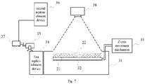
- Fig. 6 shows a structure diagram of another 3D printing apparatus of the present application.
- the forming chamber 31, the build platform 32, the Z-axis movement mechanism 33, the first replenishment device 34, the first coating device 35, the second replenishment device 36, and the second coating device 37 shown in Fig. 6 can all be implemented by using the forming chamber 11, the build platform 12, the Z-axis movement mechanism 13, the first replenishment device 14, the first coating device 15, the second replenishment device 16, and the second coating device 17 shown in Fig. 1 and structures provided in the corresponding description.
- the first coating device 35 coats the first material 21 before the second coating device 37.
- the optical system 38 shown in Fig. 7 includes a light source that irradiates the area-to-be-formed to cure a photocurable resin coated to the area-to-be-formed according to the sliced pattern.
- the first material is a viscous material formed by mixing a ceramic component and a solvent
- the second material includes a mixed liquid of the photocurable resin and the pigment.
- the light source radiates the entire area-to-be-formed without interruption, or radiates the entire area-to-be-formed during coating by the second coating device, or radiates the entire area-to-be-formed after a preset delay after the second material is sprayed onto the first material.
- the light source includes any light source capable of providing energy for curing the photocurable resin, including, but not limited to, an optical system capable of radiating energy in a patterning manner, and an optical system incapable of radiating energy in a patterning manner.
- the light source is an LED array, a laser arrays, or the like.
- the 3D printing apparatus coats the area-to-be-formed with the first material before spraying the second material.
- a control device in the 3D printing apparatus sprays the second material based on the position of the second coating device in the area-to-be-formed and the current sliced pattern.
- Fig. 8 shows a flow diagram of manufacturing a cross-section cured layer of the dental restoration blank by the control device in the 3D printing apparatus.
- the control device controls the Z-axis movement mechanism to cause the build platform to move toward the interior of the cavity by executing step S210, and controls the first replenishment device to push a preset volume of the first material out of the first replenishment device and controls the first coating device to coat the area-to-be-formed with the first material by executing step S221.
- Steps S210 and S221 are same as or similar to steps S110and S121 in Fig. 5 , and will not be described in detail here.
- control device then executes step S222: coating the area-to-be-formed with the second material based on a sliced pattern of the dental restoration blank to be formed.
- color data corresponding to a sliced pattern of each layer in the dental restoration model is unified, and the control device controls, according to the color data corresponding to the current sliced pattern to be manufactured, the second replenishment device to export the corresponding second material, and controls, according to the current sliced pattern to be manufactured, the second coating device to spray the exported second material into an area of a corresponding shape in the area-to-be-formed.
- the first coating device included in the 3D printing apparatus is a recoater assembly and the second coating device included therein includes a nozzle unit as an example, in conjunction with Fig. 7 , the nozzle unit may be arranged on a mounting beam of the recoater assembly and sprays the second material 22 after a scraper body coats the first material 21.
- the control device controls the first replenishment device 34 to push a preset volume of the first material 21 out of the first replenishment device 34 and controls the first coating device 35 to coat the area-to-be-formed with the first material 21; and during coating of the first material, based on the position of the nozzle unit moved with the scraper body in the-area-to-be-formed, an area of a shape corresponding to the sliced pattern to be manufactured in the area-to-be-formed, and the color data corresponding to the current sliced pattern to be manufactured, the control device controls the second coating device 37 to spray the exported corresponding second material 22 into the area of the shape.
- color data corresponding to the sliced pattern of each layer in the dental restoration model includes color distribution data.
- the color data describes second material numbers that change from pixel points of the outer contour of the sliced pattern toward pixel points in a central area.
- the control device controls, according to the color distribution data corresponding to the current sliced pattern to be manufactured, the second replenishment device to export second materials with different numbers to spray hole rows in the nozzle unit and controls, according to the current sliced pattern to be manufactured, the second coating device to spray the exported second materials into an area of a corresponding shape in the area-to-be-formed.
- the first coating device included in the 3D printing apparatus is a recoater assembly and the second coating device included therein includes a nozzle unit as an example
- the nozzle unit may be arranged on a mounting beam of the recoater assembly and sprays the second materials after a scraper body coats the first material.
- the control device controls the first replenishment device to push a preset volume of the first material out of the first replenishment device and controls the first coating device to coat the area-to-be-formed with the first material; and during coating of the first material, based on the position of the nozzle unit moved with the scraper body in the-area-to-be-formed, an area of a shape corresponding to the sliced pattern to be manufactured in the area-to-be-formed, and the color distribution data corresponding to the current sliced pattern to be manufactured (as shown in Fig. 2 ), the control device controls the second coating device to spray the exported multiple second materials into the area of the shape.
- control device further executes step S240.
- control device may execute step S230 below before step S240 to cure the photocurable resin in the area coated with the second material and to form a cross-section cured layer of the dental restoration blank by curing the photocurable resin.
- Step S230 is same as or similar to step S130, and will not be described in detail here.
- the control device performs step S240 after a delay of a preset period of time.
- step S240 the control device radiates the-area-to-be-formed. For example, if the control device controls an LED array to irradiate the entire area-to-be-formed, the second material sprayed based on the sliced pattern is cured into a cross-section cured layer of the dental restoration blank due to containing a photocurable resin, while an area only coated with the first material in the area-to-be-formed remains in a viscous liquid state on the build platform and is not cured as it does not contain a photocurable resin.
- the 3D printing apparatus further includes an environmental regulation system configured to regulate environmental parameters of a material layer to be formed.
- the environmental regulation system includes at least some or all of a heating component, a temperature sensing component, an air pressure sensing component, a gas sensing component, a temperature control component, an air pressure control component, etc.
- Front-end controlled components such as the heating component, the temperature sensing component and the air pressure sensing component, and data collection components may be distributed in the forming chamber, the optical system, the first coating device, the first replenishment device, the second coating device, and the second replenishment device.
- the heating component may be arranged within the cavity of the forming chamber or on the build platform, the temperature sensing component may be arranged on the cavity or the recoater assembly, and the air pressure sensing component and the gas sensing component may be arranged within the cavity.
- Back-end control components such as the temperature control component and the air pressure control component may be integrated into the control device, or provided separately and connected to the control device.
- the control device monitors environmental data provided by sensing components such as the temperature sensing component and the air pressure sensing component throughout the manufacturing process of the dental restoration blank, and controls the heating component, the air pressure control component and the like based on the environmental data so that the environment in the forming chamber is conducive to manufacturing the dental restoration blank using the first material and the second material.
- the dental restoration blank manufactured by any method described above has a uniform distribution effect in terms of color and transmittance, and the 3D printing apparatus in the present application improves the manufacturing efficiency of the dental restoration blank compared to conventional 3D manufacturing means due to the addition of colors to the curing process of each layer of the dental restoration blank.
- the manufactured dental restoration blank is further at least processed as follows to obtain a dental replacement physical object.
- a technician performs degreasing, sintering, glazing, polishing and other treatments on the dental restoration blank taken from the 3D printing apparatus.
- the object is a mixture of organic and inorganic materials, and then the organic materials need to be removed first, which is degreasing.
- the object shrinks by a certain ratio (about 20%), and the original spaces of the organic components are filled to obtain a shrunken pure ceramic part; then the shrunken dental restoration blank is sintered such that the blank is sintered into a crystallized part; after sintering, the technician also needs to confirm dimensions and manually adjust them if they are not suitable; afterwards, surface treatments such as polishing and glazing are performed, to obtain a dental replacement physical object with suitable gloss and roughness.
- the original model of the dental restoration needs to be amplified in the transverse, longitudinal and height directions according to the shrinkage ratios in the subsequent steps such as greasing and sintering and component ratios in the first and second materials used therein. Furthermore, depending on the shape of the dental restoration to be manufactured, the printing sequence, etc., it is also needs to design a support model for the original model of the dental restoration in some shapes.
- the support structure and a main body of the physical object are connected into a whole.
- a technician clips and polishes the support structure.
- the manufactured blank due to different color distribution from outside to inside, the manufactured blank also needs degreasing, sintering and other operations so that the main body of the dental restoration is compact, and therefore the existing support structure removal operation is prone to damage the main body of the dental restoration blank, thereby reducing the finished product qualification rate.
- the present application also provides an image processing method for constructing a support model.
- the image processing method is mainly executed by a computer device.
- the computer device at least includes a storage unit, a processing unit, and a data interface unit.
- the storage unit is configured to store an original model of a dental restoration to be layered and at least one program.
- the storage unit may include a high speed random access memory, and may also include a non-volatile memory, such as one or more magnetic disk storage devices, flash memory devices, or other non-volatile solid state storage devices.
- the storage unit may also include a memory remote from one or more processors, such as a network attached storage accessed via RF circuit or external port and a communication network (not shown), wherein the communication network may be the Internet, one or multiple intranets, local area networks (LANs), wide area networks (WLANs), storage area networks (SANs), etc., or a suitable combination thereof.
- a memory controller may control access to the storage unit by other components of the computer device, such as the processing unit and the data interface unit.
- the processing unit is configured to execute at least one program stored in the storage unit to construct a support model of the stored original model of the dental restoration.
- the processing unit is operatively coupled with the high-speed storage unit. More specifically, the processing unit may execute the program in the storage unit to perform operations in the computer device.
- the processing unit may include one or more general purpose microprocessors, one or more dedicated processors (ASICs), one or more field programmable logic arrays (FPGAs), or any combination thereof.
- the processing unit is operatively coupled with a network interface to communicatively couple the computer device to a network.
- the network interface may connect the computer device to a personal area network (PAN) (such as a Bluetooth network), a local area network (LAN) (such as an 802.11x Wi-Fi network), and/or a wide area network (WAN) (injected into a 4G or LTE cellular network).
- PAN personal area network
- LAN local area network
- WAN wide area network
- the processing unit is also operatively coupled with an I/O port and an input structure, wherein the I/O port enables the computer device to interact with various other electronic devices, and the input structure enables a user to interact with the computer device.
- the input structure may include a button, a keyboard, a mouse, a touchpad, etc.
- an electronic display may include a touch component that facilitates a user input by detecting the occurrence and/or location of touching its screen (such as a surface of the electronic display 12) by an object.
- the above-mentioned network interface, I/O port and input structure are used as examples of the data interface unit.
- the original model of the dental storage stored in the storage unit may be received via any of the data interface units and is stored in the storage unit via a read/write operation of the processing unit.
- the original model of the dental restoration stored in the storage unit is constructed based on oral image data received by any of the data interface units.
- the processing unit constructs the original model of the dental restoration to be manufactured based on the oral image data.
- the processing unit amplifies the original model based on a preset scale.
- the preset scale may include respective magnification ratios in the transverse, longitudinal and height directions of the dental restoration blank.
- the preset scale is a magnification ratio determined based on maximum values of the shrinkage ratios of the dental restoration blank in the transverse, longitudinal and height directions during the subsequent treatments on the dental restoration blank.
- the processing unit saves the amplified original model of the dental restoration in the storage unit for retrieval during the execution of an image processing method described below.
- Fig. 9 shows a flow diagram of an image processing method for designing a support model based on an original model of a dental restoration.
- the processing unit of the computer device calls at least one program to execute the following steps to achieve the purpose of constructing a support model for the original model of the dental restoration.
- step S310 constructing a support model for an original model of a dental restoration.
- the computer device may construct the support model according to an initial placement posture of the original model of the dental restoration.
- the initial placement posture refers to the placement angle and placement position when the original model of the dental restoration is imported.
- the original model of the dental restoration is usually placed vertically with the root facing downward and the crown facing upward, and the computer device constructs the support model according to the above-mentioned placement posture.
- a plurality of original models of dental restorations are selected, and support models corresponding to the plurality of original models of dental restorations are constructed.
- the placement postures of the original models of dental restorations are adjusted, for example, in accordance with at least one of the conditions: the heights of the original models of dental restorations are substantially same, and the number of the placed original models of dental restorations is maximized, and the computer device constructs the support models based on the dental restoration models after adjustment of printing postures.
- the support model may include a base portion and a support portion, wherein the base portion may be a plate-like structure, and the support portion is a multi-column, net-like or other structure.
- the support model accommodates the original model of the dental restoration.
- Fig. 10 which shows a shape diagram of the support model 42 and the original model 41 of the dental restoration
- the support portion of the support model 42 is configured to be a bowl-like structure based on the outer contour of the original model 41 of the dental restoration.
- the support model constructed by the computer device may define a connection boundary with the outer contour of the original model of the dental restoration by point connection, line connection or surface connection. There is a gap between the connection boundary of the support model and the outer contour of the original model of the dental restoration.
- a three-dimensional model containing the support model and the original model of the dental restoration is called a dental restoration model.
- step S320 performing layering processing on the dental restoration model, wherein in a sliced pattern corresponding to a same cross-section layer, there is a gap between a sliced area of the support model and a sliced area of the original model of the dental restoration.
- the computer device performs layering processing on the dental restoration model according to preset layer heights.
- the layer heights may be set uniformly.
- the layered heights may also be differentiated according to whether the dental restoration model contains a cross-section of the original model of the dental restoration.
- a layer height set for a layer that only contains the support model as a part of the dental restoration model may be greater than a layer height for a layer that contains the original model of the dental restoration.
- the computer device first performs layering processing on a support model part at the bottom of the dental restoration model based on a first layer height according to a printing sequence, and determines whether an upper surface of a cross-section layer obtained by the layering contains a sliced area of the original model of the dental restoration.
- the upper surface does not contain a sliced area of the original model of the dental restoration, it continues the layering processing based on the first layer height. If the upper surface contains a sliced area of the original model of the dental restoration, it performs layering processing again on the cross-section layer containing the sliced area of the original model of the dental restoration based on a second layer height, and performs layering processing on the subsequent part of the dental restoration model based on the second layer height.
- the computer device based on an upper and/or lower surface of each cross-section layer obtained by the layering, also determines a sliced pattern of the cross-section layer. For example, if the computer device assumes, by default, that a cross-section layer obtained by the layering has identical upper and lower surfaces, it uniformly determines the upper or lower surface of the cross-section layer as a sliced pattern of the corresponding cross-section layer. In the case where a sliced pattern of a same layer contains both the support model and a cross-section layer of the original model of the dental restoration, there is a gap between a sliced area of the support model and a sliced area of the original model of the dental restoration in the corresponding sliced pattern.
- the computer device also determines color data of sliced patterns of layers in the original model of the dental restoration according to tooth color information in acquired oral image data.
- the computer device assigns values to the color data of the layers in the original model of the dental restoration based on the tooth color information in the oral image data according to a preset color standard.
- the color standard includes, but is not limited to: VITA colorimetric card, custom color card standards, etc.
- one or more color card numbers are determined according to the VITA colorimetric card from positions corresponding to the layers of the original model of the dental restoration in the oral image data, and the determined one or more color card numbers are assigned to all pixel points of the sliced patterns in the corresponding layers.
- the computer device determines color data of the outer contours of the sliced patterns of the layers of the original model according to positions corresponding to the layers in the oral image data; and determines color distribution data of pixel points in the sliced patterns from the outer contours inward based on a preset color change condition.
- the color change condition is related to the position of the constructed original model of the dental restoration in the oral cavity, the transparency of the tooth, and the change properties of colors.
- the computer device can also determine color data of the support model according to the determined color data of the outer contours of the sliced patterns of the layers of the original model so as to manufacture a dental restoration blank with a support using the 3D printing apparatus and materials shown in Fig. 1 or 7 .
- the computer device saves the dental restoration model after layering and color processing in a file.
- a technician can import the file into the 3D printing apparatus.
- the 3D printing apparatus can manufacture a dental restoration blank including a support based on any of the above structures and the matching manufacturing method.
- the optical system of the 3D printing apparatus irradiates the area-to-be-formed based on a sliced pattern containing a sliced area of the support model and a sliced area of the original model, resulting in an uncured filling material between a cross-section cured layer of a cured support and the cross-section cured layer of the dental restoration blank.
- the filling material may include only the first material, or include both the first material and the second material, depending on the control device's control of the material coated by the first coating device and the second coating device.
- the filling material contains the viscous material of the first material
- the manufactured support restricts the flow of the viscous material
- the support effectively supports the shape of the manufactured dental restoration blank through the filling material; and as the uncured filling material is between the manufactured dental restoration blank and the support, the support does not need to be removed from the dental restoration blank.
Landscapes
- Engineering & Computer Science (AREA)
- Chemical & Material Sciences (AREA)
- Materials Engineering (AREA)
- Manufacturing & Machinery (AREA)
- Physics & Mathematics (AREA)
- Mechanical Engineering (AREA)
- Optics & Photonics (AREA)
- Health & Medical Sciences (AREA)
- Toxicology (AREA)
- Epidemiology (AREA)
- Oral & Maxillofacial Surgery (AREA)
- Life Sciences & Earth Sciences (AREA)
- Animal Behavior & Ethology (AREA)
- General Health & Medical Sciences (AREA)
- Public Health (AREA)
- Veterinary Medicine (AREA)
- Dentistry (AREA)
- Ceramic Engineering (AREA)
- Composite Materials (AREA)
- Structural Engineering (AREA)
- Civil Engineering (AREA)
- Environmental & Geological Engineering (AREA)
- Dental Prosthetics (AREA)
Applications Claiming Priority (2)
| Application Number | Priority Date | Filing Date | Title |
|---|---|---|---|
| CN201910705232.XA CN110480792B (zh) | 2019-08-01 | 2019-08-01 | 制造方法、系统、3d打印设备及图像处理方法 |
| PCT/CN2020/103151 WO2021017937A1 (fr) | 2019-08-01 | 2020-07-21 | Procédé et système de fabrication, appareil d'impression 3d et procédé de traitement d'image |
Publications (2)
| Publication Number | Publication Date |
|---|---|
| EP4008524A1 true EP4008524A1 (fr) | 2022-06-08 |
| EP4008524A4 EP4008524A4 (fr) | 2023-11-22 |
Family
ID=68548995
Family Applications (1)
| Application Number | Title | Priority Date | Filing Date |
|---|---|---|---|
| EP20846232.5A Pending EP4008524A4 (fr) | 2019-08-01 | 2020-07-21 | Procédé et système de fabrication, appareil d'impression 3d et procédé de traitement d'image |
Country Status (4)
| Country | Link |
|---|---|
| US (1) | US20220281162A1 (fr) |
| EP (1) | EP4008524A4 (fr) |
| CN (2) | CN110480792B (fr) |
| WO (1) | WO2021017937A1 (fr) |
Families Citing this family (14)
| Publication number | Priority date | Publication date | Assignee | Title |
|---|---|---|---|---|
| CN110480792B (zh) * | 2019-08-01 | 2021-07-06 | 苏州铼赛智能科技有限公司 | 制造方法、系统、3d打印设备及图像处理方法 |
| CN113431301B (zh) * | 2020-03-20 | 2022-04-12 | 广东博智林机器人有限公司 | 一种喷涂路径确定方法、装置、电子设备及存储介质 |
| TWI759992B (zh) * | 2020-12-07 | 2022-04-01 | 法藍瓷股份有限公司 | 陶瓷牙冠之三維積層暨成色設備及其方法 |
| CN112836371B (zh) * | 2021-02-05 | 2024-08-09 | 中国人民解放军空军军医大学 | 牙科修复体的实际收缩率的测算方法 |
| CN113185283A (zh) * | 2021-06-11 | 2021-07-30 | 杭州普太科技有限公司 | 正畸氧化锆托槽的制备方法 |
| CN113393584B (zh) * | 2021-06-16 | 2023-07-14 | 深圳市汉森软件有限公司 | 三维模型的色彩处理方法、装置、设备及存储介质 |
| US12036743B2 (en) | 2021-07-16 | 2024-07-16 | Hirsch Dynamics Holding Ag | Method for manufacturing an object, in particular an orthodontic appliance, by a 3D-printing device |
| US11771534B2 (en) * | 2021-12-22 | 2023-10-03 | Franz Collection Inc. | Apparatus and method for three-dimensional laminating a ceramic denture in a color-and-transmittance variable manner |
| CN116330428A (zh) * | 2021-12-22 | 2023-06-27 | 法蓝瓷股份有限公司 | 可调成色和透光的陶瓷义齿的三维积层设备及方法 |
| US11839916B2 (en) * | 2022-01-20 | 2023-12-12 | Additive Technologies Llc | Device and method for cleaning an orifice in a metal drop ejecting three-dimensional (3D) metal object |
| CN115446948A (zh) * | 2022-08-19 | 2022-12-09 | 康硕(德阳)智能制造有限公司 | 一种基于半固化支撑的光固化成型陶瓷3d打印方法 |
| CN116310257B (zh) * | 2023-03-21 | 2025-12-23 | 深圳云甲科技有限公司 | 修复体设计可视化方法、装置、计算设备及可读存储介质 |
| CN116655358A (zh) * | 2023-06-16 | 2023-08-29 | 江西金石三维智能制造科技有限公司 | 一种dlp用氧化铝微结构件材料及其制备方法 |
| CN119952075A (zh) * | 2025-02-18 | 2025-05-09 | 合肥工业大学 | 一种多材料激光粉末床增材制造铺粉方法及铺粉装置 |
Family Cites Families (14)
| Publication number | Priority date | Publication date | Assignee | Title |
|---|---|---|---|---|
| US5104592A (en) * | 1988-04-18 | 1992-04-14 | 3D Systems, Inc. | Method of and apparatus for production of three-dimensional objects by stereolithography with reduced curl |
| GB0112675D0 (en) * | 2001-05-24 | 2001-07-18 | Vantico Ltd | Three-dimensional structured printing |
| CN104619477B (zh) * | 2012-06-01 | 2017-11-03 | 3M创新有限公司 | 制备定制的牙体坯料的方法和系统 |
| EP3294530B1 (fr) * | 2015-05-15 | 2021-10-27 | Dentsply Sirona Inc. | Procédé de fabrication en trois dimensions pour production rapide d'objets |
| CN105415688B (zh) * | 2015-12-22 | 2017-10-20 | 珠海天威飞马打印耗材有限公司 | 三维打印机和三维打印方法 |
| US20170251713A1 (en) * | 2016-03-07 | 2017-09-07 | Telamens, Inc. | 3d printer and method for printing an object using a curable liquid |
| EP3235467B1 (fr) * | 2016-04-22 | 2021-03-31 | Ivoclar Vivadent AG | Méthode de fabrication d'une restauration dentaire |
| JP2017202046A (ja) * | 2016-05-10 | 2017-11-16 | 株式会社リコー | 立体造形材料セット、立体造形物の製造方法、及び立体造形物の製造装置 |
| CN106217882B (zh) * | 2016-08-19 | 2019-03-15 | 上海联泰科技股份有限公司 | 适用于光固化成型的3d打印陶瓷义齿的方法和装置 |
| CN106393662B (zh) * | 2016-11-30 | 2019-11-26 | 深圳市七号科技有限公司 | 一种全彩色3d打印的装置和方法 |
| CN107139456B (zh) * | 2017-05-17 | 2019-08-20 | 上海联泰科技股份有限公司 | 三维物体数据的分层方法、3d打印方法及设备 |
| CN108582767B (zh) * | 2018-03-30 | 2020-10-16 | 无锡映型三维数字技术有限公司 | 一种无支撑的3d打印方法 |
| CN109130174A (zh) * | 2018-08-17 | 2019-01-04 | 上海联泰科技股份有限公司 | 光学系统、控制方法及系统、3d打印设备 |
| CN110480792B (zh) * | 2019-08-01 | 2021-07-06 | 苏州铼赛智能科技有限公司 | 制造方法、系统、3d打印设备及图像处理方法 |
-
2019
- 2019-08-01 CN CN201910705232.XA patent/CN110480792B/zh active Active
- 2019-08-01 CN CN202110671087.5A patent/CN113306145B/zh active Active
-
2020
- 2020-07-21 US US17/631,859 patent/US20220281162A1/en not_active Abandoned
- 2020-07-21 EP EP20846232.5A patent/EP4008524A4/fr active Pending
- 2020-07-21 WO PCT/CN2020/103151 patent/WO2021017937A1/fr not_active Ceased
Also Published As
| Publication number | Publication date |
|---|---|
| EP4008524A4 (fr) | 2023-11-22 |
| CN110480792B (zh) | 2021-07-06 |
| CN113306145B (zh) | 2023-01-24 |
| CN110480792A (zh) | 2019-11-22 |
| US20220281162A1 (en) | 2022-09-08 |
| CN113306145A (zh) | 2021-08-27 |
| WO2021017937A1 (fr) | 2021-02-04 |
Similar Documents
| Publication | Publication Date | Title |
|---|---|---|
| EP4008524A1 (fr) | Procédé et système de fabrication, appareil d'impression 3d et procédé de traitement d'image | |
| CN109641385B (zh) | 适用于光固化成型的3d打印陶瓷义齿的方法和装置 | |
| US11577453B2 (en) | Additive manufacturing system and a method of additive manufacturing | |
| US10849724B2 (en) | High strength three dimensional fabricating material systems and methods for producing dental products | |
| EP3658303B1 (fr) | Procédé de fabrication d'un objet physique par fabrication d'additifs | |
| US10299896B2 (en) | Three-dimensional fabricating material systems and methods for producing layered dental products | |
| EP2643148B1 (fr) | Système et procédé pour fabrication additive d'un objet | |
| EP3626429B1 (fr) | Procédé de mise en couches de données d'objet en trois dimensions, et procédé et dispositif d'impression 3d | |
| DE102007010624A1 (de) | Vorrichtung zur schichtweisen generativen Herstellung dreidimensionaler Formteile, Verfahren zur Herstellung dieser Formteile sowie diese Formteile | |
| EP3493764B1 (fr) | Dispositif et procédé permettant de construire progressivement un objet à partir d'un matériau durcissable à la lumière | |
| EP3373845B1 (fr) | Procédé et système permettant de construire un objet physique solide | |
| EP3870100B1 (fr) | Précurseur de couronne dentaire composite imprimé en 3d équipé d'un élément de support et procédé de production | |
| JP2004344623A (ja) | 歯科用構造物自動作製装置 | |
| CA3029491C (fr) | Systemes de materiaux de fabrication en trois dimensions de haute resistance et procedes de production de produits dentaires |
Legal Events
| Date | Code | Title | Description |
|---|---|---|---|
| STAA | Information on the status of an ep patent application or granted ep patent |
Free format text: STATUS: THE INTERNATIONAL PUBLICATION HAS BEEN MADE |
|
| PUAI | Public reference made under article 153(3) epc to a published international application that has entered the european phase |
Free format text: ORIGINAL CODE: 0009012 |
|
| STAA | Information on the status of an ep patent application or granted ep patent |
Free format text: STATUS: REQUEST FOR EXAMINATION WAS MADE |
|
| 17P | Request for examination filed |
Effective date: 20220125 |
|
| AK | Designated contracting states |
Kind code of ref document: A1 Designated state(s): AL AT BE BG CH CY CZ DE DK EE ES FI FR GB GR HR HU IE IS IT LI LT LU LV MC MK MT NL NO PL PT RO RS SE SI SK SM TR |
|
| DAV | Request for validation of the european patent (deleted) | ||
| DAX | Request for extension of the european patent (deleted) | ||
| RIN1 | Information on inventor provided before grant (corrected) |
Inventor name: LIU, ZHEN |
|
| REG | Reference to a national code |
Ref country code: DE Ref legal event code: R079 Free format text: PREVIOUS MAIN CLASS: B29C0064124000 Ipc: B29C0064336000 |
|
| RIC1 | Information provided on ipc code assigned before grant |
Ipc: B33Y 50/00 20150101ALI20230712BHEP Ipc: B33Y 40/00 20200101ALI20230712BHEP Ipc: B29C 64/386 20170101ALI20230712BHEP Ipc: B29C 64/364 20170101ALI20230712BHEP Ipc: A61C 13/08 20060101ALI20230712BHEP Ipc: A61C 13/00 20060101ALI20230712BHEP Ipc: B29C 64/40 20170101ALI20230712BHEP Ipc: B28B 1/00 20060101ALI20230712BHEP Ipc: B33Y 30/00 20150101ALI20230712BHEP Ipc: B33Y 10/00 20150101ALI20230712BHEP Ipc: B29C 67/00 20170101ALI20230712BHEP Ipc: B29C 64/393 20170101ALI20230712BHEP Ipc: B29C 64/124 20170101ALI20230712BHEP Ipc: B29C 64/336 20170101AFI20230712BHEP |
|
| A4 | Supplementary search report drawn up and despatched |
Effective date: 20231024 |
|
| RIC1 | Information provided on ipc code assigned before grant |
Ipc: B33Y 50/00 20150101ALI20231018BHEP Ipc: B33Y 40/00 20200101ALI20231018BHEP Ipc: B29C 64/386 20170101ALI20231018BHEP Ipc: B29C 64/364 20170101ALI20231018BHEP Ipc: A61C 13/08 20060101ALI20231018BHEP Ipc: A61C 13/00 20060101ALI20231018BHEP Ipc: B29C 64/40 20170101ALI20231018BHEP Ipc: B28B 1/00 20060101ALI20231018BHEP Ipc: B33Y 30/00 20150101ALI20231018BHEP Ipc: B33Y 10/00 20150101ALI20231018BHEP Ipc: B29C 67/00 20170101ALI20231018BHEP Ipc: B29C 64/393 20170101ALI20231018BHEP Ipc: B29C 64/124 20170101ALI20231018BHEP Ipc: B29C 64/336 20170101AFI20231018BHEP |
|
| STAA | Information on the status of an ep patent application or granted ep patent |
Free format text: STATUS: EXAMINATION IS IN PROGRESS |
|
| 17Q | First examination report despatched |
Effective date: 20250922 |