EP4008573A1 - Lüftungs-, heizungs- und/oder klimaanlage eines kraftfahrzeugs - Google Patents
Lüftungs-, heizungs- und/oder klimaanlage eines kraftfahrzeugs Download PDFInfo
- Publication number
- EP4008573A1 EP4008573A1 EP20211130.8A EP20211130A EP4008573A1 EP 4008573 A1 EP4008573 A1 EP 4008573A1 EP 20211130 A EP20211130 A EP 20211130A EP 4008573 A1 EP4008573 A1 EP 4008573A1
- Authority
- EP
- European Patent Office
- Prior art keywords
- casing
- groove
- rib
- ventilation
- ventilation system
- Prior art date
- Legal status (The legal status is an assumption and is not a legal conclusion. Google has not performed a legal analysis and makes no representation as to the accuracy of the status listed.)
- Granted
Links
Images


Classifications
-
- B—PERFORMING OPERATIONS; TRANSPORTING
- B60—VEHICLES IN GENERAL
- B60H—ARRANGEMENTS OF HEATING, COOLING, VENTILATING OR OTHER AIR-TREATING DEVICES SPECIALLY ADAPTED FOR PASSENGER OR GOODS SPACES OF VEHICLES
- B60H1/00—Heating, cooling or ventilating devices
- B60H1/00457—Ventilation unit, e.g. combined with a radiator
- B60H1/00471—The ventilator being of the radial type, i.e. with radial expulsion of the air
-
- B—PERFORMING OPERATIONS; TRANSPORTING
- B60—VEHICLES IN GENERAL
- B60H—ARRANGEMENTS OF HEATING, COOLING, VENTILATING OR OTHER AIR-TREATING DEVICES SPECIALLY ADAPTED FOR PASSENGER OR GOODS SPACES OF VEHICLES
- B60H1/00—Heating, cooling or ventilating devices
- B60H1/00507—Details, e.g. mounting arrangements, desaeration devices
- B60H1/00514—Details of air conditioning housings
- B60H1/00528—Connections between housing parts
-
- F—MECHANICAL ENGINEERING; LIGHTING; HEATING; WEAPONS; BLASTING
- F04—POSITIVE - DISPLACEMENT MACHINES FOR LIQUIDS; PUMPS FOR LIQUIDS OR ELASTIC FLUIDS
- F04D—NON-POSITIVE-DISPLACEMENT PUMPS
- F04D29/00—Details, component parts, or accessories
- F04D29/08—Sealings
- F04D29/083—Sealings especially adapted for elastic fluid pumps
-
- F—MECHANICAL ENGINEERING; LIGHTING; HEATING; WEAPONS; BLASTING
- F16—ENGINEERING ELEMENTS AND UNITS; GENERAL MEASURES FOR PRODUCING AND MAINTAINING EFFECTIVE FUNCTIONING OF MACHINES OR INSTALLATIONS; THERMAL INSULATION IN GENERAL
- F16J—PISTONS; CYLINDERS; SEALINGS
- F16J15/00—Sealings
- F16J15/02—Sealings between relatively-stationary surfaces
- F16J15/06—Sealings between relatively-stationary surfaces with solid packing compressed between sealing surfaces
- F16J15/062—Sealings between relatively-stationary surfaces with solid packing compressed between sealing surfaces characterised by the geometry of the seat
-
- F—MECHANICAL ENGINEERING; LIGHTING; HEATING; WEAPONS; BLASTING
- F16—ENGINEERING ELEMENTS AND UNITS; GENERAL MEASURES FOR PRODUCING AND MAINTAINING EFFECTIVE FUNCTIONING OF MACHINES OR INSTALLATIONS; THERMAL INSULATION IN GENERAL
- F16J—PISTONS; CYLINDERS; SEALINGS
- F16J15/00—Sealings
- F16J15/02—Sealings between relatively-stationary surfaces
- F16J15/06—Sealings between relatively-stationary surfaces with solid packing compressed between sealing surfaces
- F16J15/10—Sealings between relatively-stationary surfaces with solid packing compressed between sealing surfaces with non-metallic packing
- F16J15/104—Sealings between relatively-stationary surfaces with solid packing compressed between sealing surfaces with non-metallic packing characterised by structure
- F16J15/106—Sealings between relatively-stationary surfaces with solid packing compressed between sealing surfaces with non-metallic packing characterised by structure homogeneous
-
- B—PERFORMING OPERATIONS; TRANSPORTING
- B60—VEHICLES IN GENERAL
- B60H—ARRANGEMENTS OF HEATING, COOLING, VENTILATING OR OTHER AIR-TREATING DEVICES SPECIALLY ADAPTED FOR PASSENGER OR GOODS SPACES OF VEHICLES
- B60H1/00—Heating, cooling or ventilating devices
- B60H1/00507—Details, e.g. mounting arrangements, desaeration devices
- B60H2001/00635—Air-tight sealing devices
-
- F—MECHANICAL ENGINEERING; LIGHTING; HEATING; WEAPONS; BLASTING
- F04—POSITIVE - DISPLACEMENT MACHINES FOR LIQUIDS; PUMPS FOR LIQUIDS OR ELASTIC FLUIDS
- F04D—NON-POSITIVE-DISPLACEMENT PUMPS
- F04D29/00—Details, component parts, or accessories
- F04D29/40—Casings; Connections of working fluid
- F04D29/42—Casings; Connections of working fluid for radial or helico-centrifugal pumps
- F04D29/4206—Casings; Connections of working fluid for radial or helico-centrifugal pumps especially adapted for elastic fluid pumps
- F04D29/4226—Fan casings
Definitions
- the present invention falls within the field of ventilation, heating and/or air conditioning systems for a motor vehicle, and more particularly of a device for sealing such a ventilation, heating and/or air conditioning system. or air conditioning.
- the domain extends to any component or volume of such a vehicle, or even to any domain in which one of the components needs to be heat treated.
- the ventilation, heating and/or air conditioning systems which are fitted to motor vehicles allow the users of the vehicle to control a supply of cold air or hot air in different zones of the vehicle, in particular its passenger compartment or its batteries.
- Such ventilation, heating and/or air conditioning systems generally comprise a ventilation member and several elements ensuring the cooling and/or heating of a flow of air circulated by the ventilation member. The user of the motor vehicle can thus choose to cool or heat the air circulated by the ventilation member to increase or decrease the temperature within the passenger compartment or the component.
- the ventilation member comprises a casing in two parts cooperating with each other in order to delimit an internal volume of the ventilation, heating and/or air conditioning system. conditioned. Generally, it is in this internal volume that the ventilation member is placed.
- the ventilation, heating and/or air conditioning system comprises a sealing device making the internal volume sealed against the external environment of the casing at least at the level of the connection between the two parts of the casing.
- this sealing device is formed by cooperation between a groove arranged on one of the two constituent parts of the casing, a rib arranged on the other constituent part of the casing and a sealing element, such as a gasket , arranged in the bottom of the groove for example.
- such a sealing device requires a sealing member in addition to the cooperation between the groove and the rib in order to seal the internal volume.
- This additional element adds a step during the assembly of the ventilation, heating and/or air conditioning system, resulting in additional cost and time during the assembly of such a system.
- the present invention is an improvement of the already existing solutions and proposes a casing whose tightness ensured by the sealing device is achieved solely thanks to the cooperation between the rib and the groove, without the need to add a additional item, such as a gasket.
- the main object of the present invention is thus a ventilation system comprising at least a first casing and a second casing cooperating with the first casing to delimit an internal volume of the ventilation system, the latter comprising at least a sealing device between the first casing and the second casing, at least one of the casings comprises a wall having a peripheral edge which delimits at least one constituent groove of the device sealing, characterized in that the peripheral edge comprises at least one boss extending towards the inside of the groove.
- the groove is constitutive of the sealing device and is configured to cooperate with a rib in order to ensure sealing between the internal volume delimited by the casings and the external environment of the ventilation, heating and/or air conditioning system .
- the groove is a groove made at the peripheral edge of the casing, this groove extending peripherally along this edge.
- the sealing device is very particularly suitable for sealing against liquids.
- boss refers to a projection, of advantageously curved shape, reducing a width of the groove, this dimension being measured along a direction perpendicular to the main extension plane of the wall having the peripheral edge.
- the peripheral edge comprises a first boss and a second boss extending towards the inside of the groove, one in the direction of the other.
- the groove is delimited by two bearing flanks carrying the first and the second bosses.
- the latter each project from these support flanks one in the direction of the other.
- they are both arranged at an identical, or substantially identical, distance from a bottom of the groove.
- the first casing comprises the groove while the second casing comprises a wall having a peripheral side from which projects a rib configured to be housed in the groove of the first casing.
- the rib also constitutes the sealing device and comprises an internal contact face oriented towards the internal volume delimited by the boxes and an external contact face oriented towards the external environment of the ventilation, heating and/or air conditioning system.
- the contact faces are in contact with the bosses of the groove when the boxes cooperate with each other.
- the rib at least partially comprises an elastically deformable material.
- “Elastically deformable” means a material configured to deform in the elastic range of the material. This deformability of the material which covers or which constitutes at least partially the rib allows the material compressed by the boss(es) to move into an upper part of the groove located above the boss(es).
- the elastically deformable material is for example a synthetic rubber, of the ethylene-propylene-diene monomer (EPDM) type or of the acrylic nitrile butadiene (NBR) type, this list not being exhaustive.
- EPDM ethylene-propylene-diene monomer
- NBR acrylic nitrile butadiene
- the rib comprises at least one teat resulting from material with the second casing, the material of the second casing having a Young's modulus greater than that of the elastically deformable material.
- the teat has the function of providing a certain rigidity to the rib, thus helping to maintain the shape of the rib.
- the teat, as well as advantageously the first and second casings, are mainly composed of polyamide (PA66) which can be reinforced with 30 to 60% glass fibers (GF30 or GF60).
- the pacifier has a deformation threshold, which corresponds to a force value from which the material is likely to deform, this deformation threshold of the material constituting the pacifier being greater than that of the elastically deformable material of the rib. In other words, a greater force will be required to deform the pacifier compared to the force required to deform the elastically deformable material, all other things being equal.
- the rib is entirely composed of an elastically deformable material.
- the whole of the rib is composed of elastically deformable material, this elastically deformable material thus extending from the peripheral flank to the end of the rib.
- the rib has a first width measured along a reference line when the rib is outside the groove, said rib has a second width measured along the same reference line when the rib is disposed in the groove, the second width being less than the first width.
- the width is, as a reminder, measured perpendicular to the axis along which the rib and/or the groove extends. This width is reduced when the rib cooperates with the groove compared to a width measured when the rib is in an initial state, that is to say when it is placed outside the groove. It is understood here that a width of the rib is reduced when the rib cooperates with the groove relative to when the rib is out of the groove.
- the rib comes into contact with the peripheral edge of the groove before touching a bottom of the groove. This contact thus tends to reduce the width of the rib by compressing it when the latter is pushed towards the bottom of the groove.
- the rib extends at least in part over a circumference of one of the boxes. It is understood from this that the rib extends linearly and at least partially around the periphery of one of the boxes cooperating with the other box.
- the rib extends continuously over the entire periphery of one of the casings and thus forms a loop.
- the periphery of the casing can take a circular shape, a rectangular shape or even a more complex shape, the rib extending linearly around the periphery of one of the casings following the shape taken by the periphery.
- an internal face of the peripheral edge bears a layer of an elastically deformable material, the layer forming the boss which extends towards the inside of the groove.
- This particular embodiment is an alternative to the first embodiment and achieves the same result but with different means. According to this alternative, it is the layer which is compressed by the rib, the elastically deformable material moving towards a space situated above the boss or bosses.
- internal face is also understood to mean the face of the peripheral edge situated below the layer, constituting the face of the peripheral edge orienting towards the inside of the groove.
- the rib is then entirely composed of the same material as that of the casing.
- the first casing is secured to the second casing, the latter being secured to the first casing by screwing or by clipping.
- any one of the first or second casing carries a ventilation motor of a ventilation member constituting the ventilation, heating and/or air conditioning system.
- the carrier casing of the ventilation motor is a motor support for the ventilation member, such a support being attached to the casing.
- the invention also relates to a vehicle comprising a ventilation, heating and/or air conditioning system according to any one of the preceding claims, the ventilation, heating and/or air conditioning system being configured to thermally treating a flow of air sent to the passenger compartment and/or to a component of the vehicle with the aim of cooling or heating the passenger compartment and/or the component of the vehicle.
- variants and different embodiments of the invention may be associated with each other, in various combinations, insofar as they are not incompatible or exclusive with respect to each other. It is possible in particular to imagine variants of the invention comprising only a selection of characteristics described below in isolation from the other characteristics, if this selection of characteristics is sufficient to confer a technical advantage and/or to differentiate the invention by compared to the prior art.
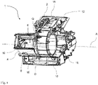
- a ventilation system 1 configured to be installed on a motor vehicle.
- the ventilation system can generate a heating function and/or an air conditioning function, as is the case of the system illustrated in the figure 1 .
- Such a ventilation, heating and/or air conditioning system 1 thermally treats a flow of air sent to the passenger compartment and/or to a component of the vehicle when the driver, a passenger or a function of the vehicle so requests, this flow of air being able to be cooled or heated and thus participate in cooling or heating the passenger compartment and/or the component of the vehicle.
- Such a ventilation, heating and/or air conditioning system 1 is thus configured to send this flow of air to a compartment of the vehicle other than the passenger compartment, such as for example a battery pack of propulsion of the vehicle or an engine compartment of the vehicle, without departing from the scope of the invention.
- the invention finds application when the ventilation, heating and/or air conditioning system 1 is subjected to liquid splashes originating from an environment external to this system.
- the ventilation, heating and/or air conditioning system 1 comprises a first casing 2 and a second casing 4 cooperating with the first casing 2 to delimit an internal volume 6 configured to house at least one ventilation member.
- an internal volume 6 configured to house at least one ventilation member.
- other components such as at least one heat exchanger, one filter, distribution or mixing flaps can be arranged in the internal volume 6, without departing from the scope of the invention.
- the first casing 2 and the second casing 4 are secured to one another by fastening means 8, such as screws for example.
- the internal volume forms a circuit for guiding a flow of air circulated by the ventilation member through the ventilation, heating and/or air conditioning system 1, the boxes 2, 4 being constitutive of the guide circuit.
- any one of the first or second casing 2, 4 can carry a ventilation motor of the ventilation member constituting the ventilation, heating and/or air conditioning system 1.
- the internal volume 6 is thus configured to be able to at least accommodate on the one hand a propeller of the ventilation member and on the other hand the ventilation motor of said member.
- the ventilation, heating and/or ventilation system 1 also comprises a guide structure 12 defining an airflow circulation path and comprising at least one air inlet 10 arranged at the level of the second casing 4 and a plurality air outlets 16 extending here outside and along the housings 2, 4.
- the internal volume 6 thus communicates aeraulically with the air outlets 16 of the guide structure 12.
- the ventilation, heating and/or air conditioning system 1 is shown according to a first embodiment, where the boxes 2, 4 are of complex shape.
- the boxes 2, 4 extend longitudinally along a first axis A, the air outlet 16 of the guide structure 12 also extending mainly along the first axis A.
- the internal volume 6 delimited by the housings 2, 4 take on a generally cylindrical shape configured to accommodate the ventilation member.
- the first casing 2 comprises an opening 18 forming a generally circular volute through which the ventilation member passes to be installed in the internal volume 6.
- the ventilation system 1 is shown according to a second embodiment, where the first casing 2 and the second casing 4 form an assembly of generally cylindrical shape whose main dimension of extension is measured along an axis perpendicular to an axis of rotation B of the propeller of the ventilation unit.
- the dimension of the boxes 2, 4 measured along the first axis A is less important than the diameter of the cylinder.
- the ventilation system 1 comprises a support 26 of the motor of the ventilation member configured to cooperate with the housing 2, 4 comprising the opening 18, the support 26 covering the opening 18 once installed on said housing 2, 4.
- the support 26 also carries the ventilation member, here reference 24, that is to say that the support 26 is integral with the ventilation member 24.
- the support 26 is here made integral with the housing 2, 4 carrying the opening 18 by reversible fastening means 8 such as screws.
- the ventilation system 1 comprises at least one sealing device 28 between the first casing 2 and the second casing 4, preventing any passage of fluid between the internal volume 6 defined by the casings 2, 4 and the external environment of the ventilation, heating and/or air conditioning system 1.
- This sealing device 28 can also be implemented at the level of the connection between the support 26 and the casing 2, 4 carrying the opening 18 .
- the first casing 2 comprises a wall 29 having a peripheral edge 30, the second casing 4 comprising a wall 31 having a peripheral side 32 facing the peripheral edge 30 of the first casing 2, when the casings 2, 4 cooperate with one another. 'other.
- the peripheral edge 30 comprises a groove 34 constituting the sealing device 28 of the ventilation, heating and/or air conditioning system 1.
- the second casing 4 comprises a rib 36 projecting from the peripheral side 32 and which is configured to cooperate with the groove 34 so as to seal the connection between the first casing 2 and the second casing 4, this rib 36 also constituting the sealing device 28.
- the peripheral edge 30 of the first casing 2 comprises at least one boss 38 extending towards the inside of the groove 34. More precisely, the peripheral edge 30 comprises an internal face 40 defining the groove 34.
- the face internal 40 of the peripheral edge 30 takes the form of a "V" in the peripheral edge 30 according to a section in a plane in which is inscribed the first axis A or the axis of rotation B and an axis extending radially by relative to the boxes 2, 4.
- the internal face 40 thus comprises two support flanks 42 and a groove bottom 44, the support flanks 42 extending from the groove bottom 44 to an inlet mouth 46 of the groove 34.
- the boss 38 of the edge device 30 is arranged on one of the bearing flanks 42 of the groove 34, between the inlet mouth 46 and the groove bottom 44.
- the term "inwards” means that the boss 38 extends from one of the support flanks 42 of the peripheral edge 30 towards the other support flank 42, in the space forming the groove 34.
- the boss 38 is a counter shape which decreases a width of the groove 34 measured between the two bearing flanks 42, as one approaches the bottom of the groove 44.
- the dimension measured between the two support flanks 42 at the groove bottom 44 is less than the dimension measured between the two support flanks 42 at the top of the boss 38, this latter measurement also being less than the dimension measured between the two flanks support 42 at the level of the inlet mouth 46.
- a height is measured along the first axis A or the axis of rotation B
- a width is measured along an axis perpendicular to the first axis A or to the axis of rotation B and extending into the cutting plane Q shown in the figure 1 and 2 .
- the peripheral edge 30 comprises a first boss 38a and a second boss 38b each extending towards the inside of the groove 34 one in the direction of the other.
- the first boss 38a and the second boss 38b have the same shape and are symmetrical with respect to each other with respect to a plane passing through the bottom of the groove 44 and equidistant from each of the bearing flanks 42 at the level of the entrance mouth 46.
- the dimension measured between the two support flanks 42 at the level of the groove bottom 44 is less than the dimension measured between the two support flanks 42 at the level of the top of the first and second bosses 38a, 38b, this latter measurement also being less than the dimension measured between the two support flanks 42 at the level of the inlet mouth 46 of the groove 34.
- the rib 36 of the second casing 4 is configured to be housed in the groove 34 of the first casing 2 and ensure sealing between the external environment of the ventilation, heating and/or air conditioning system and the internal volume of this system .
- the rib 36 is at least partially made of an elastically deformable material.
- “Elastically deformable” means a material configured to return to an initial position after having undergone mechanical deformation.
- the elastically deformable material covering the rib 36 is for example a synthetic rubber, of the ethylene-propylene-diene monomer (EPDM) type or of the acrylic nitrile butadiene (NBR) type, this list not being exhaustive.
- the rib 36 comprises at least one nipple 48 made of the same material as that of the second casing 4, the material of the second casing 4 having a Young's modulus greater than that of the elastically deformable material.
- Young's modulus it is understood that the teat 48 has a deformation threshold, which corresponds to a force value from which the material is likely to deform, this deformation threshold of the material constituting the teat 48 being more greater than that of the elastically deformable material of the rib 36. In other words, a greater force will be required to deform the teat 48 compared to the force necessary to deform the elastically deformable material, all other things being equal.
- the second casing 4, and advantageously the first casing 2 is mainly composed of polyamide (PA66) which can be reinforced with 30 to 60% glass fibers (GF30 or GF60). This type of material is by definition more rigid than the elastically deformable material constituting at least partially the rib 36.
- the rib 36 is entirely composed of an elastically deformable material. It is understood that the rib 36 does not include a teat 48 and that it is made of a different material from that of which the second casing 4 and/or the first casing 2 are mainly composed.
- the rib 36 comprises a cap 50 made of elastically deformable material and completely covering the teat 48. More particularly, the cap 50 is configured to be in contact with the groove 34 so as to provide a seal at the connection between the rib 36 and the groove 34.
- This cap 50 takes the form of a "V" stretching from a base 52 arranged at the level of the teat 48 to a free end 54 forming a point and configured to face the bottom groove 44, or even to be in contact with the groove bottom 44.
- the cap 50 comprises an internal contact face 56 and an external contact face 58 extending between the end 54 and the base 52 of the cap 50, the internal contact face 56 being oriented towards the internal volume delimited by the first and second housings, the external contact face 58 being oriented towards the external environment of the housings.
- the rib 36 has a first width L1 measured along a reference line C which is a radial direction of the casing 2, 4 extending in the section plane Q and being perpendicular to the first axis A or to the axis of rotation B.
- the first casing 2 and the second casing 4 are brought together, this movement taking place along the first axis A.
- the free end 54 of cap 50 of the rib 36 approaches the bottom of the groove 44, the contact faces 56, 58 of the cap 50 sliding along the bearing flanks 42 of the groove 34.
- at least one boss 38, and advantageously two bosses 38 exert pressure on one of the contact faces 56, 58 of the cap 50, and advantageously on each of the contact faces 56 , 58 from cap 50.
- the bead 60 of the cap 50 has accumulated in the area of the groove 34 located between the top(s) of the boss(es) 38 and the inlet mouth 46 of the groove 34 remains in this zone, while the end 54 of the cap 50 faces the bottom of the groove 44, thus increasing the level of tightness of the sealing device 28.
- the rib 36 has a second width L2 reduced with respect to the first width L1, by pressing at least one of the bosses 38 of the groove 34, this width being measured in the section plane Q represented on the figure 1 and 2 .
- a dimension of the rib 36 measured at a chosen height at the level of the part located between the end 54 of the cap 50 and the bead 60 is reduced by pressing the boss or bosses 38 compared to a dimension measured at the same height when the rib 36 does not cooperate with the groove 34, that is to say before the installation of the second casing 4 on the first casing 2.
- the force(s) F exerted by the boss(es) 38 on the contact faces 56, 58 of the cap 50 refine the cap 50 at the level of the zone located between the end 54 of the cap 50 and the bead 60, while widening the bead 60.
- a height is measured along the first axis A or the axis of rotation B
- a width is measured along an axis perpendicular to the first axis A or to the axis of rotation B and extending in the cutting plane Q illustrated in the figure 1 and 2 .
- the internal face 40 of the groove 34 is covered with an elastically deformable material at the level of at least one boss 38.
- the first boss 38a and the second boss 38b are formed by a layer 51 of elastically deformable material.
- the rib 36 for its part is advantageously made of the same material as that of the second casing and/or of the first casing. It is understood that at least one boss 38 is formed by a layer 51 of elastically deformable material. In this embodiment, it is the layer 51 which is deformed during the cooperation between the rib 36 and the groove 36, whereas in the first embodiment it is the cap. It is thus the deformation of the layer 51 which increases the contact surface between the rib 36 and the groove 36 and optimizes the seal between the two housings 2, 4.
- the rib 36 sinks into the groove 34, and it is the boss 38 which deforms during this insertion. Indeed, part of the material of the boss 38 accumulates in the bottom of the groove 44 by the movement of the rib 36. Once the boxes are in place, the contact faces 56, 58 of the rib 36 will be in contact of each of the bearing flanks 42 of the groove 34 and of the deformed boss(es) 38 and thus provide sealing at this junction.
Landscapes
- Engineering & Computer Science (AREA)
- Mechanical Engineering (AREA)
- General Engineering & Computer Science (AREA)
- Physics & Mathematics (AREA)
- Thermal Sciences (AREA)
- Geometry (AREA)
- Air-Conditioning For Vehicles (AREA)
Priority Applications (2)
| Application Number | Priority Date | Filing Date | Title |
|---|---|---|---|
| EP20211130.8A EP4008573B1 (de) | 2020-12-01 | 2020-12-01 | Lüftungs-, heizungs- und/oder klimaanlage eines kraftfahrzeugs |
| PCT/EP2021/082910 WO2022117420A1 (fr) | 2020-12-01 | 2021-11-25 | Système de ventilation, de chauffage et/ou d'air conditionné d'un véhicule automobile |
Applications Claiming Priority (1)
| Application Number | Priority Date | Filing Date | Title |
|---|---|---|---|
| EP20211130.8A EP4008573B1 (de) | 2020-12-01 | 2020-12-01 | Lüftungs-, heizungs- und/oder klimaanlage eines kraftfahrzeugs |
Publications (2)
| Publication Number | Publication Date |
|---|---|
| EP4008573A1 true EP4008573A1 (de) | 2022-06-08 |
| EP4008573B1 EP4008573B1 (de) | 2023-10-11 |
Family
ID=73694775
Family Applications (1)
| Application Number | Title | Priority Date | Filing Date |
|---|---|---|---|
| EP20211130.8A Active EP4008573B1 (de) | 2020-12-01 | 2020-12-01 | Lüftungs-, heizungs- und/oder klimaanlage eines kraftfahrzeugs |
Country Status (2)
| Country | Link |
|---|---|
| EP (1) | EP4008573B1 (de) |
| WO (1) | WO2022117420A1 (de) |
Citations (5)
| Publication number | Priority date | Publication date | Assignee | Title |
|---|---|---|---|---|
| US5954578A (en) * | 1996-08-05 | 1999-09-21 | Denso Corporation | Air conditioner for a vehicle |
| US20050047853A1 (en) * | 2003-08-26 | 2005-03-03 | Pettitt Edward Douglas | Integrally molded lateral compression seal |
| US20110017742A1 (en) * | 2009-07-23 | 2011-01-27 | Delphi Technologies, Inc. | In-Groove Snap Fastener |
| EP2607118A1 (de) * | 2011-12-19 | 2013-06-26 | Behr GmbH & Co. KG | Gehäuse insbesondere für eine Kraftfahrzeugklimaanlage |
| DE202017102919U1 (de) * | 2017-05-15 | 2017-06-20 | Mahle International Gmbh | Ringförmige Dichtung |
-
2020
- 2020-12-01 EP EP20211130.8A patent/EP4008573B1/de active Active
-
2021
- 2021-11-25 WO PCT/EP2021/082910 patent/WO2022117420A1/fr not_active Ceased
Patent Citations (5)
| Publication number | Priority date | Publication date | Assignee | Title |
|---|---|---|---|---|
| US5954578A (en) * | 1996-08-05 | 1999-09-21 | Denso Corporation | Air conditioner for a vehicle |
| US20050047853A1 (en) * | 2003-08-26 | 2005-03-03 | Pettitt Edward Douglas | Integrally molded lateral compression seal |
| US20110017742A1 (en) * | 2009-07-23 | 2011-01-27 | Delphi Technologies, Inc. | In-Groove Snap Fastener |
| EP2607118A1 (de) * | 2011-12-19 | 2013-06-26 | Behr GmbH & Co. KG | Gehäuse insbesondere für eine Kraftfahrzeugklimaanlage |
| DE202017102919U1 (de) * | 2017-05-15 | 2017-06-20 | Mahle International Gmbh | Ringförmige Dichtung |
Also Published As
| Publication number | Publication date |
|---|---|
| EP4008573B1 (de) | 2023-10-11 |
| WO2022117420A1 (fr) | 2022-06-09 |
Similar Documents
| Publication | Publication Date | Title |
|---|---|---|
| FR2662758A1 (fr) | Dispositif de transmission de couple. | |
| FR2812383A1 (fr) | Dispositif pour l'assemblage d'au moins un equipement sur un echangeur de chaleur | |
| FR2588354A1 (fr) | Dispositif de raccordement d'un tuyau elastiquement deformable a un tube rigide | |
| FR2737062A1 (fr) | Dispositif pour supporter un moteur electrique entrainant une turbine, notamment pour appareil de chauffage et/ou climatisation de vehicule automobile | |
| WO2014006305A1 (fr) | Climatiseur, notamment pour véhicule automobile | |
| FR2789140A1 (fr) | Dispositif de debrayage a commande hydraulique | |
| EP4008573B1 (de) | Lüftungs-, heizungs- und/oder klimaanlage eines kraftfahrzeugs | |
| EP0213977B1 (de) | Dichtung für die Lenkvorrichtung eines Fahrzeuges | |
| FR2564547A1 (fr) | Mecanisme d'embrayage a retenue axiale d'un plateau de pression. | |
| WO2012028801A1 (fr) | Boîte de degazage destinee au circuit de refroidissement d'un moteur thermique de vehicule automobile | |
| FR2777968A1 (fr) | Dispositifde fixation d'un tube sur un support,en particulier dans un vehicule automobilie | |
| FR2933876A1 (fr) | Element de filtre et systeme de filtre, notamment pour un moteur a combustion interne | |
| FR2564546A1 (fr) | Mecanisme d'embrayage a sens de rotation privilegie. | |
| FR3022987B1 (fr) | Dispositif de generation d'un flux d'air | |
| WO2021151921A1 (fr) | Dispositif thermostatique pour réguler la circulation d'un fluide, ainsi que vanne thermostatique comprenant un tel dispositif | |
| FR2834672A1 (fr) | Module d'etancheite destine notamment a un bloc detendeur de climatisation de vehicule automobile | |
| FR2745038A1 (fr) | Dispositif de positionnement pour filtre a air de moteur a combustion interne | |
| FR2954739A1 (fr) | Dispositif de type essuie-glace comportant un moteur et des moyens de fixation dudit moteur sur une paroi de vehicule automobile. | |
| EP1211425A1 (de) | Dichtungseinheit für eine Kühlmittelpumpe | |
| FR2698669A1 (fr) | Dispositif de retenue d'une vis sur une pièce moulée. | |
| FR2774423A1 (fr) | Boitier de derivation pour la circulation d'un fluide caloporteur dans un moteur a combustion interne | |
| FR2877419A1 (fr) | Bague d'adaptation et support pour groupe moto-ventilateur d'appareils de climatisation. | |
| EP4479638A1 (de) | Verfahren zur herstellung einer schaltung für ein kraftfahrzeug | |
| FR2784598A1 (fr) | Filtre a liquide pour moteur a combustion interne | |
| FR3139295A1 (fr) | Module thermique pour véhicule automobile. |
Legal Events
| Date | Code | Title | Description |
|---|---|---|---|
| PUAI | Public reference made under article 153(3) epc to a published international application that has entered the european phase |
Free format text: ORIGINAL CODE: 0009012 |
|
| STAA | Information on the status of an ep patent application or granted ep patent |
Free format text: STATUS: THE APPLICATION HAS BEEN PUBLISHED |
|
| AK | Designated contracting states |
Kind code of ref document: A1 Designated state(s): AL AT BE BG CH CY CZ DE DK EE ES FI FR GB GR HR HU IE IS IT LI LT LU LV MC MK MT NL NO PL PT RO RS SE SI SK SM TR |
|
| STAA | Information on the status of an ep patent application or granted ep patent |
Free format text: STATUS: REQUEST FOR EXAMINATION WAS MADE |
|
| 17P | Request for examination filed |
Effective date: 20221208 |
|
| RBV | Designated contracting states (corrected) |
Designated state(s): AL AT BE BG CH CY CZ DE DK EE ES FI FR GB GR HR HU IE IS IT LI LT LU LV MC MK MT NL NO PL PT RO RS SE SI SK SM TR |
|
| GRAP | Despatch of communication of intention to grant a patent |
Free format text: ORIGINAL CODE: EPIDOSNIGR1 |
|
| STAA | Information on the status of an ep patent application or granted ep patent |
Free format text: STATUS: GRANT OF PATENT IS INTENDED |
|
| RIC1 | Information provided on ipc code assigned before grant |
Ipc: F04D 29/08 20060101ALI20230414BHEP Ipc: F16J 15/10 20060101ALI20230414BHEP Ipc: F16J 15/06 20060101ALI20230414BHEP Ipc: F16B 5/00 20060101ALI20230414BHEP Ipc: F04D 29/42 20060101ALI20230414BHEP Ipc: B60H 1/00 20060101AFI20230414BHEP |
|
| INTG | Intention to grant announced |
Effective date: 20230515 |
|
| P01 | Opt-out of the competence of the unified patent court (upc) registered |
Effective date: 20230603 |
|
| GRAS | Grant fee paid |
Free format text: ORIGINAL CODE: EPIDOSNIGR3 |
|
| GRAA | (expected) grant |
Free format text: ORIGINAL CODE: 0009210 |
|
| STAA | Information on the status of an ep patent application or granted ep patent |
Free format text: STATUS: THE PATENT HAS BEEN GRANTED |
|
| AK | Designated contracting states |
Kind code of ref document: B1 Designated state(s): AL AT BE BG CH CY CZ DE DK EE ES FI FR GB GR HR HU IE IS IT LI LT LU LV MC MK MT NL NO PL PT RO RS SE SI SK SM TR |
|
| REG | Reference to a national code |
Ref country code: GB Ref legal event code: FG4D Free format text: NOT ENGLISH |
|
| REG | Reference to a national code |
Ref country code: CH Ref legal event code: EP |
|
| REG | Reference to a national code |
Ref country code: DE Ref legal event code: R096 Ref document number: 602020018987 Country of ref document: DE |
|
| REG | Reference to a national code |
Ref country code: IE Ref legal event code: FG4D Free format text: LANGUAGE OF EP DOCUMENT: FRENCH |
|
| REG | Reference to a national code |
Ref country code: LT Ref legal event code: MG9D |
|
| REG | Reference to a national code |
Ref country code: NL Ref legal event code: MP Effective date: 20231011 |
|
| REG | Reference to a national code |
Ref country code: AT Ref legal event code: MK05 Ref document number: 1619874 Country of ref document: AT Kind code of ref document: T Effective date: 20231011 |
|
| PG25 | Lapsed in a contracting state [announced via postgrant information from national office to epo] |
Ref country code: NL Free format text: LAPSE BECAUSE OF FAILURE TO SUBMIT A TRANSLATION OF THE DESCRIPTION OR TO PAY THE FEE WITHIN THE PRESCRIBED TIME-LIMIT Effective date: 20231011 |
|
| PG25 | Lapsed in a contracting state [announced via postgrant information from national office to epo] |
Ref country code: GR Free format text: LAPSE BECAUSE OF FAILURE TO SUBMIT A TRANSLATION OF THE DESCRIPTION OR TO PAY THE FEE WITHIN THE PRESCRIBED TIME-LIMIT Effective date: 20240112 |
|
| PG25 | Lapsed in a contracting state [announced via postgrant information from national office to epo] |
Ref country code: IS Free format text: LAPSE BECAUSE OF FAILURE TO SUBMIT A TRANSLATION OF THE DESCRIPTION OR TO PAY THE FEE WITHIN THE PRESCRIBED TIME-LIMIT Effective date: 20240211 |
|
| PG25 | Lapsed in a contracting state [announced via postgrant information from national office to epo] |
Ref country code: LT Free format text: LAPSE BECAUSE OF FAILURE TO SUBMIT A TRANSLATION OF THE DESCRIPTION OR TO PAY THE FEE WITHIN THE PRESCRIBED TIME-LIMIT Effective date: 20231011 |
|
| PG25 | Lapsed in a contracting state [announced via postgrant information from national office to epo] |
Ref country code: AT Free format text: LAPSE BECAUSE OF FAILURE TO SUBMIT A TRANSLATION OF THE DESCRIPTION OR TO PAY THE FEE WITHIN THE PRESCRIBED TIME-LIMIT Effective date: 20231011 |
|
| PG25 | Lapsed in a contracting state [announced via postgrant information from national office to epo] |
Ref country code: ES Free format text: LAPSE BECAUSE OF FAILURE TO SUBMIT A TRANSLATION OF THE DESCRIPTION OR TO PAY THE FEE WITHIN THE PRESCRIBED TIME-LIMIT Effective date: 20231011 |
|
| PG25 | Lapsed in a contracting state [announced via postgrant information from national office to epo] |
Ref country code: LT Free format text: LAPSE BECAUSE OF FAILURE TO SUBMIT A TRANSLATION OF THE DESCRIPTION OR TO PAY THE FEE WITHIN THE PRESCRIBED TIME-LIMIT Effective date: 20231011 Ref country code: IS Free format text: LAPSE BECAUSE OF FAILURE TO SUBMIT A TRANSLATION OF THE DESCRIPTION OR TO PAY THE FEE WITHIN THE PRESCRIBED TIME-LIMIT Effective date: 20240211 Ref country code: GR Free format text: LAPSE BECAUSE OF FAILURE TO SUBMIT A TRANSLATION OF THE DESCRIPTION OR TO PAY THE FEE WITHIN THE PRESCRIBED TIME-LIMIT Effective date: 20240112 Ref country code: ES Free format text: LAPSE BECAUSE OF FAILURE TO SUBMIT A TRANSLATION OF THE DESCRIPTION OR TO PAY THE FEE WITHIN THE PRESCRIBED TIME-LIMIT Effective date: 20231011 Ref country code: BG Free format text: LAPSE BECAUSE OF FAILURE TO SUBMIT A TRANSLATION OF THE DESCRIPTION OR TO PAY THE FEE WITHIN THE PRESCRIBED TIME-LIMIT Effective date: 20240111 Ref country code: AT Free format text: LAPSE BECAUSE OF FAILURE TO SUBMIT A TRANSLATION OF THE DESCRIPTION OR TO PAY THE FEE WITHIN THE PRESCRIBED TIME-LIMIT Effective date: 20231011 Ref country code: PT Free format text: LAPSE BECAUSE OF FAILURE TO SUBMIT A TRANSLATION OF THE DESCRIPTION OR TO PAY THE FEE WITHIN THE PRESCRIBED TIME-LIMIT Effective date: 20240212 |
|
| PG25 | Lapsed in a contracting state [announced via postgrant information from national office to epo] |
Ref country code: SE Free format text: LAPSE BECAUSE OF FAILURE TO SUBMIT A TRANSLATION OF THE DESCRIPTION OR TO PAY THE FEE WITHIN THE PRESCRIBED TIME-LIMIT Effective date: 20231011 Ref country code: RS Free format text: LAPSE BECAUSE OF FAILURE TO SUBMIT A TRANSLATION OF THE DESCRIPTION OR TO PAY THE FEE WITHIN THE PRESCRIBED TIME-LIMIT Effective date: 20231011 Ref country code: PL Free format text: LAPSE BECAUSE OF FAILURE TO SUBMIT A TRANSLATION OF THE DESCRIPTION OR TO PAY THE FEE WITHIN THE PRESCRIBED TIME-LIMIT Effective date: 20231011 Ref country code: NO Free format text: LAPSE BECAUSE OF FAILURE TO SUBMIT A TRANSLATION OF THE DESCRIPTION OR TO PAY THE FEE WITHIN THE PRESCRIBED TIME-LIMIT Effective date: 20240111 Ref country code: LV Free format text: LAPSE BECAUSE OF FAILURE TO SUBMIT A TRANSLATION OF THE DESCRIPTION OR TO PAY THE FEE WITHIN THE PRESCRIBED TIME-LIMIT Effective date: 20231011 Ref country code: HR Free format text: LAPSE BECAUSE OF FAILURE TO SUBMIT A TRANSLATION OF THE DESCRIPTION OR TO PAY THE FEE WITHIN THE PRESCRIBED TIME-LIMIT Effective date: 20231011 |
|
| PG25 | Lapsed in a contracting state [announced via postgrant information from national office to epo] |
Ref country code: DK Free format text: LAPSE BECAUSE OF FAILURE TO SUBMIT A TRANSLATION OF THE DESCRIPTION OR TO PAY THE FEE WITHIN THE PRESCRIBED TIME-LIMIT Effective date: 20231011 |
|
| REG | Reference to a national code |
Ref country code: DE Ref legal event code: R097 Ref document number: 602020018987 Country of ref document: DE |
|
| PG25 | Lapsed in a contracting state [announced via postgrant information from national office to epo] |
Ref country code: CZ Free format text: LAPSE BECAUSE OF FAILURE TO SUBMIT A TRANSLATION OF THE DESCRIPTION OR TO PAY THE FEE WITHIN THE PRESCRIBED TIME-LIMIT Effective date: 20231011 |
|
| PG25 | Lapsed in a contracting state [announced via postgrant information from national office to epo] |
Ref country code: SK Free format text: LAPSE BECAUSE OF FAILURE TO SUBMIT A TRANSLATION OF THE DESCRIPTION OR TO PAY THE FEE WITHIN THE PRESCRIBED TIME-LIMIT Effective date: 20231011 |
|
| PG25 | Lapsed in a contracting state [announced via postgrant information from national office to epo] |
Ref country code: SM Free format text: LAPSE BECAUSE OF FAILURE TO SUBMIT A TRANSLATION OF THE DESCRIPTION OR TO PAY THE FEE WITHIN THE PRESCRIBED TIME-LIMIT Effective date: 20231011 Ref country code: SK Free format text: LAPSE BECAUSE OF FAILURE TO SUBMIT A TRANSLATION OF THE DESCRIPTION OR TO PAY THE FEE WITHIN THE PRESCRIBED TIME-LIMIT Effective date: 20231011 Ref country code: RO Free format text: LAPSE BECAUSE OF FAILURE TO SUBMIT A TRANSLATION OF THE DESCRIPTION OR TO PAY THE FEE WITHIN THE PRESCRIBED TIME-LIMIT Effective date: 20231011 Ref country code: IT Free format text: LAPSE BECAUSE OF FAILURE TO SUBMIT A TRANSLATION OF THE DESCRIPTION OR TO PAY THE FEE WITHIN THE PRESCRIBED TIME-LIMIT Effective date: 20231011 Ref country code: EE Free format text: LAPSE BECAUSE OF FAILURE TO SUBMIT A TRANSLATION OF THE DESCRIPTION OR TO PAY THE FEE WITHIN THE PRESCRIBED TIME-LIMIT Effective date: 20231011 Ref country code: DK Free format text: LAPSE BECAUSE OF FAILURE TO SUBMIT A TRANSLATION OF THE DESCRIPTION OR TO PAY THE FEE WITHIN THE PRESCRIBED TIME-LIMIT Effective date: 20231011 Ref country code: CZ Free format text: LAPSE BECAUSE OF FAILURE TO SUBMIT A TRANSLATION OF THE DESCRIPTION OR TO PAY THE FEE WITHIN THE PRESCRIBED TIME-LIMIT Effective date: 20231011 |
|
| REG | Reference to a national code |
Ref country code: CH Ref legal event code: PL |
|
| PLBE | No opposition filed within time limit |
Free format text: ORIGINAL CODE: 0009261 |
|
| STAA | Information on the status of an ep patent application or granted ep patent |
Free format text: STATUS: NO OPPOSITION FILED WITHIN TIME LIMIT |
|
| PG25 | Lapsed in a contracting state [announced via postgrant information from national office to epo] |
Ref country code: LU Free format text: LAPSE BECAUSE OF NON-PAYMENT OF DUE FEES Effective date: 20231201 |
|
| PG25 | Lapsed in a contracting state [announced via postgrant information from national office to epo] |
Ref country code: MC Free format text: LAPSE BECAUSE OF FAILURE TO SUBMIT A TRANSLATION OF THE DESCRIPTION OR TO PAY THE FEE WITHIN THE PRESCRIBED TIME-LIMIT Effective date: 20231011 |
|
| REG | Reference to a national code |
Ref country code: BE Ref legal event code: MM Effective date: 20231231 |
|
| PG25 | Lapsed in a contracting state [announced via postgrant information from national office to epo] |
Ref country code: MC Free format text: LAPSE BECAUSE OF FAILURE TO SUBMIT A TRANSLATION OF THE DESCRIPTION OR TO PAY THE FEE WITHIN THE PRESCRIBED TIME-LIMIT Effective date: 20231011 Ref country code: LU Free format text: LAPSE BECAUSE OF NON-PAYMENT OF DUE FEES Effective date: 20231201 |
|
| 26N | No opposition filed |
Effective date: 20240712 |
|
| REG | Reference to a national code |
Ref country code: IE Ref legal event code: MM4A |
|
| PG25 | Lapsed in a contracting state [announced via postgrant information from national office to epo] |
Ref country code: IE Free format text: LAPSE BECAUSE OF NON-PAYMENT OF DUE FEES Effective date: 20231201 |
|
| PG25 | Lapsed in a contracting state [announced via postgrant information from national office to epo] |
Ref country code: BE Free format text: LAPSE BECAUSE OF NON-PAYMENT OF DUE FEES Effective date: 20231231 |
|
| PG25 | Lapsed in a contracting state [announced via postgrant information from national office to epo] |
Ref country code: CH Free format text: LAPSE BECAUSE OF NON-PAYMENT OF DUE FEES Effective date: 20231231 |
|
| PG25 | Lapsed in a contracting state [announced via postgrant information from national office to epo] |
Ref country code: SI Free format text: LAPSE BECAUSE OF FAILURE TO SUBMIT A TRANSLATION OF THE DESCRIPTION OR TO PAY THE FEE WITHIN THE PRESCRIBED TIME-LIMIT Effective date: 20231011 |
|
| PG25 | Lapsed in a contracting state [announced via postgrant information from national office to epo] |
Ref country code: SI Free format text: LAPSE BECAUSE OF FAILURE TO SUBMIT A TRANSLATION OF THE DESCRIPTION OR TO PAY THE FEE WITHIN THE PRESCRIBED TIME-LIMIT Effective date: 20231011 Ref country code: IE Free format text: LAPSE BECAUSE OF NON-PAYMENT OF DUE FEES Effective date: 20231201 Ref country code: CH Free format text: LAPSE BECAUSE OF NON-PAYMENT OF DUE FEES Effective date: 20231231 Ref country code: BE Free format text: LAPSE BECAUSE OF NON-PAYMENT OF DUE FEES Effective date: 20231231 |
|
| PG25 | Lapsed in a contracting state [announced via postgrant information from national office to epo] |
Ref country code: FI Free format text: LAPSE BECAUSE OF FAILURE TO SUBMIT A TRANSLATION OF THE DESCRIPTION OR TO PAY THE FEE WITHIN THE PRESCRIBED TIME-LIMIT Effective date: 20231011 |
|
| PG25 | Lapsed in a contracting state [announced via postgrant information from national office to epo] |
Ref country code: CY Free format text: LAPSE BECAUSE OF FAILURE TO SUBMIT A TRANSLATION OF THE DESCRIPTION OR TO PAY THE FEE WITHIN THE PRESCRIBED TIME-LIMIT; INVALID AB INITIO Effective date: 20201201 |
|
| PG25 | Lapsed in a contracting state [announced via postgrant information from national office to epo] |
Ref country code: HU Free format text: LAPSE BECAUSE OF FAILURE TO SUBMIT A TRANSLATION OF THE DESCRIPTION OR TO PAY THE FEE WITHIN THE PRESCRIBED TIME-LIMIT; INVALID AB INITIO Effective date: 20201201 |
|
| GBPC | Gb: european patent ceased through non-payment of renewal fee |
Effective date: 20241201 |
|
| PG25 | Lapsed in a contracting state [announced via postgrant information from national office to epo] |
Ref country code: GB Free format text: LAPSE BECAUSE OF NON-PAYMENT OF DUE FEES Effective date: 20241201 |
|
| PG25 | Lapsed in a contracting state [announced via postgrant information from national office to epo] |
Ref country code: TR Free format text: LAPSE BECAUSE OF FAILURE TO SUBMIT A TRANSLATION OF THE DESCRIPTION OR TO PAY THE FEE WITHIN THE PRESCRIBED TIME-LIMIT Effective date: 20231011 |
|
| PGFP | Annual fee paid to national office [announced via postgrant information from national office to epo] |
Ref country code: FR Payment date: 20251230 Year of fee payment: 6 |
|
| PGFP | Annual fee paid to national office [announced via postgrant information from national office to epo] |
Ref country code: DE Payment date: 20251231 Year of fee payment: 6 |