EP4008583B1 - Siège auto pour enfant - Google Patents
Siège auto pour enfant Download PDFInfo
- Publication number
- EP4008583B1 EP4008583B1 EP21210818.7A EP21210818A EP4008583B1 EP 4008583 B1 EP4008583 B1 EP 4008583B1 EP 21210818 A EP21210818 A EP 21210818A EP 4008583 B1 EP4008583 B1 EP 4008583B1
- Authority
- EP
- European Patent Office
- Prior art keywords
- seat
- engagement
- supporting body
- rotatable supporting
- car
- Prior art date
- Legal status (The legal status is an assumption and is not a legal conclusion. Google has not performed a legal analysis and makes no representation as to the accuracy of the status listed.)
- Active
Links
Images





Classifications
-
- B—PERFORMING OPERATIONS; TRANSPORTING
- B60—VEHICLES IN GENERAL
- B60N—SEATS SPECIALLY ADAPTED FOR VEHICLES; VEHICLE PASSENGER ACCOMMODATION NOT OTHERWISE PROVIDED FOR
- B60N2/00—Seats specially adapted for vehicles; Arrangement or mounting of seats in vehicles
- B60N2/24—Seats specially adapted for vehicles; Arrangement or mounting of seats in vehicles for particular purposes or particular vehicles
- B60N2/26—Seats specially adapted for vehicles; Arrangement or mounting of seats in vehicles for particular purposes or particular vehicles for children
- B60N2/28—Seats readily mountable on, and dismountable from, existing seats or other parts of the vehicle
- B60N2/2821—Seats readily mountable on, and dismountable from, existing seats or other parts of the vehicle having a seat and a base part
- B60N2/2824—Seats readily mountable on, and dismountable from, existing seats or other parts of the vehicle having a seat and a base part part of the base being supported by the vehicle frame
-
- B—PERFORMING OPERATIONS; TRANSPORTING
- B60—VEHICLES IN GENERAL
- B60N—SEATS SPECIALLY ADAPTED FOR VEHICLES; VEHICLE PASSENGER ACCOMMODATION NOT OTHERWISE PROVIDED FOR
- B60N2/00—Seats specially adapted for vehicles; Arrangement or mounting of seats in vehicles
- B60N2/24—Seats specially adapted for vehicles; Arrangement or mounting of seats in vehicles for particular purposes or particular vehicles
- B60N2/26—Seats specially adapted for vehicles; Arrangement or mounting of seats in vehicles for particular purposes or particular vehicles for children
- B60N2/28—Seats readily mountable on, and dismountable from, existing seats or other parts of the vehicle
- B60N2/2842—Seats readily mountable on, and dismountable from, existing seats or other parts of the vehicle adapted to carry the child, when dismounted from the vehicle
- B60N2/2845—Seats readily mountable on, and dismountable from, existing seats or other parts of the vehicle adapted to carry the child, when dismounted from the vehicle having handles
-
- B—PERFORMING OPERATIONS; TRANSPORTING
- B60—VEHICLES IN GENERAL
- B60N—SEATS SPECIALLY ADAPTED FOR VEHICLES; VEHICLE PASSENGER ACCOMMODATION NOT OTHERWISE PROVIDED FOR
- B60N2/00—Seats specially adapted for vehicles; Arrangement or mounting of seats in vehicles
- B60N2/24—Seats specially adapted for vehicles; Arrangement or mounting of seats in vehicles for particular purposes or particular vehicles
- B60N2/26—Seats specially adapted for vehicles; Arrangement or mounting of seats in vehicles for particular purposes or particular vehicles for children
- B60N2/28—Seats readily mountable on, and dismountable from, existing seats or other parts of the vehicle
- B60N2/2869—Seats readily mountable on, and dismountable from, existing seats or other parts of the vehicle rotatable about a vertical axis
-
- B—PERFORMING OPERATIONS; TRANSPORTING
- B60—VEHICLES IN GENERAL
- B60N—SEATS SPECIALLY ADAPTED FOR VEHICLES; VEHICLE PASSENGER ACCOMMODATION NOT OTHERWISE PROVIDED FOR
- B60N2/00—Seats specially adapted for vehicles; Arrangement or mounting of seats in vehicles
- B60N2/24—Seats specially adapted for vehicles; Arrangement or mounting of seats in vehicles for particular purposes or particular vehicles
- B60N2/26—Seats specially adapted for vehicles; Arrangement or mounting of seats in vehicles for particular purposes or particular vehicles for children
- B60N2/28—Seats readily mountable on, and dismountable from, existing seats or other parts of the vehicle
- B60N2/2887—Fixation to a transversal anchorage bar, e.g. isofix
-
- B—PERFORMING OPERATIONS; TRANSPORTING
- B60—VEHICLES IN GENERAL
- B60N—SEATS SPECIALLY ADAPTED FOR VEHICLES; VEHICLE PASSENGER ACCOMMODATION NOT OTHERWISE PROVIDED FOR
- B60N2/00—Seats specially adapted for vehicles; Arrangement or mounting of seats in vehicles
- B60N2/90—Details or parts not otherwise provided for
- B60N2/919—Positioning and locking mechanisms
- B60N2002/952—Positioning and locking mechanisms characterised by details of the locking system
- B60N2002/957—Positioning and locking mechanisms characterised by details of the locking system the locking system prevents an abnormal or wrong mounting situation, i.e. deployment or functioning of a seat part being prevented if the seat or seat part is not properly mounted
Definitions
- the present invention relates to a child car seat, for transporting children.
- Such child seats are usually constituted by a seat structure inside which the child can be accommodated; the seat structure can be anchored, using devices of various kinds, to the seats of the car so as to ensure that, during the trip, the seat (and as a consequence the child) is stably integral with the seat.
- CN 110 497 826 A discloses an example of a known child car seat.
- the car base is fixed directly to the seat with fixing devices associated with the seats themselves (such as, for example, the automatic coupling means known commercially as ISO-FIX) while the seat structure is coupled (or decoupled) directly to/from the car base, so that the child can be carried by hand or transported on a buggy.
- fixing devices associated with the seats themselves such as, for example, the automatic coupling means known commercially as ISO-FIX
- ISO-FIX the automatic coupling means known commercially as ISO-FIX
- One particular type of car base is constituted by what are called rotatable bases, which make it possible to rotate the seat about a substantially vertical axis, in order to allow its transition from a loading/unloading position, in which the child is facing toward the side, and one or more use positions, in which the child is arranged facing the advancement direction of the vehicle or facing the opposite direction, as required by the international regulations in force.
- the aim of the present invention is to provide a child car seat that is capable of improving the known art in one or more of the above mentioned aspects.
- an object of the invention is to make available a child car seat that allows the decoupling of the seat to be executed in an extremely reliable manner.
- Another object of the invention is to provide a child car seat that is highly reliable, low weight, easy to implement, and of low cost.
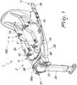
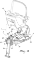
- the child car seat according to the invention particularly for transporting children, generally designated by the reference numeral 1, comprises a car base 2 which can be associated detachably, via fixing means 3, with a seat of a car.
- the fixing means 3 comprise fixing tabs 3a which are provided with automatic coupling terminals, for example of the type commercially known as ISO-FIX.
- the child car seat 1 further comprises a seat element 10, which can be associated detachably with the car base 2 via engagement/disengagement means 4 which are known per se.
- the engagement/disengagement means 4 comprise at least one hook 14 which is supported by the car base 2 and is configured to engage with a respective engagement element 15 supported by the seat element 10.
- the engagement/disengagement means 4 comprise a pair of hooks 14 which are supported by the car base 2 and are configured to engage with a respective engagement element 15 supported by the seat element 10.
- the engagement/disengagement means 4 comprise first and second front and rear hooks 14 which are arranged on at least one longitudinal member 5.
- the engagement/disengagement means 4 are arranged on two longitudinal members 5, which are mutually parallel and are transversely spaced apart.
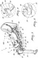
- the car base 2 comprises a fixed framework 2a which supports, so that it can rotate about an axis 100 that is vertical during use, a rotatable supporting body 2b for the engagement/disengagement means 4.
- the rotatable supporting body 2b is adapted to pass from at least one inactive or child loading/unloading position to at least one active or use position.
- the at least one inactive position and the at least one active position are mutually angularly spaced apart about the axis 100.
- the fixed framework 2a supports an actuation device 30a which is connected, by means of a kinematic connection device 30, to the engagement/disengagement means 4 in order to actuate the at least one pair of hooks 14 so as to disengage the respective engagement elements 15.
- the actuation device 30a comprises a first movable handle with oscillatory movement about a tilting axis.
- the seat 1 comprises at least one locking device 50 for the automatic locking of the rotatable supporting body 2b in at least one active or use position.
- the fixed framework 2a supports at least one actuation element 51 which is functionally connected to the locking device 50.
- the actuation element 51 comprises two lateral engagement portions, so that it can be easily moved from both sides of the car base 2.
- the actuation element 51 is connected, through at least one connecting element constituted by a tension member or by a cable, to means for the relative movement of an engagement body 52, which is supported advantageously so that it can slide by the fixed framework 2a, in order to disengage it from a respective seat 53 defined on the rotatable supporting body 2b, so as to allow the mutual rotation of the rotatable supporting body 2b with respect to the fixed framework 2a about the axis 100.
- the actuation element 51 also acts in contrast against elastic contrast means, for example constituted by a spring 55.
- the rotatable supporting body 2b defines two seats 53.
- the two seats 53 comprise a first seat 53a and a second seat 53b which are angularly spaced apart 180° from each other about the axis 100.
- a retention and contrast device 20 is provided for the retention and contrast of the stresses of the rotatable supporting body 2b in the at least one use position.
- the retention and contrast device 20 is configured to contrast any stresses that are generated in the event of an accident.
- a first stress force acts substantially parallel to the direction of travel of the vehicle and a second stress force tends to rip the seat element 10 from the base 2.
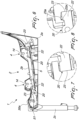
- the retention and contrast device 20 comprises first and second engagement teeth 22 which are supported by the rotatable supporting body 2b and are adapted, when the rotatable supporting body 2b moves into the use position, to engage in a respective engagement seat 23 defined on the fixed framework 2a.
- the engagement teeth 22 extend parallel to the direction of travel of the vehicle and are arranged on opposite sides with respect to the axis 100.
- the engagement teeth 22 are integral with at least one longitudinal member 5 and are oriented away from the axis 100.
- the retention and contrast device 20 comprises a first and a second pair of engagement teeth 22 which are integral with a respective first and second longitudinal member 5 and are oriented away from the axis 100.
- the engagement seats 23 are U-shaped and are supported, mutually opposite and in pairs, directly by the fixed framework 2a, so that, when the rotatable supporting body 2b moves to one of the use conditions, the engagement teeth 22 will be accommodated in a respective engagement seat 23.
- any stresses, directed along the direction of travel of the car and tending to rip the seat element 10 from the car base 2, are transferred directly to the longitudinal members 5, supported by the rotatable supporting body 2b, which are retained directly by the fixed framework 2a by virtue of the coupling between the engagement teeth 22 and the respective engagement seat 23.
- each engagement tooth has an upper edge 22a which is directed upward, and having the respective engagement seat 23 have a lateral retention edge 23a which is directed downward and at least partially faces, on the end directed toward the axis 100, the upper edge 22a.
- the at least one hook 14 can be associated with a first seat element and with a second seat element, different from the first seat element.
- the first seat element comprises an infant seat (also known as a carry cot) and the second seat element comprises a child seat, adapted for children up to a few years old.
- the first seat element is of the type adapted to be used exclusively so that the child is seated facing away from the direction of travel of the car.
- the second seat element is of the type adapted to be used so that the child can be seated facing away from the direction of travel of the car or facing in the direction of travel of the car.
- the engagement/disengagement means 4 are configured to enable the coupling of the second seat element to the rotatable supporting body 2b in both longitudinal orientations.
- the engagement/disengagement means 4 are likewise configured to enable the coupling of the first seat element to the rotatable supporting body 2b in a single longitudinal orientation.
- the rotatable supporting body 2b prefferably has at least one region for interfacing with the seat element 10.
- the region for interfacing is contoured so as not to interfere with the external surface of the second seat element if the latter is coupled to the at least one hook 14 in both longitudinal orientations.
- the interface element is configured so as not to interfere with a respective abutment portion defined on the external surface of the first seat element if the latter is arranged so as to face the rotatable supporting body 2b in order to couple it to the at least one hook 14 in a first longitudinal orientation, while the above mentioned interface element is configured so as to interfere, and consequently prevent the coupling, with the respective abutment portion defined on the external surface of the first seat element if the latter is arranged so as to face the rotatable supporting body 2b in order to couple it to the at least one hook 14 in a second longitudinal orientation, which is opposite the first longitudinal orientation.
- the second seat element can be associated stably with the at least one hook 14 in both longitudinal orientations, in the case of the first seat element, typically an infant seat or a carry cot, by virtue of the interface element it is possible to couple the first seat element only in a longitudinal orientation, and this independently of how the rotatable supporting body 2b is rotated.
- the rotatable supporting body 2b is associated with closure means for the first seat 53a, which are actuated on command following the coupling of the first seat element with the hooks 14.
- an actuation portion defined on the first seat element, engages an abutment body 61 which is defined on the rotatable supporting body 2b and is movable with respect to the above mentioned rotatable supporting body 2b.
- the abutment body 61 moving for example with an oscillating motion about an oscillation axis, actuates the closure means which have a terminal portion 62 which, in such condition, prevents access, from outside, to the first seat 53a by the engagement body 52.
- kinematic connection elements such as, for example, a cable 63 and an interconnecting lever mechanism 64, which is adapted to actuate the displacement of the terminal portion 62.
- the terminal portion is also associated with loading means, comprising for example a spring 65, which are configured to maintain the terminal portion 62 in a condition of disengagement from the first seat 53a.
- loading means comprising for example a spring 65, which are configured to maintain the terminal portion 62 in a condition of disengagement from the first seat 53a.
- the car base 2 is further provided with a display device 90 for showing the correct positioning of the seat element in the active position.
- Such display device is configured to highlight the correct positioning when the engagement body 52 is correctly inserted into the engagement seat 53.
- the display device makes it possible to ascertain the correct positioning only when the first seat element is arranged so that the child is seated, always, facing away from the direction of travel of the car, all in order to prevent errors by the parent/user.
- the kinematic connection device 30 comprises an elongated element 31 which is connected, at one end, to the actuation device 30a and, at the opposite end, to a pusher 32.
- the elongated element 31 comprises a tension member; however, there is no reason not to use different solutions, such as for example a sheathed cable.
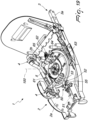
- the pusher 32 has an engagement portion 32a, which can move, as a consequence of the movement of the actuation device 30a, to engage a rotor element 33 which is supported so that it can rotate, about the axis 100, by the fixed framework 2a.
- the rotor element 33 is further connected, by means of a connecting member 34, to an actuation body 35 which is supported so that it can slide by the rotatable supporting body 2b in order to actuate the at least one pair of hooks 14.
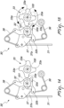
- the rotor element 33 which is integral in rotation with the rotatable supporting body 2b, has a plurality of actuation tabs 33a, which are arranged angularly spaced apart from each other in a manner corresponding to the angular spacing between the various active and inactive positions of the rotatable supporting body 2b, so as to be able to be engaged directly by the pusher 32 independently of the angular position of the rotatable supporting body 2b as clearly shown in the operating arrangement illustrated for the purposes of example in Figures 14 to 17 .
- the actuation tabs 33a are mutually angularly spaced apart by 90° from each other.
- first means of elastic contrast 36 which are configured to contrast the movement of the actuation device 30a.
- the first means of elastic contrast 36 comprise a spring that acts between the pusher 32 and the fixed framework 2a.
- the first means of elastic contrast 36 comprise a first double-arm torsion spring (also known as a trap-pull spring) which is normally splayed or open.
- a first double-arm torsion spring also known as a trap-pull spring
- the pusher 32 is supported so that it can rotate by the fixed framework 2a about an oscillation axis 101 that is substantially parallel to the axis 100.
- a compensation device 37 is interposed between the pusher 32 and the elongated element 31.
- This compensation device 37 is supported by the pusher 32 so that it can rotate, and it has an engagement tab, which can be oscillated following the pressing of the actuation device 30a to command the oscillation of the pusher 37 about its own oscillation axis 101.
- the first means of elastic contrast 36 comprise, for example, a trap-pull spring with splayed arms, which can be connected, at an end of a first arm, to the fixed framework 2a, and at the end of the second arm, to a tab 32b of the pusher 32.
- This pusher tab 32b is kept resting, by the first means of elastic contrast 36, against an abutment portion 37a defined on the pusher 37.
- Elastic means for positioning and for compensating 38 are likewise provided, which act between the pusher 32 and the compensation device 37.
- the presence of the compensation device 37 makes it possible, if the user should rotate the rotatable supporting body base 2b with the actuation device 30a pressed, not to stress the components that make up the kinematic connection device 30.
- the connecting member 34 is configured to convert the rotary movement of the rotor 33 following the actuation of the actuation device 30a to a translation movement of the actuation body 35 which is supported so that it can slide by the rotatable supporting body 2b in order to actuate the release of the at least one pair of hooks 14.
- the connecting member 34 comprises a first elongated body 34a which rotates integrally with the rotor 33 and a link rod 34b which is pivoted at the respective ends to the first elongated body 34a and to the actuation body 35.
- the actuation body 35 is mounted so that it can slide on a track defined by the rotatable supporting body 2b, so that the rotation on command of the rotor element 33 corresponds to a movement of the actuation body 35 along the respective track.
- the engagement/disengagement means 14 comprise a safety device adapted to prevent the accidental disengagement of the at least one hook 4 and a device for moving each hook 4.
- the movement of the actuation element 35 is adapted to determine, in a first segment of movement, the deactivation of the safety device, and in a second segment of movement, the movement of the hook 14.
- the operation of the child car seat 1, according to the invention, is the following.
- the car base 2 is fixed to the seats of the car using the fixing means 3.
- the rotatable supporting body 2b is rotated to the inactive position, so that the seat element 10 is directed to the side, toward the open door of the car, so as to facilitate the loading and unloading of the child.
- the hooks 14 lock onto the engagement elements 15 which are integral with the seat element 10, in order to ensure the fixing of the seat element to the car base.
- the user If the user wishes to bring the rotatable supporting body 2b (and accordingly the seat element 10) into the active or use position, then the user proceeds to rotate the rotatable supporting body 2b about the axis 100, typically by approximately 90°.
- the automatic locking device 20 blocks the rotation about the axis 100.
- the user wishes to uncouple the seat element 10 from the car base 2, he or she proceeds by pressing the actuation device 30a, which is directly supported by the fixed framework 2 and is therefore always easily accessible by the user.
- Pressing the actuation device 30a determines the oscillation, about the oscillation axis 101, of the pusher 32, which, with its engagement portion 32a, makes the rotor element 33 rotate about the axis 100.
- the invention fully achieves the intended aim and objects by providing a child car seat that is extremely reliable both for the locking in the various different angular positions of the rotatable supporting body 2b, and, especially, in the operations to release the hooks 14.
- the particular shape of the rotatable supporting body 2b makes it possible to associate the first seat element (typically a carry cot) in a single longitudinal orientation, allowing it to freely rotate about the axis 100 but allowing it to be locked only in the active position in which the seat element is arranged so that the child is seated facing away from the direction of travel of the car.
- the first seat element typically a carry cot
- any force to which the seat element 10 is subjected during an accident is transferred directly to the longitudinal members 5, supported by the rotatable supporting body 2b, which are retained directly by the fixed framework 2a by virtue of the coupling between the engagement teeth 22 and the respective engagement seat 23.
Landscapes
- Engineering & Computer Science (AREA)
- Health & Medical Sciences (AREA)
- Child & Adolescent Psychology (AREA)
- General Health & Medical Sciences (AREA)
- Aviation & Aerospace Engineering (AREA)
- Transportation (AREA)
- Mechanical Engineering (AREA)
- Seats For Vehicles (AREA)
Claims (10)
- Siège-auto pour enfant (1), en particulier pour transporter des enfants, qui comporte une base de voiture (2) qui peut être associée de manière détachable, via des moyens de fixation (3), à un siège d'une voiture, et un élément de siège (10), qui peut être associé de manière détachable à ladite base de voiture (2) via des moyens de prise/libération (4) supportés par ladite base de voiture (2) qui comportent au moins un crochet (14) configuré pour venir en prise avec un élément de prise (15) respectif supporté par ledit élément de siège (10), ladite base de voiture (2) comportant un châssis fixe (2a) qui supporte, de sorte qu'il peut tourner autour d'un axe (100) qui est vertical pendant l'utilisation, un corps de support rotatif (2b) pour ledit au moins un crochet (14) qui est adapté pour passer d'une position au moins inactive ou de chargement/déchargement d'enfant à au moins deux positions actives ou d'utilisation, ladite au moins une position inactive et lesdites au moins deux positions actives étant mutuellement espacées angulairement autour dudit axe (100), ledit siège-auto pour enfant (1) comportant au moins un dispositif de blocage (50) pour le blocage automatique dudit corps de support rotatif (2b) dans au moins une desdites positions actives ou d'utilisation, ledit châssis fixe (2a) supportant au moins un élément d'actionnement (51), qui est fonctionnellement relié audit dispositif de blocage (50) et est relié à un corps de prise (52) afin de le libérer d'un logement (53) respectif défini sur ledit corps de support rotatif (2b), de manière à permettre la rotation mutuelle dudit corps de support rotatif (2b) par rapport audit châssis fixe (2a) autour dudit axe (100), lesdits deux logements (53) comportant un premier logement (53a) et un second logement (53b) qui sont mutuellement espacés angulairement autour dudit axe (100), ledit au moins un crochet (14) peut être associé à un premier élément de siège et à un second élément de siège, différent du premier élément de siège, ledit premier élément de siège étant du type adapté pour être utilisé exclusivement de sorte que l'enfant s'assoit à l'encontre de la direction de déplacement de la voiture et ledit second élément de siège étant du type adapté pour être utilisé de sorte que l'enfant peut s'asseoir à l'encontre de la direction de déplacement de la voiture ou face à la direction de déplacement de la voiture, caractérisé en ce que lesdits moyens de prise/libération (4) sont configurés pour permettre le couplage dudit second élément de siège audit corps de support rotatif (2b) dans les deux directions longitudinales et dudit premier élément de siège audit corps de support rotatif (2b) dans une seule orientation longitudinale, ledit corps de support rotatif (2b) étant associé à des moyens de fermeture dudit premier logement (53a), lesdits moyens de fermeture étant actionnés sur commande après le couplage dudit premier élément de siège audit au moins un crochet (14).
- Siège-auto pour enfant (1) selon la revendication (1), caractérisé en ce que ledit au moins un crochet (14) est défini sur au moins un élément longitudinal (5) qui est supporté par ladite base de voiture (2) et est configuré pour venir en prise avec un élément de prise (15) respectif supporté par ledit élément de siège (10), un dispositif de retenue et d'opposition (20) pour la retenue et l'opposition aux contraintes du corps de support rotatif (2b) dans la au moins une position d'utilisation étant prévu et étant configuré pour s'opposer à toute contrainte, ledit dispositif de retenue et d'opposition (20) comportant au moins une première dent de prise et au moins une seconde dent de prise (22) qui sont supportées par le corps de support rotatif (2b) et sont adaptées, lorsque ledit corps de support rotatif (2b) se déplace dans la position d'utilisation, pour venir en prise avec un logement de prise (23) respectif défini sur ledit châssis fixe (2a), lesdites au moins deux dents de prise (22) étant solidaires d'au moins un élément longitudinal (5) respectif et étant orientées en s'éloignant de l'axe (100)
- Siège-auto pour enfant (1) selon la revendication 1 ou 2, caractérisé en ce que ledit châssis fixe (2a) supporte un dispositif d'actionnement (30a) qui est relié, au moyen d'un dispositif de liaison cinématique (30), auxdits moyens de prise/libération (4) afin d'actionner ledit au moins un crochet (14) de manière à libérer l'élément de prise (15) respectif, ledit dispositif de liaison cinématique (30) comportant un élément allongé (31) qui est relié, à une extrémité, audit dispositif d'actionnement (30a) et, à l'extrémité opposée, à un poussoir (32) qui a une partie de prise (32a) qui peut se déplacer, en conséquence du mouvement dudit dispositif d'actionnement (30a), pour venir en prise avec un élément de rotor (33) qui est supporté de sorte qu'il peut être mise en rotation, autour dudit axe (100), par ledit châssis fixe (2a),ledit élément de rotor (33) étant relié, au moyen d'un élément de liaison (34), à un corps d'actionnement (35) qui est supporté de sorte qu'il peut glisser par l'intermédiaire dudit corps de support rotatif (2b) afin d'actionner ledit au moins un crochet (14).
- Siège-auto pour enfant (1) selon la revendication 2, caractérisé en ce que lesdits logements de prise (23) sont en forme de U et sont supportés, mutuellement opposés et par paires, directement par ledit châssis fixe (2a).
- Siège-auto pour enfant (1) selon une ou plusieurs des revendications précédentes, caractérisé en ce que ledit élément d'actionnement (51) agit en opposition à des moyens d'opposition élastiques.
- Siège-auto pour enfant (1) selon les revendications 2 ou 4, caractérisé en ce qu'il comporte un appariement de forme entre lesdites dents de prise (22) et le logement de prise (23) respectif.
- Siège-auto pour enfant (1) selon la revendication 6, caractérisé en ce que ledit appariement de forme entraîne que l'extrémité de chaque dent de prise (22) a un bord supérieur (22a) qui est dirigé vers le haut, et que le logement de prise (23) respectif a un bord de retenue latéral (23a) qui est dirigé vers le bas et fait au moins partiellement face, sur l'extrémité dirigée vers l'axe (100), au bord supérieur (22a) respectif .
- Siège-auto pour enfant (1) selon une ou plusieurs des revendications précédentes, caractérisé en ce que ledit premier élément de siège comporte un siège pour bébé et ledit second élément de siège comporte un siège pour enfant.
- Siège-auto pour enfant (1) selon une ou plusieurs des revendications précédentes, caractérisé en ce que ledit corps de support rotatif (2b) comporte au moins une zone d'interfaçage avec ledit élément de siège (10), ladite zone d'interfaçage étant formée de manière à ne pas interférer avec la surface externe dudit second élément de siège si ce dernier est couplé audit au moins un crochet (14) dans les deux orientations longitudinales et étant configurée de manière à ne pas interférer avec une partie de butée respective définie sur la surface externe dudit premier élément de siège si ce dernier est agencé de manière à faire face audit corps de support rotatif (2b) afin de le coupler audit au moins un crochet (14) dans une première orientation longitudinale, ledit élément interface étant configuré de manière à interférer avec la partie de butée respective définie sur la surface externe dudit premier élément de siège si ce dernier est agencé de manière à faire face audit corps de support rotatif (2b) afin de le coupler audit au moins un crochet (14) dans une seconde orientation longitudinale, qui est opposée à la première orientation longitudinale.
- Siège-auto pour enfant (1) selon une ou plusieurs des revendications précédentes, caractérisé en ce que lesdits moyens de fermeture sont actionnés sur commande après le couplage dudit premier élément de siège audit au moins un crochet (14) dans la seule orientation autorisée parmi les orientations longitudinales, au moyen d'une partie d'actionnement qui est définie sur ledit premier élément de siège, et qui vient en prise avec un corps de butée qui est défini sur le corps de support rotatif (2b) et est mobile par rapport audit corps de support rotatif (2b), lesdits moyens de fermeture ayant une partie terminale adaptée pour empêcher un accès audit premier logement (53a) par ledit corps de prise (52).
Applications Claiming Priority (1)
| Application Number | Priority Date | Filing Date | Title |
|---|---|---|---|
| IT202000029648 | 2020-12-03 |
Publications (3)
| Publication Number | Publication Date |
|---|---|
| EP4008583A1 EP4008583A1 (fr) | 2022-06-08 |
| EP4008583C0 EP4008583C0 (fr) | 2023-06-14 |
| EP4008583B1 true EP4008583B1 (fr) | 2023-06-14 |
Family
ID=74669340
Family Applications (1)
| Application Number | Title | Priority Date | Filing Date |
|---|---|---|---|
| EP21210818.7A Active EP4008583B1 (fr) | 2020-12-03 | 2021-11-26 | Siège auto pour enfant |
Country Status (1)
| Country | Link |
|---|---|
| EP (1) | EP4008583B1 (fr) |
Families Citing this family (1)
| Publication number | Priority date | Publication date | Assignee | Title |
|---|---|---|---|---|
| DE202023106287U1 (de) * | 2023-10-30 | 2023-12-21 | Cybex Gmbh | Kindersitz sowie Kindersitz-Basis |
Family Cites Families (2)
| Publication number | Priority date | Publication date | Assignee | Title |
|---|---|---|---|---|
| DE202017105584U1 (de) * | 2017-09-14 | 2018-12-17 | Cybex Gmbh | Kindersitzsystem, umfassend ein Sitzelement sowie eine auf einem Kraftfahrzeugsitz anbringbare Basis |
| CN110497826B (zh) * | 2019-09-27 | 2022-05-24 | 创是实业(香港)有限公司 | 安全座椅底座操控组件、安全座椅底座、套件和操控方法 |
-
2021
- 2021-11-26 EP EP21210818.7A patent/EP4008583B1/fr active Active
Also Published As
| Publication number | Publication date |
|---|---|
| EP4008583C0 (fr) | 2023-06-14 |
| EP4008583A1 (fr) | 2022-06-08 |
Similar Documents
| Publication | Publication Date | Title |
|---|---|---|
| EP4344980B1 (fr) | Poussette pour bébé avec mécanisme de pliage déclenché par un porte-bébé | |
| US12545154B2 (en) | Safety seat having a spin lock | |
| US8870285B2 (en) | Child safety seat assembly | |
| AU2023285807B2 (en) | Wheeled carrying apparatus | |
| US5743596A (en) | Safety fixture for removable seat of the vehicle | |
| GB2482061A (en) | Child safety seat assembly | |
| EP2664491B1 (fr) | Base de support pour un siège de sécurité pour enfant | |
| CA2586541A1 (fr) | Dispositif permettant d'installer de maniere amovible des sieges porte-bebes a des landaus, et porte-bebes fournis avec une poignee articulee | |
| JP5215594B2 (ja) | 二重ロック式キャスタ | |
| JP2007536161A (ja) | 安全支持体構造 | |
| US7726731B2 (en) | Device for removably fitting to prams carrycot seats and carrycots being provided with an articulated handle | |
| EP4008583B1 (fr) | Siège auto pour enfant | |
| JPS6339472B2 (fr) | ||
| JP2005329844A (ja) | 物品収納かごおよびそれを備えた折畳式乳母車 | |
| JP4312496B2 (ja) | チャイルドシート | |
| KR102770306B1 (ko) | 스위블 시트의 록킹 장치 | |
| JP5251268B2 (ja) | 乗物用シート | |
| AU2025201753A1 (en) | Device for preventing mis-rotation and seat | |
| CN104918822A (zh) | 可折叠头枕组件 | |
| CN220996192U (zh) | 用于儿童约束系统的底座、能联接到该底座的儿童座椅以及儿童约束系统 | |
| US6183001B1 (en) | Device for attaching a support to a child's pushchair, pushchair and support equipped with such a device | |
| CN218505689U (zh) | 儿童汽车座椅 | |
| KR20230111248A (ko) | 유아 캐리어 및 높이 조정 기구 | |
| JP2024542710A (ja) | シート要素を受けるためのチャイルドシートベース | |
| KR20090013062A (ko) | 차량용 시트 |
Legal Events
| Date | Code | Title | Description |
|---|---|---|---|
| PUAI | Public reference made under article 153(3) epc to a published international application that has entered the european phase |
Free format text: ORIGINAL CODE: 0009012 |
|
| STAA | Information on the status of an ep patent application or granted ep patent |
Free format text: STATUS: THE APPLICATION HAS BEEN PUBLISHED |
|
| AK | Designated contracting states |
Kind code of ref document: A1 Designated state(s): AL AT BE BG CH CY CZ DE DK EE ES FI FR GB GR HR HU IE IS IT LI LT LU LV MC MK MT NL NO PL PT RO RS SE SI SK SM TR |
|
| STAA | Information on the status of an ep patent application or granted ep patent |
Free format text: STATUS: REQUEST FOR EXAMINATION WAS MADE |
|
| 17P | Request for examination filed |
Effective date: 20220829 |
|
| RBV | Designated contracting states (corrected) |
Designated state(s): AL AT BE BG CH CY CZ DE DK EE ES FI FR GB GR HR HU IE IS IT LI LT LU LV MC MK MT NL NO PL PT RO RS SE SI SK SM TR |
|
| RIC1 | Information provided on ipc code assigned before grant |
Ipc: B60N 2/28 20060101AFI20221216BHEP |
|
| GRAP | Despatch of communication of intention to grant a patent |
Free format text: ORIGINAL CODE: EPIDOSNIGR1 |
|
| STAA | Information on the status of an ep patent application or granted ep patent |
Free format text: STATUS: GRANT OF PATENT IS INTENDED |
|
| INTG | Intention to grant announced |
Effective date: 20230130 |
|
| GRAS | Grant fee paid |
Free format text: ORIGINAL CODE: EPIDOSNIGR3 |
|
| GRAA | (expected) grant |
Free format text: ORIGINAL CODE: 0009210 |
|
| STAA | Information on the status of an ep patent application or granted ep patent |
Free format text: STATUS: THE PATENT HAS BEEN GRANTED |
|
| AK | Designated contracting states |
Kind code of ref document: B1 Designated state(s): AL AT BE BG CH CY CZ DE DK EE ES FI FR GB GR HR HU IE IS IT LI LT LU LV MC MK MT NL NO PL PT RO RS SE SI SK SM TR |
|
| REG | Reference to a national code |
Ref country code: CH Ref legal event code: EP |
|
| REG | Reference to a national code |
Ref country code: DE Ref legal event code: R096 Ref document number: 602021002937 Country of ref document: DE |
|
| REG | Reference to a national code |
Ref country code: AT Ref legal event code: REF Ref document number: 1579016 Country of ref document: AT Kind code of ref document: T Effective date: 20230715 |
|
| U01 | Request for unitary effect filed |
Effective date: 20230712 |
|
| U07 | Unitary effect registered |
Designated state(s): AT BE BG DE DK EE FI FR IT LT LU LV MT NL PT SE SI Effective date: 20230726 |
|
| REG | Reference to a national code |
Ref country code: LT Ref legal event code: MG9D |
|
| PG25 | Lapsed in a contracting state [announced via postgrant information from national office to epo] |
Ref country code: NO Free format text: LAPSE BECAUSE OF FAILURE TO SUBMIT A TRANSLATION OF THE DESCRIPTION OR TO PAY THE FEE WITHIN THE PRESCRIBED TIME-LIMIT Effective date: 20230914 Ref country code: ES Free format text: LAPSE BECAUSE OF FAILURE TO SUBMIT A TRANSLATION OF THE DESCRIPTION OR TO PAY THE FEE WITHIN THE PRESCRIBED TIME-LIMIT Effective date: 20230614 |
|
| PG25 | Lapsed in a contracting state [announced via postgrant information from national office to epo] |
Ref country code: RS Free format text: LAPSE BECAUSE OF FAILURE TO SUBMIT A TRANSLATION OF THE DESCRIPTION OR TO PAY THE FEE WITHIN THE PRESCRIBED TIME-LIMIT Effective date: 20230614 Ref country code: HR Free format text: LAPSE BECAUSE OF FAILURE TO SUBMIT A TRANSLATION OF THE DESCRIPTION OR TO PAY THE FEE WITHIN THE PRESCRIBED TIME-LIMIT Effective date: 20230614 Ref country code: GR Free format text: LAPSE BECAUSE OF FAILURE TO SUBMIT A TRANSLATION OF THE DESCRIPTION OR TO PAY THE FEE WITHIN THE PRESCRIBED TIME-LIMIT Effective date: 20230915 |
|
| U20 | Renewal fee for the european patent with unitary effect paid |
Year of fee payment: 3 Effective date: 20231122 |
|
| PG25 | Lapsed in a contracting state [announced via postgrant information from national office to epo] |
Ref country code: SK Free format text: LAPSE BECAUSE OF FAILURE TO SUBMIT A TRANSLATION OF THE DESCRIPTION OR TO PAY THE FEE WITHIN THE PRESCRIBED TIME-LIMIT Effective date: 20230614 |
|
| PG25 | Lapsed in a contracting state [announced via postgrant information from national office to epo] |
Ref country code: IS Free format text: LAPSE BECAUSE OF FAILURE TO SUBMIT A TRANSLATION OF THE DESCRIPTION OR TO PAY THE FEE WITHIN THE PRESCRIBED TIME-LIMIT Effective date: 20231014 |
|
| PG25 | Lapsed in a contracting state [announced via postgrant information from national office to epo] |
Ref country code: SM Free format text: LAPSE BECAUSE OF FAILURE TO SUBMIT A TRANSLATION OF THE DESCRIPTION OR TO PAY THE FEE WITHIN THE PRESCRIBED TIME-LIMIT Effective date: 20230614 Ref country code: SK Free format text: LAPSE BECAUSE OF FAILURE TO SUBMIT A TRANSLATION OF THE DESCRIPTION OR TO PAY THE FEE WITHIN THE PRESCRIBED TIME-LIMIT Effective date: 20230614 Ref country code: RO Free format text: LAPSE BECAUSE OF FAILURE TO SUBMIT A TRANSLATION OF THE DESCRIPTION OR TO PAY THE FEE WITHIN THE PRESCRIBED TIME-LIMIT Effective date: 20230614 Ref country code: IS Free format text: LAPSE BECAUSE OF FAILURE TO SUBMIT A TRANSLATION OF THE DESCRIPTION OR TO PAY THE FEE WITHIN THE PRESCRIBED TIME-LIMIT Effective date: 20231014 Ref country code: CZ Free format text: LAPSE BECAUSE OF FAILURE TO SUBMIT A TRANSLATION OF THE DESCRIPTION OR TO PAY THE FEE WITHIN THE PRESCRIBED TIME-LIMIT Effective date: 20230614 |
|
| PG25 | Lapsed in a contracting state [announced via postgrant information from national office to epo] |
Ref country code: PL Free format text: LAPSE BECAUSE OF FAILURE TO SUBMIT A TRANSLATION OF THE DESCRIPTION OR TO PAY THE FEE WITHIN THE PRESCRIBED TIME-LIMIT Effective date: 20230614 |
|
| REG | Reference to a national code |
Ref country code: DE Ref legal event code: R097 Ref document number: 602021002937 Country of ref document: DE |
|
| PLBE | No opposition filed within time limit |
Free format text: ORIGINAL CODE: 0009261 |
|
| STAA | Information on the status of an ep patent application or granted ep patent |
Free format text: STATUS: NO OPPOSITION FILED WITHIN TIME LIMIT |
|
| 26N | No opposition filed |
Effective date: 20240315 |
|
| PG25 | Lapsed in a contracting state [announced via postgrant information from national office to epo] |
Ref country code: MC Free format text: LAPSE BECAUSE OF FAILURE TO SUBMIT A TRANSLATION OF THE DESCRIPTION OR TO PAY THE FEE WITHIN THE PRESCRIBED TIME-LIMIT Effective date: 20230614 |
|
| PG25 | Lapsed in a contracting state [announced via postgrant information from national office to epo] |
Ref country code: MC Free format text: LAPSE BECAUSE OF FAILURE TO SUBMIT A TRANSLATION OF THE DESCRIPTION OR TO PAY THE FEE WITHIN THE PRESCRIBED TIME-LIMIT Effective date: 20230614 |
|
| REG | Reference to a national code |
Ref country code: IE Ref legal event code: MM4A |
|
| PG25 | Lapsed in a contracting state [announced via postgrant information from national office to epo] |
Ref country code: IE Free format text: LAPSE BECAUSE OF NON-PAYMENT OF DUE FEES Effective date: 20231126 |
|
| PG25 | Lapsed in a contracting state [announced via postgrant information from national office to epo] |
Ref country code: IE Free format text: LAPSE BECAUSE OF NON-PAYMENT OF DUE FEES Effective date: 20231126 |
|
| U20 | Renewal fee for the european patent with unitary effect paid |
Year of fee payment: 4 Effective date: 20241120 |
|
| REG | Reference to a national code |
Ref country code: CH Ref legal event code: PL |
|
| REG | Reference to a national code |
Ref country code: CH Ref legal event code: PL |
|
| PG25 | Lapsed in a contracting state [announced via postgrant information from national office to epo] |
Ref country code: CH Free format text: LAPSE BECAUSE OF NON-PAYMENT OF DUE FEES Effective date: 20241130 |
|
| PG25 | Lapsed in a contracting state [announced via postgrant information from national office to epo] |
Ref country code: CY Free format text: LAPSE BECAUSE OF FAILURE TO SUBMIT A TRANSLATION OF THE DESCRIPTION OR TO PAY THE FEE WITHIN THE PRESCRIBED TIME-LIMIT; INVALID AB INITIO Effective date: 20211126 |
|
| PG25 | Lapsed in a contracting state [announced via postgrant information from national office to epo] |
Ref country code: TR Free format text: LAPSE BECAUSE OF FAILURE TO SUBMIT A TRANSLATION OF THE DESCRIPTION OR TO PAY THE FEE WITHIN THE PRESCRIBED TIME-LIMIT Effective date: 20230614 |
|
| U20 | Renewal fee for the european patent with unitary effect paid |
Year of fee payment: 5 Effective date: 20251120 |
|
| PGFP | Annual fee paid to national office [announced via postgrant information from national office to epo] |
Ref country code: GB Payment date: 20251119 Year of fee payment: 5 |
|
| PG25 | Lapsed in a contracting state [announced via postgrant information from national office to epo] |
Ref country code: HU Free format text: LAPSE BECAUSE OF FAILURE TO SUBMIT A TRANSLATION OF THE DESCRIPTION OR TO PAY THE FEE WITHIN THE PRESCRIBED TIME-LIMIT; INVALID AB INITIO Effective date: 20211126 |