EP4008591B1 - Pièce comprenant une couche conductrice et procédé de fabrication d'une telle pièce - Google Patents
Pièce comprenant une couche conductrice et procédé de fabrication d'une telle pièce Download PDFInfo
- Publication number
- EP4008591B1 EP4008591B1 EP21212171.9A EP21212171A EP4008591B1 EP 4008591 B1 EP4008591 B1 EP 4008591B1 EP 21212171 A EP21212171 A EP 21212171A EP 4008591 B1 EP4008591 B1 EP 4008591B1
- Authority
- EP
- European Patent Office
- Prior art keywords
- conductive layer
- fibers
- sheath
- conductive
- electrical
- Prior art date
- Legal status (The legal status is an assumption and is not a legal conclusion. Google has not performed a legal analysis and makes no representation as to the accuracy of the status listed.)
- Active
Links
Images


Classifications
-
- B—PERFORMING OPERATIONS; TRANSPORTING
- B60—VEHICLES IN GENERAL
- B60R—VEHICLES, VEHICLE FITTINGS, OR VEHICLE PARTS, NOT OTHERWISE PROVIDED FOR
- B60R13/00—Elements for body-finishing, identifying, or decorating; Arrangements or adaptations for advertising purposes
- B60R13/02—Internal Trim mouldings ; Internal Ledges; Wall liners for passenger compartments; Roof liners
-
- H—ELECTRICITY
- H01—ELECTRIC ELEMENTS
- H01B—CABLES; CONDUCTORS; INSULATORS; SELECTION OF MATERIALS FOR THEIR CONDUCTIVE, INSULATING OR DIELECTRIC PROPERTIES
- H01B5/00—Non-insulated conductors or conductive bodies characterised by their form
- H01B5/14—Non-insulated conductors or conductive bodies characterised by their form comprising conductive layers or films on insulating-supports
-
- B—PERFORMING OPERATIONS; TRANSPORTING
- B29—WORKING OF PLASTICS; WORKING OF SUBSTANCES IN A PLASTIC STATE IN GENERAL
- B29C—SHAPING OR JOINING OF PLASTICS; SHAPING OF MATERIAL IN A PLASTIC STATE, NOT OTHERWISE PROVIDED FOR; AFTER-TREATMENT OF THE SHAPED PRODUCTS, e.g. REPAIRING
- B29C66/00—General aspects of processes or apparatus for joining preformed parts
- B29C66/01—General aspects dealing with the joint area or with the area to be joined
- B29C66/05—Particular design of joint configurations
- B29C66/10—Particular design of joint configurations particular design of the joint cross-sections
- B29C66/11—Joint cross-sections comprising a single joint-segment, i.e. one of the parts to be joined comprising a single joint-segment in the joint cross-section
- B29C66/112—Single lapped joints
- B29C66/1122—Single lap to lap joints, i.e. overlap joints
-
- B—PERFORMING OPERATIONS; TRANSPORTING
- B29—WORKING OF PLASTICS; WORKING OF SUBSTANCES IN A PLASTIC STATE IN GENERAL
- B29C—SHAPING OR JOINING OF PLASTICS; SHAPING OF MATERIAL IN A PLASTIC STATE, NOT OTHERWISE PROVIDED FOR; AFTER-TREATMENT OF THE SHAPED PRODUCTS, e.g. REPAIRING
- B29C66/00—General aspects of processes or apparatus for joining preformed parts
- B29C66/40—General aspects of joining substantially flat articles, e.g. plates, sheets or web-like materials; Making flat seams in tubular or hollow articles; Joining single elements to substantially flat surfaces
- B29C66/47—Joining single elements to sheets, plates or other substantially flat surfaces
- B29C66/474—Joining single elements to sheets, plates or other substantially flat surfaces said single elements being substantially non-flat
-
- B—PERFORMING OPERATIONS; TRANSPORTING
- B29—WORKING OF PLASTICS; WORKING OF SUBSTANCES IN A PLASTIC STATE IN GENERAL
- B29C—SHAPING OR JOINING OF PLASTICS; SHAPING OF MATERIAL IN A PLASTIC STATE, NOT OTHERWISE PROVIDED FOR; AFTER-TREATMENT OF THE SHAPED PRODUCTS, e.g. REPAIRING
- B29C66/00—General aspects of processes or apparatus for joining preformed parts
- B29C66/70—General aspects of processes or apparatus for joining preformed parts characterised by the composition, physical properties or the structure of the material of the parts to be joined; Joining with non-plastics material
- B29C66/72—General aspects of processes or apparatus for joining preformed parts characterised by the composition, physical properties or the structure of the material of the parts to be joined; Joining with non-plastics material characterised by the structure of the material of the parts to be joined
- B29C66/729—Textile or other fibrous material made from plastics
- B29C66/7294—Non woven mats, e.g. felt
-
- B—PERFORMING OPERATIONS; TRANSPORTING
- B29—WORKING OF PLASTICS; WORKING OF SUBSTANCES IN A PLASTIC STATE IN GENERAL
- B29C—SHAPING OR JOINING OF PLASTICS; SHAPING OF MATERIAL IN A PLASTIC STATE, NOT OTHERWISE PROVIDED FOR; AFTER-TREATMENT OF THE SHAPED PRODUCTS, e.g. REPAIRING
- B29C66/00—General aspects of processes or apparatus for joining preformed parts
- B29C66/70—General aspects of processes or apparatus for joining preformed parts characterised by the composition, physical properties or the structure of the material of the parts to be joined; Joining with non-plastics material
- B29C66/73—General aspects of processes or apparatus for joining preformed parts characterised by the composition, physical properties or the structure of the material of the parts to be joined; Joining with non-plastics material characterised by the intensive physical properties of the material of the parts to be joined, by the optical properties of the material of the parts to be joined, by the extensive physical properties of the parts to be joined, by the state of the material of the parts to be joined or by the material of the parts to be joined being a thermoplastic or a thermoset
- B29C66/731—General aspects of processes or apparatus for joining preformed parts characterised by the composition, physical properties or the structure of the material of the parts to be joined; Joining with non-plastics material characterised by the intensive physical properties of the material of the parts to be joined, by the optical properties of the material of the parts to be joined, by the extensive physical properties of the parts to be joined, by the state of the material of the parts to be joined or by the material of the parts to be joined being a thermoplastic or a thermoset characterised by the intensive physical properties of the material of the parts to be joined
- B29C66/7314—Electrical and dielectric properties
- B29C66/73141—Electrical conductivity
-
- B—PERFORMING OPERATIONS; TRANSPORTING
- B29—WORKING OF PLASTICS; WORKING OF SUBSTANCES IN A PLASTIC STATE IN GENERAL
- B29C—SHAPING OR JOINING OF PLASTICS; SHAPING OF MATERIAL IN A PLASTIC STATE, NOT OTHERWISE PROVIDED FOR; AFTER-TREATMENT OF THE SHAPED PRODUCTS, e.g. REPAIRING
- B29C66/00—General aspects of processes or apparatus for joining preformed parts
- B29C66/70—General aspects of processes or apparatus for joining preformed parts characterised by the composition, physical properties or the structure of the material of the parts to be joined; Joining with non-plastics material
- B29C66/73—General aspects of processes or apparatus for joining preformed parts characterised by the composition, physical properties or the structure of the material of the parts to be joined; Joining with non-plastics material characterised by the intensive physical properties of the material of the parts to be joined, by the optical properties of the material of the parts to be joined, by the extensive physical properties of the parts to be joined, by the state of the material of the parts to be joined or by the material of the parts to be joined being a thermoplastic or a thermoset
- B29C66/739—General aspects of processes or apparatus for joining preformed parts characterised by the composition, physical properties or the structure of the material of the parts to be joined; Joining with non-plastics material characterised by the intensive physical properties of the material of the parts to be joined, by the optical properties of the material of the parts to be joined, by the extensive physical properties of the parts to be joined, by the state of the material of the parts to be joined or by the material of the parts to be joined being a thermoplastic or a thermoset characterised by the material of the parts to be joined being a thermoplastic or a thermoset
- B29C66/7392—General aspects of processes or apparatus for joining preformed parts characterised by the composition, physical properties or the structure of the material of the parts to be joined; Joining with non-plastics material characterised by the intensive physical properties of the material of the parts to be joined, by the optical properties of the material of the parts to be joined, by the extensive physical properties of the parts to be joined, by the state of the material of the parts to be joined or by the material of the parts to be joined being a thermoplastic or a thermoset characterised by the material of the parts to be joined being a thermoplastic or a thermoset characterised by the material of at least one of the parts being a thermoplastic
-
- B—PERFORMING OPERATIONS; TRANSPORTING
- B29—WORKING OF PLASTICS; WORKING OF SUBSTANCES IN A PLASTIC STATE IN GENERAL
- B29C—SHAPING OR JOINING OF PLASTICS; SHAPING OF MATERIAL IN A PLASTIC STATE, NOT OTHERWISE PROVIDED FOR; AFTER-TREATMENT OF THE SHAPED PRODUCTS, e.g. REPAIRING
- B29C66/00—General aspects of processes or apparatus for joining preformed parts
- B29C66/70—General aspects of processes or apparatus for joining preformed parts characterised by the composition, physical properties or the structure of the material of the parts to be joined; Joining with non-plastics material
- B29C66/74—Joining plastics material to non-plastics material
- B29C66/742—Joining plastics material to non-plastics material to metals or their alloys
-
- B—PERFORMING OPERATIONS; TRANSPORTING
- B29—WORKING OF PLASTICS; WORKING OF SUBSTANCES IN A PLASTIC STATE IN GENERAL
- B29C—SHAPING OR JOINING OF PLASTICS; SHAPING OF MATERIAL IN A PLASTIC STATE, NOT OTHERWISE PROVIDED FOR; AFTER-TREATMENT OF THE SHAPED PRODUCTS, e.g. REPAIRING
- B29C66/00—General aspects of processes or apparatus for joining preformed parts
- B29C66/80—General aspects of machine operations or constructions and parts thereof
- B29C66/81—General aspects of the pressing elements, i.e. the elements applying pressure on the parts to be joined in the area to be joined, e.g. the welding jaws or clamps
- B29C66/814—General aspects of the pressing elements, i.e. the elements applying pressure on the parts to be joined in the area to be joined, e.g. the welding jaws or clamps characterised by the design of the pressing elements, e.g. of the welding jaws or clamps
- B29C66/8141—General aspects of the pressing elements, i.e. the elements applying pressure on the parts to be joined in the area to be joined, e.g. the welding jaws or clamps characterised by the design of the pressing elements, e.g. of the welding jaws or clamps characterised by the surface geometry of the part of the pressing elements, e.g. welding jaws or clamps, coming into contact with the parts to be joined
- B29C66/81433—General aspects of the pressing elements, i.e. the elements applying pressure on the parts to be joined in the area to be joined, e.g. the welding jaws or clamps characterised by the design of the pressing elements, e.g. of the welding jaws or clamps characterised by the surface geometry of the part of the pressing elements, e.g. welding jaws or clamps, coming into contact with the parts to be joined being toothed, i.e. comprising several teeth or pins, or being patterned
-
- B—PERFORMING OPERATIONS; TRANSPORTING
- B29—WORKING OF PLASTICS; WORKING OF SUBSTANCES IN A PLASTIC STATE IN GENERAL
- B29C—SHAPING OR JOINING OF PLASTICS; SHAPING OF MATERIAL IN A PLASTIC STATE, NOT OTHERWISE PROVIDED FOR; AFTER-TREATMENT OF THE SHAPED PRODUCTS, e.g. REPAIRING
- B29C66/00—General aspects of processes or apparatus for joining preformed parts
- B29C66/80—General aspects of machine operations or constructions and parts thereof
- B29C66/83—General aspects of machine operations or constructions and parts thereof characterised by the movement of the joining or pressing tools
- B29C66/832—Reciprocating joining or pressing tools
- B29C66/8322—Joining or pressing tools reciprocating along one axis
-
- B—PERFORMING OPERATIONS; TRANSPORTING
- B32—LAYERED PRODUCTS
- B32B—LAYERED PRODUCTS, i.e. PRODUCTS BUILT-UP OF STRATA OF FLAT OR NON-FLAT, e.g. CELLULAR OR HONEYCOMB, FORM
- B32B27/00—Layered products comprising a layer of synthetic resin
- B32B27/12—Layered products comprising a layer of synthetic resin next to a fibrous or filamentary layer
-
- B—PERFORMING OPERATIONS; TRANSPORTING
- B32—LAYERED PRODUCTS
- B32B—LAYERED PRODUCTS, i.e. PRODUCTS BUILT-UP OF STRATA OF FLAT OR NON-FLAT, e.g. CELLULAR OR HONEYCOMB, FORM
- B32B3/00—Layered products comprising a layer with external or internal discontinuities or unevennesses, or a layer of non-planar shape; Layered products comprising a layer having particular features of form
- B32B3/02—Layered products comprising a layer with external or internal discontinuities or unevennesses, or a layer of non-planar shape; Layered products comprising a layer having particular features of form characterised by features of form at particular places, e.g. in edge regions
- B32B3/08—Layered products comprising a layer with external or internal discontinuities or unevennesses, or a layer of non-planar shape; Layered products comprising a layer having particular features of form characterised by features of form at particular places, e.g. in edge regions characterised by added members at particular parts
- B32B3/085—Layered products comprising a layer with external or internal discontinuities or unevennesses, or a layer of non-planar shape; Layered products comprising a layer having particular features of form characterised by features of form at particular places, e.g. in edge regions characterised by added members at particular parts spaced apart pieces on the surface of a layer
-
- B—PERFORMING OPERATIONS; TRANSPORTING
- B32—LAYERED PRODUCTS
- B32B—LAYERED PRODUCTS, i.e. PRODUCTS BUILT-UP OF STRATA OF FLAT OR NON-FLAT, e.g. CELLULAR OR HONEYCOMB, FORM
- B32B5/00—Layered products characterised by the non- homogeneity or physical structure, i.e. comprising a fibrous, filamentary, particulate or foam layer; Layered products characterised by having a layer differing constitutionally or physically in different parts
- B32B5/02—Layered products characterised by the non- homogeneity or physical structure, i.e. comprising a fibrous, filamentary, particulate or foam layer; Layered products characterised by having a layer differing constitutionally or physically in different parts characterised by structural features of a fibrous or filamentary layer
- B32B5/08—Layered products characterised by the non- homogeneity or physical structure, i.e. comprising a fibrous, filamentary, particulate or foam layer; Layered products characterised by having a layer differing constitutionally or physically in different parts characterised by structural features of a fibrous or filamentary layer the fibres or filaments of a layer being of different substances, e.g. conjugate fibres, mixture of different fibres
-
- B—PERFORMING OPERATIONS; TRANSPORTING
- B32—LAYERED PRODUCTS
- B32B—LAYERED PRODUCTS, i.e. PRODUCTS BUILT-UP OF STRATA OF FLAT OR NON-FLAT, e.g. CELLULAR OR HONEYCOMB, FORM
- B32B5/00—Layered products characterised by the non- homogeneity or physical structure, i.e. comprising a fibrous, filamentary, particulate or foam layer; Layered products characterised by having a layer differing constitutionally or physically in different parts
- B32B5/14—Layered products characterised by the non- homogeneity or physical structure, i.e. comprising a fibrous, filamentary, particulate or foam layer; Layered products characterised by having a layer differing constitutionally or physically in different parts characterised by a layer differing constitutionally or physically in different parts, e.g. denser near its faces
- B32B5/142—Variation across the area of the layer
-
- B—PERFORMING OPERATIONS; TRANSPORTING
- B32—LAYERED PRODUCTS
- B32B—LAYERED PRODUCTS, i.e. PRODUCTS BUILT-UP OF STRATA OF FLAT OR NON-FLAT, e.g. CELLULAR OR HONEYCOMB, FORM
- B32B5/00—Layered products characterised by the non- homogeneity or physical structure, i.e. comprising a fibrous, filamentary, particulate or foam layer; Layered products characterised by having a layer differing constitutionally or physically in different parts
- B32B5/22—Layered products characterised by the non- homogeneity or physical structure, i.e. comprising a fibrous, filamentary, particulate or foam layer; Layered products characterised by having a layer differing constitutionally or physically in different parts characterised by the presence of two or more layers which are next to each other and are fibrous, filamentary, formed of particles or foamed
- B32B5/24—Layered products characterised by the non- homogeneity or physical structure, i.e. comprising a fibrous, filamentary, particulate or foam layer; Layered products characterised by having a layer differing constitutionally or physically in different parts characterised by the presence of two or more layers which are next to each other and are fibrous, filamentary, formed of particles or foamed one layer being a fibrous or filamentary layer
- B32B5/26—Layered products characterised by the non- homogeneity or physical structure, i.e. comprising a fibrous, filamentary, particulate or foam layer; Layered products characterised by having a layer differing constitutionally or physically in different parts characterised by the presence of two or more layers which are next to each other and are fibrous, filamentary, formed of particles or foamed one layer being a fibrous or filamentary layer another layer next to it also being fibrous or filamentary
-
- H—ELECTRICITY
- H01—ELECTRIC ELEMENTS
- H01B—CABLES; CONDUCTORS; INSULATORS; SELECTION OF MATERIALS FOR THEIR CONDUCTIVE, INSULATING OR DIELECTRIC PROPERTIES
- H01B1/00—Conductors or conductive bodies characterised by the conductive materials; Selection of materials as conductors
- H01B1/02—Conductors or conductive bodies characterised by the conductive materials; Selection of materials as conductors mainly consisting of metals or alloys
- H01B1/026—Alloys based on copper
-
- H—ELECTRICITY
- H01—ELECTRIC ELEMENTS
- H01B—CABLES; CONDUCTORS; INSULATORS; SELECTION OF MATERIALS FOR THEIR CONDUCTIVE, INSULATING OR DIELECTRIC PROPERTIES
- H01B13/00—Apparatus or processes specially adapted for manufacturing conductors or cables
- H01B13/0036—Details
-
- H—ELECTRICITY
- H01—ELECTRIC ELEMENTS
- H01B—CABLES; CONDUCTORS; INSULATORS; SELECTION OF MATERIALS FOR THEIR CONDUCTIVE, INSULATING OR DIELECTRIC PROPERTIES
- H01B17/00—Insulators or insulating bodies characterised by their form
- H01B17/56—Insulating bodies
- H01B17/58—Tubes, sleeves, beads, or bobbins through which the conductor passes
- H01B17/583—Grommets; Bushings
-
- B—PERFORMING OPERATIONS; TRANSPORTING
- B32—LAYERED PRODUCTS
- B32B—LAYERED PRODUCTS, i.e. PRODUCTS BUILT-UP OF STRATA OF FLAT OR NON-FLAT, e.g. CELLULAR OR HONEYCOMB, FORM
- B32B2262/00—Composition or structural features of fibres which form a fibrous or filamentary layer or are present as additives
- B32B2262/02—Synthetic macromolecular fibres
- B32B2262/0246—Acrylic resin fibres
-
- B—PERFORMING OPERATIONS; TRANSPORTING
- B32—LAYERED PRODUCTS
- B32B—LAYERED PRODUCTS, i.e. PRODUCTS BUILT-UP OF STRATA OF FLAT OR NON-FLAT, e.g. CELLULAR OR HONEYCOMB, FORM
- B32B2262/00—Composition or structural features of fibres which form a fibrous or filamentary layer or are present as additives
- B32B2262/02—Synthetic macromolecular fibres
- B32B2262/0253—Polyolefin fibres
-
- B—PERFORMING OPERATIONS; TRANSPORTING
- B32—LAYERED PRODUCTS
- B32B—LAYERED PRODUCTS, i.e. PRODUCTS BUILT-UP OF STRATA OF FLAT OR NON-FLAT, e.g. CELLULAR OR HONEYCOMB, FORM
- B32B2262/00—Composition or structural features of fibres which form a fibrous or filamentary layer or are present as additives
- B32B2262/02—Synthetic macromolecular fibres
- B32B2262/0276—Polyester fibres
- B32B2262/0284—Polyethylene terephthalate [PET] or polybutylene terephthalate [PBT]
-
- B—PERFORMING OPERATIONS; TRANSPORTING
- B32—LAYERED PRODUCTS
- B32B—LAYERED PRODUCTS, i.e. PRODUCTS BUILT-UP OF STRATA OF FLAT OR NON-FLAT, e.g. CELLULAR OR HONEYCOMB, FORM
- B32B2262/00—Composition or structural features of fibres which form a fibrous or filamentary layer or are present as additives
- B32B2262/06—Vegetal fibres
-
- B—PERFORMING OPERATIONS; TRANSPORTING
- B32—LAYERED PRODUCTS
- B32B—LAYERED PRODUCTS, i.e. PRODUCTS BUILT-UP OF STRATA OF FLAT OR NON-FLAT, e.g. CELLULAR OR HONEYCOMB, FORM
- B32B2262/00—Composition or structural features of fibres which form a fibrous or filamentary layer or are present as additives
- B32B2262/10—Inorganic fibres
- B32B2262/103—Metal fibres
-
- B—PERFORMING OPERATIONS; TRANSPORTING
- B32—LAYERED PRODUCTS
- B32B—LAYERED PRODUCTS, i.e. PRODUCTS BUILT-UP OF STRATA OF FLAT OR NON-FLAT, e.g. CELLULAR OR HONEYCOMB, FORM
- B32B2262/00—Composition or structural features of fibres which form a fibrous or filamentary layer or are present as additives
- B32B2262/10—Inorganic fibres
- B32B2262/106—Carbon fibres, e.g. graphite fibres
-
- B—PERFORMING OPERATIONS; TRANSPORTING
- B32—LAYERED PRODUCTS
- B32B—LAYERED PRODUCTS, i.e. PRODUCTS BUILT-UP OF STRATA OF FLAT OR NON-FLAT, e.g. CELLULAR OR HONEYCOMB, FORM
- B32B2262/00—Composition or structural features of fibres which form a fibrous or filamentary layer or are present as additives
- B32B2262/14—Mixture of at least two fibres made of different materials
-
- B—PERFORMING OPERATIONS; TRANSPORTING
- B32—LAYERED PRODUCTS
- B32B—LAYERED PRODUCTS, i.e. PRODUCTS BUILT-UP OF STRATA OF FLAT OR NON-FLAT, e.g. CELLULAR OR HONEYCOMB, FORM
- B32B2307/00—Properties of the layers or laminate
- B32B2307/20—Properties of the layers or laminate having particular electrical or magnetic properties, e.g. piezoelectric
- B32B2307/202—Conductive
-
- B—PERFORMING OPERATIONS; TRANSPORTING
- B32—LAYERED PRODUCTS
- B32B—LAYERED PRODUCTS, i.e. PRODUCTS BUILT-UP OF STRATA OF FLAT OR NON-FLAT, e.g. CELLULAR OR HONEYCOMB, FORM
- B32B2307/00—Properties of the layers or laminate
- B32B2307/20—Properties of the layers or laminate having particular electrical or magnetic properties, e.g. piezoelectric
- B32B2307/206—Insulating
-
- B—PERFORMING OPERATIONS; TRANSPORTING
- B60—VEHICLES IN GENERAL
- B60R—VEHICLES, VEHICLE FITTINGS, OR VEHICLE PARTS, NOT OTHERWISE PROVIDED FOR
- B60R13/00—Elements for body-finishing, identifying, or decorating; Arrangements or adaptations for advertising purposes
- B60R13/02—Internal Trim mouldings ; Internal Ledges; Wall liners for passenger compartments; Roof liners
- B60R2013/0287—Internal Trim mouldings ; Internal Ledges; Wall liners for passenger compartments; Roof liners integrating other functions or accessories
Definitions
- the present invention relates to a part, which may for example be a motor vehicle trim part, and a method of manufacturing such a part.
- a motor vehicle trim part comprising a laminate having a decorative layer, intended to be visible, and a support layer, giving its shape to the trim part, the support layer being made of a composite material comprising natural fibers embedded in a plastic matrix.
- the external surface of the trim part includes touch-sensitive areas to enable certain vehicle functions to be controlled.
- Functional elements enabling these functions to be achieved are for example integrated into the trim part, under the decorative layer, so as not to be visible to the user.
- the quality of the trim piece is degraded, for example because the tactile zones do not extend exactly opposite indications provided on the external surface of the trim piece to indicate their presence and position.
- US2017/245326A1 discloses a laminated structure for underfloor heating comprising a decorative layer and an underlayer between which are disposed a conductive layer comprising glass fibers and carbon fibers, conductors disposed on the conductive layer, and insulating layers disposed on either side of the conductive layer.
- One of the aims of the invention is to provide a part, for example a motor vehicle trim part, which can be provided with functionalities in a simple and reliable manner.
- the invention provides a part according to claim 1.
- a conductive layer made from an electrically conductive textile makes it possible to exploit the electrical conduction properties of the textile to add functionalities to the part.
- the textile which comprises conductive fibers made of an electrically conductive material, for example carbon fibers, and thermoplastic fibers made of a thermoplastic material, makes it possible to ensure electrical conduction while facilitating the fixing of the electrical component on the conductive layer and the electrical connection of the electrical conductor of the electrical component to the conductive layer.
- the sheath made of a thermoplastic material and the thermoplastic fibers of the textile can be welded together, which ensures the mechanical connection of the electrical component to the conductive layer, and the electrical conductor of the electrical component can be brought into contact with the conductive fibers of the textile during welding.
- the mechanical connection and the electrical connection can be carried out simultaneously during the welding operation.
- the invention also provides a manufacturing method according to claim 11.
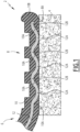
- a part 2 comprises a conductive layer 4 made of an electrically conductive textile and an electrical component 6 having a connection portion 8 welded to the conductive layer 4 so as to fix the electrical component 6 to the conductive layer 4 and to electrically connect the electrical component 6 to the conductive layer 4.
- the textile is made in such a way that the conductive layer 4 is capable of conducting electricity.
- the textile is formed from fibers including conductive fibers made from an electrically conductive material and thermoplastic fibers made from a thermoplastic material.
- the conductive fibers are carbon fibers and/or metal wires, in particular copper wires and/or aluminum wires.
- Carbon is an electrically conductive material.
- the conductive fibers are carbon fibers.
- thermoplastic fibers are polyolefin fibers, polypropylene fibers, polyester fibers, polyethylene terephthalate (PTFE) fibers, polycarbonate (PC) fibers, and/or polymethyl methacrylate (PMMA) fibers.
- PTFE polyethylene terephthalate
- PC polycarbonate
- PMMA polymethyl methacrylate
- thermoplastic fibers are polyolefin fibers, in particular polypropylene fibers.
- the textile is woven.
- the conductive fibers and the thermoplastic fibers are woven together to form a woven textile.
- the textile is non-woven.
- the conductive fibers and the thermoplastic fibers are agglomerated together without being woven.
- the nonwoven fabric is isotropic (the conductive fibers and the thermoplastic fibers have no preferred orientation) or anisotropic (the conductive fibers and the thermoplastic fibers have a preferred orientation).
- the nonwoven fabric is preferably consolidated, i.e. the conductive fibers and the thermoplastic fibers are bonded together.
- the consolidation of the conductive fibers and the thermoplastic fibers is carried out by needling, by pressurizing and/or by heating.
- the needling and pressurizing allows the fibers (i.e. the conductive fibers and the thermoplastic fibers) to be intimately intermingled.
- the heating allows the thermoplastic fibers to be welded together and with the conductive fibers.
- the electrical component 6 comprises a sheath 10 and an electrical conductor 12 extending inside the sheath 10.
- the sheath 10 provides electrical insulation of the electrical conductor 12 from the environment.
- the electrical conductor 12 is received inside the sheath 10 which surrounds the electrical conductor 12.
- the sheath 10 is electrically insulating and made of a thermoplastic material.
- the sheath 10 is made of polypropylene, polyvinyl chloride (PVC), poly(ethylene terephthalate) (PET), polycarbonate (PC) or polymethyl methacrylate (PMMA).
- PVC polyvinyl chloride
- PET poly(ethylene terephthalate)
- PC polycarbonate
- PMMA polymethyl methacrylate
- the sheath 10 is made of a thermoplastic material capable of welding with the thermoplastic material of the thermoplastic fibers of the conductive layer 4.
- the sheath 10 and the thermoplastic fibers of the conductive layer 4 are made of the same thermoplastic material.
- the electrical conductor 12 is for example made of a metallic material, for example copper.
- the electrical conductor 12 is for example a wire or an electrical track.
- the electrical component 6 is for example an insulated electrical wire comprising an electrical conductor 12 in the form of an electrical wire surrounded by the sheath 10.
- the electrical component 6 is for example a flexible electrical sheet comprising an electrical track, the sheath comprising two films, the track being interposed between the two films.
- connection portion 8 welded to the conductive layer 4, the sheath 10 is not removed in the connection portion 8 to perform welding.
- the sheath 10 surrounds the electrical conductor 12 in the connection portion 8.
- connection portion 8 is welded to the conductive layer 4 in such a way that, in the connection portion 8, the sheath 10 is welded to the conductive layer 4 and the electrical conductor 12 is in electrical contact with the conductive layer 4, in particular with the conductive fibers of the conductive layer 4.
- the welding of the sheath 10 to the conductive layer 4 makes it possible to ensure the mechanical connection of the connection portion 8 to the conductive layer 4.
- the contacting of the electrical conductor 12 with the conductive layer 4 makes it possible to ensure the electrical connection of the electrical component 6 to the conductive layer 4.
- the welding of the sheath 10 to the conductive layer 4 is carried out so as to weld the sheath 10 with the conductive layer 4, in particular with the thermoplastic fibers of the conductive layer 4.
- connection portion 8 the sheath 10 is welded to the conductive layer 4 so as to ensure the mechanical connection between the connection portion 8 and the conductive layer 4.
- connection portion 8 is in contact with the conductive layer 4 via a contact surface 8A of the connection portion 8.
- the electrical connection and the mechanical connection between the connection portion 8 and the conductive layer 4 are made via this contact surface 8A.
- connection portion 8 of the electrical component 6 welded to the conductive layer 4 the electrical conductor 12 has one or more contact portion(s) 12A, each contact portion 12A being in contact with the conductive layer 4, and the sheath 10 has one or more connection portion(s) 10A, each connection portion 10A being in contact with the conductive layer 4.
- Each contact portion 12A provides electrical contact between the electrical conductor 12 and the conductive layer 4.
- each contact portion 12A exits the sheath 10 at the interface between the sheath 10 and the conductive layer 4 to come into contact with the conductive layer 4.
- Each contact portion 12A is flush with the contact surface 8A.
- Each connecting portion 10A ensures the mechanical connection between the sheath 10 and the conductive layer 4.
- each connecting portion 10A is in contact with and welded to the conductive layer 4.
- the contact surface 8A of the connection portion 8 in contact with the conductive layer 4 is formed by the contact portion(s) 12A and the connection portion(s) 10A, which are located next to each other.
- the contact portion(s) 12A is (are) contiguous with the connecting portion(s) 10A.
- the contact portion(s) 12A and the connecting portion(s) 10A are located next to each other touching each other, i.e. without empty space between the contact portion(s) 12A and the connecting portion(s) 10A.
- Each contact portion 12A is contiguous with the connecting portion 10A or at least one of the connecting portions 10A.
- Each connecting portion 10A is contiguous with the contact portion 12A or at least one of the contact portions 12A.
- each contact portion 12A is surrounded by one or more connecting portions 10A contiguous to this contact portion 12A.
- connection portion 8 The electrical contact between the electrical conductor 12 and the conductive layer 4 and the mechanical connection between the sheath 10 and the conductive layer 4 are carried out jointly via the connection portion 8, in a contiguous manner.
- the electrical conductor 12 comprises several contact portions 12A spaced apart from each other.
- the contact portions 12A are distributed in a matrix manner.
- the electrical conductor 12 comprises at least one spaced portion 12B, each spaced portion 12B being spaced from the conductive layer 4.
- a connecting portion 10A of the sheath 10 is interposed between each spaced portion 12B of the conductor 12 and the conductive layer 4.
- At least one connecting portion 10A is still present between the electrical conductor 12 and the conductive layer 4.
- the contact portions 12A of the electrical conductor 12 are spaced apart from each other, the spaced portions 12B extending between the contact portions 12A.
- each contact portion 12A of the electrical conductor 12 forms a depression or hollow in the electrical conductor 12, with each spaced portion 12B forming a prominence or bump.
- the electrical conductor 12 thus has a bumpy shape in the connection portion 8.
- connection portion 8 welded to the conductive layer 4
- the electrical conductor 12 is deformed transversely to its extension line inside the sheath 10 so as to be in contact with the conductive layer 4.
- the connecting portion 8 is initially undeformed.
- connection portion 8 has a substantially circular cross-section before welding, the electrical conductor 12 being located in the center and being completely surrounded by the sheath 10 located at the periphery.
- connection portion 8 has the shape of a flat strip before welding, the electrical conductor 12 having the shape of a conductive track sandwiched between two films defining the sheath 10.
- the welding is carried out for example using a welding head 14 comprising a welding surface 16 intended to be applied to the connection portion 8 of the electrical component 6 so as to press it against the conductive layer 4, the welding head 14 optionally comprising one or more protrusion(s) 18 projecting from the welding surface 16.
- connection portion 8 is applied against the conductive layer 4 ( Figure 2 ).
- the connection portion 8 is in contact with the conductive layer 4 via the sheath 10.
- a portion of the sheath 10 is initially interposed between the electrical conductor 12 and the conductive layer 4.
- connection portion 8 When welding ( Figure 3 ), the welding head 14 is pressed against the connection portion 8.
- the welding surface 16 presses the connection portion 8 against the conductive layer 4, which presses the sheath 10 against the conductive layer 4 and ensures the welding of the sheath 10 on the conductive layer 4.
- the welding is carried out in such a way that the sheath 10 is welded to the conductive layer 4, the electrical conductor 12 being placed in electrical contact with the conductive layer 4.
- the welding is carried out in such a way that the electrical conductor 12 is deformed to form each contact portion 12A emerging from the sheath 10 to come into contact with the conductive layer 4.
- each protrusion 18 is locally introduced into the sheath 10 and locally pushes the electrical conductor 12 towards the conductive layer 4, such that the electrical conductor 12 is deformed by forming the contact portion(s) 12A, the electrical conductor 12 is brought into contact with the conductive layer 4.
- the electrical conductor 12 is locally pushed by each protrusion 18 inside the sheath 10 during welding, towards the conductive layer 4, so that it comes into contact with the conductive layer 4, and in particular with the conductive fibers of the textile forming the conductive layer 4.
- the electrical conductor 12 is then electrically connected to the conductive layer 4 ( Figure 3 ).
- the sheath 10 is crushed between the welding surface 16 and the conductive layer 4 and the material of the sheath 10 is partly pushed towards the periphery of the welding surface 16.
- the sheath 10 forms for example a peripheral bead 10B at the periphery of the connection portion 8 welded to the conductive layer 4, as illustrated on the right in the Figures 1 And 3 .
- connection portion 8 due to the welding, the material of the portion of the sheath 10 located between the electrical conductor 12 and the conductive layer 4 is at least partly driven away, so that the electrical conductor 12 comes into contact with the conductive layer 4.
- the material of the sheath 10 is expelled from the area located between each contact portion 12A, deformed during welding to be brought into contact with the conductive layer 4, and the conductive layer 4.
- each contact portion 12A exits the sheath 10 on the contact surface 8A of the connection portion 8 to come into contact with the conductive layer 4.
- the sheath 10 remains present around each contact portion 12A by forming one or more connecting portions 10A surrounding the contact portion 12A with which it(they) is(are) contiguous.
- one or more protrusion(s) 18 makes it possible to locally deform the electrical conductor 12 so that it comes into contact with the conductive layer 4, without completely removing the portion of the sheath 10 initially present between the electrical conductor 12 and the conductive layer 4.
- Each protrusion 18 makes it possible, for example, to form a contact portion 12A.
- Each contact portion 12A corresponds to a protrusion 18.
- Each protrusion 18 has geometric characteristics suitable for ensuring contact between the electrical conductor 12 and the conductive layer 4 during welding.
- each protrusion 18 has a height (taken along the normal N to the welding surface 16) greater than half the thickness of the connection portion 8 before welding and/or less than four times the thickness of the connection portion 8 before welding.
- protrusions 18 are preferably distributed on the welding surface 16 so as to promote contact between the electrical conductor 12 and the conductive layer 4 during welding, while achieving satisfactory welding of the sheath 10 on the conductive layer 4.
- each protrusion 18 has a transverse dimension and is spaced from each other adjacent protrusion 18 by a spacing distance.
- each protrusion 18 along at least one transverse direction is substantially equal to the spacing between the protrusions along said transverse dimension.
- the protrusions 18 are distributed over the welding surface 16 while being aligned in a first transverse direction T1 and in a second transverse direction T2.
- the transverse dimension D1 of each protrusion 18 along the first transverse direction T1, the spacing E1 between the protrusions 18 along the first transverse direction T1, the transverse dimension D2 of each protrusion 18 along the second transverse direction T2 and the spacing E2 between the protrusions 18 along the second transverse direction T2 are substantially equal.
- the transverse dimension D1 of each protrusion 18 along the first transverse direction T1 and/or the transverse dimension D2 of each protrusion 18 along the second transverse direction T2 is (are) greater than one twentieth of the thickness of the connection portion 8 before welding and/or less than the thickness of the connection portion 8 before welding.
- the spacing E1 between the adjacent protrusions 18 along the first transverse direction T1 and/or the spacing E2 between the adjacent protrusions 18 along the second transverse direction T2 is (are) greater than one twentieth of the thickness of the connection portion 8 before welding and/or less than the thickness of the connection portion 8 before welding.
- the thickness of the connection portion 8 before welding corresponds to the diameter of the electrical component 6.
- connection portion 8 is welded to the conductive layer 4, for example by ultrasonic welding.
- the welding head 14 is an ultrasonic welding head or “sonotrode”.
- the welding head 14 is connected to an ultrasonic generator (not shown) for the generation of ultrasound in the welding head 14 applied against the connection portion 8, itself applied to the conductive layer 4.
- a method of manufacturing the part 2 comprises providing a conductive layer 4 made of an electrically conductive textile, applying the portion of connection 8 of the electrical component 6 against the conductive layer 4, and welding the connection portion 8 of the electrical component 6 onto the conductive layer 4, for example by ultrasonic welding, in particular using a welding head 14 as described above.
- the conductive layer 4, on which the connection portion 8 of the electrical component 6 is fixed and electrically connected, is, for example, fixed to a support.
- the support is made of a composite material comprising reinforcing fibers, preferably natural reinforcing fibers, in particular flax fibers, hemp fibers, kenaf fibers and/or wood fibers, embedded in a matrix, preferably a thermoplastic matrix, in particular a polypropylene matrix.
- reinforcing fibers preferably natural reinforcing fibers, in particular flax fibers, hemp fibers, kenaf fibers and/or wood fibers, embedded in a matrix, preferably a thermoplastic matrix, in particular a polypropylene matrix.
- a material comprising natural fibres embedded in a polypropylene matrix is also known by the acronym NFPP for "Natural Fibre PolyPropylene" in English.
- the conductive layer 4 can be easily assembled with such a support due to the presence of thermoplastic fibers in the textile forming the conductive layer 4, which can bond with the thermoplastic matrix of the support, for example by pressing, optionally with heating.
- the part 2 may comprise a conductive layer 4 or several conductive layers 4. Each conductive layer 4 may be associated with an electrical component 6 or several electrical components 6, each electrical component 6 having a connection portion 8 welded to the associated conductive layer 4.
- the part 2 comprises one or more conductive layers 4, each conductive layer 4 being associated with at least one electrical component 6 having a connection portion 8 welded onto this conductive layer 4.
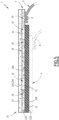
- the part 2 comprises a laminate 20 formed of several superimposed layers including the conductive layer 4 and, in addition, a support layer 22.
- the laminate 20 has a front face 20A intended to be visible and a rear face 20B opposite the front face 20A.
- the support layer 22 defines a support.
- the support layer 22 gives the laminate 4 its shape, as well as its mechanical characteristics, in particular its rigidity.
- the support layer 22 is for example made of a plastic material or a composite material.
- the support layer 22 is made of a composite material comprising natural fibers embedded in a matrix of material plastic, in particular a polypropylene matrix.
- Natural fibres include, for example, flax fibres, hemp fibres, kenaf fibres and/or wood fibres.
- the support layer 22 has, for example, a planar shape or a three-dimensional shape with raised areas.
- the support layer 22 comprises, for example, an area projecting relative to the remainder of the support layer 22 to form an armrest.
- the support layer 22 is, for example, formed by injection molding in a molding cavity having the desired shape of the support layer.
- the support layer 22 has a front face 22A facing the front face 20A of the laminate 20, and a rear face 22B opposite its front face 22A.
- the laminate comprises a decorative layer 24.
- the decorative layer 24 defines, for example, the front face 20A of the laminate 20, intended to be visible.
- the decorative layer 24 covers at least part of the front face 22A of the support layer 22. In an exemplary embodiment, the decorative layer 24 completely covers the front face 22A of the support layer 22.
- the decorative layer 24 comprises a front face 24A facing away from the support layer 22 and a rear face 24B facing towards the support layer 22.
- the decorative layer 24 gives its appearance and/or feel to the part 2.
- the decorative layer 24 is made of a material having a particular appearance and/or feel that it is desired to give to the motor vehicle part 2.
- the decorative layer 24 is for example made of textile material, plastic material, wood material, leather, imitation leather or other.
- the decorative layer 24 is shaped to the support layer 22, that is to say that it substantially matches the shape of the front face 22A of the support layer 22, in the area of the front face 22A of the support layer 22 that the decorative layer 24 covers.
- the front face 24A of the decorative layer 24 may include indications intended for a user, for example to indicate the presence of a functional zone, as will be described later.
- the decorative layer 24 is translucent, at least in certain translucent areas allowing light to pass from the rear face 24B to the front face 24A of the decorative layer 24. This makes it possible to backlight these areas in order to inform a user of the presence of a functional area for example.
- the conductive layer 4 makes it possible to create functional electrical circuits integrated into the laminate 20.
- the conductive layer 4 comprises at least one pattern 26 formed by at least one conductive zone 28 formed by the conductive layer 4. and at least one non-conductive area 30, each conductive area 28 of the pattern 26 being a solid area of the conductive layer 4 and each non-conductive area 30 of the pattern 26 being formed by a through opening 32 formed through the conductive layer 4.
- Each pattern 26 has shapes adapted to define a functional electrical circuit performing a particular function when each conductive zone 28 of the pattern 26 is supplied with electricity via an electrical component 6 welded to the conductive layer 4.
- the function performed by the functional electrical circuit is a function of interaction with a user on the front face 20A of the laminate 20.
- the functional electrical circuit is configured to provide a human-machine interface, a user being able to interact with the front face 20A of the laminate 20 to activate, control and/or influence a function performed by a machine connected to the conductive layer 4 via an electrical component 6.
- the functional electrical circuit is for example a resistive circuit or a capacitive circuit capable of detecting the contact and/or proximity of a user's finger with the front face 20A of the laminate 20 at the level of the functional electrical circuit formed by the pattern 18.
- each pattern 26 defines for example a touch button, a touch slider or a touch surface, in particular a multi-point touch surface defining several interaction points.
- the functional electrical circuit is for example a heating resistive circuit. This makes it possible to produce a heating motor vehicle part 2, i.e. integrating a heating function.
- Each pattern 26 is connected to an electrical source via an electrical component 6 welded onto the conductive layer 4 for its electricity supply.
- a conductive layer 4 is provided with a pattern 26 or several patterns 26.
- An electrical component 6 makes it possible to connect a pattern 26 or several patterns 26 of a conductive layer 4 to an electrical source.
- the laminate 20 comprises one or more conductive layers 4, each conductive layer 4 being associated with at least one electrical component 6 having a connection portion 8 welded to this conductive layer 4.
- each conductive layer 4 comprises at least one pattern 26 defining a functional electrical circuit.
- the laminate 20 comprises a conductive layer 4 arranged on the front face of the layer of support 22, and in particular, where appropriate, a conductive layer 4 interposed between the support layer 22 and the decorative layer 24.
- the laminate comprises a conductive layer 4 covering the rear face 22B of the support layer 22.
- the laminate 20 comprises for example a single conductive layer 4 arranged on the front face 22A of the support layer 22, a single conductive layer 4 arranged on the rear face 22B of the support layer 22, or two conductive layers 4.
- the laminate 20 comprises two conductive layers 4, and preferably, these conductive layers 4 are located on either side of the support layer 22, which is sandwiched between the two conductive layers 4. Each conductive layer 4 is preferably in contact with a respective face of the support layer 22.
- An exemplary embodiment with two conductive layers 4 is particularly suitable for producing a capacitive sensor using two functional electrical circuits, each functional electrical circuit being formed in a respective conductive layer 4 among the two conductive layers 4, the two electrical circuits being superimposed.
- a capacitive sensor makes it possible to detect a contact and/or the proximity of a user's finger.
- Each conductive layer 4 is fixed to the support layer 20, for example by applying the conductive layer 4 against the support layer 20 with pressure and/or heating.
- the support layer 22 is made of a thermoplastic material or comprises a thermoplastic matrix, this makes it possible to obtain adhesion between the thermoplastic matrix of the support layer 22 and the thermoplastic fibers of the conductive layer 4.
- Adhesion is particularly good when the thermoplastic fibres and the thermoplastic material or thermoplastic matrix are made of the same material, for example polypropylene.
- each conductive layer 4 is fixed to the support layer 22 by gluing, using a layer of glue interposed between the conductive layer 4 and the support layer 22.
- Each conductive layer 4 made of a textile formed of conductive fibers and thermoplastic fibers and applied against the support layer 22 to obtain the laminate 20, reinforces the support layer 22 and thus defines a reinforcement layer.
- a method of manufacturing the part 2 comprises providing a support layer 22, providing at least one conductive layer 4, and assembling the support layer 22 with each conductive layer 4 to form a laminate 20, for example by pressurizing and/or heating.
- the manufacturing method comprises the production of each pattern 26 in each conductive layer 4, and providing one or more through opening(s) 32 through this conductive layer 4.
- Each through opening 32 formed in a conductive layer 4 is hollowed out over the entire thickness of this conductive layer 4, for example by laser machining, by mechanical machining and/or by chemical attachment.
- each pattern 26 in each conductive layer 4 is carried out after application and fixing of the conductive layer 4 on the support layer 22.
- the manufacturing method comprises, where appropriate, the assembly of the decorative layer 24, for example on the front face 22A of the support layer 22 or on a conductive layer 4 covering the front face 22A of the support layer 22.
- the fixing is carried out for example by gluing.
- the invention is not limited to the exemplary embodiments and variants described above.
- the electrical conductor 12 is in contact with the conductive layer 4, the sheath 10 extending on the side of the electrical conductor 12 opposite the conductive layer 4 and covering the electrical conductor 12.
- the part of the electrical conductor 12 opposite the conductive layer 4 in the electrical contact portions 12A is not covered with sheath 10.
Landscapes
- Engineering & Computer Science (AREA)
- Mechanical Engineering (AREA)
- Textile Engineering (AREA)
- Manufacturing & Machinery (AREA)
- Laminated Bodies (AREA)
Description
- La présente invention concerne une pièce, qui peut être par exemple une pièce de de garnissage de véhicule automobile, et un procédé de fabrication d'une telle pièce.
- Il est possible de réaliser une pièce de garnissage de véhicule automobile comprenant un stratifié possédant une couche de décor, destinée à être visible, et une couche de support, conférant sa forme à la pièce de garnissage, la couche de support étant réalisée en un matériau composite comprenant des fibres naturelles noyées dans une matrice en matière plastique.
- L'utilisation de fibres naturelles permet de fournir une pièce de garnissage allégée et de réduire l'impact environnemental.
- Il est possible d'intégrer à la pièce de garnissage certaines fonctionnalités à destination des utilisateurs du véhicule, ces fonctionnalités étant accessibles via une surface externe de la pièce de garnissage.
- Ainsi, la surface externe de la pièce de garnissage comprend par exemple des zones tactiles pour permettre de piloter certaines fonctions du véhicule.
- Des éléments fonctionnels permettant de réaliser ces fonctionnalités, tels que des circuits imprimés, sont par exemple intégrés dans la pièce de garnissage, sous la couche de décor, afin de ne pas être visibles par l'utilisateur.
- Les éléments fonctionnels sont par exemple collés sur la couche de support avant qu'elle ne soit recouverte par la couche de décor.
- Un tel procédé est cependant fastidieux et peut être compliqué, notamment lorsque plusieurs zones tactiles sont prévues, divers éléments fonctionnels devant alors être fixés en divers endroits de la couche de support.
- En outre, en cas de mauvais positionnement du ou des élément(s) fonctionnel(s) sur la couche de support et par rapport à la couche de décor, la qualité de la pièce de garnissage est dégradée, par exemple parce que les zones tactiles ne s'étendent pas exactement en regard d'indications prévues sur la surface externe de la pièce de garnissage pour indiquer leur présence et leur position.
-
US2017/245326A1 divulgue une structure laminée pour revêtement de sol chauffant comprenant une couche décorative et une sous-couche entre lesquelles sont disposés une couche conductrice comprenant des fibres de verre et des fibres de carbone, des conducteurs disposés sur la couche conductrice, et des couches isolantes disposées de part et d'autre de la couche conductrice. - Un des buts de l'invention est de proposer une pièce, par exemple une pièce de garnissage de véhicule automobile, qui puisse être munie de fonctionnalités de manière simple et fiable.
- A cet effet, l'invention propose une pièce selon la revendication 1.
- L'inclusion dans la pièce d'une couche conductrice réalisée dans un textile conducteur d'électricité permet d'exploiter les propriétés de conduction électrique du textile pour ajouter des fonctionnalités à la pièce.
- Le textile, qui comprend des fibres conductrices réalisées dans un matériau conducteur d'électricité, par exemple des fibres de carbones, et des fibres thermoplastiques réalisées dans un matériau thermoplastique, permet d'assurer la conduction électrique tout en facilitant la fixation du composant électrique sur la couche conductrice et la connexion électrique du conducteur électrique du composant électrique à la couche conductrice.
- En particulier, la gaine réalisée en un matériau thermoplastique et les fibres thermoplastiques du textile peuvent être soudées ensemble ce qui assure la liaison mécanique du composant électrique sur la couche conductrice, et le conducteur électrique du composant électrique peut être mis en contact avec les fibres conductrices du textile lors du soudage. La liaison mécanique et la connexion électrique peuvent être réalisées simultanément lors de l'opération de soudage.
- La présence d'une ou plusieurs portions de contact et d'une ou plusieurs portions de liaison contiguës, i.e. qui sont disposées côtes à côte en se touchant par leurs bords, permet d'assurer un contact électrique et une liaison mécanique fiables.
- Des caractéristiques optionnelles de la pièce sont définies aux revendications 2 à 10.
- L'invention propose aussi un procédé de fabrication selon la revendication 11.
- Des caractéristiques optionnelles du procédé de fabrication sont définies aux revendications 12 à 15.
- L'invention et ses avantages seront mieux compris à la lecture de la description qui va suivre, donnée uniquement à titre d'exemple non limitatif, et faite en référence aux dessins annexés, sur lesquels :
- la
Figure 1 illustre une pièce comprenant un composant électrique soudé sur une couche conductrice réalisée dans un textile conducteur d'électricité ; - les
Figures 2 et3 illustrent le soudage du composant électrique sur la couche conductrice réalisée dans un textile conducteur d'électricité, pour la fabrication de la pièce de laFigure 1 ; - la
Figure 4 est une vue de face d'une tête de soudage utilisable pour le soudage du composant électrique sur la couche conductrice d'électricité ; et - la
Figure 5 est une vue schématique en coupe d'une pièce comprenant un stratifié intégrant la couche conductrice muni du composant électrique. - Comme illustré sur la
Figure 1 , une pièce 2 comprend une couche conductrice 4 réalisée dans un textile conducteur d'électricité et un composant électrique 6 ayant une portion de connexion 8 soudée sur la couche conductrice 4 de manière à fixer le composant électrique 6 sur la couche conductrice 4 et à raccorder électriquement le composant électrique 6 à la couche conductrice 4. - Le textile est réalisé de manière que la couche conductrice 4 est propre à conduire l'électricité.
- Le textile est formé de fibres comprenant des fibres conductrices réalisées dans un matériau conducteur d'électricité et des fibres thermoplastiques réalisées dans un matériau thermoplastique.
- Dans un exemple de réalisation, les fibres conductrices sont des fibres de carbone et/ou des fils métalliques, en particulier des fils de cuivre et/ou des fils d'aluminium. Le carbone est un matériau conducteur d'électricité.
- Dans un exemple de réalisation particulier, les fibres conductrices sont des fibres de carbone.
- Dans un exemple de réalisation, les fibres thermoplastiques sont des fibres de polyoléfine, des fibres de polypropylène, des fibres de polyester, de fibres de polyéthylène téréphtalate (PTFE), des fibres de polycarbonate (PC) et/ou des fibres de polyméthacrylate de méthyle (PMMA).
- Dans un exemple de réalisation particulier, les fibres thermoplastiques sont des fibres de polyoléfine, en particulier des fibres de polypropylène.
- Dans un exemple de réalisation, le textile est tissé. Dans ce cas, les fibres conductrices et les fibres thermoplastiques sont tissées entre elle pour former un textile tissé.
- Dans un autre exemple de réalisation préféré, le textile est non-tissé. Dans ce cas, les fibres conductrices et les fibres thermoplastiques sont agglomérées entre elles sans être tissées.
- Le textile non-tissé est isotrope (les fibres conductrices et les fibres thermoplastiques ne présentent aucune orientation privilégiée) ou anisotrope (les fibres conductrices et les fibres thermoplastiques présentent une orientation privilégiée).
- Le textile non-tissé est de préférence consolidé, i.e. les fibres conductrices et les fibres thermoplastiques sont liées entre elles.
- Dans un exemple de réalisation, la consolidation des fibres conductrices et des fibres thermoplastiques est réalisée par aiguilletage, par mise sous pression et/ou par chauffage. L'aiguilletage et la mise sous pression permet d'entremêler intimement les fibres (i.e. les fibres conductrices et les fibres thermoplastiques). Le chauffage permet un soudage des fibres thermoplastiques entre elles et avec les fibres conductrices.
- Le composant électrique 6 comprend une gaine 10 et un conducteur électrique 12 s'étendant à l'intérieur de la gaine 10.
- La gaine 10 assure l'isolation électrique du conducteur électrique 12 vis-à-vis de l'environnement. Le conducteur électrique 12 est reçu à l'intérieur de la gaine 10 qui entoure le conducteur électrique 12.
- La gaine 10 est isolante électriquement et réalisée dans un matériau thermoplastique.
- Dans un exemple de réalisation, la gaine 10 est réalisée en polypropylène, en polychlorure de vinyle (PVC), en poly(téréphtalate d'éthylène) (PET), en polycarbonate (PC) ou en polyméthacrylate de méthyle (PMMA).
- De préférence, la gaine 10 est réalisée dans un matériau thermoplastique propre à se souder avec le matériau thermoplastique des fibres thermoplastiques de la couche conductrice 4.
- En particulier, dans un exemple de réalisation, la gaine 10 et les fibres thermoplastiques de la couche conductrice 4 sont réalisées dans le même matériau thermoplastique.
- Le conducteur électrique 12 est par exemple réalisé dans un matériau métallique, par exemple du cuivre. Le conducteur électrique 12 est par exemple un fil ou une piste électrique.
- Le composant électrique 6 est par exemple un fil électrique isolé comprenant un conducteur électrique 12 sous la forme d'un fil électrique entouré par la gaine 10. En variante, le composant électrique 6 est par exemple une nappe électrique flexible comprenant une piste électrique, la gaine comprenant deux films, la piste étant intercalée entre les deux films.
- Dans la portion de connexion 8 soudée sur la couche conductrice 4, la gaine 10 n'est pas retirée dans la portion de connexion 8 pour réaliser le soudage. Lors du soudage de la portion de connexion 8 sur la couche conductrice 4, la gaine 10 entoure le conducteur électrique 12 dans la portion de connexion 8.
- La portion de connexion 8 est soudée sur la couche conductrice 4 de telle manière que, dans la portion de connexion 8, la gaine 10 est soudée à la couche conductrice 4 et le conducteur électrique 12 est en contact électrique avec la couche conductrice 4, en particulier avec les fibres conductrices de la couche conductrice 4.
- Le soudage de la gaine 10 à la couche conductrice 4 permet d'assurer la liaison mécanique de la portion de connexion 8 à la couche conductrice 4. La mise en contact du conducteur électrique 12 avec la couche conductrice 4 permet d'assurer le raccordement électrique du composant électrique 6 à la couche conductrice 4. Le soudage de la gaine 10 à la couche conductrice 4 est réalisé de manière à souder la gaine 10 avec la couche conductrice 4, en particulier avec les fibres thermoplastiques de la couche conductrice 4.
- Dans la portion de connexion 8, la gaine 10 est soudée à la couche conductrice 4 de manière à assurer la liaison mécanique entre la portion de connexion 8 et la couche conductrice 4.
- La portion de connexion 8 est en contact avec la couche conductrice 4 par une surface de contact 8A de la portion de connexion 8. La connexion électrique et la liaison mécanique entre la portion de connexion 8 et la couche conductrice 4 sont réalisées via cette surface de contact 8A.
- Dans la portion de connexion 8 du composant électrique 6 soudée sur la couche conductrice 4, le conducteur électrique 12 possède un ou des portion(s) de contact 12A, chaque portion de contact 12A étant en contact avec la couche conductrice 4, et la gaine 10 possède un ou des portion(s) de liaison 10A, chaque portion de liaison 10A étant en contact avec la couche conductrice 4.
- Chaque portion de contact 12A assure le contact électrique entre le conducteur électrique 12 et la couche conductrice 4. En particulier, chaque portion de contact 12A sort de la gaine 10 à l'interface entre la gaine 10 et la couche conductrice 4 pour venir en contact avec la couche conductrice 4. Chaque portion de contact 12A affleure la surface de contact 8A.
- Chaque portion de liaison 10A assure la liaison mécanique entre la gaine 10 et la couche conductrice 4. En particulier, chaque portion de liaison 10A est en contact avec et soudée sur la couche conductrice 4.
- La surface de contact 8A de la portion de connexion 8 en contact avec la couche conductrice 4 est formée par la(les) portion(s) de contact 12A et la(les) portion(s) de liaison 10A, qui sont situées les unes à côtés des autres.
- La(les) portion(s) de contact 12A est(sont) contiguë(s) avec la(les) portion(s) de liaison 10A.
- En d'autres termes, la(les) portion(s) de contact 12A et la(les) portions(s) de liaison 10A sont situées les unes à côtés des autres en se touchant, i.e. sans espace vide entre la(les) portion(s) de contact 12A et la(les) portion(s) de liaison 10A
- Chaque portion de contact 12A est contiguë avec la portion de liaison 10A ou au moins une parmi les portions de liaison 10A. Chaque portion de liaison 10A est contiguë avec la portion de contact 12A ou au moins une parmi les portions de contact 12A.
- En particulier, chaque portion de contact 12A est entourée par une ou plusieurs portions de liaison 10A contiguë(s) à cette portion de contact 12A.
- Le contact électrique entre le conducteur électrique 12 et la couche conductrice 4 et la liaison mécanique entre la gaine 10 et la couche conductrice 4 sont réalisées conjointement via la portion de connexion 8, de manière contiguë.
- Dans un exemple de réalisation particulier, le conducteur électrique 12 comprend plusieurs portions de contact 12A écartées les unes des autres.
- Dans un exemple de réalisation, les portions de contact 12A sont réparties de manière matricielle.
- Dans un exemple de réalisation, dans la portion de connexion 8 soudée sur la couche conductrice 4, le conducteur électrique 12 comprend au moins une portion écartée 12B, chaque portion écartée 12B étant écartée de la couche conductrice 4.
- Une portion de liaison 10A de la gaine 10 est interposée entre chaque portion écartée 12B du conducteur 12 et la couche conductrice 4.
- Ainsi, dans un tel mode de réalisation, au moins une portion de liaison 10A est encore présente entre le conducteur électrique 12 et la couche conductrice 4.
- Dans un exemple de réalisation, les portions de contact 12A du conducteur électrique 12 sont espacées les unes des autres, les portions écartées 12B s'étendant entre les portions de contact 12A.
- Dans la portion de connexion 8, chaque portion de contact 12A du conducteur électrique 12 forme une dépression ou un creux dans le conducteur électrique 12, chaque portion écartée 12B formant une proéminence ou une bosse.
- Le conducteur électrique 12 présente ainsi dans la portion de connexion 8, une forme bosselée.
- Les
Figures 2 et3 illustrent le soudage de la portion de connexion 8 du composant électrique 6 sur la couche conductrice 4. - Comme visible sur ces
Figures 2 et3 , dans la portion de connexion 8 soudée sur la couche conductrice 4, le conducteur électrique 12 est déformé transversalement à sa ligne d'extension à l'intérieur de la gaine 10 de manière à être en contact avec la couche conductrice 4. - La portion de connexion 8 est initialement non déformée.
- Dans le cas d'un composant électrique 6 qui est un fil électrique gainé, la portion de connexion 8 présente avant soudage une section transversale sensiblement circulaire, le conducteur électrique 12 étant situé au centre et étant complètement entouré par la gaine 10 situé à la périphérie.
- Dans le cas d'un composant électrique 6 qui est une nappe électrique, la portion de connexion 8 présente avant soudage la forme d'une bande plate, le conducteur électrique 12 ayant la forme d'une piste conductrice prise en sandwich entre deux films définissant la gaine 10.
- Le soudage est réalisé par exemple à l'aide d'une tête de soudage 14 comprenant une surface de soudage 16 destinée à être appliquée sur la portion de connexion 8 du composant électrique 6 de manière à la presser contre la couche conductrice 4, la tête de soudage 14 comprenant en option une ou plusieurs protrusion(s) 18 en saillie de la surface de soudage 16.
- En vue du soudage, la portion de connexion 8 est appliquée contre la couche conductrice 4 (
Figure 2 ). La portion de connexion 8 est en contact avec la couche conductrice 4 par l'intermédiaire de la gaine 10. Une partie de la gaine 10 est initialement interposée entre le conducteur électrique 12 et la couche conductrice 4. - Lors du soudage (
Figure 3 ), la tête de soudage 14 est pressée contre la portion de connexion 8. La surface de soudage 16 presse la portion de connexion 8 contre la couche conductrice 4, ce qui presse la gaine 10 contre la couche conductrice 4 et assure le soudage de la gaine 10 sur la couche conductrice 4. - Le soudage est réalisé de manière que la gaine 10 est soudée sur la couche conductrice 4, le conducteur électrique 12 étant mis en contact électrique avec la couche conductrice 4.
- En particulier, le soudage est réalisé de telle manière que le conducteur électrique 12 est déformé pour former chaque portion de contact 12A sortant de la gaine 10 pour venir en contact avec la couche conductrice 4.
- Le cas échéant, chaque protrusion 18 s'introduit localement dans la gaine 10 et enfonce localement le conducteur électrique 12 vers la couche conductrice 4, de telle manière que le conducteur électrique 12 est déformé en formant la(les) portion(s) de contact 12A, le conducteur électrique 12 est mis en contact avec la couche conductrice 4.
- Le conducteur électrique 12 est localement poussé par chaque protrusion 18 à l'intérieur de la gaine 10 lors du soudage, vers la couche conductrice 4, de sorte qu'il vient en contact avec la couche conductrice 4, et en particulier avec les fibres conductrices du textile formant la couche conductrice 4. Le conducteur électrique 12 est alors raccordé électriquement à la couche conductrice 4 (
Figure 3 ). - La gaine 10 est écrasée entre la surface de soudage 16 et la couche conductrice 4 et la matière de la gaine 10 est en partie chassée vers la périphérie de la surface de soudage 16.
- La gaine 10 forme par exemple un bourrelet périphérique 10B à la périphérie de portion de connexion 8 soudée sur le couche conductrice 4, comme illustré à droite sur les
Figures 1 et3 . - Dans la portion de connexion 8, du fait du soudage, la matière de la portion de la gaine 10 située entre le conducteur électrique 12 et la couche conductrice 4 est au moins en partie chassée, de sorte que le conducteur électrique 12 vient en contact avec la couche conductrice 4.
- En particulier, la matière de la gaine 10 est chassée de la zone située entre chaque portion de contact 12A, déformée lors du soudage pour être mise en contact avec la couche conductrice 4, et la couche conductrice 4.
- A l'issue du soudage, chaque portion de contact 12A sort de la gaine 10 sur la surface de contact 8A de la portion de connexion 8 pour venir en contact avec la couche conductrice 4.
- La gaine 10 reste présente autour de chaque portion de contact 12A en formant une ou plusieurs portions de liaison 10A entourant la portion de contact 12A avec laquelle elle(s) est(sont) contiguë(s).
- La prévision d'une ou plusieurs protrusion(s) 18 permet de déformer localement le conducteur électrique 12 pour qu'il vienne en contact avec la couche conductrice 4, sans chasser complètement la portion de la gaine 10 initialement présente entre le conducteur électrique 12 et la couche conductrice 4.
- Chaque protrusion 18 permet par exemple de former une portion de contact 12A. Chaque portion de contact 12A correspond à une protrusion 18.
- Chaque protrusion 18 présente des caractéristiques géométriques appropriées pour assurer la mise en contact du conducteur électrique 12 avec la couche conductrice 4 lors du soudage.
- De préférence, chaque protrusion 18 présente une hauteur (prise suivant la normale N à la surface de soudage 16) supérieure à la moitié de l'épaisseur de la portion de connexion 8 avant soudage et/ou inférieure au quadruple de l'épaisseur de la portion de connexion 8 avant soudage.
- Lorsque plusieurs protrusions 18 sont prévues, elles sont de préférence réparties sur la surface de soudage 16 de manière à favoriser la mise en contact du conducteur électrique 12 avec la couche conductrice 4 lors du soudage, tout en réalisant un soudage satisfaisant de la gaine 10 sur la couche conductrice 4.
- Suivant au moins une direction transversale perpendiculaire à la normale N à la surface de soudage 16, chaque protrusion 18 présente une dimension transversale et est écartés de chaque autre protrusion 18 adjacente d'une distance d'écartement.
- De préférence, la dimension transversale de chaque protrusion 18 selon au moins une direction transversale est sensiblement égale à l'écartement entre les protrusions suivant ladite dimension transversale.
- Comme illustré sur la
Figure 5 , dans un exemple de réalisation, les protrusions 18 sont réparties sur la surface de soudage 16 en étant alignées suivant une première direction transversale T1 et suivant une deuxième direction transversale T2. - De préférence, la dimension transversale D1 de chaque protrusion 18 selon la première direction transversale T1, l'écartement E1 entre les protrusions 18 suivant la première direction transversale T1, la dimension transversale D2 de chaque protrusion 18 selon la deuxième direction transversale T2 et l'écartement E2 entre les protrusions 18 suivant la deuxième direction transversale T2 sont sensiblement égaux.
- Dans un exemple de réalisation, la dimension transversale D1 de chaque protrusion 18 selon la première direction transversale T1 et/ou la dimension transversale D2 de chaque protrusion 18 selon la deuxième direction transversale T2 est(sont) supérieure(s) au vingtième de l'épaisseur de la portion de connexion 8 avant soudage et/ou inférieure(s) à l'épaisseur de la portion de connexion 8 avant soudage.
- Dans un exemple de réalisation, l'écartement E1 entre les protrusions 18 adjacentes selon la première direction transversale T1 et/ou l'écartement E2 entre les protrusions 18 adjacentes selon la deuxième direction transversale T2 est(sont) supérieur(s) au vingtième de l'épaisseur de la portion de connexion 8 avant soudage et/ou inférieure(s) à l'épaisseur de la portion de connexion 8 avant soudage.
- Lorsque le composant électrique 6 est un fil électrique, de section circulaire, l'épaisseur de la portion de connexion 8 avant soudage correspondant au diamètre du composant électrique 6.
- La portion de connexion 8 est soudée sur la couche conductrice 4 par exemple par soudage par ultrasons. Dans ce cas, la tête de soudage 14 est une tête de soudage par ultrasons ou « sonotrode ».
- De manière connue, pour le soudage par ultrasons, la tête de soudage 14 est reliée à une générateur d'ultrasons (non représenté) pour la génération d'ultrasons dans la tête de soudage 14 appliquée contre la portion de connexion 8, elle-même appliquée sur la couche conductrice 4.
- Un procédé de fabrication de la pièce 2 comprend la fourniture d'une couche conductrice 4 réalisée dans un textile conducteur d'électricité, l'application de la portion de connexion 8 du composant électrique 6 contre la couche conductrice 4, et le soudage de la portion de connexion 8 du composant électrique 6 sur la couche conductrice 4, par exemple par soudage par ultrasons, en particulier à l'aide d'une tête de soudage 14 telle que décrite ci-dessus.
- La couche conductrice 4, sur laquelle est fixée et raccordée électriquement la portion de connexion 8 du composant électrique 6 est, par exemple fixée sur un support.
- Avantageusement, le support est réalisé dans un matériau composite comprenant des fibres de renfort, de préférences des fibres de renfort naturelles, en particulier des fibres de lin, des fibres de chanvre, des fibres de kénaf et/ou des fibres de bois, noyées dans une matrice, de préférence une matrice thermoplastique, en particulier une matrice en polypropylène.
- Un matériau comprenant des fibres naturelles noyées dans une matrice ne polypropylène est également connu sous l'acronyme NFPP pour « Natural Fibre PolyPropylene » en anglais.
- La couche conductrice 4 peut être facilement assemblée avec un tel support du fait de la présence de fibres thermoplastiques dans le textile formant la couche conductrice 4, qui peuvent se lier avec la matrice thermoplastique du support, par exemple par pressage, optionnellement avec chauffage.
- La pièce 2 peut comprendre une couche conductrice 4 ou plusieurs couches conductrices 4. Chaque couche conductrice 4 peut être associée à un composant électrique 6 ou plusieurs composants électriques 6, chaque composant électrique 6 ayant une portion de connexion 8 soudée sur la couche conductrice 4 associée.
- De manière générale, la pièce 2 comprend une ou plusieurs couches conductrices 4, chaque couche conductrice 4 étant associée à au moins un composant électrique 6 possédant une portion de connexion 8 soudée sur cette couche conductrice 4.
- Comme illustré sur la
Figure 5 , dans un exemple de réalisation particulier, la pièce 2 comprend un stratifié 20 formé de plusieurs couches superposées incluant la couche conductrice 4 et, en outre, une couche de support 22. - Le stratifié 20 possède une face avant 20A destinée à être visible et une face arrière 20B opposée à la face avant 20A.
- La couche de support 22 définit un support. La couche de support 22 confère sa forme au stratifié 4, ainsi que ses caractéristiques mécaniques, notamment sa rigidité.
- La couche de support 22 est par exemple réalisée en un matériau plastique ou un matériau composite.
- Dans un exemple de réalisation, la couche de support 22 est réalisée dans un matériau composite comprenant des fibres naturelles noyées dans une matrice en matériau plastique, en particulier une matrice en polypropylène. Les fibres naturelles comprennent par exemple des fibres de lin, des fibres de chanvre, des fibres de kénaf et/ou des fibres de bois.
- La couche de support 22 présente par exemple une forme plane ou une forme tridimensionnelle avec des zones en reliefs. La couche de support 22 comprend par exemple une zone en saillie par rapport au reste de la couche de support 22 pour former un accoudoir. La couche de support 22 est par exemple formée par moulage par injection dans une cavité de moulage présentant la forme souhaitée de la couche de support.
- La couche de support 22 possède une face avant 22A tournée du côté de la face avant 20A du stratifié 20, et une face arrière 22B opposée à sa face avant 22A.
- En option, le stratifié comprend une couche de décor 24. La couche de décor 24 définit par exemple la face avant 20A du stratifié 20, destiné à être visible.
- La couche de décor 24 recouvre au moins une partie la face avant 22A de la couche de support 22. Dans un exemple de réalisation, la couche de décor 24 recouvre entièrement la face avant 22A de la couche de support 22.
- La couche de décor 24 comprend une face avant 24A tournée à l'opposé de la couche de support 22 et une face arrière 24B tournée vers la couche de support 22.
- La couche de décor 24 confère son aspect et/ou son toucher à la pièce 2. La couche de décor 24 est réalisée en un matériau présentant un aspect et/ou un toucher particulier que l'on souhaite conférer à la pièce de véhicule automobile 2. La couche de décor 24 est par exemple réalisée en matériau textile, en matériau plastique, en matériau ligneux, en cuir, en similicuir ou autre.
- La couche de décor 24 est conformée à la couche de support 22, c'est-à-dire qu'elle épouse sensiblement la forme de la face avant 22A de la couche de support 22, dans la zone de la face avant 22A de la couche de support 22 que la couche de décor 24 recouvre.
- La face avant 24A de la couche de décor 24 peut comprendre des indications à destination d'un utilisateur, par exemple pour lui indiquer la présence d'une zone fonctionnelle, comme cela sera décrit ultérieurement.
- En option, la couche de décor 24 est translucide, au moins dans certaines zones translucides laissant passer la lumière de la face arrière 24B vers la face avant 24A de la couche de décor 24. Ceci permet de rétroéclairer ces zones afin d'informer un utilisateur de la présence d'une zone fonctionnelle par exemple.
- La couche conductrice 4 permet de créer des circuits électriques fonctionnels intégrés au stratifié 20.
- Dans un exemple de réalisation, la couche conductrice 4 comprend au moins un motif 26 formé par au moins une zone conductrice 28 formée par la couche conductrice 4 et au moins une zone non-conductrice 30, chaque zone conductrice 28 du motif 26 étant une zone pleine de la couche conductrice 4 et chaque zone non-conductrice 30 du motif 26 étant formée par une ouverture traversante 32 ménagée au travers de la couche conductrice 4.
- Chaque motif 26 présente des formes adaptées pour définir un circuit électrique fonctionnel réalisée une fonction particulière lorsque chaque zone conductrice 28 du motif 26 est alimentée en électricité via un composant électrique 6 soudé sur la couche conductrice 4.
- Dans un exemple de réalisation, la fonction réalisée par le circuit électrique fonctionnel est une fonction d'interaction avec un utilisateur sur la face avant 20A du stratifié 20.
- Autrement dit, le circuit électrique fonctionnel est configuré pour réaliser une interface homme-machine, un utilisateur pouvant interagir avec la face avant 20A du stratifié 20 pour activer, commander et/ou influencer une fonction réalisée par une machine reliée à la couche conductrice 4 via un composant électrique 6.
- Le circuit électrique fonctionnel est par exemple un circuit résistif ou un circuit capacitif propre à détecter le contact et/ou la proximité d'un doigt d'un utilisateur avec la face avant 20A du stratifié 20 au droit du circuit électrique fonctionnel formé par le motif 18.
- Le circuit électrique fonctionnel formé par chaque motif 26 définit par exemple un bouton tactile, un curseur tactile ou une surface tactile, en particulier une surface tactile multipoints définissant plusieurs points d'interaction.
- Dans un autre exemple de réalisation, le circuit électrique fonctionnel est par exemple un circuit résistif chauffant. Ceci permet de réaliser une pièce de véhicule automobile 2 chauffante, i.e. intégrant une fonction de chauffage.
- Chaque motif 26 est relié à une source électrique via un composant électrique 6 soudé sur la couche conductrice 4 pour son alimentation en électricité.
- Une couche conductrice 4 est munie d'un motif 26 ou de plusieurs motifs 26. Un composant électrique 6 permet de relier un motif 26 ou plusieurs motifs 26 d'une couche conductrice 4 à une source électrique.
- Le stratifié 20 comprend un ou plusieurs couches conductrices 4, chaque couche conductrice 4 étant associée à au moins un composant électrique 6 ayant une portion de connexion 8 soudée sur cette couche conductrice 4.
- Avantageusement, chaque couche conductrice 4 comprend au moins un motif 26 définissant un circuit électrique fonctionnel.
- Dans un exemple de réalisation, comme illustré en traits pleins sur la
Figure 5 , le stratifié 20 comprend une couche conductrice 4 disposée sur la face avant de la couche de support 22, et en particulier, le cas échéant, une couche conductrice 4 interposée entre la couche de support 22 et la couche de décor 24. - En variante ou en option, comme illustré en traits mixtes sur la
Figure 5 , le stratifié comprend une couche conductrice 4 recouvrant la face arrière 22B de la couche de support 22. - Ainsi, le stratifié 20 comprend par exemple une seule couche conductrice 4 disposée sur la face avant 22A de la couche de support 22, une seule couche conductrice 4 disposée sur la face arrière 22B de la couche de support 22, ou deux couches conductrices 4.
- Lorsque le stratifié 20 comprend deux couches conductrices 4, et, de préférence, ces couches conductrices 4 sont situées de part et d'autre de la couche de support 22, qui est prise en sandwich entre les deux couches conductrices 4. Chaque couche conductrice 4 est de préférence en contact avec une face respective de la couche de support 22.
- Un exemple de réalisation avec deux couches conductrices 4 est particulièrement adapté pour la réalisation d'un capteur capacitif utilisant deux circuits électriques fonctionnels, chaque circuit électrique fonctionnel étant formé dans une couche conductrice 4 respective parmi les deux couches conductrices 4, les deux circuits électriques étant superposés. Un tel capteur capacitif permet de détecter un contact et/ou la proximité d'un doigt d'un utilisateur.
- Chaque couche conductrice 4 est fixée sur la couche de support 20 par exemple par application de la couche conductrice 4 contre la couche de support 20 avec mise sous pressions et/ou chauffage.
- Lorsque la couche de support 22 est réalisée dans un matériau thermoplastique ou comprend une matrice thermoplastique, ceci permet d'obtenir une adhésion entre la matrice thermoplastique de la couche de support 22 et les fibres thermoplastiques de la couche conductrice 4.
- L'adhésion est particulièrement bonne lorsque les fibres thermoplastiques et le matériau thermoplastique ou la matrice thermoplastique sont réalisés dans le même matériaux, par exemple en polypropylène.
- En variante, chaque couche conductrice 4 est fixée sur la couche de support 22 par collage, à l'aide d'une couche de colle interposée entre la couche conductrice 4 et la couche de support 22.
- Chaque couche conductrice 4, réalisée dans un textile formé de fibres conductrices et de fibres thermoplastique et appliquée contre la couche de support 22 pour obtenir le stratifié 20, renforce la couche de support 22 et définit ainsi une couche de renfort.
- Ceci est particulièrement vrai en ce qui concerne une couche conductrice 4 réalisée dans un textile formé de fibres de carbone et de fibres thermoplastiques, en particulier de fibres de polypropylène.
- Un procédé de fabrication de la pièce 2 comprend la fourniture d'une couche de support 22, la fourniture d'au moins une couche conductrice 4, et l'assemblage de la couche de support 22 avec chaque couche conductrice 4 pour former un stratifié 20, par exemple par mise en pression et/ou chauffage.
- En option le procédé de fabrication comprend la réalisation de chaque motif 26 dans chaque couche conductrice 4, et ménageant une ou plusieurs ouverture(s) traversante(s) 32 à travers cette couche conductrice 4.
- Chaque ouverture traversante 32 ménagée dans une couche conductrice 4 est creusée sur toute l'épaisseur de cette couche conductrice 4, par exemple par usinage au laser, par usinage mécanique et/ou par attache chimique.
- De préférence, la réalisation de chaque motif 26 dans chaque couche conductrice 4 est effectuée après application et fixation de la couche conductrice 4 sur la couche de support 22.
- Le procédé de fabrication comprend, le cas échéant, l'assemblage de la couche de décor 24, par exemple sur la face avant 22A de la couche de support 22 ou sur une couche conductrice 4 recouvrant la face avant 22A de la couche de support 22. La fixation est réalisée par exemple par collage.
- L'invention n'est pas limitée aux exemples de réalisation est aux variantes décrites ci-dessus.
- Sur la
Figure 1 , dans les portions de contact électriques 12A, le conducteur électrique 12 est en contact avec la couche conductrice 4, la gaine 10 s'étendant du côté du conducteur électrique 12 opposé à la couche conductrice 4 et recouvrant le conducteur électrique 12. En variante non représentée, la partie du conducteur électrique 12 opposée à la couche conductrice 4 dans les portions de contact électrique 12A n'est pas recouverte de gaine 10.
Claims (15)
- Pièce, par exemple pièce de garnissage pour véhicule automobile, comprenant au moins une couche conductrice (4) réalisée dans un textile conducteur d'électricité, le textile comprenant de fibres conductrices réalisées dans un matériau conducteur d'électricité et des fibres thermoplastiques réalisées dans un matériau thermoplastique, et au moins un composant électrique (6) associé à chaque couche conductrice (4), chaque composant électrique (6) comprenant une gaine (10) et un conducteur électrique (12) s'étendant à l'intérieur de la gaine (10), la gaine (10) étant réalisée dans un matériau thermoplastique électriquement isolant, chaque composant électrique (6) comprenant une portion de connexion (8) liée mécaniquement à la couche conductrice (4) associée par soudage de la gaine (10) sur la couche conductrice (4), dans laquelle, dans la portion de connexion (8), le conducteur électrique (12) est en contact électrique avec la couche conductrice (4) par une ou plusieurs portion(s) de contact (12A) du conducteur électrique (12) et la gaine (10) est liée mécaniquement avec la couche conductrice (4) par une ou plusieurs portions de liaison (10A) de la gaine (10), la ou les portion(s) de contact (12A) étant contiguë(s) avec la ou les portion(s) de liaison (10A).
- Pièce selon la revendication 1, comprenant plusieurs portions de contact (12A) séparées les unes des autres par une ou plusieurs portion(s) de liaison (10A).
- Pièce selon la revendication 1 ou la revendication 2, dans lequel, dans la portion de connexion (8), le conducteur électrique (12) comprend au moins une portion écartée (12B) qui est écartée de la couche conductrice (4), une portion de liaison (10A) de la gaine (10) étant interposée entre chaque partie écartée (12B) du conducteur électrique (12) et la couche conductrice (4).
- Pièce selon l'une quelconque des revendications précédentes, dans laquelle le composant électrique (6) est un fil électrique ou une nappe électrique.
- Pièce selon l'une quelconque des revendications précédentes, dans laquelle les fibres conductrices sont des fibres de carbone et/ou des fils métalliques et/ou les fibres thermoplastiques sont des fibres de polypropylène des fibres de polyoléfine, des fibres de polypropylène, des fibres de polyester, de fibres de polyéthylène téréphtalate (PTFE), des fibres de polycarbonate (PC) et/ou des fibres de polyméthacrylate de méthyle (PMMA).
- Pièce selon l'une quelconque des revendications précédentes, comprenant un stratifié (20) formé par une couche de support (22) et chaque couche conductrice (4).
- Pièce selon la revendication 6, dans lequel la couche de support (22) est réalisée dans un matériau composite comprenant des fibres de renfort noyées dans une matrice, la matrice étant réalisée dans un matériau thermoplastique.
- Pièce selon la revendication 7, dans lequel les fibres de renfort sont des fibres naturelles et/ou la matrice du support est réalisée en polypropylène.
- Pièce selon l'une quelconque des revendications précédentes, dans laquelle chaque couche conductrice (4) comprend au moins un motif (26) formé par au moins une zone conductrice (28) de la couche conductrice et au moins une zone non-conductrice (30) définie par une ouverture traversante (32) ménagée dans la couche conductrice (4), le motif (26) définissant un circuit électrique fonctionnel configuré pour la détection d'une interaction d'un utilisateur avec la pièce (2) au droit du motif (26).
- Pièce selon l'une quelconque des revendications précédentes, dans lequel le textile est un textile non-tissé.
- Procédé de fabrication d'une pièce, par exemple une pièce de garnissage de véhicule automobile, le procédé de fabrication comprenant la fourniture d'au moins une couche conductrice (4) réalisée dans un textile conducteur d'électricité comprenant des fibres conductrices réalisée dans un matériau conducteur d'électricité et de fibres thermoplastiques réalisée dans un matériau thermoplastique, la fourniture d'au moins un composant électrique (6) associé à chaque couche conductrice (4), chaque composant électrique (6) comprenant une gaine (10) et un conducteur électrique (12) s'étendant à l'intérieur de la gaine (10), la gaine (10) étant réalisée dans un matériau thermoplastique électriquement isolant, et le soudage d'une portion de connexion (8) de chaque composant électrique (6) sur le couche conductrice (4) associé de telle manière que la gaine (10) est soudée sur la couche conductrice (4) et que l'élément conducteur est en contact électrique avec la couche conductrice (4).
- Procédé de fabrication selon la revendication 11, dans lequel le soudage est réalisé à l'aide d'une tête de soudage (14) possédant une surface de soudage (16) destinée à être pressée contre la portion de connexion (8) d'un composant électrique (6) pour souder la gaine (10) sur la couche conductrice (4) associée, la tête de soudage (14) comprenant une ou plusieurs protrusion(s) (18) en saillie sur la surface de soudage (16) pour pousser le conducteur électrique (12), qui s'étend à l'intérieur de la gaine (10) dans la portion de connexion (8), en contact électrique avec la couche conductrice (4) lors du soudage de la gaine (10) sur la couche conductrice (4).
- Procédé de fabrication selon la revendication 11 ou la revendication 12, dans lequel le soudage est réalisé par ultrasons.
- Procédé de fabrication selon l'une quelconque des revendications 11 à 13, le procédé de fabrication comprenant la réalisation, dans au moins une ou dans chaque couche conductrice, d'au moins un motif formé par au moins une zone conductrice de la couche conductrice et au moins une zone non-conductrice définie par une ouverture traversante ménagée dans la couche conductrice, le motif définissant un circuit électrique fonctionnel configuré pour la détection d'une interaction d'un utilisateur avec la pièce au droit du motif.
- Procédé de fabrication selon l'une quelconque des revendications 11 à 14, le procédé de fabrication comprenant la formation d'un stratifié comprenant, en superposition, une couche de support et chaque couche conductrice, la couche de support étant par exemple réalisée dans un matériau composite comprenant des fibres de renfort noyées dans une matrice, la matrice étant réalisée dans un matériau thermoplastique.
Applications Claiming Priority (1)
| Application Number | Priority Date | Filing Date | Title |
|---|---|---|---|
| FR2012684A FR3117072B1 (fr) | 2020-12-04 | 2020-12-04 | Pièce comprenant une couche conductrice et procédé de fabrication d’une telle pièce |
Publications (2)
| Publication Number | Publication Date |
|---|---|
| EP4008591A1 EP4008591A1 (fr) | 2022-06-08 |
| EP4008591B1 true EP4008591B1 (fr) | 2024-09-04 |
Family
ID=74669026
Family Applications (1)
| Application Number | Title | Priority Date | Filing Date |
|---|---|---|---|
| EP21212171.9A Active EP4008591B1 (fr) | 2020-12-04 | 2021-12-03 | Pièce comprenant une couche conductrice et procédé de fabrication d'une telle pièce |
Country Status (4)
| Country | Link |
|---|---|
| EP (1) | EP4008591B1 (fr) |
| CN (1) | CN114596979A (fr) |
| ES (1) | ES2992166T3 (fr) |
| FR (1) | FR3117072B1 (fr) |
Family Cites Families (2)
| Publication number | Priority date | Publication date | Assignee | Title |
|---|---|---|---|---|
| EP2071906A1 (fr) * | 2007-12-13 | 2009-06-17 | Gemplus | Procédé de réalisation d'un dispositif comportant au moins deux composants distincts interconnectés par des fils d'interconnexion et dispositif obtenu |
| FR3048151B1 (fr) * | 2016-02-19 | 2018-02-23 | Gerflor | Structure multicouche pour la realisation d'un revetement de sol ou de mur chauffant |
-
2020
- 2020-12-04 FR FR2012684A patent/FR3117072B1/fr active Active
-
2021
- 2021-12-03 EP EP21212171.9A patent/EP4008591B1/fr active Active
- 2021-12-03 ES ES21212171T patent/ES2992166T3/es active Active
- 2021-12-03 CN CN202111467258.9A patent/CN114596979A/zh active Pending
Also Published As
| Publication number | Publication date |
|---|---|
| FR3117072A1 (fr) | 2022-06-10 |
| EP4008591A1 (fr) | 2022-06-08 |
| ES2992166T3 (es) | 2024-12-09 |
| CN114596979A (zh) | 2022-06-07 |
| FR3117072B1 (fr) | 2024-04-26 |
Similar Documents
| Publication | Publication Date | Title |
|---|---|---|
| EP3051698B1 (fr) | Tableau de commande pour vehicule et procede pour fabriquer un tel tableau de commande | |
| EP1438172B1 (fr) | Procede pour fabriquer une vitre en matiere plastique avec une structure de conducteurs electriques et vitre en matiere plastique avec fils noyes | |
| EP1062635B1 (fr) | Procede de fabrication de cartes sans contact | |
| FR3116473A1 (fr) | Elément de garnissage comprenant un élément de chauffage et un capteur de proximité | |
| EP1442424B1 (fr) | Procede de fabrication d'une carte a puce sans contact ou hybride contact-sans contact a planete renforcee | |
| FR3116474A1 (fr) | Elément de garnissage comprenant un élément de chauffage en un matériau carbone | |
| EP2691253B1 (fr) | Module de commande et d'affichage pour vehicule automobile | |
| FR2798209A1 (fr) | Procede de fabrication de cartes a puce | |
| FR3116489A1 (fr) | Elément de garnissage comprenant une couche fonctionnelle en matériau carbone | |
| FR3121404A1 (fr) | Elément de garnissage rétroéclairé comprenant une couche fonctionnelle en matériau carbone | |
| FR3017598A1 (fr) | Panneau d'aeronef pour un espace interieur d'un aeronef ou avion et son procede de fabrication | |
| CN100518416C (zh) | 用于机动车方向盘的可加热胶合构件及其生产方法 | |
| EP3448824B1 (fr) | Vitrage feuilleté comprenant un jeu de diodes | |
| CN112873464A (zh) | 木质装饰板及其制造方法、成形品及其制造方法 | |
| EP4008591B1 (fr) | Pièce comprenant une couche conductrice et procédé de fabrication d'une telle pièce | |
| EP1160937A1 (fr) | Elément de raccordement électrique soudable avec dépôt de soudure | |
| FR3116488A1 (fr) | Elément de garnissage comprenant une couche de décor en matériau carbone | |
| FR2871119A1 (fr) | Element moule en mousse chauffe electriquement, essentiellement element d'assise equipant un interieur de vehicule ainsi que le procede de realisation correspondant | |
| EP2511809A1 (fr) | Procédé de fabrication d'un capteur tactile capacitif | |
| FR3116469A1 (fr) | Procédé de réalisation d’un élément de garnissage comprenant une couche de décor en matériau carbone | |
| FR2923177A1 (fr) | Procede d'assemblage d'une piece composite | |
| FR3117073A1 (fr) | Elément de garnissage comprenant un élément fonctionnel en matériau composite pyrolysé | |
| FR3121640A1 (fr) | Panneau de commande pour véhicule et procédé de réalisation | |
| FR3134070A1 (fr) | Elément de garnissage comprenant un élément de chauffage discret en matériau carbone | |
| WO2023237655A1 (fr) | Préforme pour fabriquer une pièce en matériau composite comprenant un capteur capacitif, procédé de fabrication d'une telle préforme, pièce en matériau composite et procédé de fabrication associés |
Legal Events
| Date | Code | Title | Description |
|---|---|---|---|
| PUAI | Public reference made under article 153(3) epc to a published international application that has entered the european phase |
Free format text: ORIGINAL CODE: 0009012 |
|
| STAA | Information on the status of an ep patent application or granted ep patent |
Free format text: STATUS: THE APPLICATION HAS BEEN PUBLISHED |
|
| AK | Designated contracting states |
Kind code of ref document: A1 Designated state(s): AL AT BE BG CH CY CZ DE DK EE ES FI FR GB GR HR HU IE IS IT LI LT LU LV MC MK MT NL NO PL PT RO RS SE SI SK SM TR |
|
| STAA | Information on the status of an ep patent application or granted ep patent |
Free format text: STATUS: REQUEST FOR EXAMINATION WAS MADE |
|
| 17P | Request for examination filed |
Effective date: 20221115 |
|
| RBV | Designated contracting states (corrected) |
Designated state(s): AL AT BE BG CH CY CZ DE DK EE ES FI FR GB GR HR HU IE IS IT LI LT LU LV MC MK MT NL NO PL PT RO RS SE SI SK SM TR |
|
| GRAP | Despatch of communication of intention to grant a patent |
Free format text: ORIGINAL CODE: EPIDOSNIGR1 |
|
| STAA | Information on the status of an ep patent application or granted ep patent |
Free format text: STATUS: GRANT OF PATENT IS INTENDED |
|
| INTG | Intention to grant announced |
Effective date: 20240423 |
|
| GRAS | Grant fee paid |
Free format text: ORIGINAL CODE: EPIDOSNIGR3 |
|
| GRAA | (expected) grant |
Free format text: ORIGINAL CODE: 0009210 |
|
| STAA | Information on the status of an ep patent application or granted ep patent |
Free format text: STATUS: THE PATENT HAS BEEN GRANTED |
|
| AK | Designated contracting states |
Kind code of ref document: B1 Designated state(s): AL AT BE BG CH CY CZ DE DK EE ES FI FR GB GR HR HU IE IS IT LI LT LU LV MC MK MT NL NO PL PT RO RS SE SI SK SM TR |
|
| REG | Reference to a national code |
Ref country code: GB Ref legal event code: FG4D Free format text: NOT ENGLISH |
|
| REG | Reference to a national code |
Ref country code: CH Ref legal event code: EP |
|
| REG | Reference to a national code |
Ref country code: IE Ref legal event code: FG4D Free format text: LANGUAGE OF EP DOCUMENT: FRENCH |
|
| REG | Reference to a national code |
Ref country code: DE Ref legal event code: R096 Ref document number: 602021018250 Country of ref document: DE |
|
| REG | Reference to a national code |
Ref country code: ES Ref legal event code: FG2A Ref document number: 2992166 Country of ref document: ES Kind code of ref document: T3 Effective date: 20241209 |
|
| REG | Reference to a national code |
Ref country code: LT Ref legal event code: MG9D |
|
| REG | Reference to a national code |
Ref country code: NL Ref legal event code: MP Effective date: 20240904 |
|
| PG25 | Lapsed in a contracting state [announced via postgrant information from national office to epo] |
Ref country code: NO Free format text: LAPSE BECAUSE OF FAILURE TO SUBMIT A TRANSLATION OF THE DESCRIPTION OR TO PAY THE FEE WITHIN THE PRESCRIBED TIME-LIMIT Effective date: 20241204 |
|
| PG25 | Lapsed in a contracting state [announced via postgrant information from national office to epo] |
Ref country code: GR Free format text: LAPSE BECAUSE OF FAILURE TO SUBMIT A TRANSLATION OF THE DESCRIPTION OR TO PAY THE FEE WITHIN THE PRESCRIBED TIME-LIMIT Effective date: 20241205 Ref country code: PL Free format text: LAPSE BECAUSE OF FAILURE TO SUBMIT A TRANSLATION OF THE DESCRIPTION OR TO PAY THE FEE WITHIN THE PRESCRIBED TIME-LIMIT Effective date: 20240904 Ref country code: FI Free format text: LAPSE BECAUSE OF FAILURE TO SUBMIT A TRANSLATION OF THE DESCRIPTION OR TO PAY THE FEE WITHIN THE PRESCRIBED TIME-LIMIT Effective date: 20240904 |
|
| PG25 | Lapsed in a contracting state [announced via postgrant information from national office to epo] |
Ref country code: BG Free format text: LAPSE BECAUSE OF FAILURE TO SUBMIT A TRANSLATION OF THE DESCRIPTION OR TO PAY THE FEE WITHIN THE PRESCRIBED TIME-LIMIT Effective date: 20240904 |
|
| PG25 | Lapsed in a contracting state [announced via postgrant information from national office to epo] |
Ref country code: LV Free format text: LAPSE BECAUSE OF FAILURE TO SUBMIT A TRANSLATION OF THE DESCRIPTION OR TO PAY THE FEE WITHIN THE PRESCRIBED TIME-LIMIT Effective date: 20240904 |
|
| PG25 | Lapsed in a contracting state [announced via postgrant information from national office to epo] |
Ref country code: HR Free format text: LAPSE BECAUSE OF FAILURE TO SUBMIT A TRANSLATION OF THE DESCRIPTION OR TO PAY THE FEE WITHIN THE PRESCRIBED TIME-LIMIT Effective date: 20240904 |
|
| PG25 | Lapsed in a contracting state [announced via postgrant information from national office to epo] |
Ref country code: RS Free format text: LAPSE BECAUSE OF FAILURE TO SUBMIT A TRANSLATION OF THE DESCRIPTION OR TO PAY THE FEE WITHIN THE PRESCRIBED TIME-LIMIT Effective date: 20241204 |
|
| PG25 | Lapsed in a contracting state [announced via postgrant information from national office to epo] |
Ref country code: RS Free format text: LAPSE BECAUSE OF FAILURE TO SUBMIT A TRANSLATION OF THE DESCRIPTION OR TO PAY THE FEE WITHIN THE PRESCRIBED TIME-LIMIT Effective date: 20241204 Ref country code: PL Free format text: LAPSE BECAUSE OF FAILURE TO SUBMIT A TRANSLATION OF THE DESCRIPTION OR TO PAY THE FEE WITHIN THE PRESCRIBED TIME-LIMIT Effective date: 20240904 Ref country code: NO Free format text: LAPSE BECAUSE OF FAILURE TO SUBMIT A TRANSLATION OF THE DESCRIPTION OR TO PAY THE FEE WITHIN THE PRESCRIBED TIME-LIMIT Effective date: 20241204 Ref country code: LV Free format text: LAPSE BECAUSE OF FAILURE TO SUBMIT A TRANSLATION OF THE DESCRIPTION OR TO PAY THE FEE WITHIN THE PRESCRIBED TIME-LIMIT Effective date: 20240904 Ref country code: HR Free format text: LAPSE BECAUSE OF FAILURE TO SUBMIT A TRANSLATION OF THE DESCRIPTION OR TO PAY THE FEE WITHIN THE PRESCRIBED TIME-LIMIT Effective date: 20240904 Ref country code: GR Free format text: LAPSE BECAUSE OF FAILURE TO SUBMIT A TRANSLATION OF THE DESCRIPTION OR TO PAY THE FEE WITHIN THE PRESCRIBED TIME-LIMIT Effective date: 20241205 Ref country code: FI Free format text: LAPSE BECAUSE OF FAILURE TO SUBMIT A TRANSLATION OF THE DESCRIPTION OR TO PAY THE FEE WITHIN THE PRESCRIBED TIME-LIMIT Effective date: 20240904 Ref country code: BG Free format text: LAPSE BECAUSE OF FAILURE TO SUBMIT A TRANSLATION OF THE DESCRIPTION OR TO PAY THE FEE WITHIN THE PRESCRIBED TIME-LIMIT Effective date: 20240904 |
|
| REG | Reference to a national code |
Ref country code: AT Ref legal event code: MK05 Ref document number: 1720060 Country of ref document: AT Kind code of ref document: T Effective date: 20240904 |
|
| PG25 | Lapsed in a contracting state [announced via postgrant information from national office to epo] |
Ref country code: NL Free format text: LAPSE BECAUSE OF FAILURE TO SUBMIT A TRANSLATION OF THE DESCRIPTION OR TO PAY THE FEE WITHIN THE PRESCRIBED TIME-LIMIT Effective date: 20240904 |
|
| PG25 | Lapsed in a contracting state [announced via postgrant information from national office to epo] |
Ref country code: PT Free format text: LAPSE BECAUSE OF FAILURE TO SUBMIT A TRANSLATION OF THE DESCRIPTION OR TO PAY THE FEE WITHIN THE PRESCRIBED TIME-LIMIT Effective date: 20250106 Ref country code: IS Free format text: LAPSE BECAUSE OF FAILURE TO SUBMIT A TRANSLATION OF THE DESCRIPTION OR TO PAY THE FEE WITHIN THE PRESCRIBED TIME-LIMIT Effective date: 20250104 |
|
| PG25 | Lapsed in a contracting state [announced via postgrant information from national office to epo] |
Ref country code: SM Free format text: LAPSE BECAUSE OF FAILURE TO SUBMIT A TRANSLATION OF THE DESCRIPTION OR TO PAY THE FEE WITHIN THE PRESCRIBED TIME-LIMIT Effective date: 20240904 Ref country code: RO Free format text: LAPSE BECAUSE OF FAILURE TO SUBMIT A TRANSLATION OF THE DESCRIPTION OR TO PAY THE FEE WITHIN THE PRESCRIBED TIME-LIMIT Effective date: 20240904 |
|
| PG25 | Lapsed in a contracting state [announced via postgrant information from national office to epo] |
Ref country code: EE Free format text: LAPSE BECAUSE OF FAILURE TO SUBMIT A TRANSLATION OF THE DESCRIPTION OR TO PAY THE FEE WITHIN THE PRESCRIBED TIME-LIMIT Effective date: 20240904 Ref country code: AT Free format text: LAPSE BECAUSE OF FAILURE TO SUBMIT A TRANSLATION OF THE DESCRIPTION OR TO PAY THE FEE WITHIN THE PRESCRIBED TIME-LIMIT Effective date: 20240904 |
|
| PG25 | Lapsed in a contracting state [announced via postgrant information from national office to epo] |
Ref country code: CZ Free format text: LAPSE BECAUSE OF FAILURE TO SUBMIT A TRANSLATION OF THE DESCRIPTION OR TO PAY THE FEE WITHIN THE PRESCRIBED TIME-LIMIT Effective date: 20240904 |
|
| PG25 | Lapsed in a contracting state [announced via postgrant information from national office to epo] |
Ref country code: SK Free format text: LAPSE BECAUSE OF FAILURE TO SUBMIT A TRANSLATION OF THE DESCRIPTION OR TO PAY THE FEE WITHIN THE PRESCRIBED TIME-LIMIT Effective date: 20240904 Ref country code: IT Free format text: LAPSE BECAUSE OF FAILURE TO SUBMIT A TRANSLATION OF THE DESCRIPTION OR TO PAY THE FEE WITHIN THE PRESCRIBED TIME-LIMIT Effective date: 20240904 |
|
| REG | Reference to a national code |
Ref country code: DE Ref legal event code: R097 Ref document number: 602021018250 Country of ref document: DE |
|
| PG25 | Lapsed in a contracting state [announced via postgrant information from national office to epo] |
Ref country code: MC Free format text: LAPSE BECAUSE OF FAILURE TO SUBMIT A TRANSLATION OF THE DESCRIPTION OR TO PAY THE FEE WITHIN THE PRESCRIBED TIME-LIMIT Effective date: 20240904 |
|
| PG25 | Lapsed in a contracting state [announced via postgrant information from national office to epo] |
Ref country code: DK Free format text: LAPSE BECAUSE OF FAILURE TO SUBMIT A TRANSLATION OF THE DESCRIPTION OR TO PAY THE FEE WITHIN THE PRESCRIBED TIME-LIMIT Effective date: 20240904 |
|
| PLBE | No opposition filed within time limit |
Free format text: ORIGINAL CODE: 0009261 |
|
| STAA | Information on the status of an ep patent application or granted ep patent |
Free format text: STATUS: NO OPPOSITION FILED WITHIN TIME LIMIT |
|
| REG | Reference to a national code |
Ref country code: CH Ref legal event code: PL |
|
| 26N | No opposition filed |
Effective date: 20250605 |
|
| PG25 | Lapsed in a contracting state [announced via postgrant information from national office to epo] |
Ref country code: LU Free format text: LAPSE BECAUSE OF NON-PAYMENT OF DUE FEES Effective date: 20241203 |
|
| PG25 | Lapsed in a contracting state [announced via postgrant information from national office to epo] |
Ref country code: SE Free format text: LAPSE BECAUSE OF FAILURE TO SUBMIT A TRANSLATION OF THE DESCRIPTION OR TO PAY THE FEE WITHIN THE PRESCRIBED TIME-LIMIT Effective date: 20240904 |
|
| PG25 | Lapsed in a contracting state [announced via postgrant information from national office to epo] |
Ref country code: CH Free format text: LAPSE BECAUSE OF NON-PAYMENT OF DUE FEES Effective date: 20241231 |
|
| PG25 | Lapsed in a contracting state [announced via postgrant information from national office to epo] |
Ref country code: IE Free format text: LAPSE BECAUSE OF NON-PAYMENT OF DUE FEES Effective date: 20241203 |
|
| PGFP | Annual fee paid to national office [announced via postgrant information from national office to epo] |
Ref country code: DE Payment date: 20251126 Year of fee payment: 5 |
|
| PGFP | Annual fee paid to national office [announced via postgrant information from national office to epo] |
Ref country code: FR Payment date: 20251119 Year of fee payment: 5 |
|
| PGFP | Annual fee paid to national office [announced via postgrant information from national office to epo] |
Ref country code: BE Payment date: 20251119 Year of fee payment: 5 |
|
| PG25 | Lapsed in a contracting state [announced via postgrant information from national office to epo] |
Ref country code: CY Free format text: LAPSE BECAUSE OF FAILURE TO SUBMIT A TRANSLATION OF THE DESCRIPTION OR TO PAY THE FEE WITHIN THE PRESCRIBED TIME-LIMIT; INVALID AB INITIO Effective date: 20211203 |
|
| PGFP | Annual fee paid to national office [announced via postgrant information from national office to epo] |
Ref country code: ES Payment date: 20260102 Year of fee payment: 5 |