EP4008600A1 - Dispositif de suspension primaire, bogie et véhicule ferroviaire - Google Patents
Dispositif de suspension primaire, bogie et véhicule ferroviaire Download PDFInfo
- Publication number
- EP4008600A1 EP4008600A1 EP19942312.0A EP19942312A EP4008600A1 EP 4008600 A1 EP4008600 A1 EP 4008600A1 EP 19942312 A EP19942312 A EP 19942312A EP 4008600 A1 EP4008600 A1 EP 4008600A1
- Authority
- EP
- European Patent Office
- Prior art keywords
- buffer block
- positioning
- axle box
- hoop
- annular hoop
- Prior art date
- Legal status (The legal status is an assumption and is not a legal conclusion. Google has not performed a legal analysis and makes no representation as to the accuracy of the status listed.)
- Granted
Links
Images

Classifications
-
- B—PERFORMING OPERATIONS; TRANSPORTING
- B61—RAILWAYS
- B61F—RAIL VEHICLE SUSPENSIONS, e.g. UNDERFRAMES, BOGIES OR ARRANGEMENTS OF WHEEL AXLES; RAIL VEHICLES FOR USE ON TRACKS OF DIFFERENT WIDTH; PREVENTING DERAILING OF RAIL VEHICLES; WHEEL GUARDS, OBSTRUCTION REMOVERS OR THE LIKE FOR RAIL VEHICLES
- B61F5/00—Constructional details of bogies; Connections between bogies and vehicle underframes; Arrangements or devices for adjusting or allowing self-adjustment of wheel axles or bogies when rounding curves
- B61F5/26—Mounting or securing axle-boxes in vehicle or bogie underframes
- B61F5/30—Axle-boxes mounted for movement under spring control in vehicle or bogie underframes
- B61F5/308—Axle-boxes mounted for movement under spring control in vehicle or bogie underframes incorporating damping devices
Definitions
- This application relates to a rail vehicle buffering technology, and in particular, to a primary suspension device, a bogie and a rail vehicle.
- Rail vehicles are an important transportation link connecting cities, and have gradually become the main means of transportation in cities. Rail vehicles are also the main carrier for cargo transportation.
- a bogie arranged at the bottom of a carriage functions to carry and steer a vehicle body, and the buffering performance of the bogie directly affects the vibration of the carriage.
- the bogie usually includes: a frame, wheel sets, axle boxes arranged on the wheel sets, and primary suspension devices arranged between the axle boxes and the frame. The quality of the primary suspension device directly affects the performance of the bogie.
- the primary suspension device adopts vertically arranged rubber springs, the top of the primary suspension device matches the frame, and the bottom of the primary suspension device matches the axle box to achieve positioning and buffering in the longitudinal, lateral and vertical directions.
- This design has high requirements on the performance of the rubber spring, and requires more frequent inspection and maintenance because serious safety accidents will occur during the operation of the vehicle once the rubber spring fails due to serious wear.
- the rubber spring should be designed to be relatively high, thereby increasing the height of the frame, improving the center of gravity of the entire carriage, and reducing the driving stability of the carriage.
- Embodiments of the present application provide a primary suspension device, a bogie and a rail vehicle, which can reduce the height of a frame on the premise that the preset strength and a buffer energy absorption effect are achieved.
- An embodiment of a first aspect of this application provides a bogie, including:
- An embodiment of a second aspect of the present application provides a rail vehicle, including: the bogie as described above.
- An embodiment of a third aspect of this application provides a primary suspension device to be arranged between a frame and an axle box of a bogie, and the primary suspension device includes:
- the annular hoop having a centerline extending in the lateral direction is configured to be connected to the bottom surface of the end portion of the side beam; the axle box is located in the space defined by the annular hoop, and the centerline of the axle box coincides with the centerline of the annular hoop; and the plurality of buffer blocks are uniformly arranged between the annular hoop and the axle box.
- the side beam and the axle box can be positioned and forces in multiple directions such as lateral force, longitudinal force and vertical force can be buffered.
- a height difference between the side beam and the axle box is only a sum of a thickness of the annular hoop and a height of one buffer block.
- the above-mentioned primary suspension device is relatively simple in structure, can be disassembled and assembled conveniently, and its maintenance process is relatively simple.
- the rail vehicle may be a diesel locomotive or an electric locomotive, and may be an EMU, a subway train, a light-rail train, a tramcar, or the like.
- a direction extending along a railway line is referred to as a longitudinal direction
- a direction perpendicular to the extending direction of the railway line is referred to as a lateral direction
- a direction perpendicular to a horizontal plane is referred to as a vertical direction or perpendicular direction.
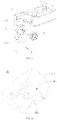
- FIG. 1 is a schematic structural diagram of a bogie according to an embodiment of this application
- FIG. 2 is an enlarged view of area A in FIG. 1
- FIG. 3 is an exploded view of an assembly of a frame and a primary suspension device according to the embodiment of this application.
- the bogie according to this embodiment includes: a frame, wheel sets, a traction device, braking devices and other components, and each component is implemented according to the prior art.
- the frame includes two parallel side beams 1 extending in the longitudinal direction, a cross beam is connected between the two side beams 1, and components such as the traction device and the braking devices can be assembled on the beam.
- the wheel set includes: an axle, wheels symmetrically arranged on the axle and an axle box 2.
- a primary suspension device 3 is arranged between the side beam 1 and the axle box 2 to achieve positioning and buffering between the side beam 1 and the axle box 2.
- a primary buffer device 3 includes: buffer blocks 31 and an annular hoop 32.
- the annular hoop 32 is of a circular ring structure and has a top connected to a bottom surface of an end portion of the side beam 1, and a centerline of the annular hoop 32 extends in a lateral direction.
- a middle part of the axle box 2 is located in a space defined by the annular hoop 32, and a centerline of the axle box 2 coincides with the centerline of the annular hoop 32.
- a plurality of buffer blocks 31 are provided and uniformly arranged between the annular hoop 32 and the axle box 2 to position the side beam 1 and the axle box 2, and forces from lateral, longitudinal and perpendicular directions can be buffered through the buffer blocks 31.
- the implementation of this embodiment in which the buffer blocks are uniformly arranged at a periphery of the axle box can reduce a space required between the axle box and the frame and thus can reduce the height of the frame.
- the annular hoop having a centerline extending in the lateral direction is configured to be connected to the bottom surface of the end portion of the side beam; the axle box is located in the space defined by the annular hoop, and the centerline of the axle box coincides with the centerline of the annular hoop; and the plurality of buffer blocks are uniformly arranged between the annular hoop and the axle box.
- the side beam and the axle box can be positioned and forces in multiple directions such as lateral force, longitudinal force and vertical force can be buffered, thus ensuring even stress.
- a height difference between the side beam and the axle box is only a sum of a thickness of the annular hoop and a height of one buffer block.
- the above-mentioned primary suspension device is relatively simple in structure, can be disassembled and assembled conveniently, and its maintenance process is relatively simple.
- the following describes the positioning method for the components in the primary suspension device.
- a first lateral positioning structure is arranged on an inner side of the buffer block 31, and a second lateral positioning structure is arranged on an outer peripheral surface of the axle box 2.
- the first lateral positioning structure and the second lateral positioning structure cooperate with each other to laterally position the buffer block, thereby avoiding lateral movement of the buffer block.
- the first lateral positioning structure and the second lateral positioning structure may be configured as structures capable of mutually restricting lateral movement.
- the first lateral positioning structure and the second lateral positioning structure are configured as a positioning protrusion and a positioning groove that cooperate with each other.
- the first lateral positioning structure may specifically be configured as a buffer block positioning groove formed in the inner side of the buffer block 31 and extending in the longitudinal direction.
- the second lateral positioning structure may specifically be configured as an axle box positioning protrusion protruding from the outer peripheral surface of the axle box and extending in the longitudinal direction.
- the axle box positioning protrusion can be accommodated in the buffer block positioning groove to limit the lateral movement of the buffer block 31.
- a first longitudinal positioning structure is arranged on the inner side of the buffer block 31, and a second longitudinal positioning structure is arranged on the outer peripheral surface of the axle box 2.
- the first longitudinal positioning structure and the second longitudinal positioning structure cooperate with each other to longitudinally position the buffer block, thereby avoiding longitudinal movement of the buffer block.
- the first longitudinal positioning structure and the second longitudinal positioning structure may be configured as structures capable of mutually restricting longitudinal movement.
- the first longitudinal positioning structure and the second longitudinal positioning structure are configured as a positioning column and a positioning hole that cooperate with each other or configured as a positioning protrusion and a positioning groove that cooperate with each other.
- the first longitudinal positioning structure is specifically configured as a buffer block positioning column arranged on the inner side of the buffer block 31 and having a length direction extending along a radial direction of the annular hoop 32.
- the second longitudinal positioning structure is configured as an axle box positioning hole formed in the outer peripheral surface of the axle box 2.
- the buffer block positioning column can be inserted into the axle box positioning hole to limit the longitudinal movement of the buffer block 31.
- a third lateral positioning structure is arranged on an outer side of the buffer block 31, a fourth lateral positioning structure is arranged on an inner side of the annular hoop 32, and the third lateral positioning structure and the fourth lateral positioning structure cooperate with each other to laterally position the buffer block 31.
- the third lateral positioning structure and the fourth lateral positioning structure may be configured as structures capable of mutually restricting lateral movement.
- the third lateral positioning structure and the fourth lateral positioning structure are configured as a positioning protrusion and a positioning groove that cooperate with each other.
- the third lateral positioning structure is configured as a buffer block positioning protrusion arranged on the outer side of the buffer block 31 and extending in the longitudinal direction.
- the fourth lateral positioning structure is configured as an annular hoop positioning groove formed in the inner side of the annular hoop 32.
- the butter block positioning protrusion can be accommodated in the annular hoop positioning groove to limit the lateral movement of the buffer block 31.
- This embodiment provides a specific implementation of a primary suspension device as follows.
- FIG. 4 is a schematic structural diagram of a buffer block in the bogie according to the embodiment of this application
- FIG. 5 is a schematic diagram of the buffer block in the bogie according to the embodiment of this application seen from another angle
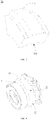
- FIG. 6 is a schematic structural diagram of an axle box in the bogie according to the embodiment of this application
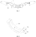
- FIG. 7 is a schematic structural diagram of the frame according to the embodiment of this application
- FIG. 8 is a schematic structural diagram of a lower half loop in the bogie according to the embodiment of this application.
- the buffer block 31 has a fan-shaped longitudinal section. End surfaces of the six buffer blocks 31 are connected end to end to form a closed ring.
- Each buffer block 31 has an inner surface facing the axle box 2 and an outer surface facing the annular hoop 32, and the inner surface and the outer surface are both arc surfaces.
- the inner surface of the buffer block 31 is provided with a buffer block positioning groove 311 extending in the longitudinal direction.
- the outer peripheral surface of the axle box 2 is provided with an annular axle box positioning protrusion 21.
- the axle box positioning protrusion 21 can be accommodated in the buffer block positioning groove 311. An interaction force between a side wall of the axle box positioning protrusion 21 and a side wall of the buffer block positioning groove 311 can limit the lateral movement of the buffer block 31.
- the inner surface of the buffer block 31 (specifically, a bottom surface of the buffer block positioning groove 311) is provided with a buffer block positioning column 312.
- the buffer block positioning column 312 protrudes from the bottom surface of the buffer block positioning groove 311 and extends along the radial direction of the annular hoop 32.
- the outer peripheral surface of the axle box 2 (specifically, a top surface of the axle box positioning protrusion 21) is provided with an axle box positioning hole 22, and the buffer block positioning groove 311 can be inserted into the axle box positioning hole 22.
- the cooperation of the axle box positioning hole 22 and the buffer block positioning groove 311 limits the longitudinal movement and lateral movement of the buffer block 31.
- One buffer block 31 is provided with one buffer block positioning column 312, and the position and number of the axle box positioning holes 22 are set according to the number and position of the buffer block positioning columns 3 12.
- the outer side of the buffer block 31 is provided with a buffer block positioning protrusion 313 extending in the longitudinal direction.
- an annular hoop positioning groove 323 is formed in the inner side of the annular hoop 32 and the buffer block positioning protrusion 313 can be accommodated in the annular hoop positioning groove 323.
- An acting force between side walls of the annular hoop positioning groove 323 and the buffer block positioning protrusion 313 can limit the lateral movement of the buffer block 31.
- the axle box 2, the buffer block 31 and the annular hoop 32 of the above-mentioned structures can cooperate to laterally, longitudinally and perpendicularly position the buffer blocks 31.
- the buffer blocks 31 also can buffer the lateral, longitudinal and perpendicular forces between the side beam 1 and the axle box 2.
- the manner of cooperating and positioning among the axle box 2, the buffer block 31 and the annular hoop 32 is not limited to the above manner, and other manners may also be used, which will not limited in this embodiment.
- the number of buffer blocks 31 is also not limited to six, and may be four, eight or another number.
- this embodiment also provides a specific implementation as follows.
- the annular hoop 32 includes two parts: an upper half hoop 321 and a lower half hoop 322.
- the upper half hoop 321 is fixed on the bottom surface of the side beam 1 with its opening facing downward.
- the lower half hoop 322 is connected to the upper half hoop 321 with its opening facing upward, and forms a circular space together with the upper half hoop 321.
- two ends of the upper half hoop 321 respectively extend outwardly to form half hoop connecting parts 324, and connecting holes 325 are formed in the half hoop connecting parts 324.
- Two ends of the lower half hoop 322 respectively extend outwardly to form half hoop connecting parts 324, and connecting holes 325 are also formed in the half hoop connecting parts 324.
- the upper half hoop 321 is first connected with the side beam 1; then, the half hoop connecting parts 324 in the lower half hoop 322 are aligned with the half hoop connecting parts 324 in the upper half hoop 321, with the connecting holes 325 coinciding; and a bolt 4 passes through the two corresponding connecting holes 325 in sequence from the bottom and is then fitted with a nut for fixing.
- An inner surface of the upper half hoop 321 and an inner surface of the lower half hoop 322 are each provided with the annular hoop positioning groove 323 for accommodating the buffer block positioning protrusions 313.
- the above-mentioned primary suspension device 3 can be used as an independent product applied in various bogies.
- the bogie to which the primary suspension device 3 is applied can be modified adaptively according to the primary suspension device 3.
- This embodiment further provides a rail vehicle including the bogie according to any of the above.
- the annular hoop having a centerline extending in the lateral direction is configured to be connected to the bottom surface of the end portion of the side beam; the axle box is located in the space defined by the annular hoop, and the centerline of the axle box coincides with the centerline of the annular hoop; and the plurality of buffer blocks are uniformly arranged between the annular hoop and the axle box.
- the side beam and the axle box can be positioned and forces in multiple directions such as lateral force, longitudinal force and vertical force can be buffered.
- a height difference between the side beam and the axle box is only a sum of a thickness of the annular hoop and a height of one buffer block.
- the height of the frame can be reduced and the center of gravity of the carriage can be further lowered, which is conducive to improving driving stability.
- the above-mentioned primary suspension device is relatively simple in structure, can be disassembled and assembled conveniently, and its maintenance process is relatively simple.
- orientations or positional relationships are based on the orientations or positional relationships shown in the drawings and are only for the purpose of facilitating and simplifying the description of this application, rather than indicating or implying that the described device or element must have a particular orientation or must be constructed and operated in a particular orientation, and therefore they cannot be construed as limiting this application.
- first and second are used for descriptive purposes only and are not to be construed as indicating or implying a relative importance or implicitly indicating the number of technical features indicated.
- features defined by the term “first” or “second” may include one or more such features, either explicitly or implicitly.
- the meaning of "a plurality of' is at least two, such as two, three, etc., unless specifically defined otherwise.
- connection may be a fixed connection, a detachable connection, or an integrated connection; may be a mechanical connection, an electrical connection or intercommunication; and may be a direct connection, an indirect connection through an intermediate medium, or a communication inside two components or interaction between two components.
- install "link", “connect”, and “fix”
- link may be a fixed connection, a detachable connection, or an integrated connection; may be a mechanical connection, an electrical connection or intercommunication; and may be a direct connection, an indirect connection through an intermediate medium, or a communication inside two components or interaction between two components.
Landscapes
- Engineering & Computer Science (AREA)
- Mechanical Engineering (AREA)
- Vehicle Body Suspensions (AREA)
Applications Claiming Priority (2)
| Application Number | Priority Date | Filing Date | Title |
|---|---|---|---|
| CN201910762791.4A CN112389485B (zh) | 2019-08-19 | 2019-08-19 | 一系悬挂装置、转向架及轨道车辆 |
| PCT/CN2019/117332 WO2021031398A1 (fr) | 2019-08-19 | 2019-11-12 | Dispositif de suspension primaire, bogie et véhicule ferroviaire |
Publications (3)
| Publication Number | Publication Date |
|---|---|
| EP4008600A1 true EP4008600A1 (fr) | 2022-06-08 |
| EP4008600A4 EP4008600A4 (fr) | 2022-09-21 |
| EP4008600B1 EP4008600B1 (fr) | 2024-02-28 |
Family
ID=74603277
Family Applications (1)
| Application Number | Title | Priority Date | Filing Date |
|---|---|---|---|
| EP19942312.0A Active EP4008600B1 (fr) | 2019-08-19 | 2019-11-12 | Dispositif de suspension primaire, bogie et véhicule ferroviaire |
Country Status (4)
| Country | Link |
|---|---|
| EP (1) | EP4008600B1 (fr) |
| CN (1) | CN112389485B (fr) |
| PT (1) | PT4008600T (fr) |
| WO (1) | WO2021031398A1 (fr) |
Families Citing this family (2)
| Publication number | Priority date | Publication date | Assignee | Title |
|---|---|---|---|---|
| CN114228768B (zh) * | 2022-01-04 | 2024-02-27 | 西南交通大学 | 一种轨道车辆内轴箱转向架 |
| CN114670884B (zh) * | 2022-03-24 | 2023-11-17 | 中车青岛四方机车车辆股份有限公司 | 一种径向转向架及轨道车辆 |
Family Cites Families (8)
| Publication number | Priority date | Publication date | Assignee | Title |
|---|---|---|---|---|
| GB813237A (en) * | 1957-08-29 | 1959-05-13 | E C Lenning Proprietary Ltd | Means for resiliently mounting an axle box or the like on a vehicle chassis |
| GB822358A (en) * | 1955-07-26 | 1959-10-21 | Robert Hudson & Sons Proprieta | Improvements in or relating to the suspension of vehicle axles |
| US4438703A (en) * | 1982-02-12 | 1984-03-27 | The Budd Company | Primary suspension system for a railway car |
| CN201276119Y (zh) * | 2008-10-17 | 2009-07-22 | 齐齐哈尔轨道交通装备有限责任公司 | 一种转向架的轴箱弹性悬挂系统 |
| CN202016475U (zh) * | 2011-04-21 | 2011-10-26 | 湘电重型装备股份有限公司 | 一种v形弹簧减震限位装置 |
| CN202847716U (zh) * | 2012-10-31 | 2013-04-03 | 南车株洲电力机车有限公司 | 一种转向架及其轴箱定位装置 |
| EP3416866B1 (fr) * | 2016-02-15 | 2020-04-29 | Bombardier Transportation GmbH | Ensemble guide d'essieu de roue avec des convertisseurs hydromécaniques longitudinaux et train de roulement associé |
| CN207875663U (zh) * | 2018-02-07 | 2018-09-18 | 中车株洲电力机车有限公司 | 一种转向架轮重调节装置 |
-
2019
- 2019-08-19 CN CN201910762791.4A patent/CN112389485B/zh active Active
- 2019-11-12 EP EP19942312.0A patent/EP4008600B1/fr active Active
- 2019-11-12 WO PCT/CN2019/117332 patent/WO2021031398A1/fr not_active Ceased
- 2019-11-12 PT PT199423120T patent/PT4008600T/pt unknown
Also Published As
| Publication number | Publication date |
|---|---|
| WO2021031398A1 (fr) | 2021-02-25 |
| CN112389485B (zh) | 2022-03-18 |
| EP4008600B1 (fr) | 2024-02-28 |
| CN112389485A (zh) | 2021-02-23 |
| PT4008600T (pt) | 2024-03-15 |
| EP4008600A4 (fr) | 2022-09-21 |
Similar Documents
| Publication | Publication Date | Title |
|---|---|---|
| US10011287B2 (en) | Bogie for high-speed railway vehicle | |
| EP4008601A1 (fr) | Bogie et véhicule ferroviaire | |
| US12319322B2 (en) | Bogie framework of rail vehicle and bogie | |
| WO2021022901A1 (fr) | Bogie et véhicule ferroviaire | |
| CN114162164B (zh) | 一种采用铰接转向架的列车 | |
| US20110247520A1 (en) | Freight car bogie and freight car | |
| WO2022032809A1 (fr) | Véhicule ferroviaire | |
| CN112644541B (zh) | 一系悬挂装置、转向架及轨道车辆 | |
| CN114194233B (zh) | 车厢及列车 | |
| EP4008599B1 (fr) | Bogie et véhicule ferroviaire | |
| CN105835898B (zh) | 一种转向架 | |
| WO2020015616A1 (fr) | Bogie de véhicule ferroviaire léger | |
| CN113715862A (zh) | 一种单轮对转向架构架、转向架及轨道车辆 | |
| GB2549547A (en) | High-speed rail vehicle bogie | |
| CN101934740A (zh) | 一种高速磁悬浮车辆用悬浮架装置 | |
| EP4008600B1 (fr) | Dispositif de suspension primaire, bogie et véhicule ferroviaire | |
| EP4063227B1 (fr) | Dispositif radial d'essieu monté de bogie de wagon de marchandises de chemin de fer à montage inférieur | |
| WO2022120933A1 (fr) | Balancier de bogie, bogie et véhicule ferroviaire | |
| WO2020248490A1 (fr) | Boggie | |
| WO2022032808A1 (fr) | Bogie | |
| CN112644542B (zh) | 一种转向架 | |
| CN221340603U (zh) | 一种构架及转向架 | |
| CN109109894B (zh) | 一种非动力工艺转向架 | |
| US2620743A (en) | Railroad car truck | |
| CN105835899B (zh) | 一种牵引拉杆安装接口装置及转向架 |
Legal Events
| Date | Code | Title | Description |
|---|---|---|---|
| STAA | Information on the status of an ep patent application or granted ep patent |
Free format text: STATUS: THE INTERNATIONAL PUBLICATION HAS BEEN MADE |
|
| PUAI | Public reference made under article 153(3) epc to a published international application that has entered the european phase |
Free format text: ORIGINAL CODE: 0009012 |
|
| STAA | Information on the status of an ep patent application or granted ep patent |
Free format text: STATUS: REQUEST FOR EXAMINATION WAS MADE |
|
| 17P | Request for examination filed |
Effective date: 20220301 |
|
| AK | Designated contracting states |
Kind code of ref document: A1 Designated state(s): AL AT BE BG CH CY CZ DE DK EE ES FI FR GB GR HR HU IE IS IT LI LT LU LV MC MK MT NL NO PL PT RO RS SE SI SK SM TR |
|
| STAA | Information on the status of an ep patent application or granted ep patent |
Free format text: STATUS: EXAMINATION IS IN PROGRESS |
|
| A4 | Supplementary search report drawn up and despatched |
Effective date: 20220819 |
|
| RIC1 | Information provided on ipc code assigned before grant |
Ipc: B61F 5/30 20060101AFI20220815BHEP |
|
| 17Q | First examination report despatched |
Effective date: 20220831 |
|
| RIN1 | Information on inventor provided before grant (corrected) |
Inventor name: HAO, TAOGUANG Inventor name: ZHANG, JIE Inventor name: ZHANG, LIJUN Inventor name: BI, YUEKUAN Inventor name: ZHENG, JIANKE Inventor name: SUN, XIUYU Inventor name: ZHANG, LIXIN |
|
| DAV | Request for validation of the european patent (deleted) | ||
| DAX | Request for extension of the european patent (deleted) | ||
| GRAP | Despatch of communication of intention to grant a patent |
Free format text: ORIGINAL CODE: EPIDOSNIGR1 |
|
| STAA | Information on the status of an ep patent application or granted ep patent |
Free format text: STATUS: GRANT OF PATENT IS INTENDED |
|
| INTG | Intention to grant announced |
Effective date: 20231109 |
|
| GRAS | Grant fee paid |
Free format text: ORIGINAL CODE: EPIDOSNIGR3 |
|
| GRAA | (expected) grant |
Free format text: ORIGINAL CODE: 0009210 |
|
| STAA | Information on the status of an ep patent application or granted ep patent |
Free format text: STATUS: THE PATENT HAS BEEN GRANTED |
|
| P01 | Opt-out of the competence of the unified patent court (upc) registered |
Effective date: 20240111 |
|
| AK | Designated contracting states |
Kind code of ref document: B1 Designated state(s): AL AT BE BG CH CY CZ DE DK EE ES FI FR GB GR HR HU IE IS IT LI LT LU LV MC MK MT NL NO PL PT RO RS SE SI SK SM TR |
|
| REG | Reference to a national code |
Ref country code: GB Ref legal event code: FG4D |
|
| REG | Reference to a national code |
Ref country code: CH Ref legal event code: EP |
|
| REG | Reference to a national code |
Ref country code: PT Ref legal event code: SC4A Ref document number: 4008600 Country of ref document: PT Date of ref document: 20240315 Kind code of ref document: T Free format text: AVAILABILITY OF NATIONAL TRANSLATION Effective date: 20240311 |
|
| REG | Reference to a national code |
Ref country code: DE Ref legal event code: R096 Ref document number: 602019047589 Country of ref document: DE |
|
| REG | Reference to a national code |
Ref country code: IE Ref legal event code: FG4D |
|
| REG | Reference to a national code |
Ref country code: LT Ref legal event code: MG9D |
|
| PG25 | Lapsed in a contracting state [announced via postgrant information from national office to epo] |
Ref country code: IS Free format text: LAPSE BECAUSE OF FAILURE TO SUBMIT A TRANSLATION OF THE DESCRIPTION OR TO PAY THE FEE WITHIN THE PRESCRIBED TIME-LIMIT Effective date: 20240628 |
|
| REG | Reference to a national code |
Ref country code: NL Ref legal event code: MP Effective date: 20240228 |
|
| PG25 | Lapsed in a contracting state [announced via postgrant information from national office to epo] |
Ref country code: LT Free format text: LAPSE BECAUSE OF FAILURE TO SUBMIT A TRANSLATION OF THE DESCRIPTION OR TO PAY THE FEE WITHIN THE PRESCRIBED TIME-LIMIT Effective date: 20240228 |
|
| PG25 | Lapsed in a contracting state [announced via postgrant information from national office to epo] |
Ref country code: GR Free format text: LAPSE BECAUSE OF FAILURE TO SUBMIT A TRANSLATION OF THE DESCRIPTION OR TO PAY THE FEE WITHIN THE PRESCRIBED TIME-LIMIT Effective date: 20240529 |
|
| PG25 | Lapsed in a contracting state [announced via postgrant information from national office to epo] |
Ref country code: HR Free format text: LAPSE BECAUSE OF FAILURE TO SUBMIT A TRANSLATION OF THE DESCRIPTION OR TO PAY THE FEE WITHIN THE PRESCRIBED TIME-LIMIT Effective date: 20240228 Ref country code: NL Free format text: LAPSE BECAUSE OF FAILURE TO SUBMIT A TRANSLATION OF THE DESCRIPTION OR TO PAY THE FEE WITHIN THE PRESCRIBED TIME-LIMIT Effective date: 20240228 Ref country code: RS Free format text: LAPSE BECAUSE OF FAILURE TO SUBMIT A TRANSLATION OF THE DESCRIPTION OR TO PAY THE FEE WITHIN THE PRESCRIBED TIME-LIMIT Effective date: 20240528 |
|
| PG25 | Lapsed in a contracting state [announced via postgrant information from national office to epo] |
Ref country code: ES Free format text: LAPSE BECAUSE OF FAILURE TO SUBMIT A TRANSLATION OF THE DESCRIPTION OR TO PAY THE FEE WITHIN THE PRESCRIBED TIME-LIMIT Effective date: 20240228 |
|
| PG25 | Lapsed in a contracting state [announced via postgrant information from national office to epo] |
Ref country code: RS Free format text: LAPSE BECAUSE OF FAILURE TO SUBMIT A TRANSLATION OF THE DESCRIPTION OR TO PAY THE FEE WITHIN THE PRESCRIBED TIME-LIMIT Effective date: 20240528 Ref country code: NO Free format text: LAPSE BECAUSE OF FAILURE TO SUBMIT A TRANSLATION OF THE DESCRIPTION OR TO PAY THE FEE WITHIN THE PRESCRIBED TIME-LIMIT Effective date: 20240528 Ref country code: NL Free format text: LAPSE BECAUSE OF FAILURE TO SUBMIT A TRANSLATION OF THE DESCRIPTION OR TO PAY THE FEE WITHIN THE PRESCRIBED TIME-LIMIT Effective date: 20240228 Ref country code: LT Free format text: LAPSE BECAUSE OF FAILURE TO SUBMIT A TRANSLATION OF THE DESCRIPTION OR TO PAY THE FEE WITHIN THE PRESCRIBED TIME-LIMIT Effective date: 20240228 Ref country code: IS Free format text: LAPSE BECAUSE OF FAILURE TO SUBMIT A TRANSLATION OF THE DESCRIPTION OR TO PAY THE FEE WITHIN THE PRESCRIBED TIME-LIMIT Effective date: 20240628 Ref country code: HR Free format text: LAPSE BECAUSE OF FAILURE TO SUBMIT A TRANSLATION OF THE DESCRIPTION OR TO PAY THE FEE WITHIN THE PRESCRIBED TIME-LIMIT Effective date: 20240228 Ref country code: GR Free format text: LAPSE BECAUSE OF FAILURE TO SUBMIT A TRANSLATION OF THE DESCRIPTION OR TO PAY THE FEE WITHIN THE PRESCRIBED TIME-LIMIT Effective date: 20240529 Ref country code: FI Free format text: LAPSE BECAUSE OF FAILURE TO SUBMIT A TRANSLATION OF THE DESCRIPTION OR TO PAY THE FEE WITHIN THE PRESCRIBED TIME-LIMIT Effective date: 20240228 Ref country code: ES Free format text: LAPSE BECAUSE OF FAILURE TO SUBMIT A TRANSLATION OF THE DESCRIPTION OR TO PAY THE FEE WITHIN THE PRESCRIBED TIME-LIMIT Effective date: 20240228 Ref country code: BG Free format text: LAPSE BECAUSE OF FAILURE TO SUBMIT A TRANSLATION OF THE DESCRIPTION OR TO PAY THE FEE WITHIN THE PRESCRIBED TIME-LIMIT Effective date: 20240228 |
|
| PG25 | Lapsed in a contracting state [announced via postgrant information from national office to epo] |
Ref country code: PL Free format text: LAPSE BECAUSE OF FAILURE TO SUBMIT A TRANSLATION OF THE DESCRIPTION OR TO PAY THE FEE WITHIN THE PRESCRIBED TIME-LIMIT Effective date: 20240228 |
|
| REG | Reference to a national code |
Ref country code: AT Ref legal event code: MK05 Ref document number: 1660989 Country of ref document: AT Kind code of ref document: T Effective date: 20240228 |
|
| PG25 | Lapsed in a contracting state [announced via postgrant information from national office to epo] |
Ref country code: SE Free format text: LAPSE BECAUSE OF FAILURE TO SUBMIT A TRANSLATION OF THE DESCRIPTION OR TO PAY THE FEE WITHIN THE PRESCRIBED TIME-LIMIT Effective date: 20240228 Ref country code: PL Free format text: LAPSE BECAUSE OF FAILURE TO SUBMIT A TRANSLATION OF THE DESCRIPTION OR TO PAY THE FEE WITHIN THE PRESCRIBED TIME-LIMIT Effective date: 20240228 Ref country code: LV Free format text: LAPSE BECAUSE OF FAILURE TO SUBMIT A TRANSLATION OF THE DESCRIPTION OR TO PAY THE FEE WITHIN THE PRESCRIBED TIME-LIMIT Effective date: 20240228 |
|
| PG25 | Lapsed in a contracting state [announced via postgrant information from national office to epo] |
Ref country code: DK Free format text: LAPSE BECAUSE OF FAILURE TO SUBMIT A TRANSLATION OF THE DESCRIPTION OR TO PAY THE FEE WITHIN THE PRESCRIBED TIME-LIMIT Effective date: 20240228 |
|
| PG25 | Lapsed in a contracting state [announced via postgrant information from national office to epo] |
Ref country code: SM Free format text: LAPSE BECAUSE OF FAILURE TO SUBMIT A TRANSLATION OF THE DESCRIPTION OR TO PAY THE FEE WITHIN THE PRESCRIBED TIME-LIMIT Effective date: 20240228 |
|
| PG25 | Lapsed in a contracting state [announced via postgrant information from national office to epo] |
Ref country code: CZ Free format text: LAPSE BECAUSE OF FAILURE TO SUBMIT A TRANSLATION OF THE DESCRIPTION OR TO PAY THE FEE WITHIN THE PRESCRIBED TIME-LIMIT Effective date: 20240228 Ref country code: EE Free format text: LAPSE BECAUSE OF FAILURE TO SUBMIT A TRANSLATION OF THE DESCRIPTION OR TO PAY THE FEE WITHIN THE PRESCRIBED TIME-LIMIT Effective date: 20240228 |
|
| PG25 | Lapsed in a contracting state [announced via postgrant information from national office to epo] |
Ref country code: AT Free format text: LAPSE BECAUSE OF FAILURE TO SUBMIT A TRANSLATION OF THE DESCRIPTION OR TO PAY THE FEE WITHIN THE PRESCRIBED TIME-LIMIT Effective date: 20240228 |
|
| PG25 | Lapsed in a contracting state [announced via postgrant information from national office to epo] |
Ref country code: SK Free format text: LAPSE BECAUSE OF FAILURE TO SUBMIT A TRANSLATION OF THE DESCRIPTION OR TO PAY THE FEE WITHIN THE PRESCRIBED TIME-LIMIT Effective date: 20240228 |
|
| PG25 | Lapsed in a contracting state [announced via postgrant information from national office to epo] |
Ref country code: SM Free format text: LAPSE BECAUSE OF FAILURE TO SUBMIT A TRANSLATION OF THE DESCRIPTION OR TO PAY THE FEE WITHIN THE PRESCRIBED TIME-LIMIT Effective date: 20240228 Ref country code: SK Free format text: LAPSE BECAUSE OF FAILURE TO SUBMIT A TRANSLATION OF THE DESCRIPTION OR TO PAY THE FEE WITHIN THE PRESCRIBED TIME-LIMIT Effective date: 20240228 Ref country code: RO Free format text: LAPSE BECAUSE OF FAILURE TO SUBMIT A TRANSLATION OF THE DESCRIPTION OR TO PAY THE FEE WITHIN THE PRESCRIBED TIME-LIMIT Effective date: 20240228 Ref country code: EE Free format text: LAPSE BECAUSE OF FAILURE TO SUBMIT A TRANSLATION OF THE DESCRIPTION OR TO PAY THE FEE WITHIN THE PRESCRIBED TIME-LIMIT Effective date: 20240228 Ref country code: DK Free format text: LAPSE BECAUSE OF FAILURE TO SUBMIT A TRANSLATION OF THE DESCRIPTION OR TO PAY THE FEE WITHIN THE PRESCRIBED TIME-LIMIT Effective date: 20240228 Ref country code: CZ Free format text: LAPSE BECAUSE OF FAILURE TO SUBMIT A TRANSLATION OF THE DESCRIPTION OR TO PAY THE FEE WITHIN THE PRESCRIBED TIME-LIMIT Effective date: 20240228 Ref country code: AT Free format text: LAPSE BECAUSE OF FAILURE TO SUBMIT A TRANSLATION OF THE DESCRIPTION OR TO PAY THE FEE WITHIN THE PRESCRIBED TIME-LIMIT Effective date: 20240228 |
|
| REG | Reference to a national code |
Ref country code: DE Ref legal event code: R097 Ref document number: 602019047589 Country of ref document: DE |
|
| PLBE | No opposition filed within time limit |
Free format text: ORIGINAL CODE: 0009261 |
|
| STAA | Information on the status of an ep patent application or granted ep patent |
Free format text: STATUS: NO OPPOSITION FILED WITHIN TIME LIMIT |
|
| 26N | No opposition filed |
Effective date: 20241129 |
|
| PG25 | Lapsed in a contracting state [announced via postgrant information from national office to epo] |
Ref country code: SI Free format text: LAPSE BECAUSE OF FAILURE TO SUBMIT A TRANSLATION OF THE DESCRIPTION OR TO PAY THE FEE WITHIN THE PRESCRIBED TIME-LIMIT Effective date: 20240228 |
|
| REG | Reference to a national code |
Ref country code: CH Ref legal event code: PL |
|
| PG25 | Lapsed in a contracting state [announced via postgrant information from national office to epo] |
Ref country code: MC Free format text: LAPSE BECAUSE OF FAILURE TO SUBMIT A TRANSLATION OF THE DESCRIPTION OR TO PAY THE FEE WITHIN THE PRESCRIBED TIME-LIMIT Effective date: 20240228 |
|
| PG25 | Lapsed in a contracting state [announced via postgrant information from national office to epo] |
Ref country code: LU Free format text: LAPSE BECAUSE OF NON-PAYMENT OF DUE FEES Effective date: 20241112 |
|
| REG | Reference to a national code |
Ref country code: CH Ref legal event code: PL |
|
| GBPC | Gb: european patent ceased through non-payment of renewal fee |
Effective date: 20241112 |
|
| PG25 | Lapsed in a contracting state [announced via postgrant information from national office to epo] |
Ref country code: CH Free format text: LAPSE BECAUSE OF NON-PAYMENT OF DUE FEES Effective date: 20241130 |
|
| REG | Reference to a national code |
Ref country code: BE Ref legal event code: MM Effective date: 20241130 |
|
| PG25 | Lapsed in a contracting state [announced via postgrant information from national office to epo] |
Ref country code: GB Free format text: LAPSE BECAUSE OF NON-PAYMENT OF DUE FEES Effective date: 20241112 Ref country code: BE Free format text: LAPSE BECAUSE OF NON-PAYMENT OF DUE FEES Effective date: 20241130 |
|
| PG25 | Lapsed in a contracting state [announced via postgrant information from national office to epo] |
Ref country code: FR Free format text: LAPSE BECAUSE OF NON-PAYMENT OF DUE FEES Effective date: 20241130 |
|
| PG25 | Lapsed in a contracting state [announced via postgrant information from national office to epo] |
Ref country code: IE Free format text: LAPSE BECAUSE OF NON-PAYMENT OF DUE FEES Effective date: 20241112 |
|
| PGFP | Annual fee paid to national office [announced via postgrant information from national office to epo] |
Ref country code: PT Payment date: 20251017 Year of fee payment: 7 |
|
| PGFP | Annual fee paid to national office [announced via postgrant information from national office to epo] |
Ref country code: DE Payment date: 20251117 Year of fee payment: 7 |
|
| PGFP | Annual fee paid to national office [announced via postgrant information from national office to epo] |
Ref country code: IT Payment date: 20251107 Year of fee payment: 7 |
|
| PG25 | Lapsed in a contracting state [announced via postgrant information from national office to epo] |
Ref country code: HU Free format text: LAPSE BECAUSE OF FAILURE TO SUBMIT A TRANSLATION OF THE DESCRIPTION OR TO PAY THE FEE WITHIN THE PRESCRIBED TIME-LIMIT; INVALID AB INITIO Effective date: 20191112 |
|
| PG25 | Lapsed in a contracting state [announced via postgrant information from national office to epo] |
Ref country code: CY Free format text: LAPSE BECAUSE OF FAILURE TO SUBMIT A TRANSLATION OF THE DESCRIPTION OR TO PAY THE FEE WITHIN THE PRESCRIBED TIME-LIMIT; INVALID AB INITIO Effective date: 20191112 |