EP4008606B1 - Stromversorgungssystem - Google Patents
Stromversorgungssystem Download PDFInfo
- Publication number
- EP4008606B1 EP4008606B1 EP21211628.9A EP21211628A EP4008606B1 EP 4008606 B1 EP4008606 B1 EP 4008606B1 EP 21211628 A EP21211628 A EP 21211628A EP 4008606 B1 EP4008606 B1 EP 4008606B1
- Authority
- EP
- European Patent Office
- Prior art keywords
- control unit
- power supply
- supply
- auxiliary
- steering
- Prior art date
- Legal status (The legal status is an assumption and is not a legal conclusion. Google has not performed a legal analysis and makes no representation as to the accuracy of the status listed.)
- Active
Links
Images


Classifications
-
- B—PERFORMING OPERATIONS; TRANSPORTING
- B60—VEHICLES IN GENERAL
- B60R—VEHICLES, VEHICLE FITTINGS, OR VEHICLE PARTS, NOT OTHERWISE PROVIDED FOR
- B60R16/00—Electric or fluid circuits specially adapted for vehicles and not otherwise provided for; Arrangement of elements of electric or fluid circuits specially adapted for vehicles and not otherwise provided for
- B60R16/02—Electric or fluid circuits specially adapted for vehicles and not otherwise provided for; Arrangement of elements of electric or fluid circuits specially adapted for vehicles and not otherwise provided for electric constitutive elements
- B60R16/03—Electric or fluid circuits specially adapted for vehicles and not otherwise provided for; Arrangement of elements of electric or fluid circuits specially adapted for vehicles and not otherwise provided for electric constitutive elements for supply of electrical power to vehicle subsystems or for
-
- B—PERFORMING OPERATIONS; TRANSPORTING
- B60—VEHICLES IN GENERAL
- B60R—VEHICLES, VEHICLE FITTINGS, OR VEHICLE PARTS, NOT OTHERWISE PROVIDED FOR
- B60R16/00—Electric or fluid circuits specially adapted for vehicles and not otherwise provided for; Arrangement of elements of electric or fluid circuits specially adapted for vehicles and not otherwise provided for
- B60R16/02—Electric or fluid circuits specially adapted for vehicles and not otherwise provided for; Arrangement of elements of electric or fluid circuits specially adapted for vehicles and not otherwise provided for electric constitutive elements
-
- B—PERFORMING OPERATIONS; TRANSPORTING
- B62—LAND VEHICLES FOR TRAVELLING OTHERWISE THAN ON RAILS
- B62D—MOTOR VEHICLES; TRAILERS
- B62D5/00—Power-assisted or power-driven steering
- B62D5/04—Power-assisted or power-driven steering electrical, e.g. using an electric servo-motor connected to, or forming part of, the steering gear
- B62D5/0403—Power-assisted or power-driven steering electrical, e.g. using an electric servo-motor connected to, or forming part of, the steering gear characterised by constructional features, e.g. common housing for motor and gear box
- B62D5/0406—Power-assisted or power-driven steering electrical, e.g. using an electric servo-motor connected to, or forming part of, the steering gear characterised by constructional features, e.g. common housing for motor and gear box including housing for electronic control unit
-
- B—PERFORMING OPERATIONS; TRANSPORTING
- B62—LAND VEHICLES FOR TRAVELLING OTHERWISE THAN ON RAILS
- B62D—MOTOR VEHICLES; TRAILERS
- B62D5/00—Power-assisted or power-driven steering
- B62D5/04—Power-assisted or power-driven steering electrical, e.g. using an electric servo-motor connected to, or forming part of, the steering gear
- B62D5/0457—Power-assisted or power-driven steering electrical, e.g. using an electric servo-motor connected to, or forming part of, the steering gear characterised by control features of the drive means as such
- B62D5/0481—Power-assisted or power-driven steering electrical, e.g. using an electric servo-motor connected to, or forming part of, the steering gear characterised by control features of the drive means as such monitoring the steering system, e.g. failures
-
- B—PERFORMING OPERATIONS; TRANSPORTING
- B62—LAND VEHICLES FOR TRAVELLING OTHERWISE THAN ON RAILS
- B62D—MOTOR VEHICLES; TRAILERS
- B62D5/00—Power-assisted or power-driven steering
- B62D5/04—Power-assisted or power-driven steering electrical, e.g. using an electric servo-motor connected to, or forming part of, the steering gear
- B62D5/0457—Power-assisted or power-driven steering electrical, e.g. using an electric servo-motor connected to, or forming part of, the steering gear characterised by control features of the drive means as such
- B62D5/0481—Power-assisted or power-driven steering electrical, e.g. using an electric servo-motor connected to, or forming part of, the steering gear characterised by control features of the drive means as such monitoring the steering system, e.g. failures
- B62D5/0484—Power-assisted or power-driven steering electrical, e.g. using an electric servo-motor connected to, or forming part of, the steering gear characterised by control features of the drive means as such monitoring the steering system, e.g. failures for reaction to failures, e.g. limp home
-
- B—PERFORMING OPERATIONS; TRANSPORTING
- B62—LAND VEHICLES FOR TRAVELLING OTHERWISE THAN ON RAILS
- B62D—MOTOR VEHICLES; TRAILERS
- B62D6/00—Arrangements for automatically controlling steering depending on driving conditions sensed and responded to, e.g. control circuits
- B62D6/08—Arrangements for automatically controlling steering depending on driving conditions sensed and responded to, e.g. control circuits responsive only to driver input torque
- B62D6/10—Arrangements for automatically controlling steering depending on driving conditions sensed and responded to, e.g. control circuits responsive only to driver input torque characterised by means for sensing or determining torque
-
- H—ELECTRICITY
- H02—GENERATION; CONVERSION OR DISTRIBUTION OF ELECTRIC POWER
- H02J—ELECTRIC POWER NETWORKS; CIRCUIT ARRANGEMENTS OR SYSTEMS FOR SUPPLYING OR DISTRIBUTING ELECTRIC POWER; SYSTEMS FOR STORING ELECTRIC ENERGY
- H02J9/00—Circuit arrangements for emergency or stand-by power supply, e.g. for emergency lighting
- H02J9/04—Circuit arrangements for emergency or stand-by power supply, e.g. for emergency lighting in which the distribution system is disconnected from the normal source and connected to a standby source
- H02J9/06—Circuit arrangements for emergency or stand-by power supply, e.g. for emergency lighting in which the distribution system is disconnected from the normal source and connected to a standby source with automatic change-over, e.g. UPS systems
- H02J9/068—Electronic means for switching from one power supply to another power supply, e.g. to avoid parallel connection
-
- B—PERFORMING OPERATIONS; TRANSPORTING
- B62—LAND VEHICLES FOR TRAVELLING OTHERWISE THAN ON RAILS
- B62D—MOTOR VEHICLES; TRAILERS
- B62D5/00—Power-assisted or power-driven steering
- B62D5/04—Power-assisted or power-driven steering electrical, e.g. using an electric servo-motor connected to, or forming part of, the steering gear
- B62D5/0457—Power-assisted or power-driven steering electrical, e.g. using an electric servo-motor connected to, or forming part of, the steering gear characterised by control features of the drive means as such
- B62D5/046—Controlling the motor
Definitions
- the invention relates to a power supply system.
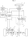
- the steering system 2 is a steer-by-wire steering system.
- the steering system 2 includes a steering control device 1 that controls an operation of the steering system 2.
- the steering system 2 includes a steering unit 4 that is steered by a driver using a steering wheel 3 and a turning unit 6 that turns turning wheels 5 according to steering input to the steering unit 4 by a driver.
- the steering system 2 according to this embodiment has a structure in which a power transmission path between the steering unit 4 and the turning unit 6 is normally mechanically cut off.
- a vehicle speed sensor 44 is connected to the steering control device 1.
- the vehicle speed sensor 44 detects a vehicle speed value V which is set as information indicating a travel speed of a vehicle.
- An external control device 60 is connected to the steering control device 1 via an onboard network 50 such as a CAN.
- the external control device 60 is provided in the vehicle separately from the steering control device 1 and controls an operation of a system that exhibits a desired function which is different from the function exhibited by the steering system 2.
- the steering control device 1 receives information from the external control device 60 via the onboard network 50.
- control circuit 82a is different from the control circuit 72a in that the control circuit 82a is configured not to output information to an auxiliary-power-supply control unit 128 (which will be described later) of the auxiliary power supply device 120 via a signal line 140.
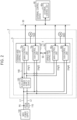
- the auxiliary power supply device 120 includes an auxiliary power supply 121, an electrical circuit 122, switches 123, 124, and 125, diodes 126 and 127, and an auxiliary-power-supply control unit 128.
- a voltage V2 of the auxiliary power supply 121 is set to a value which is higher than a voltage V0 required for causing the motors 13 and 33 or the control units 70 and 80 to operate appropriately and lower than a voltage V1 of the main power supply 100.
- the electrical circuit 122 switches a state of connection to the power supply line L11 such that the auxiliary power supply 121 is charged with or discharges electric power.
- the electrical circuit 122 switches the state of connection to the power supply line L11 such that the auxiliary power supply 121 is disconnected in order not to discharge electric power from the auxiliary power supply 121.
- the switch 123 is provided at a portion of the power supply line L11 in the auxiliary power supply device 120.
- the switch 123 is located on the upstream side of the connection point P13, that is, the switch 123 is located closer to the main power supply 100 than the connection point P13 is.
- the switch 123 connects and disconnects the power supply line L 11.
- the switch 124 is provided at a portion of the power supply line L111 in the auxiliary power supply device 120.
- the switch 124 connects and disconnects the power supply line L111.
- the switch 125 is located at a portion of the power supply line L112 in the auxiliary power supply device 120.
- the switch 125 connects and disconnects the power supply line L112.
- connection point P15 is set in the power supply line L112.
- the connection point P15 in the power supply line L112 and a connection point P16 in the power supply line L21 are connected by a power supply line L113.
- the diode 126 is provided at a portion of the power supply line L113.
- a cathode of the diode 126 is connected to the connection point P16 in the power supply line L21.
- An anode of the diode 126 is connected to the connection point P15 in the power supply line L113.
- Each of the diodes 126 and 127 permits a flow of electric power from the anode to the cathode and restrains a flow of electric power from the cathode to the anode.
- the diodes 126 and 127 constitute an OR circuit that supplies electric power from a power supply with a higher supply voltage out of the main power supply 100 and the auxiliary power supply 121 to the control circuit 72a.
- the diodes 126 and 127 constitute an OR circuit that supplies electric power from one of the main power supply 100 and the auxiliary power supply 121 to the control circuit 72a, the one of the main power supply 100 and the auxiliary power supply 121 having a higher supply voltage than a supply voltage of the other.
- the OR circuit constituted by the diodes 126 and 127 is a so-called wired OR.
- the OR circuit constituted by the diodes 126 and 127 corresponds to a selection circuit that selects electric power from a power supply with a higher supply voltage out of the main power supply 100 and the auxiliary power supply 121 such that the electric power is supplied to the steering-side control unit 70 (the turning-side control unit 80).
- the auxiliary-power-supply control unit 128 includes a central processing unit (CPU) and a memory which are not illustrated and the CPU executes a program stored in the memory at intervals of a predetermined calculation cycle. Accordingly, various processes are performed.
- CPU central processing unit
- memory which are not illustrated and the CPU executes a program stored in the memory at intervals of a predetermined calculation cycle. Accordingly, various processes are performed.
- the auxiliary-power-supply control unit 128 controls switching of the connection state of the electrical circuit 122 and controls switching-on/off of the switches 123, 124, and 125.
- the auxiliary-power-supply control unit 128 monitors a voltage of the main power supply 100.
- the auxiliary-power-supply control unit 128 determines that a source voltage Vb of the main power supply 100 has decreased when the source voltage Vb of the main power supply 100 is lower than a threshold voltage Vth1 as expressed by the following Expression (B).
- the threshold voltage Vth1 serves as a reference for determining a decrease in voltage of the main power supply 100 and is set based on the voltage V0 required for appropriately operating the motors 13 and 33 or the control units 70 and 80. In this embodiment, the threshold voltage Vth1 is set to the same value as the voltage V0.
- the auxiliary-power-supply control unit 128 When a decrease in voltage of the main power supply 100 has not been detected, the auxiliary-power-supply control unit 128 maintains the switches 123 and 124 in a closed state in which the switches 123 and 124 are switched on and maintains the switch 125 in an open state in which the switch 125 is switched off.
- the auxiliary-power-supply control unit 128 switches the switches 123 and 124 from the closed state in which the switches 123 and 124 are switched on to the open state in which the switches 123 and 124 are switched off. Thereafter, the auxiliary-power-supply control unit 128 switches the switch 125 from the open state in which the switch 125 is switched off to the closed state in which the switch 125 is switched on.
- the switches 123 and 124 are switched from the closed state in which the switches 123 and 124 are switched on to the open state in which the switches 123 and 124 are switched off. Thereafter, the switch 125 is switched from the open state in which the switch 125 is switched off to the closed state in which the switch 125 is switched on. Accordingly, electric power from the auxiliary power supply 121 is supplied to the power circuit 71a of the steering-side control unit 70 via the power supply line L112 and a part of the power supply line L11.
- the voltage V2 of the auxiliary power supply 121 is higher than the voltage of the power supply line L11 due to the failure of the main power supply 100. Accordingly, even when supply of electric power from the main power supply 100 to the steering-side control unit 70 is stopped due to a failure of the main power supply 100, the auxiliary power supply 121 backs up the supply of electric power to the power circuit 71a of the steering-side control unit 70.
- a diode instead of the switch 125 may be provided in the power supply line L112.
- the switch 125 instead of a diode is provided in the power supply line L112 for supplying electric power to the power circuit 71a requiring higher electric power.
- a switch instead of the diode 126 may be provided in the power supply line L113.
- the control circuit 72a may be reset due to instantaneous stopping of the supply of electric power to the control circuit 72a.
- the steering-side control unit 70 and the turning-side control unit 80 correspond(s) to a system control unit.
- the diode 127 corresponds to a first diode.
- the diode 126 corresponds to a second diode.
- the power supply line L21 corresponds to a first power supply path.
- the power supply line L113 corresponds to a second power supply path.
- the auxiliary-power-supply control unit 128 corresponds to an auxiliary-power-supply control unit.
- the control circuit 72a has a function of detecting a voltage of electric power supplied via the power supply line L21 as a source voltage Vig1 of the main power supply 100.
- the source voltage Vig1 is a source voltage at the connection point P16 in the power supply line L21.
- the control circuit 72b has a function of detecting a voltage of electric power supplied via the power supply line L22 as a source voltage Vig2 of the main power supply 100.
- the source voltage Vig2 is a source voltage at the connection point P12 in the power supply line L21.
- control circuit 82a of the main control unit 80a of the turning-side control unit 80 having the same configuration as that of the steering-side control unit 70 has a function of detecting a voltage of electric power supplied via a power supply line corresponding to the power supply line L21 as a source voltage Vig3 of the main power supply 100.
- the control circuit 82b of the sub control unit 80b of the turning-side control unit 80 has a function of detecting a voltage of electric power supplied via a power supply line corresponding to the power supply line L22 as a source voltage Vig4 of the main power supply 100.
- the detected source voltages Vig1 to Vig4 are output to the control units 70a and 70b of the steering-side control unit 70 and the control units 80a and 80b of the turning-side control unit 80 via the local network 90 and are shared by the control units 70 and 80.
- the control circuit 72a of the main control unit 70a acquires the source voltages Vig2 and Vig4 which are input via the local network 90.
- the control circuit 72a of the main control unit 70a acquires a vehicle stop flag FLG1 which is input via the onboard network 50 and acquires a turning-side vehicle stop flag FLG1t which is input via the local network 90.
- the vehicle stop flag FLG1 is information which is generated by the external control unit 60a and output to the onboard network 50 and which indicates an operation status of the vehicle. That is, the vehicle stop flag FLG1 is information indicating that the operation of the vehicle is stopped, that is, that the start switch 110 is turned off and the supply of electric power from the main power supply 100 is stopped.
- the external control unit 60a is configured to generate the vehicle stop flag FLG1 as a determination result indicating that the operation of the vehicle is stopped by detecting turning-on/off of the start switch 110 or detecting a vehicle speed value V from the vehicle speed sensor 44.
- the turning-side vehicle stop flag FLG1t is information which is generated based on the vehicle stop flag FLG1 acquired via the onboard network 50 by the control circuit 82a of the main control unit 80a of the turning-side control unit 80 and is information which is acquired from the control circuit 82a via the local network 90 by the control circuit 72a. That is, the control circuit 82a of the turning-side control unit 80 acquires the vehicle stop flag FLG1 which is input via the onboard network 50 similarly to the control circuit 72a.
- the vehicle stop flag FLG1 acquired in this way by the control circuit 82a is output as the turning-side vehicle stop flag FLG1t to the main control unit 70a of the steering-side control unit 70 via the local network 90.
- the control circuit 72a determines that the start switch 110 is turned off and the supply of electric power is stopped as the status of supply of electric power from the main power supply 100. That is, the control circuit 72a determines that all of the source voltage Vig2 detected by the steering-side control unit 70 and the source voltage Vig4 acquired by the turning-side control unit 80 are lower than the threshold voltage Vth2.
- the threshold voltage Vth2 is a value in a range in which it can be determined that the supply of electric power from the main power supply 100 is stopped, the range being experimentally obtained.
- the threshold voltage Vth2 is set based on the value of the source voltage Vig2 when the supply of electric power from the main power supply 100 is stopped or the source voltage Vig4 assumed to indicate substantially the same value as the source voltage Vig2.
- the conditions regarding the source voltages Vig2 and Vig4 are added and the conditions regarding the source voltages Vig1 and Vig3 are not added when it is determined whether the start switch 110 is turned off and the supply of electric power from the main power supply 100 is stopped. This is because the source voltages Vig2 and Vig4 change to decrease to the threshold voltage Vth2 when the start switch 110 is turned off and the source voltages Vig1 and Vig3 may not decrease to the threshold voltage Vth2 when the start switch 110 is turned off.
- the reason why the source voltage Vig1 and Vig3 do not decrease to the threshold voltage Vth2 when the start switch 110 is turned off is that supply of electric power may be maintained similarly to the case in which the start switch 110 is turned on by the functions of the auxiliary power supply 121 and the diodes 126 and 127 even when the start switch 110 is turned off.
- an absolute value of a difference between the source voltage Vig1 and the source voltage Vig2 is information indicating an amount by which the source voltage Vig2 changes to decrease when the start switch 110 is turned off.
- the control circuit 72a When it is determined that the supply of electric power from the main power supply 100 is stopped, the control circuit 72a performs a process associated with the stopping such that the operation of the steering-side control unit 70 stops. In this case, when the operation of the steering-side control unit 70 is stopped, the control circuit 72a performs the process required for stopping the operation of the steering-side control unit 70, generates a stop permission flag FLG2 as information indicating that the operation is stopped for the auxiliary-power-supply control unit 128, and outputs the stop permission flag FLG2 to the auxiliary-power-supply control unit 128 via the signal line 140.
- This slight time difference includes a time period until the stop permission flag FLG2 is input to the auxiliary-power-supply control unit 128 after the stop permission flag FLG2 has been output or a time period until the auxiliary-power-supply control unit 128 actually stops the operation thereof after the stop permission flag FLG2 has been input.
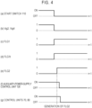
- the statuses of detecting of the source voltages Vig2 and Vig4 indicate the state in which the start switch 110 is turned on. That is, the source voltages Vig2 and Vig4 are in a status in which the source voltages Vig2 and Vig4 are detected to be equal to or greater than the threshold voltage Vth2, the status being indicated by "1" in the drawing.
- the auxiliary-power-supply control unit 128 is in a status in which it operates to perform back-up using the auxiliary power supply 121 when the amount of electric power supplied from the main power supply 100 decreases, the status being indicated by "ON” in the drawing.
- the supply of electric power to the control units 70 and 80 is in a status in which electric power is supplied to the control units 70 and 80 from the main power supply 100 or the auxiliary power supply 121 such that the control units 70 and 80 continue to operate, the status being indicated by "ON" in the drawing.
- the start switch 110 is switched off as illustrated in the portion (a) in FIG. 4 , the supply of electric power from the main power supply 100 to the control units 70 and 80 is stopped.
- the statuses of detecting of the source voltages Vig2 and Vig4 outputting of the vehicle stop flag FLG1, outputting of the turning-side vehicle stop flag FLG1t, outputting of the stop permission flag FLG2, operating of the auxiliary-power-supply control unit 128, and supply of electric power to the control units 70 and 80 in the power supply system S indicate the state in which the start switch 110 is turned off.
- the source voltages Vig2 and Vig4 transition to a status in which the source voltages are detected to be less than the threshold voltage Vth2, the status being indicated by "0 (zero)" in the drawing.
- the vehicle stop flag FLG1 transitions to a status in which it is output from the external control unit 60a, the status being indicated by “1” in the drawing.
- the turning-side vehicle stop flag FLG1t transitions to a status in which it is output from the control circuit 82a of the turning-side control unit 80, the status being indicated by "1" in the drawing.
- the auxiliary-power-supply control unit 128 does not continue to operate and can stop the operation thereof in the situation in which the steering-side control unit 70 stops the operation thereof, and the auxiliary-power-supply control unit 128 does not stop the operation thereof and can continue to operate in the situation in which the steering-side control unit 70 continues to operate.
- the turning-side control unit 80 does not stop the operation thereof and can continue to operate in the situation in which the steering-side control unit 70 continues to operate.
- (1-1) For example, when the configuration for generating and outputting the stop permission flag FLG2 is not provided, there is a likelihood that the auxiliary-power-supply control unit 128 will not able to determine that the control units 70 and 80 are to stop their operations even when the control units 70 and 80 are to stop their operations in a state in which the supply of electric power from the main power supply 100 is stopped.
- the auxiliary-power-supply control unit 128 tries to continuously operate even in the state in which the supply of electric power from the main power supply 100 is stopped, the auxiliary power supply 121 backs up supply of electric power to the control circuits 72a and 82a instead of the main power supply 100.
- control units 70 and 80 are continuously supplied with electric power from the auxiliary power supply 121, the control units 70 and 80 fall into an unexpected situation in which they continue to operate even when their operations are to be stopped in the state in which the supply of electric power from the main power supply 100 is stopped. As in this embodiment, this causes a problem particularly when the function of a diode OR that selects electric power from the power supply with a higher supply voltage out of the main power supply 100 and the auxiliary power supply 121 is provided.
- control units 70 and 80 and the auxiliary-power-supply control unit 128 it is possible to set a rule for the control units 70 and 80 and the auxiliary-power-supply control unit 128 to prevent a situation where the control units 70 and 80 or the auxiliary-power-supply control unit 128 continue(s) to operate when the control units 70 and 80 or the auxiliary-power-supply control unit 128 should stop the operation thereof in the relation with the operation status of the other control unit(s), or the control units 70 and 80 or the auxiliary-power-supply control unit 128 stop(s) the operation thereof when the control units 70 and 80 or the auxiliary-power-supply control unit 128 should not stop the operation thereof in the relation with the operation status of the other control unit (s).
- the control units 70 and 80 and the auxiliary-power-supply control unit 128 fall into an unexpected situation.
- a rule is set such that the control units 70 and 80 stop their operations when the control units 70 and 80 and the auxiliary-power-supply control unit 128 should stop the operations in consideration of the status of supply of electric power from the main power supply 100, that is, the vehicle stop flag FLG1 which is information indicating the operation status of the vehicle.
- This configuration is effective for allowing the control units 70 and 80 to perform appropriate control based on the operation status of the vehicle.
- diagnosis information is generated and stored.
- the diagnosis information is used for identifying a kind of an abnormality or the like detected as the diagnosis result, at the time of later maintenance.
- Examples of the kind of an abnormality detected as the diagnosis result include a communication abnormality in which communication between the steering-side control unit 70 and the auxiliary-power-supply control unit 128 via the signal line 140 is not normally performed.
- Examples of a situation in which the communication abnormality should be detected includes a situation in which the auxiliary-power-supply control unit 128 stops the operation thereof when communication between the steering-side control unit 70 and the auxiliary-power-supply control unit 128 via the signal line 140 is being performed and the steering-side control unit 70 is operating continuously.
- the steering-side control unit 70 and the auxiliary-power-supply control unit 128 stop their operations without determining mutual situations in the state in which supply of electric power from the main power supply 100 is stopped. Accordingly, there is a likelihood that a communication abnormality may be detected as the diagnosis result even when the communication abnormality should not be detected. In this case, an abnormality cannot be correctly identified at the time of later maintenance and a decrease in work efficiency of maintenance work or the like may be caused.
- the specific configuration of the steering-side control unit 70 is the same as a configuration in which the steering-side auxiliary power supply device 120S is replaced with the auxiliary power supply device 120 according to the first embodiment.
- the power supply lines L1 and L2, that is, the main power supply 100 are/is connected to the main control unit 70a of the steering-side control unit 70 via the auxiliary power supply device 120S.
- the power supply lines L1 and L2, that is, the main power supply 100 are/is directly connected to the sub control unit 70b of the steering-side control unit 70 without passing through the auxiliary power supply device 120S.
- the auxiliary power supply device 120S is configured to communicate with the main control unit 70a of the steering-side control unit 70 via a dedicated signal line 140S.
- the control circuit 72a of the steering-side control unit 70 determines that the start switch 110 is turned off and the supply of electric power from the main power supply 100 is stopped, and generates and outputs the stop permission flag FLG2. Accordingly, the auxiliary power supply device 120S stops supply of electric power to the steering-side control unit 70 by stopping the function of backing up supply of electric power from the main power supply 100 using the auxiliary power supply 121.
- the control circuit 82a of the turning-side control unit 80 determines that the start switch 110 is turned off and the supply of electric power from the main power supply 100 is stopped, and generates and outputs the stop permission flag FLG2. Accordingly, the auxiliary power supply device 120T stops supply of electric power to the turning-side control unit 80 by stopping the function of backing up supply of electric power from the main power supply 100 using the auxiliary power supply 121.
Landscapes
- Engineering & Computer Science (AREA)
- Mechanical Engineering (AREA)
- Chemical & Material Sciences (AREA)
- Combustion & Propulsion (AREA)
- Transportation (AREA)
- Business, Economics & Management (AREA)
- Emergency Management (AREA)
- Power Engineering (AREA)
- Power Steering Mechanism (AREA)
- Steering Control In Accordance With Driving Conditions (AREA)
- Charge And Discharge Circuits For Batteries Or The Like (AREA)
- Direct Current Feeding And Distribution (AREA)
Claims (7)
- Ein Energieversorgungssystem, dadurch gekennzeichnet, dass es aufweist:eine Systemsteuereinheit, die konfiguriert ist, um unter Verwendung elektrischer Energie von einer Hauptenergiequelle (100) zu operieren, um eine Operation eines Lenksystems zu steuern, das in einem Fahrzeug montiert ist, das eine gewünschte Funktion ausführt;eine Zusatzenergiequelle (121), die separat zu der Hauptenergiequelle (100) vorgesehen ist und konfiguriert ist, um Unterstützung beim Zuführen der elektrischen Energie zu der Systemsteuereinheit gemäß einem Zuführungsstatus der elektrischen Energie von der Hauptenergiequelle (100) bereitzustellen; undeine Zusatzenergiequellensteuereinheit, die konfiguriert ist, um einen Zuführungsstatus der elektrischen Energie zu der Systemsteuereinheit von der Zusatzenergiequelle (121) derart zu steuern, dass die Unterstützung bereitgestellt wird,wobei die Systemsteuereinheit und die Zusatzenergiequellensteuereinheit derart konfiguriert sind, dass Informationen mindestens einer Steuereinheit der Systemsteuereinheit und der Zusatzenergiequellensteuereinheit an eine andere Steuereinheit der Systemsteuereinheit und der Zusatzenergiequellensteuereinheit ausgegeben werden können, undwobei die mindestens eine Steuereinheit konfiguriert ist, um Informationen, die angeben, dass eine Operation der mindestens einen Steuereinheit gestoppt ist, an die andere Steuereinheit auszugeben, wenn die mindestens eine Steuereinheit die Operation der mindestens einen Steuereinheit stoppt.
- Das Energieversorgungssystem gemäß Anspruch 1, dadurch gekennzeichnet, dass:der Zuführungsstatus der elektrischen Energie von der Hauptenergiequelle (100) und ein Operationsstatus eines Montageziels des Systems miteinander korreliert sind; unddie mindestens eine Steuereinheit konfiguriert ist, um zu bestimmen, ob die Operation der mindestens einen Steuereinheit zu stoppen ist, basierend auf dem Operationsstatus des Montageziels des Systems, und um Informationen, die angeben, dass die Operation der mindestens einen Steuereinheit gestoppt ist, an die andere Steuereinheit auszugeben, wenn die mindestens eine Steuereinheit bestimmt, dass die Operation der mindestens einen Steuereinheit gestoppt ist.
- Das Energieversorgungssystem gemäß Anspruch 1 oder 2, dadurch gekennzeichnet, dass:in einem Fall, in dem eine Steuereinheit der Systemsteuereinheit und der Zusatzenergiequellensteuereinheit eine erste Steuereinheit ist und eine andere Steuereinheit der Systemsteuereinheit und der Zusatzenergiequellensteuereinheit eine zweite Steuereinheit ist,die erste Steuereinheit konfiguriert ist, um Informationen, die einen Operationsstatus eines Montageziels des Systems angeben, von einer externen Steuereinheit zu empfangen, die in dem Montageziel des Systems separat zu der Systemsteuereinheit und der Zusatzenergiequellensteuereinheit vorgesehen ist, so dass der Operationsstatus des Montageziels des Systems bestimmt werden kann;die erste Steuereinheit konfiguriert ist, um Informationen, die angeben, dass die erste Steuereinheit eine Operation der ersten Steuereinheit stoppt, an die zweite Steuereinheit auszugeben, wenn bestimmt wird, dass eine Operation des Montageziels des Systems gestoppt ist, unter einer Bedingung, dass Stoppen der Operation des Montageziels des Systems unter Verwendung der Informationen bestimmt wird, die den Operationsstatus des Montageziels des Systems angeben, wenn die erste Steuereinheit die Operation der ersten Steuereinheit stoppt; unddie zweite Steuereinheit konfiguriert ist, um zu bestimmen, ob eine Operation der zweiten Steuereinheit zu stoppen ist, unter Verwendung der Informationen, die angeben, dass die erste Steuereinheit die Operation der ersten Steuereinheit stoppt, wobei die Informationen von der ersten Steuereinheit eingegeben werden.
- Das Energieversorgungssystem gemäß einem der Ansprüche 1 bis 3, dadurch gekennzeichnet, dass
die Systemsteuereinheit und die Zusatzenergiequellensteuereinheit konfiguriert sind, um einen Operationsstatus eines Montageziels des Systems unter Verwendung einer Quellenspannung als Informationen zu bestimmen, die die Zuführungsstatus der elektrischen Energie von der Hauptenergiequelle (100) angeben. - Das Energieversorgungssystem gemäß einem der Ansprüche 1 bis 4, dadurch gekennzeichnet, dass:die Zusatzenergiequelle (121) die Unterstützung bei der Zufuhr der elektrischen Energie durch Sichern der Zufuhr der elektrischen Energie zur Systemsteuereinheit anstelle der Hauptenergiequelle (100) unter einer Bedingung bereitstellt, dass es eine Abnahme der elektrischen Energie gibt, die von der Hauptenergiequelle (100) zugeführt wird;das Energieversorgungssystem ferner eine Auswahlschaltung aufweist, die zwischen der Hauptenergiequelle (100) und der Zusatzenergiequelle (121) und der Systemsteuereinheit vorgesehen ist, wobei die Auswahlschaltung konfiguriert ist, um die elektrische Energie von einer der Hauptenergiequelle (100) und der Zusatzenergiequelle (121) auszuwählen, so dass die elektrische Energie der Systemsteuereinheit zugeführt wird, wobei die eine der Hauptenergiequelle (100) und der Zusatzenergiequelle (121) eine höhere Versorgungsspannung als eine Versorgungsspannung einer anderen der Hauptenergiequelle (100) und der Zusatzenergiequelle (121) hat; unddie Zusatzenergiequellensteuereinheit konfiguriert ist, um die Zusatzenergiequelle (121) derart zu steuern, dass die elektrische Energie von mindestens der Zusatzenergiequelle (121) der Systemsteuereinheit mittels der Auswahlschaltung zugeführt wird, während die Hauptenergiequelle (100) die elektrische Energie der Systemsteuereinheit zuführt.
- Das Energieversorgungssystem gemäß Anspruch 5, dadurch gekennzeichnet, dass die Auswahlschaltung beinhaltet:eine erste Diode, die in einem ersten Energieversorgungspfad vorgesehen ist, der ein Pfad zum Zuführen der elektrischen Energie von der Hauptenergiequelle (100) zu der Systemsteuereinheit ist; undeine zweite Diode, die mit einem Abschnitt der ersten Diode verbunden ist, die in dem ersten Energieversorgungspfad vorgesehen ist, wobei der Abschnitt der ersten Diode sich auf einer Seite der Systemsteuereinheit befindet und die zweite Diode in einem zweiten Energieversorgungspfad vorgesehen ist, der ein Pfad zum Zuführen der elektrischen Energie von der Zusatzenergiequelle (121) zur Systemsteuereinheit ist.
- Das Energieversorgungssystem gemäß einem der Ansprüche 1 bis 6, dadurch gekennzeichnet, dass:
das Lenksystem zum Operieren mindestens eines eines Lenkrads und eines sich drehenden Rads, die in dem Fahrzeug vorgesehen sind, funktioniert.
Applications Claiming Priority (1)
| Application Number | Priority Date | Filing Date | Title |
|---|---|---|---|
| JP2020200555A JP7637502B2 (ja) | 2020-12-02 | 2020-12-02 | 電源システム |
Publications (3)
| Publication Number | Publication Date |
|---|---|
| EP4008606A2 EP4008606A2 (de) | 2022-06-08 |
| EP4008606A3 EP4008606A3 (de) | 2022-10-12 |
| EP4008606B1 true EP4008606B1 (de) | 2024-07-10 |
Family
ID=78820265
Family Applications (1)
| Application Number | Title | Priority Date | Filing Date |
|---|---|---|---|
| EP21211628.9A Active EP4008606B1 (de) | 2020-12-02 | 2021-12-01 | Stromversorgungssystem |
Country Status (4)
| Country | Link |
|---|---|
| US (1) | US11919579B2 (de) |
| EP (1) | EP4008606B1 (de) |
| JP (1) | JP7637502B2 (de) |
| CN (1) | CN114572126B (de) |
Families Citing this family (3)
| Publication number | Priority date | Publication date | Assignee | Title |
|---|---|---|---|---|
| WO2023046265A1 (en) * | 2021-09-22 | 2023-03-30 | Thyssenkrupp Presta Ag | Method to control a steering system of a motor vehicle with increased maximum output power of actuator motor after unilateral failure of the redundant system |
| JP7839034B2 (ja) | 2022-06-24 | 2026-04-01 | 株式会社ジェイテクト | 電源装置 |
| JP2024060327A (ja) * | 2022-10-19 | 2024-05-02 | 株式会社ジェイテクト | 車両用電源システム及び車両用電源システムの制御方法 |
Family Cites Families (20)
| Publication number | Priority date | Publication date | Assignee | Title |
|---|---|---|---|---|
| JP3915411B2 (ja) * | 2001-02-08 | 2007-05-16 | 株式会社デンソー | 車両用電子制御装置 |
| JP4067901B2 (ja) * | 2002-07-26 | 2008-03-26 | 株式会社ジェイテクト | 車両用操舵制御システム |
| JP4324798B2 (ja) * | 2002-08-01 | 2009-09-02 | 株式会社ジーエス・ユアサコーポレーション | 乗物用電源装置およびこの電源装置を備えた乗物 |
| JP4882417B2 (ja) * | 2006-02-24 | 2012-02-22 | 株式会社ジェイテクト | 電動パワーステアリング装置 |
| JP5055984B2 (ja) * | 2006-12-01 | 2012-10-24 | パナソニック株式会社 | 蓄電装置 |
| JP5130694B2 (ja) * | 2006-11-02 | 2013-01-30 | パナソニック株式会社 | 車両用電源装置に用いる蓄電装置、及び車両用電源装置 |
| JP5135971B2 (ja) * | 2007-09-27 | 2013-02-06 | 株式会社ジェイテクト | 電動パワーステアリング装置のモータ制御装置 |
| KR101438502B1 (ko) * | 2008-09-05 | 2014-10-30 | 현대모비스 주식회사 | Mdps용 ecu 전원 제어 회로 |
| JP5526613B2 (ja) | 2008-10-23 | 2014-06-18 | 日産自動車株式会社 | 車両用電源供給制御装置、及び車両用電源供給制御方法 |
| US9321480B2 (en) * | 2011-06-01 | 2016-04-26 | Toyota Jidosha Kabushiki Kaisha | Vehicle steering control apparatus |
| JP2013071550A (ja) * | 2011-09-27 | 2013-04-22 | Jtekt Corp | 車両操舵装置の制御装置 |
| US9804622B2 (en) * | 2012-01-05 | 2017-10-31 | Schneider Electric It Corporation | Calibration of current sensors in parallel power converters |
| CN107546790A (zh) * | 2016-06-29 | 2018-01-05 | 深圳市华思旭科技有限公司 | 供电组件和方法 |
| US10168364B2 (en) * | 2016-11-29 | 2019-01-01 | Wipro Limited | Battery monitoring system for a vehicle and a method thereof |
| JP2018117437A (ja) * | 2017-01-17 | 2018-07-26 | 株式会社ジェイテクト | 補助電源装置および電源システム |
| DE102017104977A1 (de) * | 2017-03-09 | 2018-09-13 | Dr. Ing. H.C. F. Porsche Aktiengesellschaft | Bordnetzanordnung für ein Kraftfahrzeug |
| JP6686963B2 (ja) * | 2017-04-27 | 2020-04-22 | 株式会社デンソー | 回転電機制御装置及び制御システム |
| JP7082755B2 (ja) | 2018-02-15 | 2022-06-09 | 株式会社ジェイテクト | 電源装置 |
| JP7120075B2 (ja) * | 2019-02-26 | 2022-08-17 | トヨタ自動車株式会社 | 車両の制御装置 |
| JP2020142733A (ja) * | 2019-03-08 | 2020-09-10 | 株式会社ジェイテクト | 補助電源装置及びステアリング装置 |
-
2020
- 2020-12-02 JP JP2020200555A patent/JP7637502B2/ja active Active
-
2021
- 2021-11-29 CN CN202111435248.7A patent/CN114572126B/zh active Active
- 2021-12-01 EP EP21211628.9A patent/EP4008606B1/de active Active
- 2021-12-01 US US17/540,000 patent/US11919579B2/en active Active
Also Published As
| Publication number | Publication date |
|---|---|
| US11919579B2 (en) | 2024-03-05 |
| EP4008606A3 (de) | 2022-10-12 |
| JP7637502B2 (ja) | 2025-02-28 |
| CN114572126B (zh) | 2025-10-17 |
| EP4008606A2 (de) | 2022-06-08 |
| US20220169304A1 (en) | 2022-06-02 |
| CN114572126A (zh) | 2022-06-03 |
| JP2022088234A (ja) | 2022-06-14 |
Similar Documents
| Publication | Publication Date | Title |
|---|---|---|
| EP4008606B1 (de) | Stromversorgungssystem | |
| CN101795926B (zh) | 转向装置 | |
| EP4169806B1 (de) | Lenksteuervorrichtung | |
| US12128964B2 (en) | Control device for vehicle | |
| US20230029564A1 (en) | Steer-by-wire steering system | |
| JP7471964B2 (ja) | 電源装置 | |
| US12286171B2 (en) | Steering control device, vehicle power source system, and vehicle | |
| JP7172499B2 (ja) | 電子制御装置 | |
| EP4357219B1 (de) | Fahrzeugstromversorgungssystem und steuerungsverfahren für das fahrzeugstromversorgungssystem | |
| US12562666B2 (en) | Actuator driving device and steering system provided with the same | |
| WO2005081386A1 (ja) | リレー溶着防止装置およびモータ駆動装置 | |
| JP7147691B2 (ja) | 電子制御装置 | |
| JP2004276834A (ja) | 車両用操舵装置 | |
| JP5092509B2 (ja) | 電動パワーステアリング装置 | |
| JP2024135072A (ja) | 車両用電源システム及び車両用電源システムの制御方法 | |
| JP2024135073A (ja) | 車両用電源システム及び車両用電源システムの制御方法 | |
| JP2004338657A (ja) | 車両用操舵装置 | |
| JP2022039398A (ja) | 電源装置 | |
| JP2004168258A (ja) | 車両用操舵装置 |
Legal Events
| Date | Code | Title | Description |
|---|---|---|---|
| PUAI | Public reference made under article 153(3) epc to a published international application that has entered the european phase |
Free format text: ORIGINAL CODE: 0009012 |
|
| STAA | Information on the status of an ep patent application or granted ep patent |
Free format text: STATUS: THE APPLICATION HAS BEEN PUBLISHED |
|
| AK | Designated contracting states |
Kind code of ref document: A2 Designated state(s): AL AT BE BG CH CY CZ DE DK EE ES FI FR GB GR HR HU IE IS IT LI LT LU LV MC MK MT NL NO PL PT RO RS SE SI SK SM TR |
|
| PUAL | Search report despatched |
Free format text: ORIGINAL CODE: 0009013 |
|
| AK | Designated contracting states |
Kind code of ref document: A3 Designated state(s): AL AT BE BG CH CY CZ DE DK EE ES FI FR GB GR HR HU IE IS IT LI LT LU LV MC MK MT NL NO PL PT RO RS SE SI SK SM TR |
|
| RIC1 | Information provided on ipc code assigned before grant |
Ipc: B62D 5/04 20060101AFI20220905BHEP |
|
| STAA | Information on the status of an ep patent application or granted ep patent |
Free format text: STATUS: REQUEST FOR EXAMINATION WAS MADE |
|
| 17P | Request for examination filed |
Effective date: 20230323 |
|
| RBV | Designated contracting states (corrected) |
Designated state(s): AL AT BE BG CH CY CZ DE DK EE ES FI FR GB GR HR HU IE IS IT LI LT LU LV MC MK MT NL NO PL PT RO RS SE SI SK SM TR |
|
| GRAP | Despatch of communication of intention to grant a patent |
Free format text: ORIGINAL CODE: EPIDOSNIGR1 |
|
| STAA | Information on the status of an ep patent application or granted ep patent |
Free format text: STATUS: GRANT OF PATENT IS INTENDED |
|
| INTG | Intention to grant announced |
Effective date: 20240301 |
|
| GRAS | Grant fee paid |
Free format text: ORIGINAL CODE: EPIDOSNIGR3 |
|
| GRAA | (expected) grant |
Free format text: ORIGINAL CODE: 0009210 |
|
| STAA | Information on the status of an ep patent application or granted ep patent |
Free format text: STATUS: THE PATENT HAS BEEN GRANTED |
|
| AK | Designated contracting states |
Kind code of ref document: B1 Designated state(s): AL AT BE BG CH CY CZ DE DK EE ES FI FR GB GR HR HU IE IS IT LI LT LU LV MC MK MT NL NO PL PT RO RS SE SI SK SM TR |
|
| REG | Reference to a national code |
Ref country code: CH Ref legal event code: EP |
|
| REG | Reference to a national code |
Ref country code: DE Ref legal event code: R096 Ref document number: 602021015415 Country of ref document: DE |
|
| REG | Reference to a national code |
Ref country code: LT Ref legal event code: MG9D |
|
| REG | Reference to a national code |
Ref country code: NL Ref legal event code: MP Effective date: 20240710 |
|
| PG25 | Lapsed in a contracting state [announced via postgrant information from national office to epo] |
Ref country code: PT Free format text: LAPSE BECAUSE OF FAILURE TO SUBMIT A TRANSLATION OF THE DESCRIPTION OR TO PAY THE FEE WITHIN THE PRESCRIBED TIME-LIMIT Effective date: 20241111 |
|
| REG | Reference to a national code |
Ref country code: AT Ref legal event code: MK05 Ref document number: 1701825 Country of ref document: AT Kind code of ref document: T Effective date: 20240710 |
|
| PG25 | Lapsed in a contracting state [announced via postgrant information from national office to epo] |
Ref country code: NL Free format text: LAPSE BECAUSE OF FAILURE TO SUBMIT A TRANSLATION OF THE DESCRIPTION OR TO PAY THE FEE WITHIN THE PRESCRIBED TIME-LIMIT Effective date: 20240710 |
|
| PG25 | Lapsed in a contracting state [announced via postgrant information from national office to epo] |
Ref country code: PT Free format text: LAPSE BECAUSE OF FAILURE TO SUBMIT A TRANSLATION OF THE DESCRIPTION OR TO PAY THE FEE WITHIN THE PRESCRIBED TIME-LIMIT Effective date: 20241111 Ref country code: NL Free format text: LAPSE BECAUSE OF FAILURE TO SUBMIT A TRANSLATION OF THE DESCRIPTION OR TO PAY THE FEE WITHIN THE PRESCRIBED TIME-LIMIT Effective date: 20240710 |
|
| PG25 | Lapsed in a contracting state [announced via postgrant information from national office to epo] |
Ref country code: NO Free format text: LAPSE BECAUSE OF FAILURE TO SUBMIT A TRANSLATION OF THE DESCRIPTION OR TO PAY THE FEE WITHIN THE PRESCRIBED TIME-LIMIT Effective date: 20241010 |
|
| PG25 | Lapsed in a contracting state [announced via postgrant information from national office to epo] |
Ref country code: FI Free format text: LAPSE BECAUSE OF FAILURE TO SUBMIT A TRANSLATION OF THE DESCRIPTION OR TO PAY THE FEE WITHIN THE PRESCRIBED TIME-LIMIT Effective date: 20240710 Ref country code: GR Free format text: LAPSE BECAUSE OF FAILURE TO SUBMIT A TRANSLATION OF THE DESCRIPTION OR TO PAY THE FEE WITHIN THE PRESCRIBED TIME-LIMIT Effective date: 20241011 Ref country code: PL Free format text: LAPSE BECAUSE OF FAILURE TO SUBMIT A TRANSLATION OF THE DESCRIPTION OR TO PAY THE FEE WITHIN THE PRESCRIBED TIME-LIMIT Effective date: 20240710 |
|
| PG25 | Lapsed in a contracting state [announced via postgrant information from national office to epo] |
Ref country code: BG Free format text: LAPSE BECAUSE OF FAILURE TO SUBMIT A TRANSLATION OF THE DESCRIPTION OR TO PAY THE FEE WITHIN THE PRESCRIBED TIME-LIMIT Effective date: 20240710 |
|
| PG25 | Lapsed in a contracting state [announced via postgrant information from national office to epo] |
Ref country code: LV Free format text: LAPSE BECAUSE OF FAILURE TO SUBMIT A TRANSLATION OF THE DESCRIPTION OR TO PAY THE FEE WITHIN THE PRESCRIBED TIME-LIMIT Effective date: 20240710 |
|
| PG25 | Lapsed in a contracting state [announced via postgrant information from national office to epo] |
Ref country code: AT Free format text: LAPSE BECAUSE OF FAILURE TO SUBMIT A TRANSLATION OF THE DESCRIPTION OR TO PAY THE FEE WITHIN THE PRESCRIBED TIME-LIMIT Effective date: 20240710 Ref country code: IS Free format text: LAPSE BECAUSE OF FAILURE TO SUBMIT A TRANSLATION OF THE DESCRIPTION OR TO PAY THE FEE WITHIN THE PRESCRIBED TIME-LIMIT Effective date: 20241110 |
|
| PG25 | Lapsed in a contracting state [announced via postgrant information from national office to epo] |
Ref country code: HR Free format text: LAPSE BECAUSE OF FAILURE TO SUBMIT A TRANSLATION OF THE DESCRIPTION OR TO PAY THE FEE WITHIN THE PRESCRIBED TIME-LIMIT Effective date: 20240710 |
|
| PG25 | Lapsed in a contracting state [announced via postgrant information from national office to epo] |
Ref country code: ES Free format text: LAPSE BECAUSE OF FAILURE TO SUBMIT A TRANSLATION OF THE DESCRIPTION OR TO PAY THE FEE WITHIN THE PRESCRIBED TIME-LIMIT Effective date: 20240710 Ref country code: RS Free format text: LAPSE BECAUSE OF FAILURE TO SUBMIT A TRANSLATION OF THE DESCRIPTION OR TO PAY THE FEE WITHIN THE PRESCRIBED TIME-LIMIT Effective date: 20241010 |
|
| PG25 | Lapsed in a contracting state [announced via postgrant information from national office to epo] |
Ref country code: RS Free format text: LAPSE BECAUSE OF FAILURE TO SUBMIT A TRANSLATION OF THE DESCRIPTION OR TO PAY THE FEE WITHIN THE PRESCRIBED TIME-LIMIT Effective date: 20241010 Ref country code: PL Free format text: LAPSE BECAUSE OF FAILURE TO SUBMIT A TRANSLATION OF THE DESCRIPTION OR TO PAY THE FEE WITHIN THE PRESCRIBED TIME-LIMIT Effective date: 20240710 Ref country code: NO Free format text: LAPSE BECAUSE OF FAILURE TO SUBMIT A TRANSLATION OF THE DESCRIPTION OR TO PAY THE FEE WITHIN THE PRESCRIBED TIME-LIMIT Effective date: 20241010 Ref country code: LV Free format text: LAPSE BECAUSE OF FAILURE TO SUBMIT A TRANSLATION OF THE DESCRIPTION OR TO PAY THE FEE WITHIN THE PRESCRIBED TIME-LIMIT Effective date: 20240710 Ref country code: IS Free format text: LAPSE BECAUSE OF FAILURE TO SUBMIT A TRANSLATION OF THE DESCRIPTION OR TO PAY THE FEE WITHIN THE PRESCRIBED TIME-LIMIT Effective date: 20241110 Ref country code: HR Free format text: LAPSE BECAUSE OF FAILURE TO SUBMIT A TRANSLATION OF THE DESCRIPTION OR TO PAY THE FEE WITHIN THE PRESCRIBED TIME-LIMIT Effective date: 20240710 Ref country code: GR Free format text: LAPSE BECAUSE OF FAILURE TO SUBMIT A TRANSLATION OF THE DESCRIPTION OR TO PAY THE FEE WITHIN THE PRESCRIBED TIME-LIMIT Effective date: 20241011 Ref country code: FI Free format text: LAPSE BECAUSE OF FAILURE TO SUBMIT A TRANSLATION OF THE DESCRIPTION OR TO PAY THE FEE WITHIN THE PRESCRIBED TIME-LIMIT Effective date: 20240710 Ref country code: ES Free format text: LAPSE BECAUSE OF FAILURE TO SUBMIT A TRANSLATION OF THE DESCRIPTION OR TO PAY THE FEE WITHIN THE PRESCRIBED TIME-LIMIT Effective date: 20240710 Ref country code: BG Free format text: LAPSE BECAUSE OF FAILURE TO SUBMIT A TRANSLATION OF THE DESCRIPTION OR TO PAY THE FEE WITHIN THE PRESCRIBED TIME-LIMIT Effective date: 20240710 Ref country code: AT Free format text: LAPSE BECAUSE OF FAILURE TO SUBMIT A TRANSLATION OF THE DESCRIPTION OR TO PAY THE FEE WITHIN THE PRESCRIBED TIME-LIMIT Effective date: 20240710 |
|
| REG | Reference to a national code |
Ref country code: DE Ref legal event code: R097 Ref document number: 602021015415 Country of ref document: DE |
|
| PG25 | Lapsed in a contracting state [announced via postgrant information from national office to epo] |
Ref country code: DK Free format text: LAPSE BECAUSE OF FAILURE TO SUBMIT A TRANSLATION OF THE DESCRIPTION OR TO PAY THE FEE WITHIN THE PRESCRIBED TIME-LIMIT Effective date: 20240710 Ref country code: RO Free format text: LAPSE BECAUSE OF FAILURE TO SUBMIT A TRANSLATION OF THE DESCRIPTION OR TO PAY THE FEE WITHIN THE PRESCRIBED TIME-LIMIT Effective date: 20240710 Ref country code: SM Free format text: LAPSE BECAUSE OF FAILURE TO SUBMIT A TRANSLATION OF THE DESCRIPTION OR TO PAY THE FEE WITHIN THE PRESCRIBED TIME-LIMIT Effective date: 20240710 |
|
| PG25 | Lapsed in a contracting state [announced via postgrant information from national office to epo] |
Ref country code: EE Free format text: LAPSE BECAUSE OF FAILURE TO SUBMIT A TRANSLATION OF THE DESCRIPTION OR TO PAY THE FEE WITHIN THE PRESCRIBED TIME-LIMIT Effective date: 20240710 |
|
| PG25 | Lapsed in a contracting state [announced via postgrant information from national office to epo] |
Ref country code: CZ Free format text: LAPSE BECAUSE OF FAILURE TO SUBMIT A TRANSLATION OF THE DESCRIPTION OR TO PAY THE FEE WITHIN THE PRESCRIBED TIME-LIMIT Effective date: 20240710 |
|
| PG25 | Lapsed in a contracting state [announced via postgrant information from national office to epo] |
Ref country code: SK Free format text: LAPSE BECAUSE OF FAILURE TO SUBMIT A TRANSLATION OF THE DESCRIPTION OR TO PAY THE FEE WITHIN THE PRESCRIBED TIME-LIMIT Effective date: 20240710 Ref country code: IT Free format text: LAPSE BECAUSE OF FAILURE TO SUBMIT A TRANSLATION OF THE DESCRIPTION OR TO PAY THE FEE WITHIN THE PRESCRIBED TIME-LIMIT Effective date: 20240710 |
|
| PLBE | No opposition filed within time limit |
Free format text: ORIGINAL CODE: 0009261 |
|
| STAA | Information on the status of an ep patent application or granted ep patent |
Free format text: STATUS: NO OPPOSITION FILED WITHIN TIME LIMIT |
|
| 26N | No opposition filed |
Effective date: 20250411 |
|
| PG25 | Lapsed in a contracting state [announced via postgrant information from national office to epo] |
Ref country code: MC Free format text: LAPSE BECAUSE OF FAILURE TO SUBMIT A TRANSLATION OF THE DESCRIPTION OR TO PAY THE FEE WITHIN THE PRESCRIBED TIME-LIMIT Effective date: 20240710 |
|
| REG | Reference to a national code |
Ref country code: CH Ref legal event code: PL |
|
| PG25 | Lapsed in a contracting state [announced via postgrant information from national office to epo] |
Ref country code: LU Free format text: LAPSE BECAUSE OF NON-PAYMENT OF DUE FEES Effective date: 20241201 |
|
| PG25 | Lapsed in a contracting state [announced via postgrant information from national office to epo] |
Ref country code: SE Free format text: LAPSE BECAUSE OF FAILURE TO SUBMIT A TRANSLATION OF THE DESCRIPTION OR TO PAY THE FEE WITHIN THE PRESCRIBED TIME-LIMIT Effective date: 20240710 |
|
| REG | Reference to a national code |
Ref country code: BE Ref legal event code: MM Effective date: 20241231 |
|
| PG25 | Lapsed in a contracting state [announced via postgrant information from national office to epo] |
Ref country code: BE Free format text: LAPSE BECAUSE OF NON-PAYMENT OF DUE FEES Effective date: 20241231 |
|
| PG25 | Lapsed in a contracting state [announced via postgrant information from national office to epo] |
Ref country code: CH Free format text: LAPSE BECAUSE OF NON-PAYMENT OF DUE FEES Effective date: 20241231 |
|
| PG25 | Lapsed in a contracting state [announced via postgrant information from national office to epo] |
Ref country code: IE Free format text: LAPSE BECAUSE OF NON-PAYMENT OF DUE FEES Effective date: 20241201 |
|
| PGFP | Annual fee paid to national office [announced via postgrant information from national office to epo] |
Ref country code: DE Payment date: 20251028 Year of fee payment: 5 |
|
| PGFP | Annual fee paid to national office [announced via postgrant information from national office to epo] |
Ref country code: FR Payment date: 20251110 Year of fee payment: 5 |
|
| PG25 | Lapsed in a contracting state [announced via postgrant information from national office to epo] |
Ref country code: CY Free format text: LAPSE BECAUSE OF FAILURE TO SUBMIT A TRANSLATION OF THE DESCRIPTION OR TO PAY THE FEE WITHIN THE PRESCRIBED TIME-LIMIT; INVALID AB INITIO Effective date: 20211201 |