EP4008616A1 - Structure d'un phare de bicyclette - Google Patents
Structure d'un phare de bicyclette Download PDFInfo
- Publication number
- EP4008616A1 EP4008616A1 EP21210963.1A EP21210963A EP4008616A1 EP 4008616 A1 EP4008616 A1 EP 4008616A1 EP 21210963 A EP21210963 A EP 21210963A EP 4008616 A1 EP4008616 A1 EP 4008616A1
- Authority
- EP
- European Patent Office
- Prior art keywords
- tube
- attachment portion
- bicycle
- headlight structure
- per
- Prior art date
- Legal status (The legal status is an assumption and is not a legal conclusion. Google has not performed a legal analysis and makes no representation as to the accuracy of the status listed.)
- Granted
Links
Images



Classifications
-
- B—PERFORMING OPERATIONS; TRANSPORTING
- B62—LAND VEHICLES FOR TRAVELLING OTHERWISE THAN ON RAILS
- B62J—CYCLE SADDLES OR SEATS; AUXILIARY DEVICES OR ACCESSORIES SPECIALLY ADAPTED TO CYCLES AND NOT OTHERWISE PROVIDED FOR, e.g. ARTICLE CARRIERS OR CYCLE PROTECTORS
- B62J6/00—Arrangement of optical signalling or lighting devices on cycles; Mounting or supporting thereof; Circuits therefor
- B62J6/02—Headlights
- B62J6/028—Headlights specially adapted for rider-propelled cycles with or without additional source of power
- B62J6/03—Supporting means therefor, e.g. mounting brackets
-
- B—PERFORMING OPERATIONS; TRANSPORTING
- B62—LAND VEHICLES FOR TRAVELLING OTHERWISE THAN ON RAILS
- B62J—CYCLE SADDLES OR SEATS; AUXILIARY DEVICES OR ACCESSORIES SPECIALLY ADAPTED TO CYCLES AND NOT OTHERWISE PROVIDED FOR, e.g. ARTICLE CARRIERS OR CYCLE PROTECTORS
- B62J6/00—Arrangement of optical signalling or lighting devices on cycles; Mounting or supporting thereof; Circuits therefor
- B62J6/04—Rear lights
Definitions
- This invention concerns a headlight structure that can be applied to a bicycle.
- this invention concerns a bicycle comprising said headlight structure.
- the headlights applied at the front or at the back of a bicycle are known.
- the front headlight is placed on a superior portion of the front fork of the bicycle in a fixed position, while the rear light is fixed as well and placed on the rear axle, commonly on the rear mudguard.
- the front headlight is therefore adapted to project a front beam of light, substantially along a longitudinal direction of the bicycle extension, as well as the rear light is adapted to project a rear beam of light.
- the aim of this invention is to provide a headlight structure which resolves said technical drawbacks, and which is therefore orientable in order to have the function of projection of a beam of light towards a longitudinal direction while riding the bicycle, as well as towards a different direction when the vehicle is parked.
- the aim of this invention is also supplying a headlight structure performing a road safety function while riding it in the event of poor visibility, for example under foggy or rainy conditions, and increasing the visibility degree of the bicycle by the other vehicles arriving from the opposite or synchronous way of the traffic direction, or even while cornering.
- the aim of this invention is providing a headlight structure which can be applied to a bicycle as a retrofitting and which is constructively simple, low-cost, lightweight, and aerodynamic.
- Said headlight structure is shaped for being applied to any structural part of the bicycle, for example to a part of the bicycle frame or to the seat tube or any other tube.
- the bicycle defines a longitudinal direction of extension.
- Said headlight structure comprises:
- the light source can be oriented around the at least one rotation axis depending on the needs, in order to project a beam of light according to at least two or more different directions.
- the arm After a rotation, the arm can be arranged orthogonally with respect to the longitudinal plane of the bicycle.
- connection means can provide, for example, a couple of tightening elements, such as cable ties of plastic material, arranged in the opposite way to each other, surrounding said attachment portion and the structural part of connection, for example the tube.
- tightening elements enable the rotation of the attachment portion with respect to the part to which it is connected, given that they consent a frictional rotation between the attachment portion and the part to which it is connected, for example the tube itself.
- the attachment portion can be, for example, a T-shaped tubular.
- the attachment portion comprises an upper and a lower groove shaped to house the cable ties at least partially.
- the structural part is the frame or a tube, said parts being cylindrical tubulars like the T-shaped tubular, a frictional contact is substantially created enabling the attachment portion to rotate around the connection part defining the rotation axis.
- a covering for example of a plastic material such as rubber or a similar material, which enables to increase the friction between the attachment portion and the connection part, thus making the rotation steadier, is applied on the structural tubular of connection, for example the tube.
- the light source is mounted on the end of said arm according to a mounting configuration selected from:
- the light arranged in a proper casing, can be of the rechargeable type, for example by means of a USB plug rechargeable system.
- it can be a battery system which has to be replaced when needed.
- an attachment portion suitable for being connected to the structural part removably, such as the frame or a tube, and a basis portion rotatably connected to said attachment portion around at least one rotation axis, wherein said basis portion comprises said light source, so that said light source can be oriented, with respect to said attachment portion, around said at least one rotation axis for projecting a beam of light according to at least one first direction which is synchronous to said direction of longitudinal extension and a second angularly staggered direction - around said rotation axis - with respect to said direction of longitudinal extension.
- said basis portion comprises said arm which comprises a first end connected to said basis portion, and a second end whereon said light source is arranged.
- the headlight structure enables to orient the light source towards a different direction with respect to the direction of longitudinal extension of the bicycle, i.e. an alternative direction to a projection of the light that is front or rear.
- the possibility to change the positioning direction of the light source is, for example, useful during the stop in order to signal the position of the bicycle which is laterally lightened with respect to its longitudinal extension.
- the basis portion is rotatably connected to said attachment portion through a rotation pin which defines said rotation axis.
- connection through a rotation pin enables the achievement of a positioning, with an angle at 180° or greater, of the light source around the axis defined by the pin.
- said rotation axis of said pin is oriented, with respect to the development of said part of the bicycle, for example the tube, in a configuration selected from:
- the headlight structure is adapted to be applied on a substantially vertical tube, like the seat tube, or on a substantially horizontal tube, as the tube of the bicycle handlebar or on a tubular forming the frame of the bicycle.
- said basis portion is connected to said attachment portion by a spherical joint.
- the basis portion can be oriented at 360°, and it can adopt several positions with respect to the attachment portion.
- said arm is a flexible element structured for being distorted by a user in order to orientate the light source, keeping said distorted configuration.
- the flexible arm enables to further orient the light source with an equal angular position thereof with respect to the basis portion.
- a bicycle comprising a headlight structure which is shaped to be applied onto a structural part of the bicycle, for example a tubular of the frame or a tube of said bicycle, said headlight structure comprising:
- a bicycle (100) is shown whereon a headlight structure (10) is arranged, which is shaped to be applied to the tube (101) of said bicycle (100).
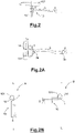
- the tube (101) is, for example, the tube arranged for supporting a seat (102), as per figure 1 , or a portion of the frame, for example the rear one, as per figure 1A .
- the tube is the one arranged for supporting the handlebar, or even any part of the bicycle (100) in its front or rear portion to which the headlight structure can be applied.
- the headlight structure (10) could be applicable, for example, to a tubular of the frame.
- the structure (10) could be applied advantageously to the free segment of this sloped section of the frame included between the wheel external perimeter and said vertical (or substantially vertical) tubular or, as shown in figure 1A , to the remaining section.
- said headlight structure (10) would be in a more rearward position with respect to the one that is explicitly depicted by figures 1 and 2 , wherein it is depicted in the under-seat post, thereby not hampering the user's thighs while cycling.
- the headlight (10) comprises an attachment portion (1) shaped to be connected to the tube (101) in a removable way, and an arm (3) which comprises a first end (3a) ( figure 2A ) connected to the attachment portion (1), and a second end 3b whereon a light source (5) is arranged, or more briefly a light (5).
- the attachment portion (1) is, for example, T-shaped ( figure 2A ).
- the attachment portion (1) is connected to the tube (101) through connection means (1d), such that the attachment portion is rotatably connected to the tube (101) ( figure 2B ), around at least one rotation axis X-X.
- the rotation axis is the longitudinal development axis of the tube supporting the seat (102).
- the light source (5) is orientable with respect to the tube (101), which identifies the rotation axis X-X ( figure 2 ), to project a beam of light according to at least one first direction A and one second direction B, which is angularly staggered around said rotation axis ( figure 2B ).
- connection means for example, provide a couple of tightening elements (1d) ( figure 2A ), such as cable ties of plastic material, arranged on the opposite part to each other and surrounding the attachment portion (1) and the tube (101) between each other, enabling a frictional rotation between the attachment portion (1) and the tube (101) itself.
- tightening elements (1d) such as cable ties of plastic material
- the attachment portion is a T-shaped tubular portion which is positioned into contact with and fixed to the tube by means of the cable ties (1d). Since the tube (101) is circular-shaped, the obtained coupling involves two cylindrical surfaces in frictional contact to each other and connected through the cable ties.
- the T-shaped attachment portion shown in figure 2A provides an upper and a lower groove (which are not depicted for simplicity's sake), each one is useful for forming a housing line for the cable ties (1d), so as to prevent the cable ties from sliding from their position, while using them, because of vibrations.
- a covering can be applied onto the tube (101), for example, a plastic material such as rubber or similar material, which enables to increase the friction between the attachment portion (1) and the tube (101), making the rotation firmer and fixed, and especially avoiding downward slips of the T-shaped attachment.
- the arm (3) even if it is depicted with a wavy shape in figures 1 and 1A , can also be in the shape of a straight arm, as shown in figure 2B .
- it can be of stiff material, such as plastic.
- Light (5) is connected to the end of the arm, and can be integrated into the arm (3) or, preferably, it can be a separated element connected to the arm (3) through connection means, such as screws, quick attachments, and the like. In this last case, light (5) can be removed advantageously from the arm (3), for example because of maintenance services.
- the light arranged into a suitable casing, can be of the rechargeable type, for example by a USB plug recharge system.
- it can be a battery system which has to be replaced when needed.
- the light is arranged so as to project orthogonally to the axis of the arm.
- the light beam in this case, is parallel to said longitudinal plane, thereby being visible to a vehicle which is driving along said plane direction.
- the light if it is applied in a removable way to the arm (3), can be applied both onto the right side and onto the left side of the arm (3) so as to be able to orient the light beam towards the rear part of the bicycle in any case, regardless of the rotation way of the arm (3).
- the headlight structure (10) comprises the attachment portion (1) formed to be connected in a removable way to the tube (101) of the bicycle (100), in this case, as it is shown in figure 1 , the tube supporting the seat (102).
- the attachment portion is such as to surround at least partially the tube (101), and to be fixed to it by a connection through cable ties (1d) ( figure 3 ).
- the coupling with the tube (101) provides two attachment portions (1a, 1b) which surround from the opposite part the tube (101) between each other.
- the counterposed attachment portions are tightened to each other, for example through screw elements (1c), in order to obtain a firm connection with the tube (101).
- a basis portion (4) which rotates around at least one rotation axis X-X, is rotatably connected to the attachment portion 1.
- the basis portion (4) is constrained to the attachment portion (1) so as to enable the rotation of the basis portion (4) with respect to the attachment portion (1).
- a light source (5) is arranged onto the basis portion (4).
- Light source (5) operates as a rear or front headlamp of the bicycle, and it can be oriented around the rotation axis. In this way, the light source can be oriented for example around the longitudinal development L ( figure 3A ) of the bicycle when it is running ( figure 1 ), and it is instead positioned angularly staggered with respect to the longitudinal development L ( figure 3B or 1A ) when the bicycle is stopped, for example, in order to signal the presence to any arriving car ( figure 1A ).
- the light source (5) is mounted on an arm (3).
- a first end (3a) of the arm is connected to the basis portion (4), while said light source (5) is arranged on a second end (3b).
- the basis portion (4) is rotatably connected to the attachment portion (1) through a rotation pin (6) which defines a single rotation axis X-X. ( Figure 4 ).
- the basis portion is connected through the pin (6) to the attachment portion, in correspondence of the corresponding attachments integral with it. Accordingly, in the assembled configuration, the basis portion can rotate around pin (6) which defines a rotation axis X-X, parallel to the tube (101).
- the basis portion (4) could be mounted orthogonally to the attachment portion (1), so that the rotation axis X-X is orthogonal with respect to the tube (101).
- the arrangement of the pin also enables to disassemble the basis portion (4) from the attachment portion (1), so as to make the headlight structure dismountable.
- the headlight structure can, for example, be removed when the bicycle is stopped or when it is not used.
- the basis portion (4) is connected to the attachment portion (1) through a spherical joint (7).
- the spherical joint (7) comprises a coupling between two male-female spherical portions, and therefore enables to orient the basis portion (4) in a multidirectional way, with respect to the attachment portion (1). In this way, the light source can substantially be oriented according to any direction.
- Figure 5A shows another embodiment with a spherical coupling.
- it provides a funnel-shaped basis portion (4), which provides an end (4') with a spherical female coupling portion on the internal part.
- the attachment portion comprises a threading on the external part.
- the end 3a' of the arm (3) is instead shaped with a spherical male portion, which engages into the spherical female portion.
- the locking of the two female-male portions occurs through a bush 4" providing a second female coupling portion on the internal part, so as to surround, with the portion of the end 4', the spherical end 3a' of the arm 3 when they are tightened to each other.
- arm 3 can be oriented angularly with respect to any direction.
- the headlight structure (10) as per this invention advantageously comprises the arm (3), which extends in a cantilevered way with respect to the basis portion (4).
- the arm (3) is a flexible element structured to be folded/shaped by a user in order to make it assume the desired position orienting light source (5) to a precise direction. After the deformation, the flexible element keeps the obtained configuration when the user releases it.
- said arm is made, for example, with a plurality of tubular elements joined to each other, and enabling a deformation of the arm after a deformation by a user.
- the obtained deformation is permanent and static when it is released.
- the flexible arm (3) enables to add further degrees of freedom for the pointing of the light source (5), positioned preferably on the end 3b of it.
- said basis portion houses a battery (8) to give power to said light source (5).
- the light source (5) is, for example, a led source powered by a battery (8), the battery is, for example housed into the basis portion (4).
Landscapes
- Engineering & Computer Science (AREA)
- Mechanical Engineering (AREA)
- Lighting Device Outwards From Vehicle And Optical Signal (AREA)
Applications Claiming Priority (1)
| Application Number | Priority Date | Filing Date | Title |
|---|---|---|---|
| IT102020000029606A IT202000029606A1 (it) | 2020-12-03 | 2020-12-03 | Struttura di faro di una bicicletta |
Publications (3)
| Publication Number | Publication Date |
|---|---|
| EP4008616A1 true EP4008616A1 (fr) | 2022-06-08 |
| EP4008616C0 EP4008616C0 (fr) | 2023-09-20 |
| EP4008616B1 EP4008616B1 (fr) | 2023-09-20 |
Family
ID=74669330
Family Applications (1)
| Application Number | Title | Priority Date | Filing Date |
|---|---|---|---|
| EP21210963.1A Active EP4008616B1 (fr) | 2020-12-03 | 2021-11-29 | Structure d'un phare de bicyclette |
Country Status (2)
| Country | Link |
|---|---|
| EP (1) | EP4008616B1 (fr) |
| IT (1) | IT202000029606A1 (fr) |
Cited By (1)
| Publication number | Priority date | Publication date | Assignee | Title |
|---|---|---|---|---|
| WO2024105399A1 (fr) * | 2022-11-18 | 2024-05-23 | Ward Robyn | Support |
Citations (5)
| Publication number | Priority date | Publication date | Assignee | Title |
|---|---|---|---|---|
| US5379197A (en) * | 1993-02-22 | 1995-01-03 | Conyers (Gpmrr) Enterprises, Inc. | Lighted bicycle safety device |
| NZ567218A (en) * | 2008-04-04 | 2009-01-31 | Peter Bain Carruthers | A bicycle safety device |
| DE202017102446U1 (de) * | 2016-05-17 | 2017-06-09 | Lee Chi Enterprises Co., Ltd. | Sattelstütze mit Verbindungshalterung und Verbindungshalterung für dieselbe |
| EP3521149A1 (fr) * | 2018-02-06 | 2019-08-07 | Blade Bikelights Limited | Ensemble de lampe de bicyclette |
| GB2574135A (en) * | 2019-08-06 | 2019-11-27 | Blade Bikelights Ltd | Mounting bracket for a bicycle light |
-
2020
- 2020-12-03 IT IT102020000029606A patent/IT202000029606A1/it unknown
-
2021
- 2021-11-29 EP EP21210963.1A patent/EP4008616B1/fr active Active
Patent Citations (5)
| Publication number | Priority date | Publication date | Assignee | Title |
|---|---|---|---|---|
| US5379197A (en) * | 1993-02-22 | 1995-01-03 | Conyers (Gpmrr) Enterprises, Inc. | Lighted bicycle safety device |
| NZ567218A (en) * | 2008-04-04 | 2009-01-31 | Peter Bain Carruthers | A bicycle safety device |
| DE202017102446U1 (de) * | 2016-05-17 | 2017-06-09 | Lee Chi Enterprises Co., Ltd. | Sattelstütze mit Verbindungshalterung und Verbindungshalterung für dieselbe |
| EP3521149A1 (fr) * | 2018-02-06 | 2019-08-07 | Blade Bikelights Limited | Ensemble de lampe de bicyclette |
| GB2574135A (en) * | 2019-08-06 | 2019-11-27 | Blade Bikelights Ltd | Mounting bracket for a bicycle light |
Cited By (1)
| Publication number | Priority date | Publication date | Assignee | Title |
|---|---|---|---|---|
| WO2024105399A1 (fr) * | 2022-11-18 | 2024-05-23 | Ward Robyn | Support |
Also Published As
| Publication number | Publication date |
|---|---|
| EP4008616C0 (fr) | 2023-09-20 |
| EP4008616B1 (fr) | 2023-09-20 |
| IT202000029606A1 (it) | 2022-06-03 |
Similar Documents
| Publication | Publication Date | Title |
|---|---|---|
| US6264351B1 (en) | Convertible orientation bicycle lamp | |
| US4760499A (en) | Adjustable automobile headlight assembly | |
| WO2004083026A1 (fr) | Dispositifs et systeme a signaux d'avertissement de securite pour vehicule destines a etre utilises sur une bicyclette, une moto ou un vehicule analogue | |
| CN102372049B (zh) | 前照灯的安装机构 | |
| EP4008616B1 (fr) | Structure d'un phare de bicyclette | |
| US7651251B2 (en) | Combined viewing mirror and turn signal lamp for automotive vehicles | |
| US11453454B2 (en) | Bicycle rearview mirror | |
| CA3054586A1 (fr) | Ensemble de phare a reglage rapide | |
| US9630303B2 (en) | Bicycle alignment tool | |
| JP3211860U (ja) | 投射角度を自動的に補正する車両用ヘッドライト | |
| US6964314B1 (en) | Three wheel motorcycle conversion assembly | |
| TWM631599U (zh) | 自行車握把 | |
| US11286014B2 (en) | Mounting bracket for a bicycle light | |
| US20220081067A1 (en) | Bicycle derailleur | |
| KR102403969B1 (ko) | 오토바이용 안개등 장착 구조 | |
| CA2608561A1 (fr) | Support d'accessoires de deflecteur pour motocyclette | |
| US5014641A (en) | Hazard warning device for vehicles | |
| BRPI0604373B1 (pt) | estrutura de suporte de farol dianteiro | |
| BR102014023656A2 (pt) | dispositivo medidor de motocicleta | |
| KR102283755B1 (ko) | 자동차 룸미러 모니터의 거치대 | |
| CN215794228U (zh) | 一种沙滩车后视镜 | |
| KR200401760Y1 (ko) | 헬멧용 백미러 | |
| CA2437458A1 (fr) | Systeme de phares modulaire pour vehicules recreatifs | |
| JP2547379Y2 (ja) | スクータ車両の灯火器取付構造 | |
| CN214929449U (zh) | 多角度监控车载摄像头 |
Legal Events
| Date | Code | Title | Description |
|---|---|---|---|
| PUAI | Public reference made under article 153(3) epc to a published international application that has entered the european phase |
Free format text: ORIGINAL CODE: 0009012 |
|
| STAA | Information on the status of an ep patent application or granted ep patent |
Free format text: STATUS: THE APPLICATION HAS BEEN PUBLISHED |
|
| AK | Designated contracting states |
Kind code of ref document: A1 Designated state(s): AL AT BE BG CH CY CZ DE DK EE ES FI FR GB GR HR HU IE IS IT LI LT LU LV MC MK MT NL NO PL PT RO RS SE SI SK SM TR |
|
| STAA | Information on the status of an ep patent application or granted ep patent |
Free format text: STATUS: REQUEST FOR EXAMINATION WAS MADE |
|
| 17P | Request for examination filed |
Effective date: 20221004 |
|
| RBV | Designated contracting states (corrected) |
Designated state(s): AL AT BE BG CH CY CZ DE DK EE ES FI FR GB GR HR HU IE IS IT LI LT LU LV MC MK MT NL NO PL PT RO RS SE SI SK SM TR |
|
| GRAP | Despatch of communication of intention to grant a patent |
Free format text: ORIGINAL CODE: EPIDOSNIGR1 |
|
| STAA | Information on the status of an ep patent application or granted ep patent |
Free format text: STATUS: GRANT OF PATENT IS INTENDED |
|
| INTG | Intention to grant announced |
Effective date: 20230509 |
|
| P01 | Opt-out of the competence of the unified patent court (upc) registered |
Effective date: 20230418 |
|
| P02 | Opt-out of the competence of the unified patent court (upc) changed |
Effective date: 20230621 |
|
| GRAS | Grant fee paid |
Free format text: ORIGINAL CODE: EPIDOSNIGR3 |
|
| GRAA | (expected) grant |
Free format text: ORIGINAL CODE: 0009210 |
|
| STAA | Information on the status of an ep patent application or granted ep patent |
Free format text: STATUS: THE PATENT HAS BEEN GRANTED |
|
| AK | Designated contracting states |
Kind code of ref document: B1 Designated state(s): AL AT BE BG CH CY CZ DE DK EE ES FI FR GB GR HR HU IE IS IT LI LT LU LV MC MK MT NL NO PL PT RO RS SE SI SK SM TR |
|
| REG | Reference to a national code |
Ref country code: GB Ref legal event code: FG4D |
|
| REG | Reference to a national code |
Ref country code: CH Ref legal event code: EP |
|
| REG | Reference to a national code |
Ref country code: IE Ref legal event code: FG4D |
|
| REG | Reference to a national code |
Ref country code: DE Ref legal event code: R096 Ref document number: 602021005273 Country of ref document: DE |
|
| U01 | Request for unitary effect filed |
Effective date: 20231006 |
|
| U07 | Unitary effect registered |
Designated state(s): AT BE BG DE DK EE FI FR IT LT LU LV MT NL PT SE SI Effective date: 20231017 |
|
| P04 | Withdrawal of opt-out of the competence of the unified patent court (upc) registered |
Effective date: 20231013 |
|
| U20 | Renewal fee for the european patent with unitary effect paid |
Year of fee payment: 3 Effective date: 20231020 |
|
| PG25 | Lapsed in a contracting state [announced via postgrant information from national office to epo] |
Ref country code: GR Free format text: LAPSE BECAUSE OF FAILURE TO SUBMIT A TRANSLATION OF THE DESCRIPTION OR TO PAY THE FEE WITHIN THE PRESCRIBED TIME-LIMIT Effective date: 20231221 |
|
| PG25 | Lapsed in a contracting state [announced via postgrant information from national office to epo] |
Ref country code: RS Free format text: LAPSE BECAUSE OF FAILURE TO SUBMIT A TRANSLATION OF THE DESCRIPTION OR TO PAY THE FEE WITHIN THE PRESCRIBED TIME-LIMIT Effective date: 20230920 Ref country code: NO Free format text: LAPSE BECAUSE OF FAILURE TO SUBMIT A TRANSLATION OF THE DESCRIPTION OR TO PAY THE FEE WITHIN THE PRESCRIBED TIME-LIMIT Effective date: 20231220 Ref country code: HR Free format text: LAPSE BECAUSE OF FAILURE TO SUBMIT A TRANSLATION OF THE DESCRIPTION OR TO PAY THE FEE WITHIN THE PRESCRIBED TIME-LIMIT Effective date: 20230920 Ref country code: GR Free format text: LAPSE BECAUSE OF FAILURE TO SUBMIT A TRANSLATION OF THE DESCRIPTION OR TO PAY THE FEE WITHIN THE PRESCRIBED TIME-LIMIT Effective date: 20231221 |
|
| PG25 | Lapsed in a contracting state [announced via postgrant information from national office to epo] |
Ref country code: IS Free format text: LAPSE BECAUSE OF FAILURE TO SUBMIT A TRANSLATION OF THE DESCRIPTION OR TO PAY THE FEE WITHIN THE PRESCRIBED TIME-LIMIT Effective date: 20240120 |
|
| PG25 | Lapsed in a contracting state [announced via postgrant information from national office to epo] |
Ref country code: ES Free format text: LAPSE BECAUSE OF FAILURE TO SUBMIT A TRANSLATION OF THE DESCRIPTION OR TO PAY THE FEE WITHIN THE PRESCRIBED TIME-LIMIT Effective date: 20230920 |
|
| PG25 | Lapsed in a contracting state [announced via postgrant information from national office to epo] |
Ref country code: SM Free format text: LAPSE BECAUSE OF FAILURE TO SUBMIT A TRANSLATION OF THE DESCRIPTION OR TO PAY THE FEE WITHIN THE PRESCRIBED TIME-LIMIT Effective date: 20230920 Ref country code: RO Free format text: LAPSE BECAUSE OF FAILURE TO SUBMIT A TRANSLATION OF THE DESCRIPTION OR TO PAY THE FEE WITHIN THE PRESCRIBED TIME-LIMIT Effective date: 20230920 Ref country code: IS Free format text: LAPSE BECAUSE OF FAILURE TO SUBMIT A TRANSLATION OF THE DESCRIPTION OR TO PAY THE FEE WITHIN THE PRESCRIBED TIME-LIMIT Effective date: 20240120 Ref country code: ES Free format text: LAPSE BECAUSE OF FAILURE TO SUBMIT A TRANSLATION OF THE DESCRIPTION OR TO PAY THE FEE WITHIN THE PRESCRIBED TIME-LIMIT Effective date: 20230920 Ref country code: CZ Free format text: LAPSE BECAUSE OF FAILURE TO SUBMIT A TRANSLATION OF THE DESCRIPTION OR TO PAY THE FEE WITHIN THE PRESCRIBED TIME-LIMIT Effective date: 20230920 Ref country code: SK Free format text: LAPSE BECAUSE OF FAILURE TO SUBMIT A TRANSLATION OF THE DESCRIPTION OR TO PAY THE FEE WITHIN THE PRESCRIBED TIME-LIMIT Effective date: 20230920 |
|
| PG25 | Lapsed in a contracting state [announced via postgrant information from national office to epo] |
Ref country code: PL Free format text: LAPSE BECAUSE OF FAILURE TO SUBMIT A TRANSLATION OF THE DESCRIPTION OR TO PAY THE FEE WITHIN THE PRESCRIBED TIME-LIMIT Effective date: 20230920 |
|
| REG | Reference to a national code |
Ref country code: DE Ref legal event code: R097 Ref document number: 602021005273 Country of ref document: DE |
|
| PG25 | Lapsed in a contracting state [announced via postgrant information from national office to epo] |
Ref country code: MC Free format text: LAPSE BECAUSE OF FAILURE TO SUBMIT A TRANSLATION OF THE DESCRIPTION OR TO PAY THE FEE WITHIN THE PRESCRIBED TIME-LIMIT Effective date: 20230920 |
|
| PLBE | No opposition filed within time limit |
Free format text: ORIGINAL CODE: 0009261 |
|
| STAA | Information on the status of an ep patent application or granted ep patent |
Free format text: STATUS: NO OPPOSITION FILED WITHIN TIME LIMIT |
|
| PG25 | Lapsed in a contracting state [announced via postgrant information from national office to epo] |
Ref country code: MC Free format text: LAPSE BECAUSE OF FAILURE TO SUBMIT A TRANSLATION OF THE DESCRIPTION OR TO PAY THE FEE WITHIN THE PRESCRIBED TIME-LIMIT Effective date: 20230920 |
|
| 26N | No opposition filed |
Effective date: 20240621 |
|
| REG | Reference to a national code |
Ref country code: IE Ref legal event code: MM4A |
|
| U20 | Renewal fee for the european patent with unitary effect paid |
Year of fee payment: 4 Effective date: 20240902 |
|
| PG25 | Lapsed in a contracting state [announced via postgrant information from national office to epo] |
Ref country code: IE Free format text: LAPSE BECAUSE OF NON-PAYMENT OF DUE FEES Effective date: 20231129 |
|
| PG25 | Lapsed in a contracting state [announced via postgrant information from national office to epo] |
Ref country code: IE Free format text: LAPSE BECAUSE OF NON-PAYMENT OF DUE FEES Effective date: 20231129 |
|
| P05 | Withdrawal of opt-out of the competence of the unified patent court (upc) changed |
Free format text: CASE NUMBER: APP_580053/2023 Effective date: 20231017 |
|
| REG | Reference to a national code |
Ref country code: CH Ref legal event code: PL |
|
| REG | Reference to a national code |
Ref country code: CH Ref legal event code: PL |
|
| PG25 | Lapsed in a contracting state [announced via postgrant information from national office to epo] |
Ref country code: CH Free format text: LAPSE BECAUSE OF NON-PAYMENT OF DUE FEES Effective date: 20241130 |
|
| PG25 | Lapsed in a contracting state [announced via postgrant information from national office to epo] |
Ref country code: CY Free format text: LAPSE BECAUSE OF FAILURE TO SUBMIT A TRANSLATION OF THE DESCRIPTION OR TO PAY THE FEE WITHIN THE PRESCRIBED TIME-LIMIT; INVALID AB INITIO Effective date: 20211129 |
|
| U20 | Renewal fee for the european patent with unitary effect paid |
Year of fee payment: 5 Effective date: 20250901 |
|
| PG25 | Lapsed in a contracting state [announced via postgrant information from national office to epo] |
Ref country code: TR Free format text: LAPSE BECAUSE OF FAILURE TO SUBMIT A TRANSLATION OF THE DESCRIPTION OR TO PAY THE FEE WITHIN THE PRESCRIBED TIME-LIMIT Effective date: 20230920 |
|
| PG25 | Lapsed in a contracting state [announced via postgrant information from national office to epo] |
Ref country code: HU Free format text: LAPSE BECAUSE OF FAILURE TO SUBMIT A TRANSLATION OF THE DESCRIPTION OR TO PAY THE FEE WITHIN THE PRESCRIBED TIME-LIMIT; INVALID AB INITIO Effective date: 20211129 |