EP4008621A1 - Agencement de pignon multiple pour bicyclettes - Google Patents
Agencement de pignon multiple pour bicyclettes Download PDFInfo
- Publication number
- EP4008621A1 EP4008621A1 EP21020547.2A EP21020547A EP4008621A1 EP 4008621 A1 EP4008621 A1 EP 4008621A1 EP 21020547 A EP21020547 A EP 21020547A EP 4008621 A1 EP4008621 A1 EP 4008621A1
- Authority
- EP
- European Patent Office
- Prior art keywords
- pinion
- sprocket
- damping body
- assembly
- arrangement
- Prior art date
- Legal status (The legal status is an assumption and is not a legal conclusion. Google has not performed a legal analysis and makes no representation as to the accuracy of the status listed.)
- Granted
Links
Images



Classifications
-
- B—PERFORMING OPERATIONS; TRANSPORTING
- B62—LAND VEHICLES FOR TRAVELLING OTHERWISE THAN ON RAILS
- B62M—RIDER PROPULSION OF WHEELED VEHICLES OR SLEDGES; POWERED PROPULSION OF SLEDGES OR SINGLE-TRACK CYCLES; TRANSMISSIONS SPECIALLY ADAPTED FOR SUCH VEHICLES
- B62M9/00—Transmissions characterised by use of an endless chain, belt, or the like
- B62M9/04—Transmissions characterised by use of an endless chain, belt, or the like of changeable ratio
- B62M9/06—Transmissions characterised by use of an endless chain, belt, or the like of changeable ratio using a single chain, belt, or the like
- B62M9/10—Transmissions characterised by use of an endless chain, belt, or the like of changeable ratio using a single chain, belt, or the like involving different-sized wheels, e.g. rear sprocket chain wheels selectively engaged by the chain, belt, or the like
-
- B—PERFORMING OPERATIONS; TRANSPORTING
- B62—LAND VEHICLES FOR TRAVELLING OTHERWISE THAN ON RAILS
- B62M—RIDER PROPULSION OF WHEELED VEHICLES OR SLEDGES; POWERED PROPULSION OF SLEDGES OR SINGLE-TRACK CYCLES; TRANSMISSIONS SPECIALLY ADAPTED FOR SUCH VEHICLES
- B62M9/00—Transmissions characterised by use of an endless chain, belt, or the like
- B62M9/04—Transmissions characterised by use of an endless chain, belt, or the like of changeable ratio
- B62M9/06—Transmissions characterised by use of an endless chain, belt, or the like of changeable ratio using a single chain, belt, or the like
- B62M9/10—Transmissions characterised by use of an endless chain, belt, or the like of changeable ratio using a single chain, belt, or the like involving different-sized wheels, e.g. rear sprocket chain wheels selectively engaged by the chain, belt, or the like
- B62M9/12—Transmissions characterised by use of an endless chain, belt, or the like of changeable ratio using a single chain, belt, or the like involving different-sized wheels, e.g. rear sprocket chain wheels selectively engaged by the chain, belt, or the like the chain, belt, or the like being laterally shiftable, e.g. using a rear derailleur
- B62M9/121—Rear derailleurs
-
- B—PERFORMING OPERATIONS; TRANSPORTING
- B62—LAND VEHICLES FOR TRAVELLING OTHERWISE THAN ON RAILS
- B62M—RIDER PROPULSION OF WHEELED VEHICLES OR SLEDGES; POWERED PROPULSION OF SLEDGES OR SINGLE-TRACK CYCLES; TRANSMISSIONS SPECIALLY ADAPTED FOR SUCH VEHICLES
- B62M9/00—Transmissions characterised by use of an endless chain, belt, or the like
- B62M9/04—Transmissions characterised by use of an endless chain, belt, or the like of changeable ratio
- B62M9/06—Transmissions characterised by use of an endless chain, belt, or the like of changeable ratio using a single chain, belt, or the like
- B62M9/10—Transmissions characterised by use of an endless chain, belt, or the like of changeable ratio using a single chain, belt, or the like involving different-sized wheels, e.g. rear sprocket chain wheels selectively engaged by the chain, belt, or the like
- B62M9/12—Transmissions characterised by use of an endless chain, belt, or the like of changeable ratio using a single chain, belt, or the like involving different-sized wheels, e.g. rear sprocket chain wheels selectively engaged by the chain, belt, or the like the chain, belt, or the like being laterally shiftable, e.g. using a rear derailleur
- B62M9/121—Rear derailleurs
- B62M9/128—Accessories, e.g. protectors
-
- F—MECHANICAL ENGINEERING; LIGHTING; HEATING; WEAPONS; BLASTING
- F16—ENGINEERING ELEMENTS AND UNITS; GENERAL MEASURES FOR PRODUCING AND MAINTAINING EFFECTIVE FUNCTIONING OF MACHINES OR INSTALLATIONS; THERMAL INSULATION IN GENERAL
- F16F—SPRINGS; SHOCK-ABSORBERS; MEANS FOR DAMPING VIBRATION
- F16F15/00—Suppression of vibrations in systems; Means or arrangements for avoiding or reducing out-of-balance forces, e.g. due to motion
- F16F15/10—Suppression of vibrations in rotating systems by making use of members moving with the system
-
- B—PERFORMING OPERATIONS; TRANSPORTING
- B60—VEHICLES IN GENERAL
- B60B—VEHICLE WHEELS; CASTORS; AXLES FOR WHEELS OR CASTORS; INCREASING WHEEL ADHESION
- B60B2200/00—Type of product being used or applied
- B60B2200/40—Articles of daily use
- B60B2200/47—Physical activity equipment, e.g. leisure or sports articles
-
- B—PERFORMING OPERATIONS; TRANSPORTING
- B60—VEHICLES IN GENERAL
- B60B—VEHICLE WHEELS; CASTORS; AXLES FOR WHEELS OR CASTORS; INCREASING WHEEL ADHESION
- B60B27/00—Hubs
- B60B27/02—Hubs adapted to be rotatably arranged on axle
- B60B27/04—Hubs adapted to be rotatably arranged on axle housing driving means, e.g. sprockets
-
- B—PERFORMING OPERATIONS; TRANSPORTING
- B60—VEHICLES IN GENERAL
- B60B—VEHICLE WHEELS; CASTORS; AXLES FOR WHEELS OR CASTORS; INCREASING WHEEL ADHESION
- B60B2900/00—Purpose of invention
- B60B2900/10—Reduction of
- B60B2900/131—Vibrations
-
- B—PERFORMING OPERATIONS; TRANSPORTING
- B60—VEHICLES IN GENERAL
- B60B—VEHICLE WHEELS; CASTORS; AXLES FOR WHEELS OR CASTORS; INCREASING WHEEL ADHESION
- B60B2900/00—Purpose of invention
- B60B2900/10—Reduction of
- B60B2900/133—Noise
-
- F—MECHANICAL ENGINEERING; LIGHTING; HEATING; WEAPONS; BLASTING
- F16—ENGINEERING ELEMENTS AND UNITS; GENERAL MEASURES FOR PRODUCING AND MAINTAINING EFFECTIVE FUNCTIONING OF MACHINES OR INSTALLATIONS; THERMAL INSULATION IN GENERAL
- F16F—SPRINGS; SHOCK-ABSORBERS; MEANS FOR DAMPING VIBRATION
- F16F2232/00—Nature of movement
- F16F2232/02—Rotary
-
- F—MECHANICAL ENGINEERING; LIGHTING; HEATING; WEAPONS; BLASTING
- F16—ENGINEERING ELEMENTS AND UNITS; GENERAL MEASURES FOR PRODUCING AND MAINTAINING EFFECTIVE FUNCTIONING OF MACHINES OR INSTALLATIONS; THERMAL INSULATION IN GENERAL
- F16H—GEARING
- F16H55/00—Elements with teeth or friction surfaces for conveying motion; Worms, pulleys or sheaves for gearing mechanisms
- F16H55/02—Toothed members; Worms
- F16H55/30—Chain-wheels
Definitions
- the present invention relates to a multiple sprocket assembly for bicycles. Such a multiple sprocket assembly can be attached to a rear wheel axle assembly of a bicycle. In addition, the present invention relates to a rear wheel axle arrangement of a bicycle with such a multiple sprocket arrangement.
- a bicycle may be equipped with a drive assembly, such as a chain drive.
- Bicycle drivetrains can be used to transfer torque from a rider to a rear wheel of the bicycle to propel the bicycle.
- a drive assembly may transfer torque from a front sprocket assembly to a rear sprocket via a chain to drive a rear idler wheel.
- Such a drive arrangement can be referred to as a drive train.
- Bicycle sprocket assemblies may include one sprocket or multiple individual sprockets.
- the front sprockets are commonly referred to as chainrings.
- Chainrings can be attached using a variety of fasteners.
- a chainring can, for example, be attached with chainring bolts or mounted directly on the crank of a bicycle.
- the rear sprockets are often referred to as sprockets.
- a plurality of rear sprockets or sprockets may be referred to as a multiple sprocket assembly, sprocket assembly, cassette, sprocket cassette, or sprocket pack.
- Such a multiple sprocket assembly or cassette is typically configured to be attached to a freehub body of a rear wheel.
- the drive arrangement can also include a rear derailleur, with which the chain can be switched between the individual sprockets of the multiple sprocket arrangement. Different gears or gears can thus be engaged with the rear derailleur, with the respective gear depending on which sprocket of the multiple sprocket arrangement the chain is located on.
- sprocket assemblies are, for example, from U.S. 10,112,681 B2 or EP 2 319 752 A2 known.
- the multiple sprocket assembly for attachment to a rear wheel axle assembly of a bicycle includes at least one first sprocket, at least one second sprocket, and at least one damping body.
- the at least one damping body extends from the at least one first sprocket in the direction of the at least one second sprocket, the at least one damping body resting against at least one axial side surface of the first sprocket.
- the at least one damping body serves to improve the acoustics of the multiple sprocket arrangement.
- the at least one damping body improves the acoustics in that vibrations and/or sound can be damped with the at least one damping body.
- the at least one damping body is in contact with at least one axial side face of a pinion of the multiple pinion arrangement for vibration damping or noise damping.
- the at least one damping body can be supported at least on the axial side face of the first pinion.
- the at least one damping body can be attached at least to the axial side surface of the first pinion.
- the at least one damping body can contact the at least one second pinion at least in the radial direction.
- the at least one damping body can be supported in the radial direction on at least one further pinion of the multiple pinion arrangement, wherein the at least one further pinion can be a pinion adjacent to the first pinion or a pinion further away from the first pinion in the axial direction.
- the at least one damping body can at least partially contact a radially inner edge or a radially inner surface of the corresponding pinion.
- the radial contact between the at least Damping body and the at least one second pinion can contribute to the centering of at least one damping body during assembly.
- the at least one damping body can be supported in the axial direction at least on the mutually facing axial side surfaces of the first pinion and the second pinion.
- the at least one damping body can also be supported on a further pinion and/or a pinion assembly of the multiple pinion arrangement. It is also conceivable that the at least one damping body is supported on a further component, such as a closure body, of the multiple sprocket arrangement.
- the at least one damping body can be supported, in particular in the axial direction, at least on the axial side surfaces of the first pinion and the second pinion.
- the at least one damping body can have axial side faces and/or axial end faces with which it can be supported on the axial side faces of the pinion.
- the first pinion gear and the second pinion gear may be pinion gears arranged at a central portion of the multiple pinion assembly in the axial direction.
- the at least one first sprocket may have a diameter smaller than the diameter of the largest sprocket but larger than the diameter of the smallest sprocket.
- the second sprocket can have a diameter that is larger or smaller than the diameter of the first sprocket.
- At least the at least one first sprocket of the multiple sprocket arrangement can be designed for the torque-transmitting coupling of the multiple sprocket arrangement to the rear axle of the bicycle.
- the multiple sprocket arrangement can be supported on the rear axle of the bicycle at least via the at least one first sprocket.
- the at least one first sprocket can, for example, be coupled in a torque-transmitting manner to a driver body on the rear axle of the bicycle and can be supported on this driver body.
- several sprockets of the multiple sprocket arrangement can be coupled in a torque-transmitting manner to the rear axle of the bicycle and in particular to a driver body.
- the at least one first sprocket can form a final sprocket of the multiple sprocket arrangement.
- the at least one first pinion can be the largest pinion, ie the pinion with the largest number of teeth and/or the largest diameter.
- Such a final sprocket can use the multiple sprocket arrangement torque-transmittingly couple to the rear wheel axle assembly of the bicycle.
- the multiple sprocket arrangement can be supported in the radial direction on the rear wheel axle arrangement of the bicycle via the final sprocket.
- the at least one damping body can be held between the at least one first sprocket and the at least one second sprocket via a press fit.
- the at least one damping body can be oversized in the axial direction.
- the axial extent of the damping body can be greater than the axial distance between the axial side faces of the first pinion and the second pinion.
- the at least one damping body can be oversized in the radial direction.
- the outside diameter of the at least one damping body can be larger, at least in some areas, than the inside diameter of at least one sprocket of the multiple sprocket arrangement.
- the at least one damping body can be permanently connected to the first pinion and/or the second pinion. With a permanently fixed connection of the damping body to the first pinion and/or the second pinion, a contact area between the damping body and at least one of the first pinion or second pinion can be enlarged, so that the damping effect of the at least one damping body can be further increased.
- the at least one damping body can be glued to the first sprocket and/or the second sprocket.
- the at least one damping body can, for example, be glued to an axial side face of the first pinion and, starting from this axial side face, can extend in the direction of an axial side face of the second pinion.
- the at least one damping body can only be attached to the axial side surface of the at least one first pinion. It is also conceivable that the damping body only contacts the axial side surface of the first pinion.
- the at least one damping body can be glued to the axial side faces of the first pinion and the second pinion.
- the at least one damping body can, for example, with be bonded to an axial side face of the first pinion and extend from this axial side face towards a radially inner edge or face of the second pinion.
- the at least one damping body can rest against this radially inner edge or this radially inner surface at least in sections.
- the at least one damping body can, for example, rest against the radially inner edge or the radially inner surface of the second pinion with its radially outer surface.
- the at least one first pinion gear can have a toothed ring, a coupling opening and a connection area which connects the toothed ring to the coupling opening.
- the coupling opening can be designed for torque-transmitting coupling of the multiple sprocket arrangement to a rear wheel axle of the bicycle.
- the coupling opening can have a torque transmission contour which can be coupled to a complementary contour on the rear wheel axle arrangement or a driver body of the rear wheel axle arrangement.
- the toothed ring extends radially outward around the coupling opening and is connected to the coupling opening via the connecting area.
- the connection area between the toothed ring and the coupling opening can be formed by one pinion arm or several pinion arms.
- the at least one damping body can be arranged on the toothed ring of the first pinion.
- the at least one damping body can be arranged on a radially outer area (but radially inside the teeth of the pinion) of the first pinion.
- the second sprocket can be the next smaller sprocket, for example.
- the at least one damping body can be arranged between the first pinion and the second pinion, which is formed by the next smaller pinion.
- the at least one damping body can be arranged on the connection area of the first sprocket.
- the connection area can be located radially inside the toothed ring.
- the at least one damping body can be arranged in the radial direction between the toothed ring and the coupling opening of the first pinion.
- the at least one damping body can be arranged in a central area of the radial extent of the first pinion.
- the at least one damping body can extend from the connection area of the first sprocket in the direction of the second sprocket, which is located in the axial direction in a central region of the multiple sprocket arrangement or represents one of the medium-sized sprockets of the multiple sprocket arrangement.
- At least one The contact area between the damping body and the first pinion and/or the damping body and the second pinion can be increased, so that the damping effect of the at least one damping body can be further increased.
- dirt can be pushed out by the chain in the radial direction inwards of the multiple sprocket arrangement, as a result of which shifting errors due to foreign bodies can be avoided.
- the damping body which is arranged further inwards in the radial direction, can be protected against mechanical loads from the outside, for example due to a high-pressure cleaner, or due to foreign bodies/dirt.
- the at least one damping body can extend in the axial direction along at least one further sprocket to the second sprocket. Starting from the first pinion, the at least one damping body can extend radially inside the at least one further pinion to the second pinion. The at least one damping body can be designed in such a way that it does not contact the at least one additional pinion.
- the at least one damping body can be ring-shaped.
- the at least one damping body can have axial side faces and/or axial end faces.
- the at least one damping body can have a predetermined axial extension.
- the at least one damping body can have at least one radially outer surface and at least one radially inner surface.
- the radially inner surface and/or the radially outer surface of the at least one damping body can be in contact with at least the at least one second sprocket or a further component of the multiple sprocket arrangement in the radial direction.
- the at least one radially outer surface and the at least one radially inner surface are not in contact with the multiple pinion arrangement or a pinion, or only in some areas.
- a continuous or planar contact can only exist between the at least one damping body and at least one axial side face of the first pinion and/or the second pinion.
- the at least one damping body can have at least one recess on at least one radially outer surface or one radially outer edge and/or on at least one radially inner surface or one radially inner edge.
- the at least one recess can be provided, for example, for the bolts for connecting two adjacent pinions.
- the at least one damping body can rest against the bolts in the area of the recesses.
- the at least one recess can be provided on the radially inner surface of the at least one damping body for one of the pinion arms.
- the at least one damping body can be made of an elastic plastic or an elastic plastic foam.
- the at least one damping body can be made from a polyurethane foam, for example.
- the damping body can be made from a plastic foam, for example, which is marketed under the name Cellasto® .
- the damping body can, for example, also be made from a plastic that is marketed under the name Sylomer® .
- the plastic foam can be closed-cell to reduce the absorption of moisture and dirt.
- the multiple sprocket arrangement can be composed of several individual sprockets that are connected to one another via pins or bolts.
- the multiple sprocket assembly may also include sprocket assemblies of integrally formed sprockets or sprockets welded together.
- the smallest sprockets of a multiple sprocket assembly can form such a sprocket assembly.
- These sprocket assemblies can be connected to individual sprockets or to another sprocket assembly via bolts or pins.
- the final sprocket of the multiple sprocket arrangement can be designed as a single sprocket and the remaining sprockets of the multiple sprocket arrangement can form a sprocket assembly of the type described above.
- the present invention also relates to a rear wheel assembly for a bicycle.
- the rear wheel assembly includes a rear wheel having a rear wheel axle configured for attachment to a bicycle frame, a driver body rotatably mounted on the rear wheel axle, and a multiple sprocket assembly of the type described above coupleable to the driver body in a drive direction.
- the driver body can be coupled to the rear wheel axle via a freewheel device.
- the driver body can also be referred to as a "freewheel body”.
- the spokes and/or composite surfaces of a rear wheel can contribute to the generation of vibration and/or noise emissions that can result in undesirable noise when riding a bicycle.
- the air pressure in the rear tires can also contribute to the development of this unwanted noise.
- FIG 1 shows an example of a bicycle 10.
- the bicycle 10 includes a bicycle frame 12, a front wheel 14, a rear wheel 16, a handlebar 18, a saddle 20 and a drive assembly 22.
- the drive assembly 22 includes a chain 24, a rear derailleur 26, a front sprocket 28 and a rear multiple sprocket assembly 30 having a plurality of sprockets 32.
- Each sprocket 32 has a plurality of teeth engageable with the chain 24 on its outer periphery.
- the front sprocket 28 is connected to a crank assembly 34 . Pedals are provided on the crank assembly 34 .
- the directional information used below, right/left and front/back, relates to a bicycle 10 in the direction of travel, i.e. it corresponds to the rider’s perspective on the bicycle 10.
- the front wheel 14 is coupled to the bicycle frame 12 via a front fork 35 .
- the front fork 35 is connected to the handlebar 16 .
- the bicycle frame 12 typically has left and right rear dropouts or eyelets between which the rear wheel 16 is mounted.
- the rear wheel 16 rotates about the axis of rotation A together with the multiple sprocket assembly 30.
- the term "axial" refers to the axis of rotation A of the multiple sprocket assembly 30 or a direction parallel thereto, which is in 1 runs perpendicular to the plane of the drawing.
- the diameter of the pinions 32 decreases outwards in the axial direction of the axis A, ie the largest pinion is axially further inwards than the smaller pinions.
- the multiple sprocket assembly 30 is torque-transmittingly coupled to and fixed to a driver body (not shown) of the axle assembly on the rear wheel 16 of the bicycle 10 .
- a torque can be transmitted to the axle arrangement on the rear wheel 16 and thus to the rear wheel 16 of the bicycle 10 via the multiple pinion arrangement 30 .
- the rear derailleur 26 can shift the chain 24 between the individual sprockets 32 of the multiple sprocket arrangement 30, ie the chain 24 can be moved from one sprocket 32 to the next by means of the rear derailleur 26. Different gears or gears can thus be engaged with the rear derailleur 26, the respective gear depending on which sprocket 32 of the multiple sprocket arrangement 30 the chain 24 is located.
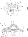
- FIGs 2, 3 and 4 show different views of a multiple sprocket assembly 30 according to a first embodiment, wherein figure 3 a sectional view along line III-III in Figure 2 and Figure 4 a sectional view along line IV-IV in figure 3 indicates.
- the multiple sprocket assembly 30 includes a final sprocket 32a.
- the final pinion 32a serves to transmit torque from the multi-pinion arrangement 30 to the axle arrangement on the rear wheel 14 (see FIG figure 1 ).
- the multiple pinion arrangement 30 can be supported on the rear wheel axle via the final pinion 32a.
- the final sprocket 32a represents the sprocket with the largest diameter of the multiple sprocket arrangement 30.
- a plurality of further sprockets 32b to 32I are connected to the final sprocket 32a (see FIG figure 3 ).
- the diameter of the pinions 32b to 32l decreases outwards in the axial direction, starting from the closing pinion 32a.
- the final sprocket 32a has a coupling opening 36, with which the multiple sprocket assembly 30 can be plugged onto an axle assembly on the rear wheel 16.
- the coupling opening 36 has a torque transmission contour on its inner circumference, via which the multiple pinion arrangement 30 can be coupled in a torque-transmitting manner to a driver body (not shown) of the axle arrangement on the rear wheel 16 .
- the torque transmission contour comprises a plurality of projections 38 which extend inward in the radial direction.
- the driver body of the axle arrangement on the rear wheel 16 has a contour on its outer surface which is designed to complement the torque transmission contour on the coupling opening 36 of the final pinion 32a.
- the final pinion 32a also has pinion arms 40 which extend between the coupling opening 36 and a toothed ring 42 with the pinion teeth on the outer circumference.
- the pinion arms 40 connect the coupling opening 36 to the radially outer toothed ring 42, i.e. the pinion arms 40 are formed in a connecting region between the toothed ring 42 and the coupling opening 36.
- Openings 44 are formed in the toothed ring 42 into which pins or bolts 46 are inserted for connection to the next smaller sprocket 32b.
- the toothed ring 42 also has a plurality of openings 48 .
- the openings 48 contribute, among other things, to the weight saving 30 .
- several of the pinions 32b to 32l have identical or similar openings 48.
- the openings 48 are formed between the openings 44 for the bolts 46 .
- the multiple pinion arrangement 30 has a damping body 50 .
- the damping body 50 serves to dampen vibrations and noise.
- the acoustics of the multi-sprocket arrangement 30 can be improved by the damping body 50, i. H. unwanted noise occurring during operation of the multiple sprocket arrangement 30 can be reduced.
- the damping body 50 is arranged between the final pinion 32a and the next smaller pinion 32b.
- the damping body 50 bears against an axial side surface of the final pinion 32a and against an axial side surface of the next smaller pinion 32b.
- the axial surface of the next smaller gear 32b faces the final gear 32a.
- the damping body 50 protrudes inward in the radial direction beyond the toothed ring 42 of the final pinion 32a.
- the shape of the damping body 50 is particularly figure 4 recognizable, in which the damping body 50 along the section line IV-IV according to figure 3 is shown cut.
- the damping body 50 is essentially ring-shaped.
- the damping body 50 extends along the pinion 32b.
- the radial extension of the damping body 50 is smaller than the radial extension of the annular pinion 23b.
- the damping body 50 rests against the pinion 32b.
- the damping body 50 has recesses 52 in which the bolts 46 for connecting the final pinion 32a and the pinion 32b extend.
- the recesses 52 are formed on the radially outer edge of the damping body 50 .
- the damping body 50 also has further recesses 54 .
- the recesses 54 are provided on the radially inner edge of the damping body 50 .
- the recesses 54 are formed at positions on the damping body 50 at which the pinion arms 40 extend from the toothed ring 42 in the direction of the coupling opening 36 .
- the damping body 50 may be attached to the multiple sprocket assembly 30 via an interference fit.
- the damping body 50 can be inserted and compressed between the final sprocket 32a and the next smaller sprocket 32b. In this way, the damping body 50 is attached to the multiple sprocket assembly 30 via an interference fit.
- the damping body 50 Prior to attachment or assembly, the damping body 50 has a greater axial extent, which is greater than the axial distance between the final pinion 32a and the next smaller pinion 32b.
- the damping body 50 has in Initial state thus an axial oversize before it is compressed during assembly.
- the multiple sprocket assembly 30 also includes a closure body or closure tube 56.
- the closure body 56 serves to connect the multiple sprocket assembly 30 to a driver body (not shown) which is rotatably mounted on the rear wheel axle A.
- the closure body 56 has an internal thread 58 .
- the multiple pinion arrangement 30 can be screwed to the driver body via the internal thread 58 .
- the closure body 56 also has a portion 60 that contacts the closure gear 32a. When the closure body 56 is screwed to a driver body, the section 60 holds the final pinion 32a and thus the entire multiple pinion arrangement 30 in the axial direction in its predetermined position on the driver body.
- the closure body 56 also has supporting projections 62 which extend in the axial direction.
- the support projections 62 support the multiple sprocket assembly 30 in the radial direction.
- the supporting projections 62 can contact the pinions 32k and 32l.
- the support projections 62 extend radially inside the two pinions 32k and 32l.
- the two sprockets 32k and 32l represent the "smallest" sprockets of the multiple sprocket assembly 30; H.
- sprockets 32k and 32l have the fewest number of teeth of the multiple sprocket assembly, with sprocket 32l having the fewest teeth.
- a groove is provided on the outer circumference of the closure body 56 , in which a snap ring 64 for axially fixing the pinion cluster 65 on the closure body 56 is arranged. The snap ring 64 engages behind the smallest pinion 32l.
- the pinions 32b to 32h are single pinions like the final pinion 32a.
- the final pinion 32a and the pinions 32b to 32h are connected to each other via the bolts 46, as in particular in figure 3 is recognizable.
- the pinions 32j, 32k and 32l may be integrally formed or welded together.
- the sprockets 32j, 32k and 32l thus form a sprocket assembly which is connected via bolts 46 to the adjacent sprocket 32i.
- figure 5 shows a perspective view of the multiple sprocket arrangement 30.
- the damping body 50 is arranged between the final sprocket 32a and the next smaller sprocket 32b.
- the damping body 50 is a press fit between held by the final gear 32a and the gear 32b.
- the final pinion 32a and the pinion 32b represent individual pinions which are connected to one another via the bolts 46 .
- the damping body 50 bears against the bolt 46 with its radially outer edge or its radially outer surface.
- figure 6 shows an enlarged section figure 5 .
- the final sprocket 32a and the next smaller sprocket 32b are shown, which are connected via the bolts 46.
- Both sprockets 32a and 32b each have openings 44 through which a bolt 46 extends to connect the two sprockets 32a, 32b.
- the damping body 50 extends radially inwards. The damping body 50 rests with the axial side surfaces 66, 68 at least in certain areas on the axial side surface 70 of the first pinion 32a and at least in certain areas on the axial side surface 72 of the second pinion 32b.
- the axial side surfaces 70, 72 of the pinions 32a, 32b face each other.
- the press fit for fastening the damping body 50 is thus produced via the axial side faces 70, 72 of the pinions 32a and 32b.
- the damping body 50 at least partially fills the gap between the two pinions 32a and 32b.
- figure 7 12 shows a sectional view of a multiple sprocket assembly 30 according to a second embodiment.
- figure 8 12 is a partially broken perspective view of the multiple sprocket assembly 30 according to the second embodiment.
- the basic structure of the multiple sprocket assembly 30 according to the second embodiment corresponds to the basic structure of the multiple sprocket assembly 30 according to the first embodiment described with reference to FIG Figures 2 to 6 was described.
- the above statements with regard to the first embodiment thus also apply analogously to the multiple pinion arrangement 30 according to the second embodiment.
- the multiple sprocket assembly 30 has a damping body 74 .
- the damping body 74 is arranged between the final pinion 32a and the third largest pinion 32d of the multiple pinion arrangement 30, which here forms the second pinion of the damping structure made up of final pinion 32a, damping body 74 and pinion 32d.
- the pinion 32d is one of the medium-sized pinions of the multi-pinion assembly 30, ie the pinion 32d is arranged approximately in a middle region of the multi-pinion assembly 30 in the axial direction.
- the damping body 74 extends between the mutually facing axial side surfaces 76, 78 of the final pinion 32a and the pinion 32d. Unlike the first embodiment, the damping body 74 is not arranged between the final pinion 32a and the next smaller pinion 32b, but between the final pinion 32a and the pinion 32d, which has a smaller diameter than the pinion 32b.
- the damping body 74 is arranged radially inside the toothed ring 42 of the final pinion 32a.
- the damping body 74 is attached to the sprocket arms 40, i. H. arranged at the connection area defined by the pinion arms 40 between the toothed ring 42 and the coupling opening 36 of the final pinion 32a.
- the damping body 74 is supported on the pinion arms 40 . Starting from the axial side surface 76 of the pinion 32a, the damping body 74 extends in the direction of the pinion 32d.
- the damping body 74 is also supported on the axial side surface 78 of the pinion 32d.
- the damping body 74 is held by a press fit between the final pinion 32a and the pinion 32d.
- the damping body 74 only contacts the axial side face 76 of the first pinion 32a and the axial side face 78 of the pinion 32d of the multiple pinion arrangement 32.
- the damping body 74 extends radially inward of the pinion 32b, e.g. H. the next smaller pinion 32b after the final pinion 32a, and the pinion 32c to the second pinion 32d. The damping body 74 does not contact the pinions 32b and 32c.
- the damping body 74 is ring-shaped.
- the damping body 74 has a predetermined axial extent.
- the damping body 74 has two end faces 80 and 82. With the end faces 80, the damping body 74 rests in the area of the pinion arms 40 on the axial side face 76 of the closing pinion 32a.
- the end face 82 of the damping body 74 rests against the pinion 32d. In the radial direction, the damping body 74 projects beyond the inner circumference of the pinion 32d.
- the damping body 50, 72 serves to improve the acoustics of the multiple pinion arrangement 30, since vibrations and/or noise can be damped with the damping body 50, 74.
Landscapes
- Engineering & Computer Science (AREA)
- Mechanical Engineering (AREA)
- Chemical & Material Sciences (AREA)
- Combustion & Propulsion (AREA)
- Transportation (AREA)
- General Engineering & Computer Science (AREA)
- Physics & Mathematics (AREA)
- Acoustics & Sound (AREA)
- Aviation & Aerospace Engineering (AREA)
- Gears, Cams (AREA)
Applications Claiming Priority (1)
| Application Number | Priority Date | Filing Date | Title |
|---|---|---|---|
| DE102020131862.6A DE102020131862A1 (de) | 2020-12-01 | 2020-12-01 | Mehrfachritzelanordnung für Fahrräder |
Publications (2)
| Publication Number | Publication Date |
|---|---|
| EP4008621A1 true EP4008621A1 (fr) | 2022-06-08 |
| EP4008621B1 EP4008621B1 (fr) | 2024-10-23 |
Family
ID=78528579
Family Applications (1)
| Application Number | Title | Priority Date | Filing Date |
|---|---|---|---|
| EP21020547.2A Active EP4008621B1 (fr) | 2020-12-01 | 2021-11-04 | Agencement de pignon multiple pour bicyclettes |
Country Status (5)
| Country | Link |
|---|---|
| US (1) | US20220169336A1 (fr) |
| EP (1) | EP4008621B1 (fr) |
| CN (1) | CN114572336B (fr) |
| DE (1) | DE102020131862A1 (fr) |
| TW (1) | TWI908930B (fr) |
Families Citing this family (1)
| Publication number | Priority date | Publication date | Assignee | Title |
|---|---|---|---|---|
| US12420889B1 (en) * | 2024-03-22 | 2025-09-23 | Sram, Llc | Sprocket assembly |
Citations (4)
| Publication number | Priority date | Publication date | Assignee | Title |
|---|---|---|---|---|
| EP2319752A2 (fr) | 2009-11-04 | 2011-05-11 | SRAM Deutschland GmbH | Agencement de pignon multiple pour vélos |
| EP2487100A1 (fr) * | 2011-02-10 | 2012-08-15 | SRAM Deutschland GmbH | Dispositif d'amortissement sur un système de roue à chaîne multiple |
| DE202013101728U1 (de) * | 2012-04-25 | 2013-05-06 | Shimano Inc. | Fahrradzahnkranz und Fahrradzahnkranzanordnung |
| US10112681B2 (en) | 2016-07-21 | 2018-10-30 | Shimano Inc. | Bicycle sprocket supporting member and bicycle sprocket assembly |
Family Cites Families (15)
| Publication number | Priority date | Publication date | Assignee | Title |
|---|---|---|---|---|
| US975938A (en) * | 1910-05-31 | 1910-11-15 | David H Downey | Sprocket-gear. |
| US2953930A (en) * | 1956-05-24 | 1960-09-27 | Daimler Benz Ag | Chain driving mechanism |
| US3057219A (en) * | 1961-06-05 | 1962-10-09 | Charles D Montgomery | Drive sprocket construction |
| JPS5811673Y2 (ja) * | 1979-01-29 | 1983-03-04 | 川崎重工業株式会社 | オ−トバイ用スプロケット |
| JPH09119508A (ja) * | 1995-10-27 | 1997-05-06 | Tsubakimoto Chain Co | 低騒音スプロケット |
| US6805645B2 (en) * | 2001-10-15 | 2004-10-19 | Apex Bicycle Components Corporation Ltd. | Tooth contour structure for large sprocket set of bicycle |
| AU2003234487A1 (en) * | 2002-05-06 | 2003-11-11 | Cloyes Gear And Products, Inc. | Cushioned sprocket and improved inverted tooth chain for use with same |
| CA2510153A1 (fr) * | 2002-12-19 | 2004-07-15 | Cloyes Gear And Products, Inc. | Ensemble de pignons asymetriques a bagues coussinets metalliques |
| US7032983B2 (en) * | 2003-09-17 | 2006-04-25 | Ta Ya Chain Co., Ltd. | Silent and reduced vibration chainwheel |
| ATE437324T1 (de) * | 2005-09-29 | 2009-08-15 | Cloyes Gear & Products Inc | Kettenradanordnung mit mehreren dämpfungsringen |
| US20090093329A1 (en) * | 2006-03-21 | 2009-04-09 | Borgwarner Inc | Chain noise reduction device |
| JP5207413B2 (ja) * | 2010-06-04 | 2013-06-12 | 株式会社椿本チエイン | スプロケット |
| CN202807013U (zh) * | 2012-08-21 | 2013-03-20 | 宁波力盟工业有限公司 | 一种八速卡式飞轮 |
| CN202807031U (zh) * | 2012-08-21 | 2013-03-20 | 宁波力盟工业有限公司 | 一种自行车用六速变速操作装置 |
| DE202013101023U1 (de) | 2013-03-08 | 2013-04-25 | Campagnolo S.R.L. | Rechte Kurbelarm-Baugruppe für ein Fahrrad |
-
2020
- 2020-12-01 DE DE102020131862.6A patent/DE102020131862A1/de active Pending
-
2021
- 2021-11-04 EP EP21020547.2A patent/EP4008621B1/fr active Active
- 2021-11-30 TW TW110144605A patent/TWI908930B/zh active
- 2021-11-30 CN CN202111438594.0A patent/CN114572336B/zh active Active
- 2021-11-30 US US17/537,649 patent/US20220169336A1/en active Pending
Patent Citations (4)
| Publication number | Priority date | Publication date | Assignee | Title |
|---|---|---|---|---|
| EP2319752A2 (fr) | 2009-11-04 | 2011-05-11 | SRAM Deutschland GmbH | Agencement de pignon multiple pour vélos |
| EP2487100A1 (fr) * | 2011-02-10 | 2012-08-15 | SRAM Deutschland GmbH | Dispositif d'amortissement sur un système de roue à chaîne multiple |
| DE202013101728U1 (de) * | 2012-04-25 | 2013-05-06 | Shimano Inc. | Fahrradzahnkranz und Fahrradzahnkranzanordnung |
| US10112681B2 (en) | 2016-07-21 | 2018-10-30 | Shimano Inc. | Bicycle sprocket supporting member and bicycle sprocket assembly |
Also Published As
| Publication number | Publication date |
|---|---|
| CN114572336A (zh) | 2022-06-03 |
| TW202222635A (zh) | 2022-06-16 |
| US20220169336A1 (en) | 2022-06-02 |
| CN114572336B (zh) | 2026-04-28 |
| TWI908930B (zh) | 2025-12-21 |
| DE102020131862A1 (de) | 2022-06-02 |
| EP4008621B1 (fr) | 2024-10-23 |
Similar Documents
| Publication | Publication Date | Title |
|---|---|---|
| DE102017008222A1 (de) | Fahrradvorderzahnkranzanordnung | |
| DE102007006852B4 (de) | Fahrradkettenradbaugruppe | |
| DE60319321T3 (de) | Mehrstufiger Hinterradzusammenbau für ein Fahrrad | |
| DE102018009525A1 (de) | Kettenradbaugruppe | |
| DE102014019528B4 (de) | Fahrradkurbelanordnung | |
| EP3960605B1 (fr) | Dispositif de fixation d'une unité d'entraînement de bicyclette électrique | |
| DE69816188T2 (de) | Hinterradaufhängung für ein Fahrrad | |
| DE102007010456A1 (de) | Fahrradkettenradaufbau | |
| DE102020200385A1 (de) | Elektrofahrrad mit geräuschisoliertem Mittelmotor | |
| DE202011000859U1 (de) | Fahrradkettenradanordnung | |
| DE102016225531A1 (de) | Fahrradantriebssystem und zugehörige Baueinheit aus mehreren hinteren Kettenrädern | |
| DE10121333A1 (de) | Mehrschichtiges flexibles Antriebskettenrad | |
| DE102007044887A1 (de) | Kraftübertragungseinrichtung vom Wellenantriebstyp von einem Fahrzeug | |
| DE102010004540A1 (de) | Kraftfahrzeug | |
| DE102018101591A1 (de) | Fahrradkettenanordnung | |
| DE102019104920A1 (de) | Fahrradkettenrad | |
| DE102020005373A1 (de) | Mehrfachritzelanordnung für eine Hinterradbaugruppe für ein Fahrrad und Hinterradbaugruppe | |
| DE10342638B4 (de) | Ritzeleinheit für eine Kettenschaltung eines Fahrrades | |
| DE102008030390B4 (de) | Motorrad mit abnehmbaren Trageelementen | |
| DE102008063209A1 (de) | Antriebswellenvorrichtung | |
| EP4008621B1 (fr) | Agencement de pignon multiple pour bicyclettes | |
| DE102004052922A1 (de) | Halter für Lenkungszahnstangengehäuse | |
| DE202010002653U1 (de) | Fahrradkettenblatt | |
| DE102019211401A1 (de) | Fahrradkettenradanordnung | |
| DE202005021837U1 (de) | Fahrradkurbeleinheit |
Legal Events
| Date | Code | Title | Description |
|---|---|---|---|
| PUAI | Public reference made under article 153(3) epc to a published international application that has entered the european phase |
Free format text: ORIGINAL CODE: 0009012 |
|
| STAA | Information on the status of an ep patent application or granted ep patent |
Free format text: STATUS: THE APPLICATION HAS BEEN PUBLISHED |
|
| AK | Designated contracting states |
Kind code of ref document: A1 Designated state(s): AL AT BE BG CH CY CZ DE DK EE ES FI FR GB GR HR HU IE IS IT LI LT LU LV MC MK MT NL NO PL PT RO RS SE SI SK SM TR |
|
| STAA | Information on the status of an ep patent application or granted ep patent |
Free format text: STATUS: REQUEST FOR EXAMINATION WAS MADE |
|
| 17P | Request for examination filed |
Effective date: 20221207 |
|
| STAA | Information on the status of an ep patent application or granted ep patent |
Free format text: STATUS: EXAMINATION IS IN PROGRESS |
|
| 17Q | First examination report despatched |
Effective date: 20231009 |
|
| GRAP | Despatch of communication of intention to grant a patent |
Free format text: ORIGINAL CODE: EPIDOSNIGR1 |
|
| STAA | Information on the status of an ep patent application or granted ep patent |
Free format text: STATUS: GRANT OF PATENT IS INTENDED |
|
| INTG | Intention to grant announced |
Effective date: 20240604 |
|
| GRAS | Grant fee paid |
Free format text: ORIGINAL CODE: EPIDOSNIGR3 |
|
| GRAA | (expected) grant |
Free format text: ORIGINAL CODE: 0009210 |
|
| STAA | Information on the status of an ep patent application or granted ep patent |
Free format text: STATUS: THE PATENT HAS BEEN GRANTED |
|
| AK | Designated contracting states |
Kind code of ref document: B1 Designated state(s): AL AT BE BG CH CY CZ DE DK EE ES FI FR GB GR HR HU IE IS IT LI LT LU LV MC MK MT NL NO PL PT RO RS SE SI SK SM TR |
|
| REG | Reference to a national code |
Ref country code: GB Ref legal event code: FG4D Free format text: NOT ENGLISH |
|
| REG | Reference to a national code |
Ref country code: CH Ref legal event code: EP |
|
| P01 | Opt-out of the competence of the unified patent court (upc) registered |
Free format text: CASE NUMBER: APP_54583/2024 Effective date: 20241003 |
|
| REG | Reference to a national code |
Ref country code: DE Ref legal event code: R096 Ref document number: 502021005538 Country of ref document: DE |
|
| REG | Reference to a national code |
Ref country code: IE Ref legal event code: FG4D Free format text: LANGUAGE OF EP DOCUMENT: GERMAN |
|
| REG | Reference to a national code |
Ref country code: LT Ref legal event code: MG9D |
|
| REG | Reference to a national code |
Ref country code: NL Ref legal event code: MP Effective date: 20241023 |
|
| PG25 | Lapsed in a contracting state [announced via postgrant information from national office to epo] |
Ref country code: NL Free format text: LAPSE BECAUSE OF FAILURE TO SUBMIT A TRANSLATION OF THE DESCRIPTION OR TO PAY THE FEE WITHIN THE PRESCRIBED TIME-LIMIT Effective date: 20241023 |
|
| PG25 | Lapsed in a contracting state [announced via postgrant information from national office to epo] |
Ref country code: NL Free format text: LAPSE BECAUSE OF FAILURE TO SUBMIT A TRANSLATION OF THE DESCRIPTION OR TO PAY THE FEE WITHIN THE PRESCRIBED TIME-LIMIT Effective date: 20241023 |
|
| PG25 | Lapsed in a contracting state [announced via postgrant information from national office to epo] |
Ref country code: PT Free format text: LAPSE BECAUSE OF FAILURE TO SUBMIT A TRANSLATION OF THE DESCRIPTION OR TO PAY THE FEE WITHIN THE PRESCRIBED TIME-LIMIT Effective date: 20250224 Ref country code: IS Free format text: LAPSE BECAUSE OF FAILURE TO SUBMIT A TRANSLATION OF THE DESCRIPTION OR TO PAY THE FEE WITHIN THE PRESCRIBED TIME-LIMIT Effective date: 20250223 Ref country code: HR Free format text: LAPSE BECAUSE OF FAILURE TO SUBMIT A TRANSLATION OF THE DESCRIPTION OR TO PAY THE FEE WITHIN THE PRESCRIBED TIME-LIMIT Effective date: 20241023 |
|
| PG25 | Lapsed in a contracting state [announced via postgrant information from national office to epo] |
Ref country code: FI Free format text: LAPSE BECAUSE OF FAILURE TO SUBMIT A TRANSLATION OF THE DESCRIPTION OR TO PAY THE FEE WITHIN THE PRESCRIBED TIME-LIMIT Effective date: 20241023 |
|
| PG25 | Lapsed in a contracting state [announced via postgrant information from national office to epo] |
Ref country code: BG Free format text: LAPSE BECAUSE OF FAILURE TO SUBMIT A TRANSLATION OF THE DESCRIPTION OR TO PAY THE FEE WITHIN THE PRESCRIBED TIME-LIMIT Effective date: 20241023 |
|
| PG25 | Lapsed in a contracting state [announced via postgrant information from national office to epo] |
Ref country code: ES Free format text: LAPSE BECAUSE OF FAILURE TO SUBMIT A TRANSLATION OF THE DESCRIPTION OR TO PAY THE FEE WITHIN THE PRESCRIBED TIME-LIMIT Effective date: 20241023 |
|
| PG25 | Lapsed in a contracting state [announced via postgrant information from national office to epo] |
Ref country code: NO Free format text: LAPSE BECAUSE OF FAILURE TO SUBMIT A TRANSLATION OF THE DESCRIPTION OR TO PAY THE FEE WITHIN THE PRESCRIBED TIME-LIMIT Effective date: 20250123 |
|
| PG25 | Lapsed in a contracting state [announced via postgrant information from national office to epo] |
Ref country code: LV Free format text: LAPSE BECAUSE OF FAILURE TO SUBMIT A TRANSLATION OF THE DESCRIPTION OR TO PAY THE FEE WITHIN THE PRESCRIBED TIME-LIMIT Effective date: 20241023 Ref country code: GR Free format text: LAPSE BECAUSE OF FAILURE TO SUBMIT A TRANSLATION OF THE DESCRIPTION OR TO PAY THE FEE WITHIN THE PRESCRIBED TIME-LIMIT Effective date: 20250124 |
|
| PG25 | Lapsed in a contracting state [announced via postgrant information from national office to epo] |
Ref country code: PL Free format text: LAPSE BECAUSE OF FAILURE TO SUBMIT A TRANSLATION OF THE DESCRIPTION OR TO PAY THE FEE WITHIN THE PRESCRIBED TIME-LIMIT Effective date: 20241023 |
|
| PG25 | Lapsed in a contracting state [announced via postgrant information from national office to epo] |
Ref country code: RS Free format text: LAPSE BECAUSE OF FAILURE TO SUBMIT A TRANSLATION OF THE DESCRIPTION OR TO PAY THE FEE WITHIN THE PRESCRIBED TIME-LIMIT Effective date: 20250123 |
|
| REG | Reference to a national code |
Ref country code: CH Ref legal event code: PL |
|
| PG25 | Lapsed in a contracting state [announced via postgrant information from national office to epo] |
Ref country code: SM Free format text: LAPSE BECAUSE OF FAILURE TO SUBMIT A TRANSLATION OF THE DESCRIPTION OR TO PAY THE FEE WITHIN THE PRESCRIBED TIME-LIMIT Effective date: 20241023 |
|
| PG25 | Lapsed in a contracting state [announced via postgrant information from national office to epo] |
Ref country code: MC Free format text: LAPSE BECAUSE OF FAILURE TO SUBMIT A TRANSLATION OF THE DESCRIPTION OR TO PAY THE FEE WITHIN THE PRESCRIBED TIME-LIMIT Effective date: 20241023 |
|
| PG25 | Lapsed in a contracting state [announced via postgrant information from national office to epo] |
Ref country code: DK Free format text: LAPSE BECAUSE OF FAILURE TO SUBMIT A TRANSLATION OF THE DESCRIPTION OR TO PAY THE FEE WITHIN THE PRESCRIBED TIME-LIMIT Effective date: 20241023 |
|
| PG25 | Lapsed in a contracting state [announced via postgrant information from national office to epo] |
Ref country code: LU Free format text: LAPSE BECAUSE OF NON-PAYMENT OF DUE FEES Effective date: 20241104 |
|
| REG | Reference to a national code |
Ref country code: CH Ref legal event code: PL |
|
| PG25 | Lapsed in a contracting state [announced via postgrant information from national office to epo] |
Ref country code: EE Free format text: LAPSE BECAUSE OF FAILURE TO SUBMIT A TRANSLATION OF THE DESCRIPTION OR TO PAY THE FEE WITHIN THE PRESCRIBED TIME-LIMIT Effective date: 20241023 |
|
| PG25 | Lapsed in a contracting state [announced via postgrant information from national office to epo] |
Ref country code: CH Free format text: LAPSE BECAUSE OF NON-PAYMENT OF DUE FEES Effective date: 20241130 |
|
| PG25 | Lapsed in a contracting state [announced via postgrant information from national office to epo] |
Ref country code: RO Free format text: LAPSE BECAUSE OF FAILURE TO SUBMIT A TRANSLATION OF THE DESCRIPTION OR TO PAY THE FEE WITHIN THE PRESCRIBED TIME-LIMIT Effective date: 20241023 |
|
| REG | Reference to a national code |
Ref country code: DE Ref legal event code: R097 Ref document number: 502021005538 Country of ref document: DE |
|
| PG25 | Lapsed in a contracting state [announced via postgrant information from national office to epo] |
Ref country code: SK Free format text: LAPSE BECAUSE OF FAILURE TO SUBMIT A TRANSLATION OF THE DESCRIPTION OR TO PAY THE FEE WITHIN THE PRESCRIBED TIME-LIMIT Effective date: 20241023 |
|
| PG25 | Lapsed in a contracting state [announced via postgrant information from national office to epo] |
Ref country code: CZ Free format text: LAPSE BECAUSE OF FAILURE TO SUBMIT A TRANSLATION OF THE DESCRIPTION OR TO PAY THE FEE WITHIN THE PRESCRIBED TIME-LIMIT Effective date: 20241023 |
|
| PG25 | Lapsed in a contracting state [announced via postgrant information from national office to epo] |
Ref country code: IT Free format text: LAPSE BECAUSE OF FAILURE TO SUBMIT A TRANSLATION OF THE DESCRIPTION OR TO PAY THE FEE WITHIN THE PRESCRIBED TIME-LIMIT Effective date: 20241023 |
|
| REG | Reference to a national code |
Ref country code: BE Ref legal event code: MM Effective date: 20241130 |
|
| PLBE | No opposition filed within time limit |
Free format text: ORIGINAL CODE: 0009261 |
|
| STAA | Information on the status of an ep patent application or granted ep patent |
Free format text: STATUS: NO OPPOSITION FILED WITHIN TIME LIMIT |
|
| PG25 | Lapsed in a contracting state [announced via postgrant information from national office to epo] |
Ref country code: SE Free format text: LAPSE BECAUSE OF FAILURE TO SUBMIT A TRANSLATION OF THE DESCRIPTION OR TO PAY THE FEE WITHIN THE PRESCRIBED TIME-LIMIT Effective date: 20241023 |
|
| 26N | No opposition filed |
Effective date: 20250724 |
|
| PG25 | Lapsed in a contracting state [announced via postgrant information from national office to epo] |
Ref country code: BE Free format text: LAPSE BECAUSE OF NON-PAYMENT OF DUE FEES Effective date: 20241130 |
|
| PG25 | Lapsed in a contracting state [announced via postgrant information from national office to epo] |
Ref country code: IE Free format text: LAPSE BECAUSE OF NON-PAYMENT OF DUE FEES Effective date: 20241104 |
|
| PGFP | Annual fee paid to national office [announced via postgrant information from national office to epo] |
Ref country code: DE Payment date: 20251113 Year of fee payment: 5 |
|
| PGFP | Annual fee paid to national office [announced via postgrant information from national office to epo] |
Ref country code: AT Payment date: 20260113 Year of fee payment: 5 |
|
| PGFP | Annual fee paid to national office [announced via postgrant information from national office to epo] |
Ref country code: FR Payment date: 20251126 Year of fee payment: 5 |
|
| PG25 | Lapsed in a contracting state [announced via postgrant information from national office to epo] |
Ref country code: HU Free format text: LAPSE BECAUSE OF FAILURE TO SUBMIT A TRANSLATION OF THE DESCRIPTION OR TO PAY THE FEE WITHIN THE PRESCRIBED TIME-LIMIT; INVALID AB INITIO Effective date: 20211104 |
|
| PG25 | Lapsed in a contracting state [announced via postgrant information from national office to epo] |
Ref country code: CY Free format text: LAPSE BECAUSE OF FAILURE TO SUBMIT A TRANSLATION OF THE DESCRIPTION OR TO PAY THE FEE WITHIN THE PRESCRIBED TIME-LIMIT; INVALID AB INITIO Effective date: 20211104 |