EP4008635B1 - Monument convertible de cabine d'aéronef - Google Patents
Monument convertible de cabine d'aéronef Download PDFInfo
- Publication number
- EP4008635B1 EP4008635B1 EP21212230.3A EP21212230A EP4008635B1 EP 4008635 B1 EP4008635 B1 EP 4008635B1 EP 21212230 A EP21212230 A EP 21212230A EP 4008635 B1 EP4008635 B1 EP 4008635B1
- Authority
- EP
- European Patent Office
- Prior art keywords
- monument
- deployed
- configuration
- wall section
- aircraft cabin
- Prior art date
- Legal status (The legal status is an assumption and is not a legal conclusion. Google has not performed a legal analysis and makes no representation as to the accuracy of the status listed.)
- Active
Links
Images


Classifications
-
- B—PERFORMING OPERATIONS; TRANSPORTING
- B64—AIRCRAFT; AVIATION; COSMONAUTICS
- B64D—EQUIPMENT FOR FITTING IN OR TO AIRCRAFT; FLIGHT SUITS; PARACHUTES; ARRANGEMENT OR MOUNTING OF POWER PLANTS OR PROPULSION TRANSMISSIONS IN AIRCRAFT
- B64D11/00—Passenger or crew accommodation; Flight-deck installations not otherwise provided for
- B64D11/0023—Movable or removable cabin dividers, e.g. for class separation
-
- B—PERFORMING OPERATIONS; TRANSPORTING
- B64—AIRCRAFT; AVIATION; COSMONAUTICS
- B64D—EQUIPMENT FOR FITTING IN OR TO AIRCRAFT; FLIGHT SUITS; PARACHUTES; ARRANGEMENT OR MOUNTING OF POWER PLANTS OR PROPULSION TRANSMISSIONS IN AIRCRAFT
- B64D11/00—Passenger or crew accommodation; Flight-deck installations not otherwise provided for
- B64D11/02—Toilet fittings
Definitions
- the present disclosure relates generally to the field of aircraft cabin interior monuments. More specifically the present disclosure relates to the field of logistical orientation, construction, and implementation of monuments, having monument footprints, in an aircraft cabin environment.
- Aircraft including commercial aircraft, are confronted with the counter-balanced needs for passenger comfort, safety, etc., along with a need for passengers and attendants to access various locations within the aircraft cabin interior with ease, all the while observing and otherwise satisfying federal aviation requirements as to regions (e.g., including dimensions of regions) within the cabin interior including, but not limited to, ingress into and egress areas from the aircraft both under normal conditions and in cases of emergency.
- regions e.g., including dimensions of regions
- a lavatory monument assembly is configured to be positioned in the interior of an aircraft that includes first, second, third and fourth walls that cooperate to define a lavatory interior, a door positioned on one of the first, second, third and fourth walls that allows access to the lavatory interior, and a toilet positioned within the lavatory interior.
- the toilet defines a first vertical plane that bifurcates the toilet and is positioned such that the first vertical plane is not parallel to the first wall. At least the first wall is pivotal between a stowed position and an expanded position.
- the first, second, third and fourth walls When the first wall is in the stowed position, the first, second, third and fourth walls define a first lavatory footprint and when it is in the expanded position, the first, second, third and fourth walls define a second lavatory footprint.
- the second lavatory footprint has a greater area than the first lavatory footprint.
- US 6079669 in accordance with its abstract, states a dual pivot expandable lavatory for use in limited spaces such as on an airplane.
- the lavatory may be positioned proximate the doorway area of the airplane, and is provided with a primary and a secondary pivotable module.
- Each module is pivotably attached to a stationary assembly conventionally affixed to the ceiling and floor of the airplane.
- both modules are locked, by means of a locking system, in a stowed position within the stationary assembly.
- the locking system is unlocked and both modules are pivoted into a deployed position within the doorway area.
- a flight attendant's seat may be affixed to the exterior of the primary module. If the seat is used, an additional support foot is affixed to the primary module to accommodate the additional loading on the lavatory.
- an aircraft monument for installation in an aircraft cabin includes a first functional module, the first functional module including a side wall for delimiting the first functional module from a region of the aircraft cabin adjacent to the first functional module and/or from a region of the aircraft monument adjacent to the first functional module.
- the side wall is movable between a first and a second operational position and comprises a side-wall region which merely in the second operational position of the side wall serves for delimiting the first functional module from a region of the aircraft cabin adjacent to the first functional module, so that a movement of the side wall out of its first operational position into its second operational position results in an enlargement of a base area of the first functional module.
- US 2015/360782 in accordance with its abstract, states that an aircraft has side walls, a floor between the side walls and having an exit area and an exit compartment, a plurality of seats on the floor, a galley on the floor, a plurality of carts movable on the floor inside and outside the galley, and a monument on the floor capable of temporarily containing at least one of the carts.
- the exit area is capable of temporarily containing another of the carts.
- the monument has a door through which a person can enter or leave the monument, a further wall section movable between a closed and open position such that in the open position one of the carts can be pushed into the monument, and a slide element for guiding a cart into the and out of the monument past the wall section in the open position thereof.
- a lavatory monument assembly is configured to be positioned in the interior of a vehicle.
- the lavatory monument assembly includes an enclosure that defines a first lavatory interior and includes at least a front wall and first and second side walls extending rearwardly from the front wall.
- the first lavatory interior includes a urinal positioned therein.
- the lavatory monument assembly also includes a first storage compartment positioned in the first lavatory interior.
- the first storage compartment includes a first storage door that is movable between an open position and a closed position.
- the front wall includes a first lavatory door that is movable between a closed and an open position and provides access to the first lavatory interior.
- US 2019/337623 A1 in accordance with its abstract, states that a self-deploying counter for an aircraft monument is provided.
- the monument is installable adjacent to a cabin space within an aircraft passenger cabin (e.g., on either side of an exit door) and the self-deploying counter includes a partition door capable of being pivoted between a default closed position and an open position extending into the cabin space.
- the self-deploying counter has a horizontal top surface and an undersurface. When the partition door is deployed, the counter pivots in concert with the door's deployment, the fully deployed position corresponding to the open position of the partition door.
- Presently disclosed examples can address significantly improved methods, systems, and apparatuses for utilizing unused space, especially unused space that is at a significant premium in aircraft cabin environments.
- significant space efficiency, cost efficiency, component and commensurate overall aircraft weight reduction, performance enhancement, capacity enhancement, aesthetics, passenger comfort and satisfaction, etc. is realized in presently disclosed contained environments with a fixed amount of space, by conducting and transferring a function of a typical fixed monument within a particular environment (e.g., an aircraft cabin environment, etc.), to a temporary use and convertible monument that is relocated to a previously unused space within the aircraft cabin environment.
- an aircraft comprising an aircraft cabin, wherein the aircraft cabin comprises: an aircraft cabin egress pathway oriented proximate to an aircraft door; and a convertible aircraft cabin monument comprising: a plurality of moveable wall sections, coupled with a plurality of fixed structures, the plurality of moveable wall sections configured to convert from a stowed wall section configuration to a deployed wall section configuration; wherein: a first movable wall section of the plurality of moveable wall sections is configured to move from the stowed configuration to the deployed configuration through the use of a first wall section folding mechanism; a second movable wall section of the plurality of movable wall sections is configured to move from the stowed configuration to the deployed configuration through the use of a second wall section folding mechanism, wherein the combined first and second movable wall sections in the deployed configuration form a monument back wall; a third movable wall section of the plurality of movable wall sections is configured to move from the stowed configuration to the deployed configuration through the use of a third wall section folding
- a method for converting an unused aircraft cabin space into a convertible aircraft cabin monument comprising: moving a plurality of movable wall sections, coupled with a plurality of fixed structures, from a stowed wall section configuration into a deployed wall section configuration to form a plurality of deployed wall sections, wherein: a first movable wall section of the plurality of moveable wall sections is moved from the stowed configuration to the deployed configuration through the use of a first wall section folding mechanism; a second movable wall section of the plurality of movable wall sections is moved from the stowed configuration to the deployed configuration through the use of a second wall section folding mechanism, wherein the combined first and second movable wall sections in the deployed configuration form a monument back wall; a third movable wall section of the plurality of movable wall sections is moved from the stowed configuration to the deployed configuration through the use of a third wall section folding mechanism; a fourth movable wall section of the plurality of movable wall sections is
- Convertible monuments are disclosed that temporarily occupy aircraft cabin regions, areas, etc., that have not been previously utilized. By assigning (e.g., relocating, etc.) monuments from typical aircraft cabin regions to previously unused aircraft cabin regions, the area previously taken up by monuments can be re-assigned for more efficient and productive uses including, for example, the installation of additional seating for increasing passenger occupancy, creating more spacious cabin environments when occupancy is not increased, etc., while, if desired, maintaining or decreasing overall weight of an aircraft.
- the apparatuses, systems, and methods disclosed herein provide temporary and convertible aircraft cabin monuments comprising one or more compartments (e.g., one or more compartments comprising a lavatory), such that the monuments can be formed by converting monument components from a stowed configuration into a deployed configuration, on demand, to form a deployed monument that also can be converted, on demand, back to a stowed configuration from a deployed configuration.
- the convertible aircraft cabin monuments in the deployed configuration, can comprise a deployed monument footprint, with the deployed monument footprint configured to overlap at least a portion of an aircraft cabin egress pathway area that is located proximate to an aircraft door.
- the footprint is understood to be the outer dimension (e.g., space taken up along a perimeter) of the monument.
- the disclosed convertible aircraft cabin monuments can be dimensioned to be incorporated into an aircraft location that can overlap with at least a portion of an aircraft cabin egress pathway, an aircraft attendant area, or other aircraft space that had been previously rendered unused during flight, for example, due to regulations governing the space restrictions for an emergency egress from an aircraft, etc.
- the presently disclosed convertible aircraft cabin monuments conserve space, utilize previously unused space within an aircraft cabin, can reduce an overall monument footprint, reduce overall weight of the monument, simplify monument construction and installation, while offering enhanced monument and cabin interior versatility and tailorability, etc.
- the monuments described herein can comprise contained areas, and that can be deployed, on demand, from a stowed configuration (to the deployed configuration) and otherwise constructed on site during a flight (and after take-off) by personnel (e.g., flight attendants, etc.) manually or automatically, and then disassembled or otherwise returned from the deployed configuration to the stowed configuration manually or automatically, for example, before landing.
- the convertible aircraft cabin monument can be, for example, configured to contain one or more compartments, with the compartments oriented within an overall monument footprint, and with the monument (and with the compartment(s)) being convertible or "tailorable" into various predetermined configurations, and with the monument further being a temporary monument that can be dissembled and "stowed” on demand.
- FIG. 1 shows an aircraft 10 having multiple aircraft doors 12 and an aircraft cabin interior 11.
- FIG. 2 is an exposed overhead view of an aircraft, for example, the aircraft 10 of the type shown in FIG. 1 .
- monuments 14 within aircraft interior 11a can be located near, or adjacent to an aircraft door 12.
- FIG. 2 further shows the outboard wall 22 of the aircraft cabin interior 11a, and passenger seat row 44 comprising a plurality of passenger seats 46.
- passenger seat row 44 comprising a plurality of passenger seats 46.
- FIG. 2 shows two monuments 14, with each monument positioned adjacent to an aircraft door 12 and further positioned adjacent to the aircraft cabin passenger egress pathway 21.
- FIG. 3 shows an exposed overhead view of the aircraft, for example, an aircraft 10 of the type shown in FIG. 1 , and an aircraft cabin interior 11b similar to that shown as aircraft cabin interior 11a shown in FIG. 2 .
- a single monument 14 is shown within aircraft cabin interior 11b in FIG. 3 , with the single monument shown located near, or adjacent to an aircraft door 12.
- FIG. 3 further shows the outboard wall 22 of the aircraft cabin interior 11a, and passenger seat row 44 comprising a plurality of passenger seats 46.
- the external perimeter or "footprint" of monument 14 does not encroach or overlap the region of the aircraft cabin interior considered to be a part of the regulatorily mandated and identified aircraft cabin interior egress pathway 21.
- FIG. 3 shows an exposed overhead view of the aircraft, for example, an aircraft 10 of the type shown in FIG. 1 , and an aircraft cabin interior 11b similar to that shown as aircraft cabin interior 11a shown in FIG. 2 .
- a single monument 14 is shown within aircraft cabin interior 11b in FIG. 3 , with the single monument
- FIG. 3 shows the additional space, including seat gain, that can be created when a monument is removed from a particular location within an aircraft cabin.
- the monument(s) shown are "fixed” or in a permanent location within the aircraft cabin interior, and the monument(s) house, or otherwise contain a lavatory.
- Aircraft cabin interiors take into consideration aesthetics pleasing to passengers and economics regarding passenger count, passenger seating types, and passenger and monument locations relative to one another for the purpose of maximizing comfortable seating, optimal passenger flow through the aircraft cabin and easy passenger access to passenger accommodations including, for example, monuments that can house, for example, lavatories.
- various country regulations such as, e.g., in the U.S., FAA regulations
- FAA regulations exist specifying various features of aircraft cabin interior dimensions, at least with respect to, for example, passenger aircraft exit access (e.g., egress) including width of aisle, etc., and such regulations further provide the mandated area required for passenger egress in case of emergency (See, e.g., U.S. FAA regulations 14 C.F.R. ⁇ 25.813; 25.815, etc.).
- Such regulated areas in aircraft for on ground egress, etc. typically have remained "clear" or unused in-flight, at least with respect to installed monuments including, for example, lavatory placement, galley placement, etc. That is, regulated areas that are required to remain accessible and unobstructed when the aircraft is on the ground (e.g., not in-flight), such as aircraft cabin interior egress pathways and/or attendant areas adjacent to the egress pathways, have not been utilized during flight in terms of monuments occupying such regulated spaces.
- Examples presented herein disclose temporary, or at least temporarily deployed and convertible monuments for aircraft cabin interiors that possess reduced footprints through an improved utilization of available space that can include, within the convertible monument footprint, the use of otherwise “regulated” or “regulatorily mandated” space and pathways that must be maintained as “clear” and “unobstructed” during, for example, takeoff, landing, etc. (for example, such regulated areas are maintained as “clear” areas) for crew persons to assist passengers in the use of escape devices from an aircraft, with such areas including, for example, a 12 in. x 20 in. (30 cm x 51 cm) assist space with the long dimension parallel to and clear of the required 20 in. (51 cm) exit approach passageway, referred to herein as the aircraft cabin "egress area").
- Example apparatuses, systems, and methods are disclosed relating to a temporary and convertible aircraft cabin monument, including a monument that can be manually or automatically reversibly configured from a stowed configuration into a deployed monument configuration, on demand.
- FIGs. 4, 5 , 6, 7 , 8, and 9 illustrate an exemplary progression where monument wall components are moved from a stowed configuration to a deployed configuration to form a monument (e.g., a deployed temporary monument) that contains compartments that can function as lavatories.
- FIG. 4 is an overhead view of an aircraft interior 11c showing a person 23 (e.g., that can be a passenger, an attendant, etc.) standing in an aircraft cabin egress pathway 21, with attendant area 20 shown adjacent the aircraft cabin interior egress pathway 21.
- FIG. 4 further shows an aircraft door 12 in the closed position, and outboard wall 22.
- monument components that can be fixed monument components, can include, for example, urinals 18a, 18b and sinks 19a, 19b that are hidden from view in a stowed section 120a, 120b, respectively, by monument wall sections 30a, 30b, 30c, 30d, 30e, with the monument wall sections shown in a folded and stowed configuration.
- the terms "stowed space” and “stowed section” are equivalent terms herein.
- stowed monument wall sections enclose or otherwise contain the fixed monuments in a stowed section 120a, 120b in an area that will become partially deployed compartments 16a, 16b respectively, and when the monument is fully deployed that will become fully deployed monument compartments 116a, 116b (shown in FIGs. 8, 9 ).
- the terms "compartments” and “monument compartments” are equivalent terms herein.
- FIG. 5 shows a first stage of a convertible monument deployment from a stowed configuration for a temporary monument.
- monument wall sections 30a and 30b are configured from a stowed configuration to a deployed position.
- Monument wall section 30a is moved from the stowed position to a deployed position through the use of a wall section folding mechanism 32a that can be, for example, a hinge, with folding mechanism 32a in communication with monument wall section 30a in further communication with fixed structure 31a.
- wall section 30b is moved from the stowed position to a deployed position through the use of a wall section folding mechanism 32b that can be, for example, a hinge, with folding mechanism 32b in communication with monument wall section 30b in further communication with fixed structure 31b.
- the remainder of the enumerated features shown in FIG. 5 are those shown, for example, in FIG. 4 .
- the illustrations are non-limiting, and the number of wall sections and number and type of folding mechanisms used and incorporated with the wall sections can vary.
- the folding mechanisms can be traditional multi-piece hinges or can be folding mechanisms made from a single (e.g., a unitary) flexible piece that can bend suitably and repeatably to allow the wall sections incorporating the single flexible piece to fold and unfold.
- the number of wall sections can also vary from the relatively low number of wall sections shown in the FIGs. to a large number of wall sections that function together in, for example, an accordion-like fashion of very small individual wall sections that fold upon one another to form a single or multi-piece wall section.
- At least a portion of one folding wall section is in communication with or fixedly attached to a fixed structure that can include, for example, an adjoining fixed wall section or other fixed structure, with the fixed structure located: 1) outside of, but potentially adjacent to, the aircraft cabin egress area pathway; and 2) outside of, but potentially adjacent to, an attendant area.
- FIG. 6 and FIG. 7 show a second stage and third stage, respectively, of a convertible monument deployment for a temporary monument.
- monument wall section 30c is moved from the stowed position to a partially deployed position through the use of a wall section folding mechanism 32c that can be, for example, a hinge, with folding mechanism 32c in communication with monument wall section 30a and further in communication with monument wall section 30c.
- Monument back wall section 41 is shown in a deployed configuration, with monument back wall section 41 comprising the combined length of monument wall sections 30a and 30b.
- FIG. 7 shows a third stage of a convertible monument deployment for a temporary monument.
- monument wall section 30c is moved from the partially deployed position shown in FIG. 6 to a fully deployed position through the use of a wall section folding mechanisms 32c and 32c' that can be, for example, hinges.
- folding mechanism 32c is in communication with monument wall section 30a and further in communication with monument wall section 30c'.
- folding mechanism 32c' is shown in FIG. 7 as being in communication with monument wall section 30a and further in communication with monument wall section 30c and monument wall section 30c'.
- FIG. 7 shows a third stage of a convertible monument deployment for a temporary monument.
- monument wall section 30c when monument wall section 30c is configured into a fully deployed position, monument wall section 30c forms a monument center wall section that can become a significant portion of a common monument interior (e.g., center) wall section to monument compartments 16a and 16b. See, for example FIG. 12 , part enumerated as 37).
- monument back wall section 41 is shown in a deployed configuration, with monument back wall section 41 comprising the combined length of monument wall sections 30a and 30b.
- the remainder of the enumerated features shown in FIGs. 6 and 7 are those shown, for example, in FIGs. 4, 5 and 6 .
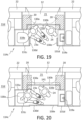
- FIG. 8 shows a fourth stage of a convertible monument deployment for a temporary and convertible aircraft cabin monument.
- monument wall section 30c is configured into the deployed position.
- Monument wall section 30d as shown in FIG. 8 , is moved from the stowed position to a deployed position through the use of a wall section folding mechanism 33a, 33c that can be, for example, a hinge.
- wall section 30e is moved from the stowed position to a deployed position through the use of a wall folding mechanism 33b, 33d that can be, for example, a hinge.
- a wall folding mechanism 33b, 33d that can be, for example, a hinge.
- deployed monument wall sections 30d and 30e form monument entry bi-fold doors (equivalently referred to herein as “monument doors”, “monument entry doors”, “monument entry sections”) that provide entryways, for example, into fully deployed monument compartments 116a, 116b (also referred to equivalently herein as "fully enclosed monument compartments” 116a, 116b, even though the door to be formed by deployed wall sections 30d and 30e may not be completely closed, as shown, for example, in FIG. 9 ).
- the remainder of the enumerated features shown in FIG. 8 are those shown in FIGs. 4, 5 , 6, and 7 .
- FIG. 9 shows the convertible aircraft cabin monument 114a as shown in FIG. 8 , with monument wall sections 30d, 30e in the deployed configuration and further moved into a closed position to form fully enclosed monument compartments 116a, 116b in convertible aircraft cabin monument 114a.
- the remainder of the enumerated features shown in FIG. 9 are those shown in FIGs. 4, 5 , 6, 7 , and 8 .
- the fully deployed monument wall sections and monument bi-fold doors border the enclosed monument compartments 116a, 116b that each house a urinal that can reside in the convertible monument, with the convertible monument having a convertible monument footprint that can be equivalent to or smaller than a monument footprint of a conventional single lavatory on an aircraft.
- the presently disclosed convertible monuments as shown in FIGs. 8, 9 , can house two compartments with each compartment housing a urinal, the passenger-to-lavatory ratio on an aircraft implementing the presently disclosed convertible monument can at least remain the same or, advantageously, can decrease. That is, the presently disclosed convertible monuments housing two lavatories can replace a conventional monument that may house one lavatory.
- FIGs. 10 and 11 are enlarged overhead views of the stowed sections 120a, 120b (as also shown in FIG. 4 ) of the convertible monument in the stowed configuration. More particularly, FIGs. 10 and 11 are an enlarged overhead views of a portion of a convertible monument showing wall sections in the stowed configuration, with certain monument features (e.g., monument features that can be fixed monument features), for example, including a urinal and a sink, enclosed or otherwise contained by a plurality of monument wall sections in the stowed monument wall configuration.
- certain monument features e.g., monument features that can be fixed monument features
- stowed section 120a includes urinal 18a and sink 19a that can be positioned in the stowed section 120a and that will be located in fully deployed compartment 116a of convertible aircraft cabin monument 114a in the deployed configuration.
- Urinal 18a and sink 19a can be fixed monument components that can be, for example, fixedly attached to structural components located within stowed section 120a.
- the monument wall sections in the stowed configuration are more clearly viewed in FIG. 10 . As shown in FIG.
- monument first compartment 116a can be a lavatory comprising a urinal.
- stowed section 120b includes urinal 18b and sink 19b that can be positioned in the stowed section 120b and that will be located in fully deployed compartment 116b of convertible aircraft cabin monument 114a in the deployed configuration.
- Urinal 18b and sink 19b can be fixed monument components that can be, for example, fixedly attached to structural components located within stowed section 120b.
- Wall section 30b is shown in FIG. 11 in the stowed configuration, with wall section 30b becoming a portion of the monument back wall 41 of convertible aircraft cabin monument 114a, when the wall sections are oriented into the deployed configuration.
- Monument first compartment 116b can be a lavatory comprising a urinal.
- FIG. 12 shows an overhead view of the monument components shown in FIG. 10 , with the wall moveable wall sections now in an unfolded and deployed configuration to form compartment 16a of convertible aircraft cabin monument 114a.
- wall sections 30c, 30c', 30d when foldable wall sections 30c, 30c', 30d are unfolded or deployed, wall sections 30c, 30c', 30d and a portion of wall section 30a (to which wall section 30c' is attached) together, in combination, form deployed monument inner wall 37 that can be a common monument inner or interior wall to fully deployed compartment 116a and fully deployed compartment 116b, for example, in convertible aircraft cabin monument 114a shown in the FIGs.
- the monument wall sections when oriented into a deployed configuration (e.g., when deployed from the stowed configuration) will form a common monument inner wall 37 (shown in FIG. 12 ) separating compartment 116a from compartment 116b (e.g., an inner wall that is "common" to compartment 116a and compartment 116b) in convertible aircraft cabin monument 114a shown in the deployed configuration.
- the monument wall sections 30c, 30c', 30d are in communication with or otherwise foldably attached to monument wall section 30a.
- the deployed wall section 30c, 30c', 30d forming a deployed monument inner common wall separating compartment 116a from compartment 116b (e.g., a single inner wall that is "common" to compartment 16a and compartment 16b) in convertible aircraft cabin monument 114a can be in communication with or otherwise foldably attached to monument wall section 30b.
- the inner wall section that separates compartment 116a from compartment 116b in convertible aircraft cabin monument 114a can be a "double wall” that comprises two immediately juxtaposed and overlapping (or substantially overlapping) inner wall sections with a first inner wall section or layer in communication with monument wall section 30a, and a second inner wall section or layer in communication with monument wall section 30b.
- the first and second inner wall sections can have thickness that can be less than the thicknesses of the other moveable wall sections and fixed wall sections, since the inner wall section in the deployed configuration will have two overlapping sections.
- the convertible aircraft cabin monuments can be formed from converting stowed monument wall sections to deployed monument wall sections, forming convertible aircraft cabin monuments that include a full lavatory with, for example, a toilet, sink, etc., with or without a urinal in one or more compartments of the deployed convertible aircraft cabin monument.
- FIGs. 13-21 show examples with a convertible aircraft cabin monument comprising appointments typically located in an aircraft lavatory (e.g., a toilet, a sink, etc.).
- FIGs. 13, 14 , 15 further illustrate apparatuses, systems, and methods relating to a temporary and convertible aircraft interior monument, including a monument that can be reversibly configured from a stowed configuration into a deployed monument configuration, on demand, manually or automatically.
- FIGs. 13, 14 , 15 illustrate a progression where monument wall components are moved from a stowed configuration to a deployed configuration to form a deployed monument (e.g., a deployed convertible temporary monument) that contains compartments that can function as lavatories.
- a deployed monument e.g., a deployed convertible temporary monument
- FIG. 13 is an overhead view of an aircraft interior 11d showing a person 23 (e.g., that can be a passenger, an attendant, etc.) standing in an aircraft cabin interior egress pathway 21, with attendant areas 20 shown adjacent the aircraft cabin interior egress pathway 21.
- FIG. 13 further shows an aircraft door 12 in the closed position, and outboard wall 22.
- certain monument components can be fixed monument components, that can include, for example, toilet 118a and sink 119a, are hidden from view in a stowed space 220a and 220b, respectively, by monument wall sections 130a, 130b, 130d, 130e, with the monument walls in a folded and stowed configuration.
- stowed monument wall sections enclose or otherwise contain the fixed monuments into a stowed section.
- FIG. 14 shows a first stage of a convertible monument deployment for a temporary monument.
- monument wall sections 130a and 130b are configured to be moved from a stowed configuration to a deployed position.
- Monument wall section 130a is moved from the stowed position to a deployed position through the use of a wall section folding mechanism 132a (shown in FIG. 15 ) that can be, for example, a hinge, with wall section folding mechanism 132a in communication with monument wall section 130a in further communication with fixed structure 131a.
- wall section 130b is moved from the stowed position to a deployed position through the use of a wall section folding mechanism 132b that can be, for example, a hinge, with folding mechanism 132b (shown in FIG. 15 ) in communication with monument wall section 130b in further communication with fixed structure 131b.
- the combined monument wall sections 130a, 130b in the deployed configuration form the monument back wall 141.
- FIG. 15 and FIG. 16 show a second stage of a convertible monument deployment for a temporary monument.
- monument wall section 130d as shown in FIGs. 15, 16 , is moved from the stowed position to a deployed position by using wall section folding mechanism 132d that can be, for example, a hinge.
- wall section 130e can be moved from the stowed position to a deployed position by using a wall section folding mechanism 132e that can be, for example, a hinge.
- convertible (and, e.g., temporary) aircraft cabin monument 114b is formed. As shown in FIG.
- deployed monument wall sections 130d and 130e form monument entry sections (equivalently referred to herein as "monument doors") that provide entryways, for example, into compartment 116a of the convertible aircraft cabin monument 114b.
- the remainder of the enumerated features shown in FIG. 15 are those shown in FIGs. 13 and 14 .
- FIG. 16 shows the convertible aircraft cabin monument 114b in the deployed configuration, as also shown in FIG. 15 , but with monument wall sections 130d, 130e in the deployed configuration and further moved into a closed position to form fully enclosed compartment 116a in convertible aircraft cabin monument 114b with monument door closed.
- the remainder of the enumerated features shown in FIG. 16 are those shown in FIGs. 13, 14 , and 15 .
- FIGs. 17, 18 are overhead views of a person 23 entering convertible aircraft cabin monument 114b via folding monument wall section 130e (with folding monument wall section configured into, for example, a door) for the purpose of occupying compartment 116a that has been fashioned into a convertible temporary lavatory.
- person 23 has closed folding monument wall section 130e (with folding monument wall section configured into, for example, a door) for privacy and is able to move comfortably within compartment 116a of convertible aircraft cabin monument 114b to use toilet 118a.
- the toilet 118a occupies a region of compartment 116a within convertible aircraft cabin monument 114b that allows ample shoulder width of a passenger to comfortably use toilet 118a.
- the compartments within the convertible aircraft cabin monument can be oriented into various configurations including, but not limited to configurations shown in the accompanying FIGs. such as, for example: first and second integrated lavatories; a single larger lavatory configured to accommodate, for example, persons having reduced mobility (PRM) lavatories; a "full" unisex lavatory comprising a toilet, and/or a lavatory comprising one or more urinals designed for use by biologically male-gendered passengers.
- first and second integrated lavatories such as, for example: first and second integrated lavatories; a single larger lavatory configured to accommodate, for example, persons having reduced mobility (PRM) lavatories; a "full" unisex lavatory comprising a toilet, and/or a lavatory comprising one or more urinals designed for use by biologically male-gendered passengers.
- PRM reduced mobility
- FIGs. 19, 20 illustrate an overhead view of a convertible temporary aircraft monument, where, the convertible monument can be appointed, dimensioned, and otherwise customized to facilitate use of the monuments as lavatories to accommodate persons of reduced mobility (PRM).
- PRM 23a is shown having gained access into compartment 116a of convertible aircraft cabin monument 114c that has been configured into a lavatory with a toilet. Additional space required by a PRM to enter a contained space such as, for example, a lavatory, is provided in convertible aircraft cabin monument 114c via opening both folding monument wall sections 130d and 130e, with the two folding monument wall sections functioning as a pair of adjacently positioned folding doors that open "away" from each other.
- PRM assistant 24 is shown having gained access into convertible aircraft cabin monument 114c with PRM as evidence of the considerable and relative amount of space present in compartment 116a of convertible aircraft cabin monument 114c.
- FIG. 20 shows the convertible aircraft cabin monument 114c shown in FIG. 19 with the PRM 23a having sufficient room in compartment 116a to maneuver onto toilet 118a alone or with the assistance of PRM assistant 24.
- the remainder of the enumerated features shown in FIG. 20 are those also shown in FIG. 19 .
- FIGs. illustrate examples of folding wall sections in a compacted, stowed state that maintain the contents (e.g., monument components) of the convertible aircraft cabin monument out of view in the stowed state.
- contents e.g., monument components
- stowed components of the convertible monument are kept completely clear of the aircraft cabin egress pathway, including attendant areas within the egress pathway.
- the stowed monument footprint does not encumber or overlap with any portion of: 1) the egress pathway area; or 2) the attendant area (a part of which can coincide with the aircraft cabin egress pathway area), and the convertible monument in the stowed state fully complies with regulatory demands as to maintaining the availability and clearance of an aircraft cabin egress pathway, for example, when the plane is not in flight.
- the conversion from the stowed state to the deployed state that establishes the creation of the constructed temporary convertible aircraft cabin monument occurs, as a plurality of folded wall sections are deployed (e.g., extended, etc.) from the stowed state (e.g., the stowed configuration of the convertible monument) such that the deployed wall sections establish a completed convertible monument having a convertible monument footprint, and with the convertible monument footprint impinging on or otherwise overlapping with at least a portion of the aircraft cabin egress pathway.
- the wall sections can be deployed from the stowed configuration via methods and using apparatuses in addition to those shown in and illustrated in the presently disclosed exemplary and non-limiting FIGs.
- the specific deployment mechanisms of the wall sections through, for example, unfolding mechanisms shown in the present FIGs. can be obviated by or can work in concert with additional deployment mechanisms and methods.
- the stowed monument wall sections can be deployed from a stowed configuration via "unfolding" folded monument wall sections from the stowed configuration, as described herein, by manually or mechanically applying the force required for such deployment. That is, when construction of the aircraft cabin convertible monument is regulatorily allowed and access to an aircraft door (and access to the immediately adjacent aircraft cabin egress pathway) no longer provides any useful function (e.g., after takeoff, during flight, etc.), a flight attendant trained in the deployment of the convertible monument can conveniently conduct the deployment manually, and on demand, with the understanding that the manual deployment can require a predetermined amount of force within a force range that is within a suitable range of force possessed by an average human.
- the monument wall sections can be in communication with the mechanical elements used to effect movement of the plurality of wall sections mechanically and automatically through the use of powered means including, for example, and without limitation, electrically driven motors, including motors coupled to mechanical devices configured to drive the monument wall sections from a stowed configuration to a deployed configuration and to construct and otherwise assemble the temporary convertible monument.
- powered means including, for example, and without limitation, electrically driven motors, including motors coupled to mechanical devices configured to drive the monument wall sections from a stowed configuration to a deployed configuration and to construct and otherwise assemble the temporary convertible monument.
- the automated deployment and stowing of the deployed convertible monument can further include various circuitry, wiring, control panels, controllers, signal transmitters, signal receivers, etc., with the automated systems able to be initiated, for example, through the use of wireless technologies, etc., and operated from a control panel that can be located proximate to sections of the stowed convertible monument having a dedicated control.
- the monument controls can further be integrated into a larger control panel configured to control functions in addition to the monument deployment (e.g. assembly) and stowage (e.g., disassembly).
- the controls can be located remotely from the monument, for example, with the monument controls located in another region of the aircraft (e.g., flight deck, galley, etc.).
- the controls if operated wirelessly, can be operated from a land-based or cloud-based solution including the use of, for example, the "internet of things", etc.
- the deployment and stowage of the convertible monuments can be controlled and effected according to predetermined timing relative to, for example, a flight itinerary, etc., with the convertible monument deployment and stowage occurring automatically upon, for example, manually inputted, or automated commands, etc.
- the deployment and stowage of convertible monument wall sections can comprise not only the deployment and stowage of folded monument wall sections, but also wall sections that may or may not fold, and can be automatically or manually deployed from cavities or compartments in aircraft floor assemblies, ceiling assemblies, etc., or monument wall sections can be "pocketed" monument wall sections that deploy from and that can be stowed into cavities or compartments within aircraft wall, wall assemblies, etc., including, for example, fixed wall assemblies having such cavities.
- FIGs. 21-24 are flowcharts outlining methods.
- FIG. 21 outlines a method 2300 for converting unused aircraft cabin space into a convertible aircraft cabin monument comprising providing 2302 a plurality of wall sections and moving 2304 the plurality of wall sections from a stowed wall section configuration into a deployed wall section configuration to form 2306 a plurality of deployed wall sections, and orienting 2308 the plurality of deployed wall sections to form a deployed monument, with the deployed monument comprising at least one enclosed compartment.
- the deployed monument comprises at least one lavatory, and the deployed monument further comprises a deployed monument footprint, with the method further including overlapping 2310 a portion of the aircraft cabin egress pathway with at least a portion of the deployed monument footprint, and wherein at least a portion of the aircraft cabin egress pathway is oriented adjacent an aircraft door.
- the deployed monument further includes at least one lavatory and the method further includes converting unused aircraft cabin space into a convertible aircraft cabin monument with the monument comprising at least one lavatory.
- Methods outlined in FIG. 21 can employ the monuments and monument components illustrated in one of more of FIGs. 4-20 .
- the deployed monument comprises at least one lavatory, and the deployed monument further comprises a deployed monument footprint, with the method further including overlapping 2310 a portion of the aircraft cabin egress pathway with at least a portion of the deployed monument footprint, and wherein at least a portion of the aircraft cabin egress pathway is oriented adjacent an aircraft door.
- the deployed monument further includes at least one lavatory and the method further includes converting unused aircraft cabin space into a convertible aircraft cabin monument with the monument comprising at least one lavatory, with the method further including converting 2402 unused aircraft cabin space into a convertible aircraft cabin monument.
- Methods outlined in FIG. 22 can employ the monuments and monument components illustrated in one of more of FIGs. 4-20
- the deployed monument comprises at least one lavatory, and the deployed monument further comprises a deployed monument footprint, with the method further including overlapping 2310 a portion of the aircraft cabin egress pathway with at least a portion of the deployed monument footprint, and wherein at least a portion of the aircraft cabin egress pathway is oriented adjacent an aircraft door.
- the deployed monument further includes at least one lavatory and the method further includes converting unused aircraft cabin space into a convertible aircraft cabin monument with the monument comprising at least one lavatory, with the method further including converting 2402 unused aircraft cabin space into a convertible aircraft cabin monument.
- Method 2500 further comprises expanding 2502 a plurality of wall sections from a stowed configuration to a deployed configuration to form the monument footprint.
- Methods outlined in FIG. 22 can employ the monuments and monument components illustrated in one of more of FIGs. 4-20 .
- FIG. 24 is a flowchart outlining a method 2600 for installing a convertible aircraft cabin monument with the method including providing 2602 a plurality of wall sections, moveably connecting 2604 at least two wall sections of the plurality of wall sections, forming 2606 a plurality of moveably connected wall sections, and securing 2608 at least a number greater than or equal to one of the plurality of moveably connected wall sections to a fixed structure.
- the plurality of moveably connected wall sections is configured to move from a stowed wall section configuration to a deployed wall section configuration, and with the with the plurality of moveably connected deployed wall sections in in the deployed wall section configuration forming an convertible aircraft cabin monument having a convertible aircraft cabin monument having a convertible aircraft cabin monument footprint.
- the convertible aircraft cabin monument footprint is configured to at least overlap a portion of the aircraft cabin egress pathway.
Landscapes
- Engineering & Computer Science (AREA)
- Aviation & Aerospace Engineering (AREA)
- Residential Or Office Buildings (AREA)
- Hydrogenated Pyridines (AREA)
Claims (15)
- Aéronef comprenant une cabine d'aéronef, dans lequel la cabine d'aéronef comprend :un couloir de sortie de la cabine d'aéronef orienté à proximité d'une porte de l'aéronef (12) ; etun module de cabine d'aéronef convertible (114a, 114b, 114c) comprenant :
une pluralité de sections de parois mobiles (30a, 30b, 30c, 30c', 30d, 30e) couplées à une pluralité de structures fixes (31a, 31b, 31c, 31d), la pluralité de sections de parois mobiles étant configurée pour passer d'une configuration de section de paroi rangée à une configuration de section de paroi déployée ; dans lequel :une première section de paroi mobile (30a) de la pluralité de sections de parois mobiles (30a, 30b, 30c, 30c', 30d, 30e) est configurée pour passer de la configuration rangée à la configuration déployée à l'aide d'un premier mécanisme de repliement de section de paroi (32a) ;une deuxième section de paroi mobile (30b) de la pluralité de sections de parois mobiles (30a, 30b, 30c, 30c', 30d, 30e) est configurée pour passer de la configuration rangée à la configuration déployée à l'aide d'un deuxième mécanisme de repliement de section de paroi (32b), dans lequel la première et la deuxième sections de parois mobiles combinées (30a, 30b) dans la configuration déployée forment une paroi arrière de module (141) ;une troisième section de paroi mobile (30d) de la pluralité de sections de parois mobiles (30a, 30b, 30c, 30c', 30d, 30e) est configurée pour passer de la configuration rangée à la configuration déployée à l'aide d'un troisième mécanisme de repliement de section de paroi (33a, 33c) ; etune quatrième section de paroi mobile (30e) de la pluralité de sections de parois mobiles (30a, 30b, 30c, 30c', 30d, 30e) est configurée pour passer de la configuration rangée à la configuration déployée à l'aide d'un quatrième mécanisme de repliement de section de paroi (33b, 33d), dans lequel la troisième section de paroi mobile (30d) et la quatrième section de paroi mobile (30e), lorsqu'elles se trouvent dans la configuration déployée, forment des portes de module qui permettent d'entrer dans un compartiment (116a, 116b) du module de cabine d'aéronef convertible (114a, 114b, 114c) ;et dans lequel :la pluralité de sections de parois mobiles dans la configuration de section de paroi déployée est configurée pour former le module de cabine d'aéronef convertible dans une configuration de module déployé ;le module de cabine d'aéronef convertible dans la configuration déployée comprend un encombrement de module déployé ; etl'encombrement de module déployé chevauche au moins une partie d'un couloir de sortie de cabine d'aéronef (21). - Aéronef selon la revendication 1, dans lequel l'encombrement de module déployé chevauche au moins une partie d'une zone de personnel de bord (20).
- Aéronef selon la revendication 1 ou 2, dans lequel le module de cabine d'aéronef convertible comprend un toilette qui, éventuellement, comprend un urinoir (18a, 18b).
- Aéronef selon l'une quelconque des revendications 1 à 3, dans lequel le module de cabine d'aéronef convertible comprend une pluralité de compartiments.
- Aéronef selon la revendication 4, dans lequel la pluralité de compartiments comprend un premier compartiment (116a) et un deuxième compartiment (116b) qui sont configurés pour se convertir en un seul compartiment.
- Aéronef selon la revendication 4 ou la revendication 5, dans lequel au moins deux de la pluralité de compartiments comprennent une paroi commune intérieure (37) .
- Aéronef selon l'une quelconque des revendications 4 à 6, dans lequel chacun de la pluralité de compartiments comprend un urinoir.
- Aéronef selon l'une quelconque des revendications 1 à 7, dans lequel la pluralité de sections de parois mobiles est configurée pour passer manuellement ou automatiquement, à la demande, de la configuration de section de paroi rangée à la configuration de section de paroi déployée.
- Aéronef selon l'une quelconque des revendications 1 à 8, dans lequel au moins deux de la pluralité de sections de parois mobiles sont configurées pour être fixées sur une structure fixe.
- Procédé (2300, 2400, 2500) destiné à convertir un espace de cabine d'aéronef inutilisé en un module de cabine d'aéronef convertible, le procédé comprenant :
le déplacement (2304) d'une pluralité de sections de parois mobiles, couplées à une pluralité de structures fixes (31a, 31b, 31c, 31d), d'une configuration de sections de parois rangées à une configuration de sections de parois déployées afin de former une pluralité de sections de parois déployées, dans lequel :une première section de paroi mobile (30a) de la pluralité de sections de parois mobiles (30a, 30b, 30c, 30c', 30d, 30e) est déplacée de la configuration rangée à la configuration déployée à l'aide d'un premier mécanisme de repliement de section de paroi (32a) ;une deuxième section de paroi mobile (30b) de la pluralité de sections de parois mobiles (30a, 30b, 30c, 30c', 30d, 30e) est déplacée de la configuration rangée à la configuration déployée à l'aide d'un deuxième mécanisme de repliement de section de paroi (32b), dans lequel la première et la deuxième sections de parois mobiles combinées (30a, 30b) dans la configuration déployée forment une paroi arrière de module (141) ;une troisième section de paroi mobile (30d) de la pluralité de sections de parois mobiles (30a, 30b, 30c, 30c', 30d, 30e) est déplacée de la configuration rangée à la configuration déployée à l'aide d'un troisième mécanisme de repliement de section de paroi (33a, 33c) ;une quatrième section de paroi mobile (30e) de la pluralité de sections de parois mobiles (30a, 30b, 30c, 30c', 30d, 30e) est déplacée de la configuration rangée à la configuration déployée à l'aide d'un quatrième mécanisme de repliement de section de paroi (33b, 33d), dans lequel la troisième section de paroi mobile (30d) et la quatrième section de paroi mobile (30e), lorsqu'elles se trouvent dans la configuration déployée, forment des portes de module qui permettent d'entrer dans un compartiment (116a, 116b) du module de cabine d'aéronef convertible (114a, 114b, 114c) ;l'orientation (2306, 2308) de la pluralité de sections de parois déployées afin de former un module déployé dans une configuration de module déployé, le module déployé comprenant un encombrement de module déployé, le module déployé comprenant en outre au moins un toilette ;le chevauchement (2310) d'au moins une partie d'un couloir de sortie de cabine d'aéronef avec au moins une partie de l'encombrement de module déployé, l'au moins une partie du couloir de sortie de cabine d'aéronef étant orientée de manière adjacente à une porte de l'aéronef ; etla conversion (2402) d'un espace de cabine d'aéronef inutilisé en un module de cabine d'aéronef convertible, le module de cabine d'aéronef convertible comprenant un encombrement de module de cabine d'aéronef convertible. - Procédé selon la revendication 10, comprenant en outre :
l'extension (2502) de la pluralité de sections de parois de la configuration de sections de parois rangées à la configuration de sections de parois déployées afin de former le module déployé dans la configuration de module déployé, le module déployé comprenant l'encombrement de module déployé. - Procédé selon la revendication 10 ou 11, comprenant en outre :l'extension (2502) de la pluralité de sections de parois depuis la configuration de sections de parois rangées par au moins l'un : du déploiement de la pluralité de sections de parois ; de l'enroulement de la pluralité de sections de parois ; et du coulissement de la pluralité de sections de parois ; et/oula jonction de la pluralité de sections de parois déployées dans un état engagé.
- Procédé selon l'une quelconque des revendications 10 à 12, comprenant en outre :
la conversion (2402) du module de cabine d'aéronef convertible de la configuration de module déployé à une configuration de module rangé. - Procédé selon l'une quelconque des revendications 10 à 13, dans lequel les sections de parois déployées sont reliées de manière mobile.
- Procédé selon l'une quelconque des revendications 10 à 14, comprenant en outre : la jonction de la pluralité de sections de parois déployées dans un état engagé.
Applications Claiming Priority (2)
| Application Number | Priority Date | Filing Date | Title |
|---|---|---|---|
| US202063122103P | 2020-12-07 | 2020-12-07 | |
| US17/499,196 US12258127B2 (en) | 2020-12-07 | 2021-10-12 | Convertible aircraft cabin monument |
Publications (2)
| Publication Number | Publication Date |
|---|---|
| EP4008635A1 EP4008635A1 (fr) | 2022-06-08 |
| EP4008635B1 true EP4008635B1 (fr) | 2025-04-30 |
Family
ID=78821026
Family Applications (1)
| Application Number | Title | Priority Date | Filing Date |
|---|---|---|---|
| EP21212230.3A Active EP4008635B1 (fr) | 2020-12-07 | 2021-12-03 | Monument convertible de cabine d'aéronef |
Country Status (2)
| Country | Link |
|---|---|
| US (1) | US12258127B2 (fr) |
| EP (1) | EP4008635B1 (fr) |
Families Citing this family (10)
| Publication number | Priority date | Publication date | Assignee | Title |
|---|---|---|---|---|
| US11958609B2 (en) * | 2022-05-04 | 2024-04-16 | The Boeing Company | Expandable aircraft lavatory apparatus, system, and method |
| US12269595B2 (en) * | 2023-05-10 | 2025-04-08 | B/E Aerospace, Inc. | Wheelchair accessible airliner lavatory |
| US20250002153A1 (en) * | 2023-06-29 | 2025-01-02 | B/E Aerospace, Inc. | Premium and accessible lavatory with increased door opening |
| US20250121954A1 (en) * | 2023-10-11 | 2025-04-17 | The Boeing Company | Translating Barrier for an Aircraft |
| US12522357B2 (en) * | 2024-01-03 | 2026-01-13 | B/E Aerospace, Inc. | Large aircraft lavatory with storage compartments |
| EP4644244A1 (fr) * | 2024-04-29 | 2025-11-05 | AIRBUS Operations GmbH | Agencement de toilettes pour cabine d'aéronef |
| US12325522B1 (en) | 2024-05-03 | 2025-06-10 | B/E Aerospace, Inc. | Movable wall section for reduced mobility passenger access |
| DE102024121969A1 (de) * | 2024-08-01 | 2026-02-05 | Airbus Operations Gmbh | Waschraum zur Benutzung durch Personen mit eingeschränkter Mobilität |
| DE102024130337A1 (de) * | 2024-10-18 | 2026-04-23 | Diehl Aviation Hamburg Gmbh | Bordtoilette mit externen Funktionselementen |
| US12522358B1 (en) * | 2024-10-25 | 2026-01-13 | The Boeing Company | Convertible lavatory system for an internal cabin of an aircraft |
Citations (1)
| Publication number | Priority date | Publication date | Assignee | Title |
|---|---|---|---|---|
| US20190337623A1 (en) * | 2018-04-10 | 2019-11-07 | Rockwell Collins, Inc. | Self-Deploying Counter for Multimode Transformable Monuments |
Family Cites Families (26)
| Publication number | Priority date | Publication date | Assignee | Title |
|---|---|---|---|---|
| US6079669A (en) * | 1997-03-24 | 2000-06-27 | The Boeing Company | Dual pivot expandable lavatory |
| JP3573707B2 (ja) * | 2000-11-22 | 2004-10-06 | 株式会社ジャムコ | 航空機用拡張式ラバトリーユニット |
| DE102011013049A1 (de) * | 2011-03-04 | 2012-09-06 | Airbus Operations Gmbh | Flugzeugbereich |
| US20130206907A1 (en) * | 2012-02-14 | 2013-08-15 | C&D Zodiac, Inc. | Expandable lavatory with movable wall |
| US9045230B2 (en) * | 2012-02-14 | 2015-06-02 | C&D Zodiac, Inc. | Lavatory Monument Assembly |
| US20140291446A1 (en) * | 2012-11-05 | 2014-10-02 | C&D Zodiac, Inc. | Lavatory monument with storage compartment |
| US9045231B2 (en) * | 2012-11-05 | 2015-06-02 | C&D Zodiac, Inc. | Wheelchair accessible lavatory |
| US20150360782A1 (en) | 2013-02-13 | 2015-12-17 | Sell Gmbh | Aircraft |
| DE102013008291A1 (de) | 2013-05-15 | 2014-11-20 | Airbus Operations Gmbh | Erweiterbares Flugzeugmonument |
| DE102013008309A1 (de) * | 2013-05-15 | 2014-11-20 | Airbus Operations Gmbh | Modifizierbares Flugzeugmonument |
| US8944377B2 (en) * | 2013-06-11 | 2015-02-03 | The Boeing Company | Lavatory reconfiguration system |
| EP2873616B1 (fr) * | 2013-11-15 | 2019-10-30 | Airbus Operations GmbH | Agencement de toilette pour véhicule |
| FR3036098B1 (fr) * | 2015-05-12 | 2017-05-12 | Airbus Operations Sas | Dispositif d'acces a paroi pliante permettant la communication securisee entre au moins deux zones d'une enceinte |
| US20180251222A1 (en) * | 2017-03-01 | 2018-09-06 | B/E Aerospace, Inc. | Aircraft Lavatory Complex for People of Reduced Mobility |
| CA3090164A1 (fr) * | 2018-02-08 | 2019-08-15 | Dubai Aviation Engineering Projects | Module d'habitacle |
| WO2019213136A1 (fr) * | 2018-05-02 | 2019-11-07 | B/E Aerospace, Inc. | Toilettes modulaires accessibles aux passagers à mobilité réduite (pmr) |
| US11130575B2 (en) * | 2019-05-10 | 2021-09-28 | B/E Aerospace, Inc. | Slim aircraft monument with deployable workstation |
| EP3741676B1 (fr) * | 2019-05-23 | 2021-12-08 | Rockwell Collins, Inc. | Monument transformable multimodes |
| SG10201908047PA (en) * | 2019-08-30 | 2021-03-30 | St Eng Aerospace Ltd | Accessible Aircraft Lavatory |
| US11643210B2 (en) * | 2020-03-27 | 2023-05-09 | B/E Aerospace, Inc. | Flexible bar and shop space for aircraft cabin |
| US11572170B2 (en) * | 2020-07-21 | 2023-02-07 | B/E Aerospace, Inc. | Aircraft interior structure including actuatable panels and a footwell |
| US11618570B2 (en) * | 2020-12-07 | 2023-04-04 | The Boeing Company | Integral combined monuments in aircraft cabin interiors |
| US11884401B2 (en) * | 2021-01-02 | 2024-01-30 | The Boeing Company | Lavatory systems having containment compartments |
| US12065245B2 (en) * | 2021-01-05 | 2024-08-20 | The Boeing Company | Lavatory with expandable door |
| US12214884B2 (en) * | 2021-10-01 | 2025-02-04 | B/E Aerospace, Inc. | Expandable lavatory and cabin configuration including dedicated seating area and expandable lavatory |
| US11958609B2 (en) * | 2022-05-04 | 2024-04-16 | The Boeing Company | Expandable aircraft lavatory apparatus, system, and method |
-
2021
- 2021-10-12 US US17/499,196 patent/US12258127B2/en active Active
- 2021-12-03 EP EP21212230.3A patent/EP4008635B1/fr active Active
Patent Citations (1)
| Publication number | Priority date | Publication date | Assignee | Title |
|---|---|---|---|---|
| US20190337623A1 (en) * | 2018-04-10 | 2019-11-07 | Rockwell Collins, Inc. | Self-Deploying Counter for Multimode Transformable Monuments |
Also Published As
| Publication number | Publication date |
|---|---|
| US20220177136A1 (en) | 2022-06-09 |
| US12258127B2 (en) | 2025-03-25 |
| EP4008635A1 (fr) | 2022-06-08 |
Similar Documents
| Publication | Publication Date | Title |
|---|---|---|
| EP4008635B1 (fr) | Monument convertible de cabine d'aéronef | |
| US8534602B2 (en) | Residence and sleeping module with a connectable partial module for accomodating at least one member of and aircraft crew | |
| EP3608226B1 (fr) | Agencement de toilette pour véhicule | |
| EP2815974B1 (fr) | Système de reconfiguration de toilettes | |
| EP2803578B1 (fr) | Monument d'aéronef extensible | |
| EP3947148B1 (fr) | Bloc toilettes d'aéronef accessible aux pmr | |
| US9457903B2 (en) | Modifiable aircraft monument | |
| US8740143B2 (en) | Compartment for accommodating at least one flight crewmember | |
| US20130206907A1 (en) | Expandable lavatory with movable wall | |
| US7942367B2 (en) | Rest compartment for an aircraft pilot | |
| US11958609B2 (en) | Expandable aircraft lavatory apparatus, system, and method | |
| US7389959B2 (en) | Modular overhead privacy system and method | |
| US11618570B2 (en) | Integral combined monuments in aircraft cabin interiors | |
| EP4159624B1 (fr) | Configuration de toilettes et de cabine extensibles comprenant une zone de siège dédiée et toilettes extensibles | |
| EP3263444B1 (fr) | Module de cabine et agencement pour un aéronef de passagers | |
| EP4098564B1 (fr) | Systèmes de zone de repos pour cabine interne d'un véhicule | |
| US12612161B2 (en) | Transforming lavatory door | |
| EP4582341A1 (fr) | Toilettes pour avions | |
| EP4484276A1 (fr) | Toilettes à qualité supérieure et accessibles avec ouverture de porte accrue | |
| HK40002781A (en) | Cabin module and layout for a passenger aircraft |
Legal Events
| Date | Code | Title | Description |
|---|---|---|---|
| PUAI | Public reference made under article 153(3) epc to a published international application that has entered the european phase |
Free format text: ORIGINAL CODE: 0009012 |
|
| STAA | Information on the status of an ep patent application or granted ep patent |
Free format text: STATUS: THE APPLICATION HAS BEEN PUBLISHED |
|
| AK | Designated contracting states |
Kind code of ref document: A1 Designated state(s): AL AT BE BG CH CY CZ DE DK EE ES FI FR GB GR HR HU IE IS IT LI LT LU LV MC MK MT NL NO PL PT RO RS SE SI SK SM TR |
|
| STAA | Information on the status of an ep patent application or granted ep patent |
Free format text: STATUS: REQUEST FOR EXAMINATION WAS MADE |
|
| 17P | Request for examination filed |
Effective date: 20221207 |
|
| RBV | Designated contracting states (corrected) |
Designated state(s): AL AT BE BG CH CY CZ DE DK EE ES FI FR GB GR HR HU IE IS IT LI LT LU LV MC MK MT NL NO PL PT RO RS SE SI SK SM TR |
|
| RAP3 | Party data changed (applicant data changed or rights of an application transferred) |
Owner name: THE BOEING COMPANY |
|
| STAA | Information on the status of an ep patent application or granted ep patent |
Free format text: STATUS: EXAMINATION IS IN PROGRESS |
|
| 17Q | First examination report despatched |
Effective date: 20231206 |
|
| GRAP | Despatch of communication of intention to grant a patent |
Free format text: ORIGINAL CODE: EPIDOSNIGR1 |
|
| STAA | Information on the status of an ep patent application or granted ep patent |
Free format text: STATUS: GRANT OF PATENT IS INTENDED |
|
| INTG | Intention to grant announced |
Effective date: 20241210 |
|
| P01 | Opt-out of the competence of the unified patent court (upc) registered |
Free format text: CASE NUMBER: APP_251/2025 Effective date: 20250103 |
|
| GRAS | Grant fee paid |
Free format text: ORIGINAL CODE: EPIDOSNIGR3 |
|
| GRAA | (expected) grant |
Free format text: ORIGINAL CODE: 0009210 |
|
| STAA | Information on the status of an ep patent application or granted ep patent |
Free format text: STATUS: THE PATENT HAS BEEN GRANTED |
|
| AK | Designated contracting states |
Kind code of ref document: B1 Designated state(s): AL AT BE BG CH CY CZ DE DK EE ES FI FR GB GR HR HU IE IS IT LI LT LU LV MC MK MT NL NO PL PT RO RS SE SI SK SM TR |
|
| REG | Reference to a national code |
Ref country code: CH Ref legal event code: EP Ref country code: GB Ref legal event code: FG4D |
|
| REG | Reference to a national code |
Ref country code: IE Ref legal event code: FG4D |
|
| REG | Reference to a national code |
Ref country code: DE Ref legal event code: R096 Ref document number: 602021029936 Country of ref document: DE |
|
| REG | Reference to a national code |
Ref country code: NL Ref legal event code: MP Effective date: 20250430 |
|
| REG | Reference to a national code |
Ref country code: AT Ref legal event code: MK05 Ref document number: 1789850 Country of ref document: AT Kind code of ref document: T Effective date: 20250430 |
|
| PG25 | Lapsed in a contracting state [announced via postgrant information from national office to epo] |
Ref country code: ES Free format text: LAPSE BECAUSE OF FAILURE TO SUBMIT A TRANSLATION OF THE DESCRIPTION OR TO PAY THE FEE WITHIN THE PRESCRIBED TIME-LIMIT Effective date: 20250430 Ref country code: PT Free format text: LAPSE BECAUSE OF FAILURE TO SUBMIT A TRANSLATION OF THE DESCRIPTION OR TO PAY THE FEE WITHIN THE PRESCRIBED TIME-LIMIT Effective date: 20250901 Ref country code: FI Free format text: LAPSE BECAUSE OF FAILURE TO SUBMIT A TRANSLATION OF THE DESCRIPTION OR TO PAY THE FEE WITHIN THE PRESCRIBED TIME-LIMIT Effective date: 20250430 |
|
| REG | Reference to a national code |
Ref country code: LT Ref legal event code: MG9D |
|
| PG25 | Lapsed in a contracting state [announced via postgrant information from national office to epo] |
Ref country code: GR Free format text: LAPSE BECAUSE OF FAILURE TO SUBMIT A TRANSLATION OF THE DESCRIPTION OR TO PAY THE FEE WITHIN THE PRESCRIBED TIME-LIMIT Effective date: 20250731 Ref country code: NO Free format text: LAPSE BECAUSE OF FAILURE TO SUBMIT A TRANSLATION OF THE DESCRIPTION OR TO PAY THE FEE WITHIN THE PRESCRIBED TIME-LIMIT Effective date: 20250730 |
|
| PG25 | Lapsed in a contracting state [announced via postgrant information from national office to epo] |
Ref country code: NL Free format text: LAPSE BECAUSE OF FAILURE TO SUBMIT A TRANSLATION OF THE DESCRIPTION OR TO PAY THE FEE WITHIN THE PRESCRIBED TIME-LIMIT Effective date: 20250430 Ref country code: PL Free format text: LAPSE BECAUSE OF FAILURE TO SUBMIT A TRANSLATION OF THE DESCRIPTION OR TO PAY THE FEE WITHIN THE PRESCRIBED TIME-LIMIT Effective date: 20250430 |
|
| PG25 | Lapsed in a contracting state [announced via postgrant information from national office to epo] |
Ref country code: BG Free format text: LAPSE BECAUSE OF FAILURE TO SUBMIT A TRANSLATION OF THE DESCRIPTION OR TO PAY THE FEE WITHIN THE PRESCRIBED TIME-LIMIT Effective date: 20250430 |
|
| PG25 | Lapsed in a contracting state [announced via postgrant information from national office to epo] |
Ref country code: HR Free format text: LAPSE BECAUSE OF FAILURE TO SUBMIT A TRANSLATION OF THE DESCRIPTION OR TO PAY THE FEE WITHIN THE PRESCRIBED TIME-LIMIT Effective date: 20250430 |
|
| PG25 | Lapsed in a contracting state [announced via postgrant information from national office to epo] |
Ref country code: AT Free format text: LAPSE BECAUSE OF FAILURE TO SUBMIT A TRANSLATION OF THE DESCRIPTION OR TO PAY THE FEE WITHIN THE PRESCRIBED TIME-LIMIT Effective date: 20250430 |
|
| PG25 | Lapsed in a contracting state [announced via postgrant information from national office to epo] |
Ref country code: RS Free format text: LAPSE BECAUSE OF FAILURE TO SUBMIT A TRANSLATION OF THE DESCRIPTION OR TO PAY THE FEE WITHIN THE PRESCRIBED TIME-LIMIT Effective date: 20250731 |
|
| PG25 | Lapsed in a contracting state [announced via postgrant information from national office to epo] |
Ref country code: IS Free format text: LAPSE BECAUSE OF FAILURE TO SUBMIT A TRANSLATION OF THE DESCRIPTION OR TO PAY THE FEE WITHIN THE PRESCRIBED TIME-LIMIT Effective date: 20250830 |
|
| PG25 | Lapsed in a contracting state [announced via postgrant information from national office to epo] |
Ref country code: LV Free format text: LAPSE BECAUSE OF FAILURE TO SUBMIT A TRANSLATION OF THE DESCRIPTION OR TO PAY THE FEE WITHIN THE PRESCRIBED TIME-LIMIT Effective date: 20250430 |
|
| PGFP | Annual fee paid to national office [announced via postgrant information from national office to epo] |
Ref country code: GB Payment date: 20251229 Year of fee payment: 5 |
|
| PG25 | Lapsed in a contracting state [announced via postgrant information from national office to epo] |
Ref country code: SM Free format text: LAPSE BECAUSE OF FAILURE TO SUBMIT A TRANSLATION OF THE DESCRIPTION OR TO PAY THE FEE WITHIN THE PRESCRIBED TIME-LIMIT Effective date: 20250430 Ref country code: DK Free format text: LAPSE BECAUSE OF FAILURE TO SUBMIT A TRANSLATION OF THE DESCRIPTION OR TO PAY THE FEE WITHIN THE PRESCRIBED TIME-LIMIT Effective date: 20250430 |
|
| PGFP | Annual fee paid to national office [announced via postgrant information from national office to epo] |
Ref country code: FR Payment date: 20251226 Year of fee payment: 5 |
|
| PG25 | Lapsed in a contracting state [announced via postgrant information from national office to epo] |
Ref country code: CZ Free format text: LAPSE BECAUSE OF FAILURE TO SUBMIT A TRANSLATION OF THE DESCRIPTION OR TO PAY THE FEE WITHIN THE PRESCRIBED TIME-LIMIT Effective date: 20250430 |
|
| PG25 | Lapsed in a contracting state [announced via postgrant information from national office to epo] |
Ref country code: EE Free format text: LAPSE BECAUSE OF FAILURE TO SUBMIT A TRANSLATION OF THE DESCRIPTION OR TO PAY THE FEE WITHIN THE PRESCRIBED TIME-LIMIT Effective date: 20250430 |
|
| PG25 | Lapsed in a contracting state [announced via postgrant information from national office to epo] |
Ref country code: SK Free format text: LAPSE BECAUSE OF FAILURE TO SUBMIT A TRANSLATION OF THE DESCRIPTION OR TO PAY THE FEE WITHIN THE PRESCRIBED TIME-LIMIT Effective date: 20250430 Ref country code: RO Free format text: LAPSE BECAUSE OF FAILURE TO SUBMIT A TRANSLATION OF THE DESCRIPTION OR TO PAY THE FEE WITHIN THE PRESCRIBED TIME-LIMIT Effective date: 20250430 |
|
| PG25 | Lapsed in a contracting state [announced via postgrant information from national office to epo] |
Ref country code: IT Free format text: LAPSE BECAUSE OF FAILURE TO SUBMIT A TRANSLATION OF THE DESCRIPTION OR TO PAY THE FEE WITHIN THE PRESCRIBED TIME-LIMIT Effective date: 20250430 |
|
| REG | Reference to a national code |
Ref country code: DE Ref legal event code: R097 Ref document number: 602021029936 Country of ref document: DE |
|
| PLBE | No opposition filed within time limit |
Free format text: ORIGINAL CODE: 0009261 |
|
| STAA | Information on the status of an ep patent application or granted ep patent |
Free format text: STATUS: NO OPPOSITION FILED WITHIN TIME LIMIT |
|
| REG | Reference to a national code |
Ref country code: CH Ref legal event code: L10 Free format text: ST27 STATUS EVENT CODE: U-0-0-L10-L00 (AS PROVIDED BY THE NATIONAL OFFICE) Effective date: 20260311 |
|
| 26N | No opposition filed |
Effective date: 20260202 |
|
| PGFP | Annual fee paid to national office [announced via postgrant information from national office to epo] |
Ref country code: DE Payment date: 20251229 Year of fee payment: 5 |