EP4008652A1 - Müllbehälter - Google Patents
Müllbehälter Download PDFInfo
- Publication number
- EP4008652A1 EP4008652A1 EP21163805.1A EP21163805A EP4008652A1 EP 4008652 A1 EP4008652 A1 EP 4008652A1 EP 21163805 A EP21163805 A EP 21163805A EP 4008652 A1 EP4008652 A1 EP 4008652A1
- Authority
- EP
- European Patent Office
- Prior art keywords
- container
- base
- cover
- frame element
- pins
- Prior art date
- Legal status (The legal status is an assumption and is not a legal conclusion. Google has not performed a legal analysis and makes no representation as to the accuracy of the status listed.)
- Withdrawn
Links
- 239000002699 waste material Substances 0.000 claims abstract description 32
- 239000004744 fabric Substances 0.000 claims abstract description 10
- 239000000463 material Substances 0.000 abstract description 2
- 230000004069 differentiation Effects 0.000 description 1
- 239000010815 organic waste Substances 0.000 description 1
Images


Classifications
-
- B—PERFORMING OPERATIONS; TRANSPORTING
- B65—CONVEYING; PACKING; STORING; HANDLING THIN OR FILAMENTARY MATERIAL
- B65F—GATHERING OR REMOVAL OF DOMESTIC OR LIKE REFUSE
- B65F1/00—Refuse receptacles; Accessories therefor
- B65F1/14—Other constructional features; Accessories
- B65F1/1468—Means for facilitating the transport of the receptacle, e.g. wheels, rolls
-
- B—PERFORMING OPERATIONS; TRANSPORTING
- B65—CONVEYING; PACKING; STORING; HANDLING THIN OR FILAMENTARY MATERIAL
- B65F—GATHERING OR REMOVAL OF DOMESTIC OR LIKE REFUSE
- B65F1/00—Refuse receptacles; Accessories therefor
- B65F1/14—Other constructional features; Accessories
- B65F1/141—Supports, racks, stands, posts or the like for holding refuse receptacles
- B65F1/1415—Supports, racks, stands, posts or the like for holding refuse receptacles for flexible receptables, e.g. bags, sacks
-
- B—PERFORMING OPERATIONS; TRANSPORTING
- B65—CONVEYING; PACKING; STORING; HANDLING THIN OR FILAMENTARY MATERIAL
- B65F—GATHERING OR REMOVAL OF DOMESTIC OR LIKE REFUSE
- B65F2220/00—Properties of refuse receptacles
- B65F2220/106—Collapsible
Definitions
- the present invention relates to a waste container.
- This waste container is used in the field of camping or home accessories.
- Removable container devices are known in the art, namely removable waste bins for separate waste collection are known.
- EP18425086A1 also discloses a travel device for separate waste collection comprising a circular base, a series of rods with threaded ends that can be connected together to compose support bars, at least two circular sections designed to be attached to the support bars, and a circular cover designed to cover the separate waste collection device at its top.
- This travel device for separate waste collection also comprises a band of flexible fabric, which is designed to be attached to the circular base and the circular sections to form a cylinder.
- the aforementioned parts are configured to be separated and stored in a small space, possibly for transportation.
- the technical purpose of the present invention is to provide a waste container that can obviate the aforementioned prior art drawbacks.
- the waste container of the present invention is configured to be converted between a collection configuration, in which the container is configured to collect waste in several compartments, and a transport configuration, in which the container contains all its constituting parts and can be stored in a smaller and easily moved compartment.
- Such waste container comprises a base that can be laid on a surface, and a plurality of pins having a main direction of extension and adapted to be fixed to the base such that the main direction of extension of each pin will be oriented perpendicular to the base.
- the container further comprises at least one frame element having a plurality of holes corresponding to the pins and a closing cover.
- the holes of the frame element shall be simply slid onto the corresponding pins until the frame element rests on the base, so that, by connecting the cover to the pins, the frame element will be locked between the base and the cover.
- the present invention relates to a waste container 1, in particular of the type that can be converted for easy transport or storage when not in use.
- the container 1 is adapted to be converted between a collection configuration in which it is configured to collect waste and a transport configuration in which it is configured to be easily moved. Further details about the collection and transport configurations will be provided hereinbelow.
- This container 1 comprises a base 2 configured to be laid on a surface, such as a floor or a field.
- the base 2 is substantially flat and is delimited by a rectangular perimeter edge 20.
- the perimeter edge 20 may have any geometric shape.
- the base 2 comprises a plurality of support means 21 made of a plastic or rubber material and configured to contact such surface.
- the base 2 comprises a plurality of housings 22 distributed close to the perimeter edge 20.
- the perimeter edge 20 is a regular polygon and the housings 22 are arranged at each vertex of the perimeter edge 20.
- the container 1 comprises a plurality of pins 3 having a main direction of extension X-X.
- these pins 3 are adapted to be fixed to the base 2 such that the main direction of extension X-X of each pin 3 is oriented perpendicular to the base 2.
- each pin 3 is configured to be fixed in a relative housing 22 of the base 2, so that its mail direction of extension X-X will be perpendicular to the base 2.
- the pins 3 can be formed integrally with the base 2, i.e. of one piece with the base 2.
- Such pins 3 are fixed to the base 2 when the container is in the transport configuration.
- the container 1 further comprises at least one frame element 4 having a central opening 42, as shown in Figure 4 .
- the container comprises two geometrically identical frame elements 4.
- Such frame element 4 comprises a plurality of through holes 41 for receiving respective pins 3 therein. More in detail, each pin 3 is configured to fit into a respective hole 41 in its respective main direction of X-X, to move the frame element to abutment against the base 2 along the pins 3, when the container 1 is in the transport configuration.
- the pins 3 fit in respective holes 41 of the frame element 4 when the container 1 is in the transport configuration.
- the frame element 4 is substantially flat and is delimited by a rectangular perimeter edge 40.
- the perimeter edge 40 may have any geometric shape.
- the perimeter edge 40 of the frame element 4 is a regular polygon and the holes 41 are located at each vertex of the perimeter edge 20. Even more preferably, the perimeter edges 20, 40 of the base and of the frame element are identical, and can be perfectly aligned, as shown in Figure 1 .
- the perimeter edge 40 of the frame element 4 has a plurality of channels 44 for receiving respective handles 81 of a bag-holding element 8, without projections from the frame element 4. Further details about the handles 81 and the bag-holding element 8 will be provided hereinbelow.
- the pins 3 fixed to the base 2, when fitted in the respective holes 41, are configured to lock the relative position of the frame element 4 with respect to the base 2.
- the pins 3 are configured to align the perimeter edges 20, 40 of the base 2 and of the frame element 4, when the container 1 is in the transport configuration as shown in Figure 1 .
- the container 1 further comprises a cover 5 for closing the container 1 at its top.
- the cover 5 comprises holding means 51 that can be grasped by a user to move the container 1 in the transport configuration, and to lift the cover 5 in the collection configuration.
- the cover 5 is configured to be connected to the pins 3.
- the cover 5 comprises a plurality of holes 52 adapted to receive respective pins 3 for connecting the cover 5 to the pins 3 by means of a closure element 6 in the transport configuration.
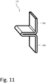
- the cover 5 is connected to the frame element 4 via at least one hinge 10 when the container 1 is in the collection configuration.
- the hinge 10 comprises a first wall 10a fixed to the cover 5 and a second wall 10b fixed to the frame element 4, when the container 1 is in the collection configuration.
- the first and second walls 10a, 10b of the hinge 10 are configured to pivot relative to each other to move the cover 5 relative to the frame element 4, and to open/close the container 1 at its top when it is in the collection configuration.
- the cover 5 is substantially flat and is delimited by a rectangular perimeter edge 50.
- the perimeter edge 50 may have any geometric shape.
- the perimeter edge 50 of the cover 5 is a regular polygon and the holes 52 are located at each vertex of the perimeter edge 50.
- the perimeter edges 20, 40, 50 of the base, of the frame element and of the cover are identical, and can be placed perfectly one on top of the other, as shown in Figure 1 .
- the frame element 4 is locked between the base 2 and the cover 5 when the container 1 is in the transport configuration. Therefore, in the transport configuration, the perimeter edge 40 of the frame element 4 is interposed between the perimeter edges 20, 50 of the base 2 and of the cover 5.
- the pins 3, when fitted in the respective holes 52 of the cover, are configured to lock the relative position of the cover 5 with respect to the base 2.
- the pins 3 are configured to align the perimeter edges 20, 40, 50 of the base 2, of the frame element 4 and of the cover 5 when the container 1 is in the transport configuration , as shown in Figure 1 .
- the container 1 of the present invention further comprises a plurality of closure elements 6.
- Such closure element 6 is configured to be attached to a respective pin 3 to keep the frame element 4 locked between the base 2 and the cover 5 in the transport configuration, as shown in Figure 1 .
- each closure element 6 mainly extends along a longitudinal direction Y-Y between first and second ends 63, 64.
- Each closure element 6 comprises anchor means 60 at the second end 64 and adapted to attach each closure element 6 to its pin 3.
- anchor means 60 shall be intended to mean to one or more mechanical connection elements which are adapted to constrain the relative movement between two parts, such as a threaded connection.
- each closure element 6 comprises a contact surface 61 located at the first end 63 and extending transverse, preferably perpendicular, to the longitudinal direction Y-Y. This contact surface 61 is configured to abut the cover 5 when the closure element 6 is attached to its pin 3 and when the container 1 is in the transport configuration.
- Each closure element 6 is connected to its pin 3 by means of the anchor elements 60, so that the contact surfaces 61 that abut the cover 5 lock the frame element 4 between the base 2 and the cover 5 when the container 1 is in the transport configuration.
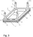
- the container 1 further comprises a plurality of rods 7 which are configured to be connected at least in pairs to form a support element 70, as shown in Figure 7 .
- Each rod 7 is specially configured to fit into the holes 41 of the frame element 4 when the container 1 is in the collection configuration, as shown in Figure 2b .
- each rod 7 extends between a female end 72 having a cavity 72a, and a male end 73 having a projection 73a.
- the projection 73a can be inserted into the cavity 72a and locked therein to couple the male end 73 of one rod 7 with the female end 72 of another rod 7, thus forming the support element 70, as shown in Figure 7 .
- Each support element 70 is configured to be connected to a respective pin 3 via the male end 73 to be directed perpendicular to the base 2 in the collection configuration.
- each rod 7 of the support element 70 comprises at least one recess 71 at which the frame element 4 can be locked. More in detail, the holes 41 of each frame element 4 are configured to slide on the support elements 70 and be locked therein at the recesses 71 when the container 1 is in the collection configuration. The frame element 4 is fastened to the rods 7 of the support elements 70 at the recesses 71 such that it will be located at a predetermined distance from the base 2 when the container 1 is in the collection configuration.
- the frame element 4 comprises locking means 43 located at each hole 41 and adapted to fit into the recess 71 of a respective rod 7 to lock the frame element 4 relative to the base 2 when the container 1 is in the collection configuration.
- each locking means 43 comprises a screw element which is adapted to project into the respective hole 41 to fit into the recess 71 of a respective rod 7 when the container is in the collection configuration.
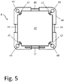
- the container 1 further comprises a bag-holding element 8, which is adapted to be fixed to the frame element 4 when the container 1 is in the collection configuration.
- the bag-holding element 8 comprises a pair of handles 81 arranged transverse to each other and designed to be connected to at least two bags (not shown) to support them.
- the bag-holding element 8 further comprises a perimeter structure 82 connected to the handles 81 and designed to be fastened to the frame element 4 when the container is in the collection configuration.
- the bag-holding element 8 may further comprise a bag strap 83 connected to the handles 81 and configured to close a corresponding bag, e.g. an organic waste bag.
- the bag-holding element 8 when fixed to the frame element 4 of the container 1 in the collection configuration, affords waste differentiation. Therefore, the container 1 of the present patent application can be also used for separate waste collection.
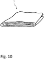
- the container 1 further comprises a band of flexible fabric 9 connected to the base 2 and to the frame element 4 to close the container 1 at its sides in the collection configuration.
- the band of flexible fabric 9 can be fixed to the base 2 and to the frame element 4 by means of Velcro straps 11 arranged along the perimeter edges 20, 40 of the base 2 and of the frame element 4.
- the band of flexible fabric 9, when fixed to the base 2 and to the frame element 4 can hide the contents of the container 1 in the collection configuration.
- the frame element 4 abutting the base 2 defines an inner cavity 11 which is delimited by the frame element at the sides and by the base 2 at the bottom.
- the inner cavity 11 is configured to receive the rods 7 and the band of fabric 9 therein when the container 1 is in the transport configuration.
- the container 1 in the transport configuration contains all the parts required to be converted into the collection configuration.
- the container 1 can be easily assembled from the transport configuration.
- the user can assemble the container and convert it into the collection configuration from the transport configuration.
- the rods 7 are assembled at least in pairs at their respective ends 72, 73 to form the support elements 70, which are then slid onto their respective pins 3.
- the frame element 4 is caused to slide directly through the holes 41 on the support 70 until it reaches the appropriate recesses 71 of the rods 7, where it is locked by the locking means 43.
- the cover 5 is fixed via the at least one hinge 10 to the frame element 4 and the flexible fabric 9 is connected to the base 2 and to the frame element 4 by means of the Velcro straps 11, to close the container 1 at the top and at the sides.
- the bag-holding element 8 is also provided, and attached to the frame element 4 via the perimeter structure 82, by passing the handles 81 through the appropriate channels 45, thereby allowing a plurality of individual bags to be fixed in the slots 84 formed in the handles 81.
Landscapes
- Engineering & Computer Science (AREA)
- Mechanical Engineering (AREA)
- Processing And Handling Of Plastics And Other Materials For Molding In General (AREA)
- Processing Of Solid Wastes (AREA)
- Details Of Rigid Or Semi-Rigid Containers (AREA)
Applications Claiming Priority (1)
| Application Number | Priority Date | Filing Date | Title |
|---|---|---|---|
| IT102020000029867A IT202000029867A1 (it) | 2020-12-04 | 2020-12-04 | Contenitore porta rifiuti |
Publications (1)
| Publication Number | Publication Date |
|---|---|
| EP4008652A1 true EP4008652A1 (de) | 2022-06-08 |
Family
ID=74759303
Family Applications (1)
| Application Number | Title | Priority Date | Filing Date |
|---|---|---|---|
| EP21163805.1A Withdrawn EP4008652A1 (de) | 2020-12-04 | 2021-03-19 | Müllbehälter |
Country Status (2)
| Country | Link |
|---|---|
| EP (1) | EP4008652A1 (de) |
| IT (1) | IT202000029867A1 (de) |
Citations (4)
| Publication number | Priority date | Publication date | Assignee | Title |
|---|---|---|---|---|
| US6446919B1 (en) * | 2001-08-17 | 2002-09-10 | Rouh-Farm Tsui | Size-adjustable detachable portable garbage bag rack |
| DE20221113U1 (de) * | 1970-05-22 | 2005-05-12 | Curver B.V. | Vorrichtung zum Halten eines Sackes und/oder eines Eimers |
| US20130256314A1 (en) * | 2010-12-06 | 2013-10-03 | Pierre MARCONI | Waste collecting device |
| CH712831A2 (de) * | 2016-08-23 | 2018-02-28 | Baechler Alex | Abfallsackhalter mit Komprimierfunktion. |
-
2020
- 2020-12-04 IT IT102020000029867A patent/IT202000029867A1/it unknown
-
2021
- 2021-03-19 EP EP21163805.1A patent/EP4008652A1/de not_active Withdrawn
Patent Citations (4)
| Publication number | Priority date | Publication date | Assignee | Title |
|---|---|---|---|---|
| DE20221113U1 (de) * | 1970-05-22 | 2005-05-12 | Curver B.V. | Vorrichtung zum Halten eines Sackes und/oder eines Eimers |
| US6446919B1 (en) * | 2001-08-17 | 2002-09-10 | Rouh-Farm Tsui | Size-adjustable detachable portable garbage bag rack |
| US20130256314A1 (en) * | 2010-12-06 | 2013-10-03 | Pierre MARCONI | Waste collecting device |
| CH712831A2 (de) * | 2016-08-23 | 2018-02-28 | Baechler Alex | Abfallsackhalter mit Komprimierfunktion. |
Also Published As
| Publication number | Publication date |
|---|---|
| IT202000029867A1 (it) | 2022-06-04 |
Similar Documents
| Publication | Publication Date | Title |
|---|---|---|
| US5862917A (en) | Pallet sleeve clip with visible positive open and closed positions | |
| EP2773236B2 (de) | Gepäck mit einem ratschenartiges erweiterungssystem | |
| US9403623B2 (en) | Adjustable, reusable packing crate | |
| US20120255824A1 (en) | Mobile luggage system | |
| US20140261533A1 (en) | Compact Organizer for Cosmetics | |
| US20140291328A1 (en) | Bag retention system and field configurable waste and recycling receptacles and systems employing same | |
| US20040118854A1 (en) | Cargo storage and organization apparatus | |
| EP2644534A1 (de) | Behälter für Walzenkörper | |
| JP2017218227A (ja) | 輸送容器 | |
| US2777597A (en) | Stackable tote box construction | |
| EP4008652A1 (de) | Müllbehälter | |
| EP4255249B1 (de) | Kompressionsexpansionsverriegelungsvorrichtung für gepäck und gepäck damit | |
| EP2868592B1 (de) | Behälter mit einem Deckel und Mittel zur Sicherung des Deckels an der Basis des Behälters | |
| US7784632B2 (en) | Collapsible cargo organizer | |
| US11813731B2 (en) | Carrier having a rigid container and sleeve organizer | |
| US3034617A (en) | Handle member for luggage and other portable containers | |
| US9938053B2 (en) | Container having a closable loading opening | |
| KR200449263Y1 (ko) | 컨테이너 | |
| JPH10218173A (ja) | 展開可能な組立容器 | |
| KR101480666B1 (ko) | 결합 구조를 구비하는 조립식 유닛 박스용 슬리브 및 이를 구비하는 조립식 유닛 박스 | |
| EP2250922B1 (de) | Kombinierte Transport- und Ausstellungsvorrichtung | |
| RU2852821C1 (ru) | Укладка врача скорой медицинской помощи | |
| GB2179027A (en) | Boxes for storing and carrying document files | |
| US20230366419A1 (en) | Cam for a base for transport | |
| KR200279589Y1 (ko) | 다양한 높이의 물건이 수납될 수 있는 휴대용 케이스 |
Legal Events
| Date | Code | Title | Description |
|---|---|---|---|
| PUAI | Public reference made under article 153(3) epc to a published international application that has entered the european phase |
Free format text: ORIGINAL CODE: 0009012 |
|
| STAA | Information on the status of an ep patent application or granted ep patent |
Free format text: STATUS: THE APPLICATION HAS BEEN PUBLISHED |
|
| AK | Designated contracting states |
Kind code of ref document: A1 Designated state(s): AL AT BE BG CH CY CZ DE DK EE ES FI FR GB GR HR HU IE IS IT LI LT LU LV MC MK MT NL NO PL PT RO RS SE SI SK SM TR |
|
| STAA | Information on the status of an ep patent application or granted ep patent |
Free format text: STATUS: THE APPLICATION IS DEEMED TO BE WITHDRAWN |
|
| 18D | Application deemed to be withdrawn |
Effective date: 20221209 |